policy on distribution of component drawings · the purpose of this marine application bulletin is...
TRANSCRIPT
Subject:
Alternator Conversions
This AEB is for the following applications:
Automotive Industrial G-Drive Marine
Date Created: 2/08/2007 Revision Date: 2/08/2007 Expire Date: 3/26/2008
File Name : 0.13.01
Alternators & Charging
System
MAB No. 0.13.01-12/08/2006
Engine Family : Midrange, Heavy Duty
Engine Model : QSB, QSC, QSL, QSM
Document Owner : Aimee Nagy Page 1 of 12
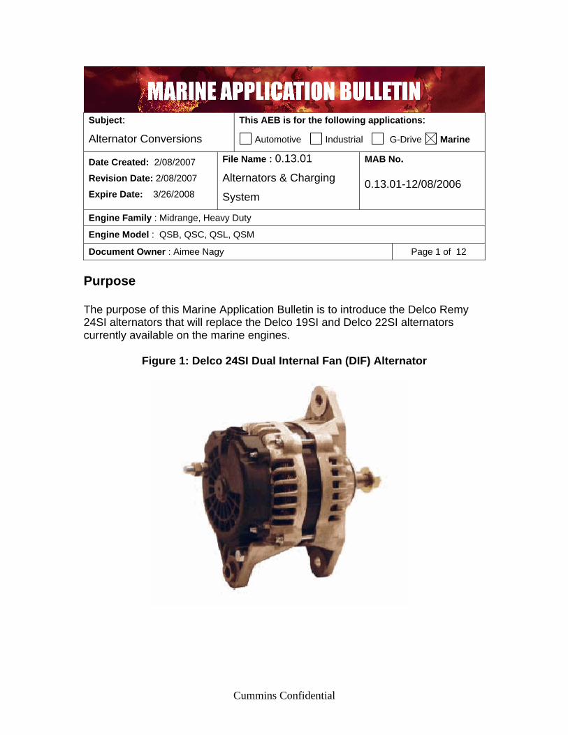
Purpose The purpose of this Marine Application Bulletin is to introduce the Delco Remy 24SI alternators that will replace the Delco 19SI and Delco 22SI alternators currently available on the marine engines.
Figure 1: Delco 24SI Dual Internal Fan (DIF) Alternator
Cummins Confidential
Introduction Delco Remy is discontinuing production of the 19SI in April of 2007. As of February 15th, 2007, Delco Remy will no longer accept orders for the 19SI alternator. As a suitable replacement for the 12V 105A 19SI, Cummins will offer the 12V 160A Delco Remy 24SI 3-wire alternator. The 22SI alternator is set to be obsolete in Cummins systems in the 3rd quarter of 2007. The 24SI alternator has been released as a replacement for all current rated 22SI alternators. Discussion The 24SI alternator is a direct replacement for the 19SI and 22SI. It offers several operational advantages, the primary advantage is the DIF (Dual internal Fan) feature, which will help remove heat from the alternator and add to component life. The 24SI alternator is approximately the same physical size as both the 19SI and 22SI alternators. Since the external cooling fan is no longer present on the front face of the alternators, the outside diameter of the front of the alternator is smaller, and therefore should not present any clearance issues with belt guards. In addition, the rear electrical connections to the alternator now are covered by a cover plate assembly providing added protection from the external environment. Cummins Marine and Cummins Mercury Diesel are offering the 24SI alternator with or without a sensing terminal. The 24SI with a sensing terminal will be classified as the three-wire alternator. The 24SI without the sensing terminal will be classified as the one-wire alternator. The 24SI alternator is NOT an isolated alternator. The mounting option and customer electrical connection are different on the 19SI when compared to the 24SI. Table 1 shows a conversion matrix for the 19SI EE and EH options compared to the 24SI EE and EH options.
Table 1: 19SI to 24SI Conversion Matrix (EE and EH options)
Engine Family 19SI Alt 19SI Mtg 24SI Alt 24SI Mtg 4B EE 9113 EH 9329 EE 9318 TBD 6B EE 9113 EH 9329 EE 9318 EH 97653 QSB EE 9229 EH 9616 EE 9335 EH 9643
* A customer specifying 19SI (EE 9229 and EH 9616) should now specify 24SI (EE 9335 and EH 9643)
Page 2 of 12

The mounting option (EH option) for the 22SI are identical for the 24SI. Table 2 shows an option matrix for the 22SI EE options compared to the 24SI EE options.
Table 2: 22SI to 24SI Conversion Matrix (EE options)
Old Alternator
Option
Old Alternator Part Num.
New Alternator
Option
New Alternator Part Num.
Alternator Description
( New Option ) EE9288 EE 2049
3935529 EE9246 EE 2071
4936878 Delco 24 SI 12 VDC@160 Amp
1 wire EE2050 3935530 EE2072 4936879 Delco 24 SI
24 VDC@70 Amp 1 wire
EE2053 EE 9118 EE 9177
4003445 EE2081 EE 9318 EE 9335
4938604 Delco 24 SI 12 VDC@160 Amp
3 wire EE2054 EE 9119 EE 9178
4003446 EE2082 EE 9319 EE 9336
4938607 Delco 24 SI 24 VDC@70 Amp
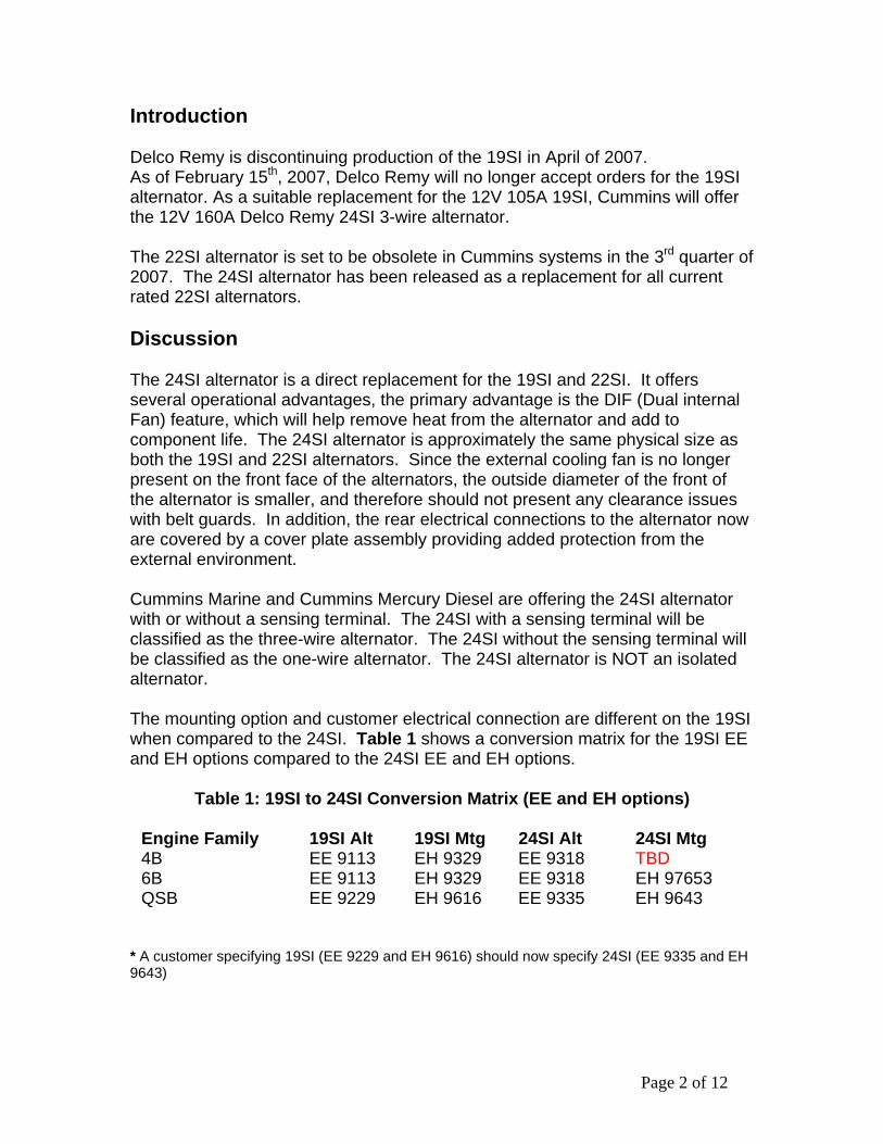
3 wire The graphics below show the envelope for the 19SI and its mounting (shaded) vs. the envelope for the 24SI and its mounting. Figure 2 shows the envelope comparison for the 2-Valve 4B/6B in both the front view and left side view. Figure 3 shows the envelope comparison for 4-Valve QSB in both the front view and the left side view.
Figure 2: Envelope Comparison 4B/6B
Page 3 of 12
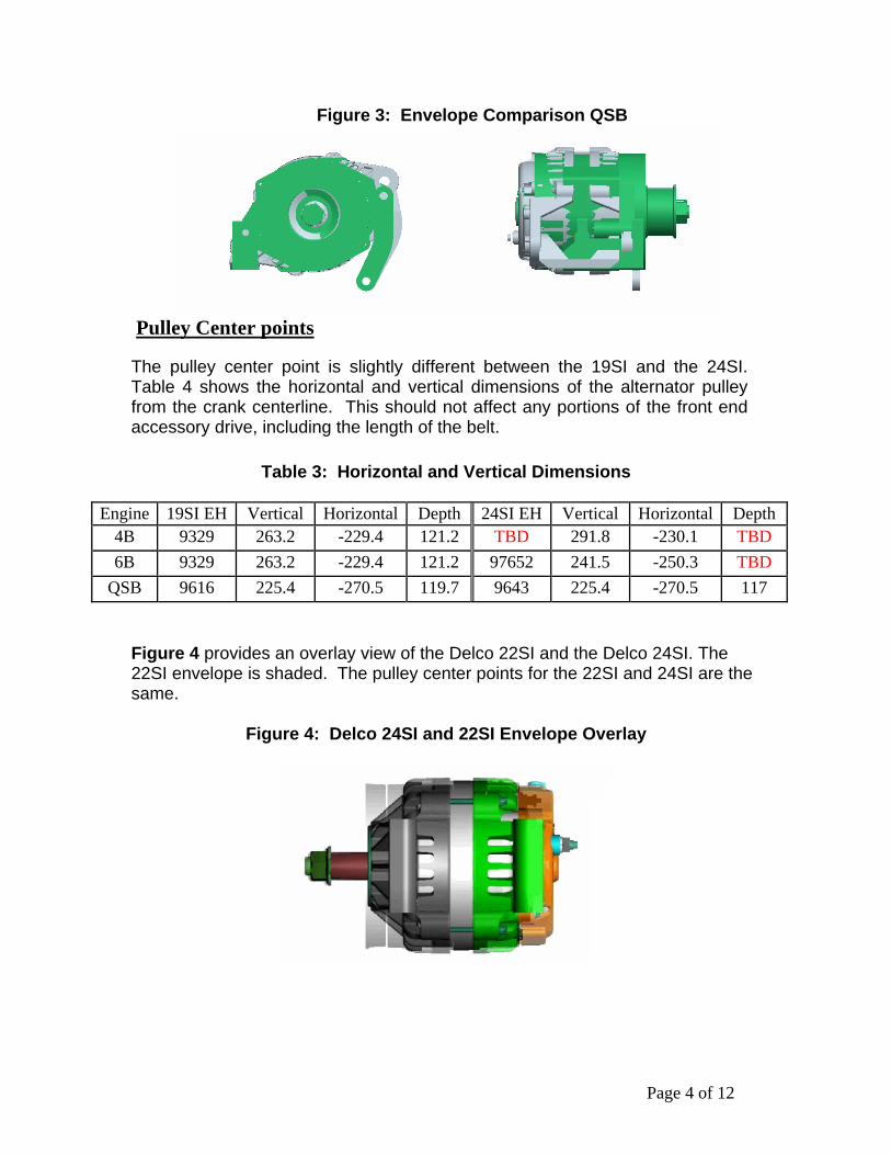
Figure 3: Envelope Comparison QSB
Pulley Center points
The pulley center point is slightly different between the 19SI and the 24SI. Table 4 shows the horizontal and vertical dimensions of the alternator pulley from the crank centerline. This should not affect any portions of the front end accessory drive, including the length of the belt.
Table 3: Horizontal and Vertical Dimensions
Engine 19SI EH Vertical Horizontal Depth 24SI EH Vertical Horizontal Depth 4B 9329 263.2 -229.4 121.2 TBD 291.8 -230.1 TBD 6B 9329 263.2 -229.4 121.2 97652 241.5 -250.3 TBD
QSB 9616 225.4 -270.5 119.7 9643 225.4 -270.5 117
Figure 4 provides an overlay view of the Delco 22SI and the Delco 24SI. The 22SI envelope is shaded. The pulley center points for the 22SI and 24SI are the same.
Figure 4: Delco 24SI and 22SI Envelope Overlay
Page 4 of 12
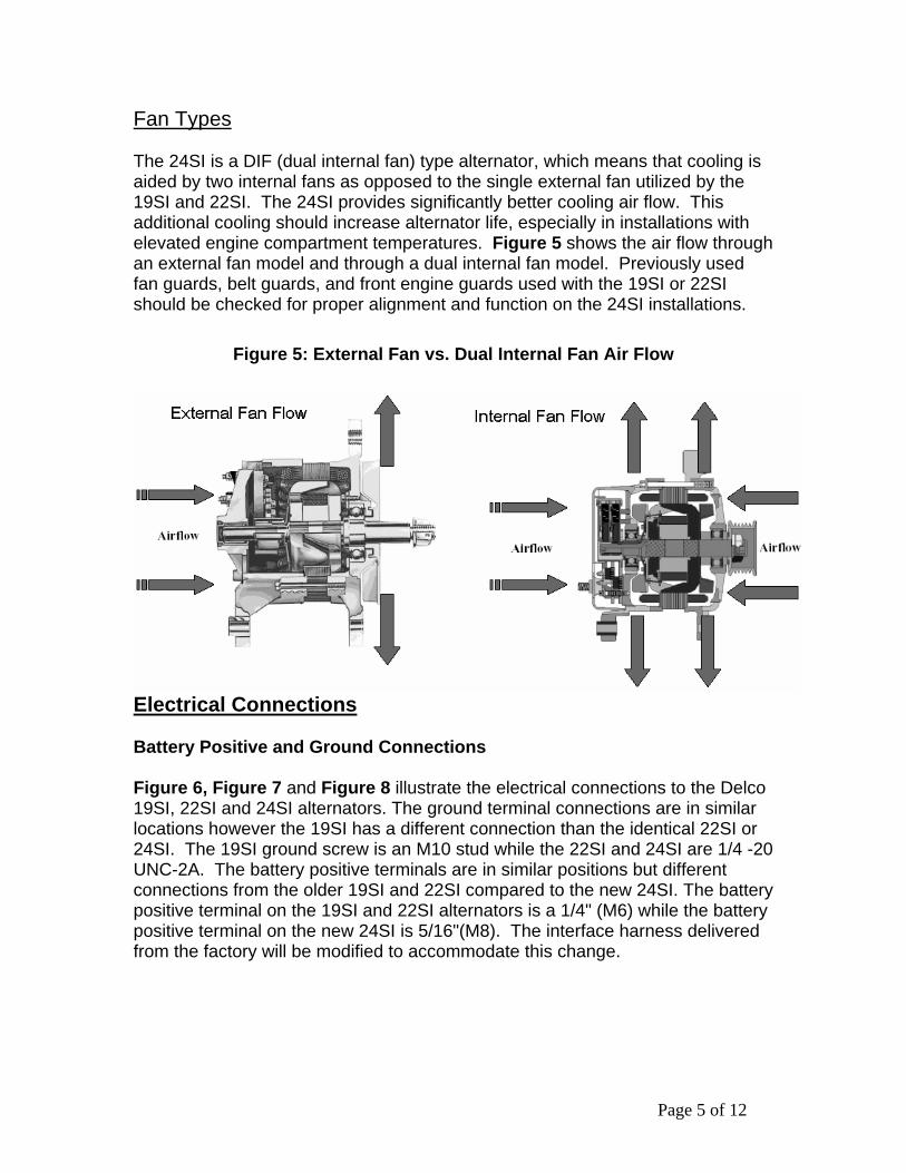
Fan Types The 24SI is a DIF (dual internal fan) type alternator, which means that cooling is aided by two internal fans as opposed to the single external fan utilized by the 19SI and 22SI. The 24SI provides significantly better cooling air flow. This additional cooling should increase alternator life, especially in installations with elevated engine compartment temperatures. Figure 5 shows the air flow through an external fan model and through a dual internal fan model. Previously used fan guards, belt guards, and front engine guards used with the 19SI or 22SI should be checked for proper alignment and function on the 24SI installations.
Figure 5: External Fan vs. Dual Internal Fan Air Flow
Electrical Connections Battery Positive and Ground Connections Figure 6, Figure 7 and Figure 8 illustrate the electrical connections to the Delco 19SI, 22SI and 24SI alternators. The ground terminal connections are in similar locations however the 19SI has a different connection than the identical 22SI or 24SI. The 19SI ground screw is an M10 stud while the 22SI and 24SI are 1/4 -20 UNC-2A. The battery positive terminals are in similar positions but different connections from the older 19SI and 22SI compared to the new 24SI. The battery positive terminal on the 19SI and 22SI alternators is a 1/4" (M6) while the battery positive terminal on the new 24SI is 5/16"(M8). The interface harness delivered from the factory will be modified to accommodate this change.
Page 5 of 12
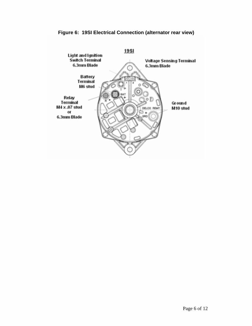
Figure 6: 19SI Electrical Connection (alternator rear view)
Page 6 of 12

Figure 7: 22SI Electrical Connection (alternator rear view)
Figure 8: 24SI Electrical Connections (alternator rear view)
Sense
Page 7 of 12
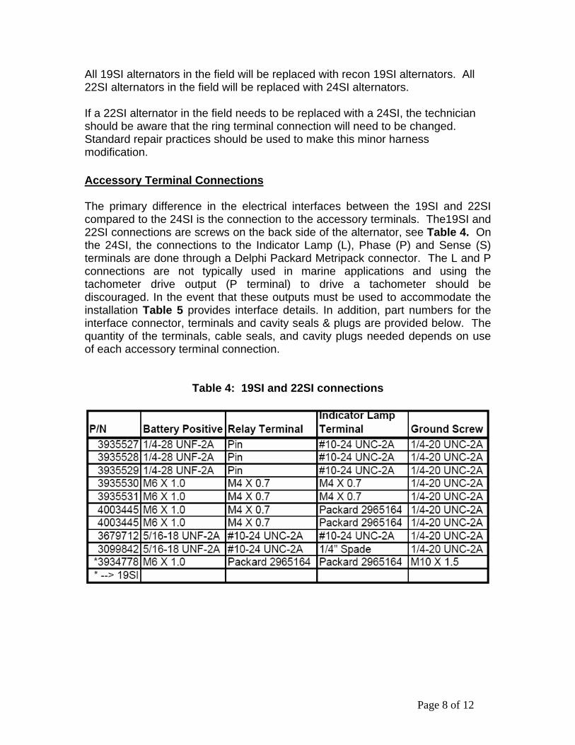
All 19SI alternators in the field will be replaced with recon 19SI alternators. All 22SI alternators in the field will be replaced with 24SI alternators. If a 22SI alternator in the field needs to be replaced with a 24SI, the technician should be aware that the ring terminal connection will need to be changed. Standard repair practices should be used to make this minor harness modification.
Accessory Terminal Connections The primary difference in the electrical interfaces between the 19SI and 22SI compared to the 24SI is the connection to the accessory terminals. The19SI and 22SI connections are screws on the back side of the alternator, see Table 4. On the 24SI, the connections to the Indicator Lamp (L), Phase (P) and Sense (S) terminals are done through a Delphi Packard Metripack connector. The L and P connections are not typically used in marine applications and using the tachometer drive output (P terminal) to drive a tachometer should be discouraged. In the event that these outputs must be used to accommodate the installation Table 5 provides interface details. In addition, part numbers for the interface connector, terminals and cavity seals & plugs are provided below. The quantity of the terminals, cable seals, and cavity plugs needed depends on use of each accessory terminal connection.
Table 4: 19SI and 22SI connections
Page 8 of 12

Table 5: Alternator L and P Interface Details
Tachometer Output Indicator Light/Field Excitation - Ignition Terminal
Field Monitor
Name Connector
Connector Info Info
Freq: Alt RPM/10
Diode (5 Amp)
4 Amp Max. Draw
10 ohm resistor recommended
Delco 19SI
Relay Terminal ® or Blade
M4 X .07 Stud / 6.3mm Blade
Voltage: ½ Syst. V
L & I (lamp and excitation)
6.3mm Blade
3 CP Bulb
N/A
Freq: Alt RPM/10 4 Amp Max. Draw
Delco 22SI
Relay (R) See Figure 7 – 22SI Electrical Connection Voltage: ½
Syst. V
Indicator Lamp (L), Excitation
See Figure 7 – 22SI Electrical Connection
1 Amp Max Draw Voltage: System V 3 Cp Bulb
Freq: Alt RPM/10 4 Amp Max. Draw
Delco 24SI
Phase (P)
Combined Metripack
Voltage: ½ Syst. V
Indicator Lamp (L), Excitation
Combined Metripack
"L" terminal not designed to source current.
(Function) Rotor Field Current Duty Cycle
Page 9 of 12
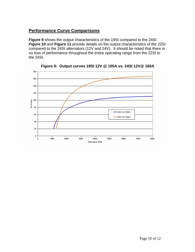
Performance Curve Comparisons Figure 9 shows the output characteristics of the 19SI compared to the 24SI. Figure 10 and Figure 11 provide details on the output characteristics of the 22SI compared to the 24SI alternators (12V and 24V). It should be noted that there is no loss of performance throughout the entire operating range from the 22SI to the 24SI.
Figure 9: Output curves 19SI 12V @ 105A vs. 24SI 12V@ 160A
Page 10 of 12

Figure 10: Output curves 24SI 12V @ 160A vs. 22SI 12V @ 160A 2 4 S I/2 2 S I 1 2 V 1 6 0 A m p C o m p a ris o n
0
20
40
60
80
100
120
140
160
180
0 1000 2000 3000 4000 5000 6000 7000 8000 9000
R P M
Am
p
24S I 12V/160 A 22S I 12V 160A
Figure 11: Output curves 24SI 24V @ 70A vs. 22SI 24V @ 70A 2 4 S I/2 2 S I 2 4 V 7 0 A C o m p a ris o n
0
10
20
30
40
50
60
70
80
90
0 1000 2000 3000 4 000 5 0 00 6 00 0 70 00 800 0 9000
R P M
Am
p
24S I 2 4V/70 A 2 2S I 24V 70 A
Summary of Alternator Changes The Delco 24SI alternators offer several operational benefits over the 22SI products. Those benefits are detailed below.
Page 11 of 12

• 24SI has smaller slip rings significantly reducing ring wear. • 24SI provides a higher (+12C) operating temp. Max. inlet temperature now
+105C. • 24SI has larger bearings for increased bearing life. • 24SI has a convection and conduction cooled rectifier. • 24SI is quieter (approximately 8 dBa) operation at all operating speed. Change Log
Date Change Page Revising Author’s Name
1/29/2007 New MAB Aimee Nagy 3/26/2007 Published to the Web DDC
Distribution of this document is intended for Cummins personnel and distributors. The information contained in this document is only considered valid while published on the Marine Website. Copies and archived documents are not considered current.
Page 12 of 12