polish-american engineers association presenter … · · 2012-07-20geofoam usage – 1999 to...
TRANSCRIPT

Polish-American Engineers Association
Presenter
Jim Nugent – ACH Foam Technologies
Architectural Sales
708-363-2164
www.achfoam.com

ArchitecturalBlocksCut StockEIFSGarage DoorGeofoamICF PlankLaminatedRoofingSIPsRadiant Floor PanelsUltraScreenShape Molding
IndustrialBlocksNon-EPS FoamEPS BeadsICF ContractLoose FillOEMPackagingInsulated ContainersRVToolingShape MoldingLost Foam
Product LineLearning Unit Topics

Geofoam
Basics & Applicaions
Geofoam
Basics & Applicaions
AIA Continuing Education Provider #K155

AIA CES Program
ACH Foam Technologies is a Registered Provider with The American Institute of Architects Continuing Education Systems. Credit earned on completion of this program will be reported to CES Records for AIA members.
Certificates for non-AIA members are available upon request.
This program is registered with the AIA / CES for continuing professional education. As such, it does not include content that may be deemed or construed to be an approval or endorsement by AIA of any material of construction or any method or manner of handling, using, distributing or dealing in any material or product.
Questions related to specific materials, methods, and services will be addressed at the conclusion of this presentation.

Objectives
Review the History of Geofoam
Understand the properties of Geofoam & How it Solves Engineering and Geotechnical Problems
Become familiar with Geofoam Applications & Physical Properties
Review Design and Installation Considerations

History of GeofoamHistory of Geofoam

Flom Bridge 1972 Norway

The Problem

The Problem

The Problem

The Solution
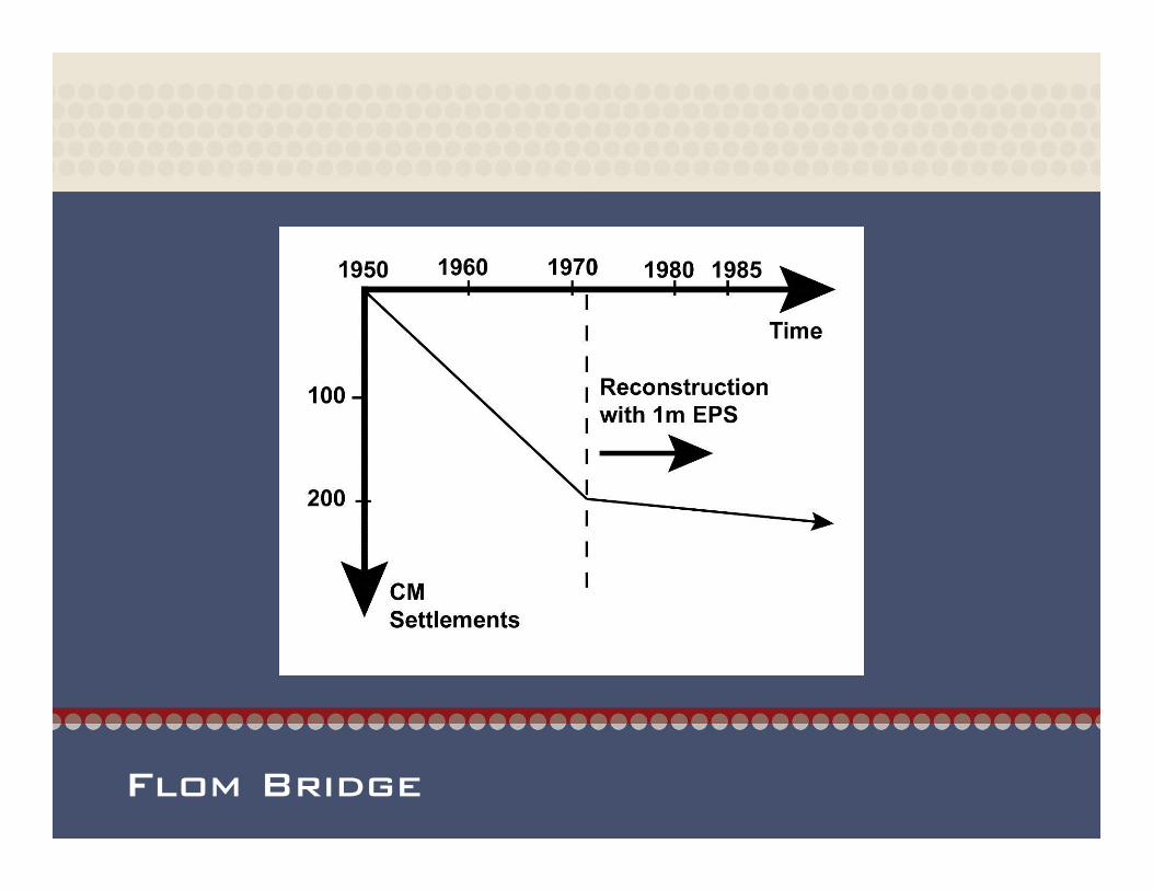
Flom Bridge

Flom Bridge

Constructed in 1990
Unstable soil conditions made the project not suitable for normal construction
Unstable soils were removed
28,000 CU Meters of GeoFoam were placed below the foundation
Zero net load
Carousell Mall Syracuse, NY

Geofoam Usage – 1999 to 2005
US Estimated Market Size
• Between 35-45 Million Lbs of EPS
• About 900,000 y³ of Geofoam
• About 8% of total EPS construction sales
• 28% CAGR since 1999 without I-15
• 24% CAGR with I-15
0100,000200,000300,000400,000500,000600,000700,000800,000900,000
1,000,000
1999 w/1-15
1999 2000 2001 2002 2003 2004 2005
Cub
ic Y
ards
of G
eofo
am
Commercial/OtherHighway/Transportation
05,000,000
10,000,00015,000,00020,000,00025,000,00030,000,00035,000,00040,000,000
1999 w/1-15
1999 2000 2001 2002 2003 2004 2005
LBS
of E
PS
2005 BreakdownHighway 43%Commercial 57%
2005 BreakdownHighway 47%Commercial 53%

Problem SolverProblem Solver

What is EPS Geofoam?
•A geotechnical product used in fill applications where a lightweight material is required to reduce stress on underlying soils or lateral pressures to retaining walls, abutments or foundations.
•Is a cellular plastic material that is strong, but has a very low density – 1 percent of traditional earth materials.
•Geofoam has been used in engineering and geotechnical applications worldwide for more than 30 years.

Why is Geofoam a Problem Solver?
Weight Comparisons
Regular Fill 120-130 LB/F3
Sand 106 LB/F3
Saw Dust 60 LB/F3
EPS 39 2.40 LB/F3*
EPS 19 1.15 LB/F3**other engineered densities available

Manufacturing Process

What is EPS?

Benefits of Geofoam
High Strength
Predictable Performance No Settlement
Densities Engineered for Applications
Low Water Absorption
Economical
Easily Modified on Jobsite
Variety of Sizes & Shapes
Termite Resistance
Environmentally Friendly

Problem: Unusable Above-Grade Space
Below-Grade Parking Structure
near Downtown Chicago
created unusable above grade
space for buildings, parks and
city amenities.
City planners wanted to build a
cutting-edge facility for cultural
events and free public use.

Solution: Geofoam for Green Roof
Geofoam was specified to
reduce the load on the
below-grade parking
structure.
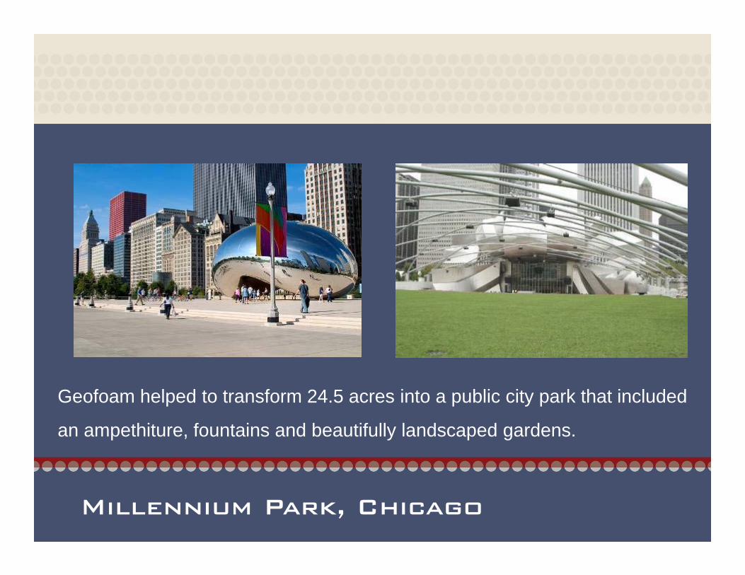
Millennium Park, Chicago
Geofoam helped to transform 24.5 acres into a public city park that included
an ampethiture, fountains and beautifully landscaped gardens.

Problem: Floor Elevation Changes
Fort Hayes Student Union was in
need of updating. Prior to renovation
the student union was used for
entertaining and office spaces. As the
university grew so did the need for
more office space, as well as an area
for formal gatherings.
Fort Hays, KS

Solution: Geofoam for Easy Installation & Handling
Geofoam was specified rather than compacted fill for its speed of installation, ease
of handling and ability to be easily modified to meet design requirements.

Fort Hays University Student Union
Geofoam created floor elevation changes for stairs, ramps and stages without making costly changes to the building’s structure.

Problem: Reduce Lateral Pressure
A light weight fill was needed to reduce lateral pressure on a footing wall which extended 25 feet below grade.
Intermountain Medical Center – Murray, UTWidth of foundation reduced from 30” to 18”

Solution: Geofoam Foundation Stabilization Fill
The reduction of earth pressure allowed a much thinner wall to be built, saving tens of thousands of dollars and considerable time.

Geofoam ApplicationsGeofoam Applications

Embankment and Slope Stabilization
Left - I-15 Expansion Right - Window Rock Highway, UTSalt Lake City, UT

I-15 Project: Problem
Reduce Settlement to Protect Buried Utilities
Improve Slope Stability of Embankments
Rapid Construction in Time Critical Areas
I-15 Expansion Salt Lake City, UTPart of the preparations for the 2002 Winter Olympics
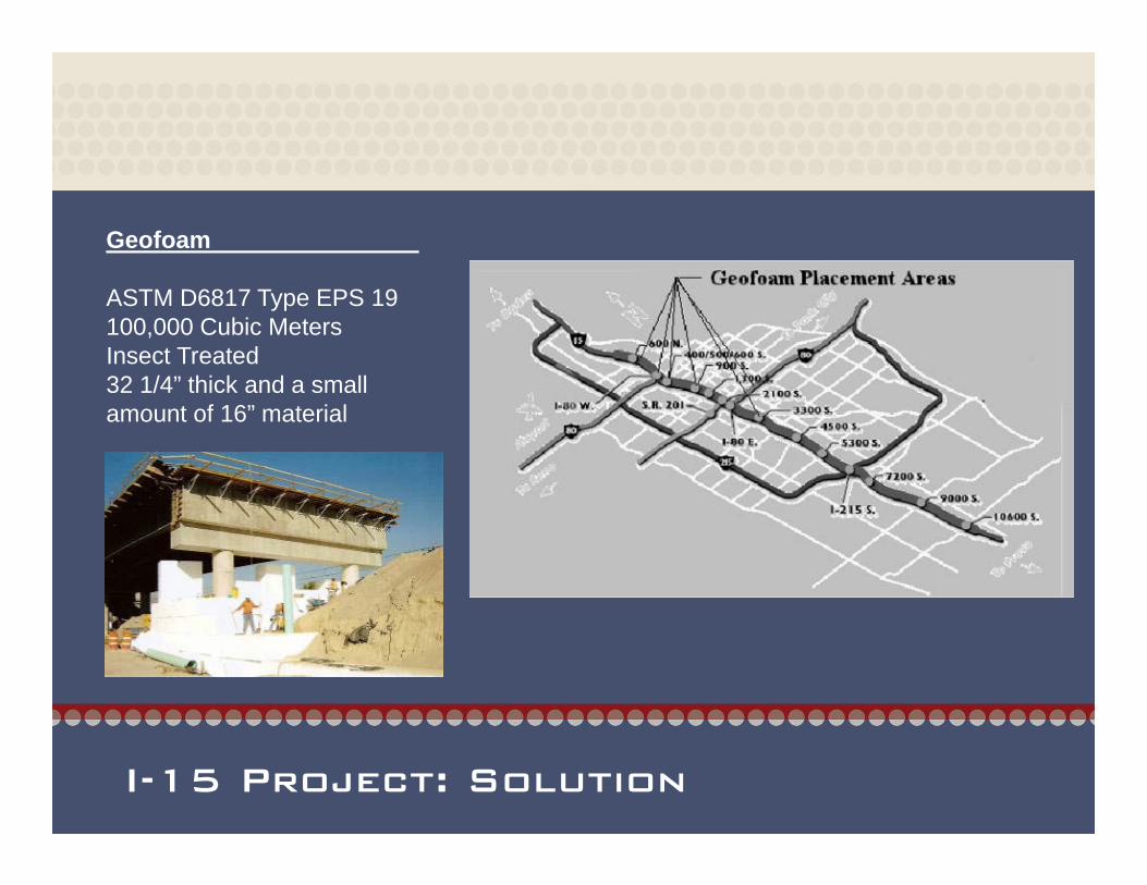
I-15 Project: Solution
Geofoam
ASTM D6817 Type EPS 19 100,000 Cubic MetersInsect Treated32 1/4” thick and a small amount of 16” material

I-15 Project: Arial View
Settlement Reduction, Utility Protection, Speed of Construction
Geofoam Embankment from State St. to 200 W. Along Interstate I-80, Salt Lake City, Utah

Green Roofs & Landscapes
California Academy of Sciences – San Francisco, CALoad Reduction over Parking Garage

Green Roofs & Landscapes
Fidelity Towers Kansas City, MOAsphalt Roof Converted in to Usable Outdoor Space

Green Roofs & Landscapes
LDS Conference CenterSalt Lake City, UTProject reduced the use of potting soil and concrete22,000,0000 pounds of weight reduction

Green roof & Landscape Installation
Soldier Field, Chicago, IL

Floor Elevation
Union Pacific Depot RestorationSalt Lake City, UT

Floor Elevation

Stadium Seating

Stadium Seating

Retaining Structures
Judge Memorial High School30-40’ retaining walls at far end of the field

Slope Stabilization
Plumas Forest – Oroville CAGeoFoam allowed for installation of culverts for run off

Hillside Foundation Stabilization

Foundation Stabilization
Parkwood Place Park City, UTReduced foundation pressure

Erosion Control
Hanging Lake, COCompressible InclusionProtected tunnel from falling debris

Culvert Protection
Left Quartzite, AZ Right Alton IA

Utility Protection
I-15 Expansion Salt Lake City, UT72’ fiber optic cable protected$3,000,000 savings

Concrete Void

Application Summary
Bridge Abutment
Lightweight Void Fill
Structural Fill
Bridge Approach Fill
Retaining Walls
Side Hill Stabilization
Vibration & Sound Dampening
Levees & Berms

Design ConsiderationsDesign Considerations

Geo Foam Standard ASTM D6817
Geofoam PropertiesTYPE-ASTM D6817 EPS 12 EPS 15 EPS 19 EPS 22 EPS 29 EPS 39 EPS46
Density, min. lb/ft³(kg/m³)
0.70 (11.2)
0.90 (14.4)
1.15 (18.4)
1.35 (21.6)
1.80 (28.8)
2.40 (38.4)
2.85(45.7)
Compressive Resistance @ 1% deformation, min.
psipsf
(kPa)
2.2320(15)
3.6520(25)
5.8840(40)
7.31050(50)
10.91570(75)
15.02160(103)
18.62680(128)
Elastic Modulus, min psi(kPa)
220(1500)
360(2500)
580(4000)
730(5000)
1090(7500)
1500(10300)
1860(12800)
Flexural Strength, min. psi(kPa)
10.0(69)
25.0(172)
30.0(207)
40.0(276)
50.0(345)
60.0(414)
75.0(517)
Water Absorption by total immersion, max.
Volume % 4.0 4.0 3.0 3.0 2.0 2.0 2.0
Oxygen Index, min. Volume % 24.0 24.0 24.0 24.0 24.0 24.0 24.0
Buoyancy Force lb/ft³(kg/m³)
61.7(990)
61.5(980)
61.3(980)
61.1(980)
60.6(970)
60.0(960)
59.5(950)
Additional Properties for Compressible Applications
Compressive Resistance @ 5% deformation, min.
psipsf
(kPa)
5.1730(35)
8.01150(55)
13.11890(90)
16.72400(115)
24.73560(170)
35.05040(241)
43.56260(300)
Compressive Resistance @ 10% deformation, min
psipsf
(kPa)
5.8840(40)
10.21470(70)
16.02300(110)
19.62820(135)
29.04180(200)
40.05760(276)
50.07200(345)

Insulation Standard ASTM C578
EPS Properties
Property Type XI
Type I
Type VIII
TypeII
TypeIX
Type XIV
Type XV
Nominal Density lb/ft³(kg/m³)
0.75(12)
1.00(16)
1.25(20)
1.50(24)
2.00(32)
2.50(40)
3.00(48)
Density¹, min. lb/ft³(kg/m³)
0.70(12)
0.90(15)
1.15(18)
1.35(22)
1.80(29)
2.40(38)
2.85(46)
Design Thermal Resistance per 1.0 in. thickness
75°F °F·ft²·h/Btu(°K·m²/W)
3.22(0.57)
3.85(0.68)
3.92(0.69)
4.17 (0.73)
4.35 (0.77)
4.35 (0.77)
5.10(0.90)
40°F °F·ft²·h/Btu(°K·m²/W)
3.43 (0.60)
4.17 (0.73)
4.25 (0.75)
4.55 (0.80)
4.76 (0.84)
4.76 (0.84)
4.85(0.85)
Compressive Strength¹@ 10% deformation, min.
psi(kPa)
5.0 (35)
10.0 (69)
13.0(90)
15.0 (104)
25.0 (173)
40.0 (256)
60.0(414)
Flexural Strength¹, min. psi(kPa)
10.0 (69)
25.0 (173)
30.0 (208)
35.0 (242)
50.0 (345)
60.0 (414)
75.0(517)
Water Vapor Permeance¹of 1.0 in. thickness, max., perm 5.0 5.0 3.5 3.5 2.5 2.5 2.5
Water Absorption¹by total immersion, max., volume % 4.0 4.0 3.0 3.0 2.0 2.0 2.0

Allowable Stress & Creep
Results of Typical Unconfined Axail Compression Creep Tests on Block-Molded EPS

Allowable Stress & Creep
Stress Allowed to Achieve Maximum 1% Strain
Type Density Stress (PSI) Stress (PSF)
EPS 15 0.90 lb/f³ 3.6 520
EPS 19 1.15 lb/f³ 5.8 840EPS 22 1.35 lb/f³ 7.3 1050
EPS 29 1.80 lb/f³ 10.9 1570EPS 39 2.40 lb/f³ 15.0 2160EPS 46 2.85 lb/f³ 18.6 2680

Bouyancy
Fuplift
Fresisting
groundwater
100-yeardesign floodevent
Drainage Sand
Fresisting = 1.3 x Fuplift
Rule of Thumb; in buoyancy situations 1ft of foam below water = 2ft of cover

Chemical Attack- Protective Barrier
GeomembranePetroleum Resistant(3 component)for exposed side slopeonly
Load Distribution Slab(15 cm - Reinforced)
Concrete Pavement (35 cm)
Tilt-up Panel Wall

Differential Icing – Cold Regions Only
Good Heat Transfer
soil
pavement
60 mm base (min.)
No IcingBase material has heat capacityand prevents pavement from icingas rapidly.
EPS
Poor Heat Transfer
Proper Design to Prevent IcingProper Design to Prevent Icing

Vertical Force Reduction

Horizontal Force Reduction
With Geofoam no horizontal forces act on the bridge abutment and supporting walls

Gripper Plates

Flammability
Geofoam is Combustible and Must Be Protected AgainstOpen Flame or Heat
Material Specification should include:
“Flame Retardant Additive and a UL Certification of Classification as to External Fire Exposure andSurface Burning Characteristics.”

Termite Resistant Geofoam
Geofoam can be manufactured with a proven and safe additive that effectively resists termites
Untreated EPSExtruded Polystyrene Termite Resistant Treated EPS Geofoam

Geofoam InstallationGeofoam Installation

Installation Planning

Leveling Course
Bedding Sand (20 cm min.)
Bedding Sand Function
• free draining sand or fine gravel• provides leveling course • provides drainage

Delivery to Site

Delivery to Site
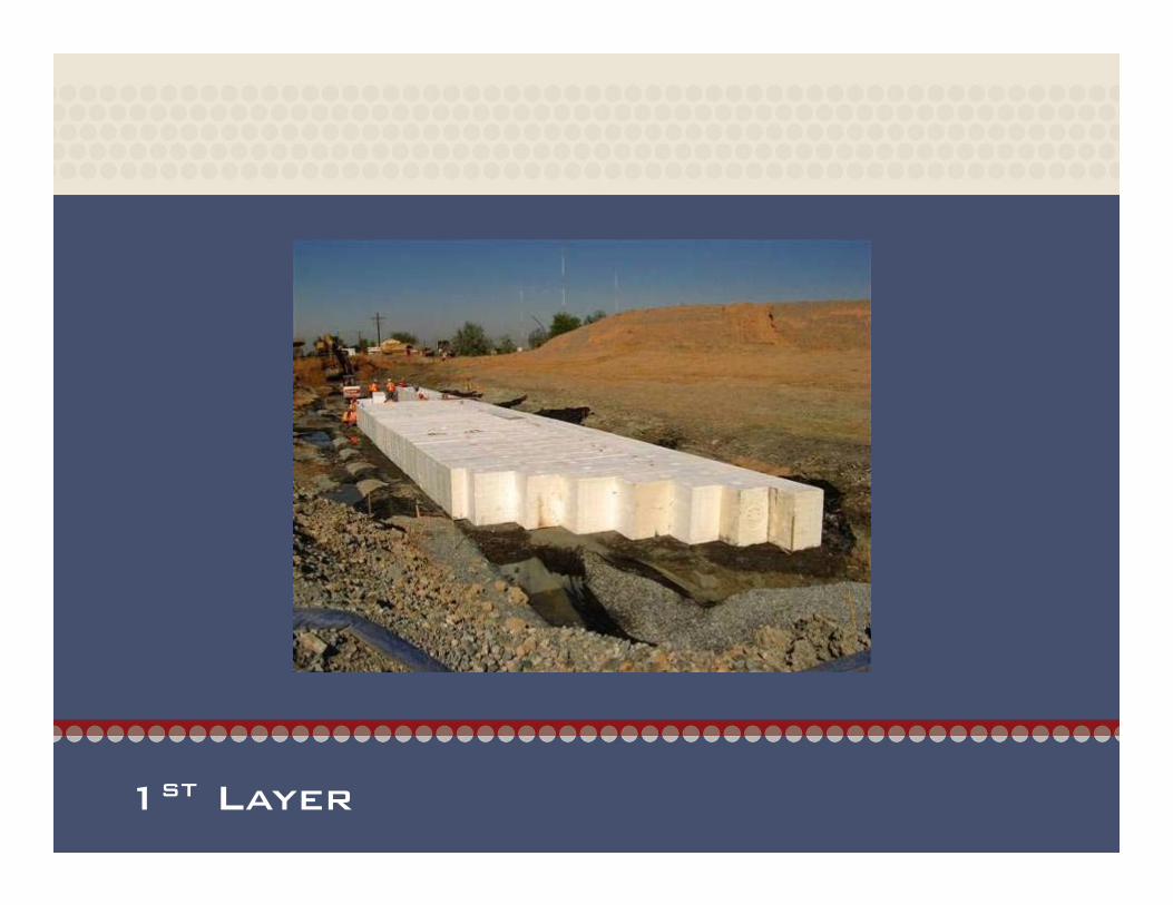
1st Layer
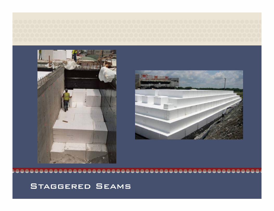
Staggered Seams

Install to Create Ramp or Curved Wall

Easy to Handle

Easy to Modify on Jobsite

Compaction & Placement at Downdrains

Gripper Plate Placement

Load Distribution Slab

Foundation Wall Installation

Questions?Questions?
This Concludes the AIA Continuing Education Program


