polished surface was subsequently etched with
TRANSCRIPT

A
sebirvr©
K
1
sftwbmhmtptt
aem
0d
Materials Science and Engineering A 479 (2008) 45–57
Macro- and micro-surface engineering to improve hot rollbonding of aluminum plate and sheet
Jiantao Liu, Ming Li ∗, Simon Sheu, M.E. Karabin, R.W. SchultzAlcoa Technical Center, 100 Technical Drive, Alcoa Center, PA 15069-0001, United States
Received 11 April 2007; received in revised form 8 June 2007; accepted 11 June 2007
bstract
Hot roll bonding of aluminum plate and sheet currently is the primary manufacturing method of fuselage skin sheet for aircraft and brazingheet for automotive applications. Tremendous challenges and opportunities exist to improve quality and productivity of these products. This workxplored the effects of macro- and micro-surface engineering on hot roll bonding process. It was found that micro-surface engineering yielded betteronding quality than macro-surface engineering did. The critical surface roughness of the core was about 0.58 �m below which bonding qualityn terms of area contact and bonding energy can be significantly improved. However, no marked improvement was observed when the surface
oughness was reduced further to 0.03 �m. Also, the oxide layer on the surface of the core and local deformation on the surface of liner played aery important role. Ultrasonic test and roller peel test were employed to assess the bonding strength and quality. The quantitative ultrasonic testesults are in good agreement with the roller peel test results. 2007 Elsevier B.V. All rights reserved.pspputnpt
ttr[Ico
eywords: Aluminum alloy; Hot roll bonding; Surface engineering
. Introduction
Multi-layered aluminum alloys provide great advantage thaningle alloy for a variety of applications. For example, theuselage skin sheets for commercial airplanes are layered withhe inside structural layer being high strength aluminum alloyhile the outside layer being pure aluminum which is softut has high corrosion resistance. Brazing sheets for auto-otive heat-exchangers are also layered. The outside layer
as lower melting point while the inside layer has higherelting point. The heat-exchangers are press-formed at room
emperature and then put into a furnace. The furnace tem-erature is raised just enough so that the outside layer startso melt and consequently the heat exchanger parts are brazedogether.
The manufacturing process of these multi-layered aluminumlloy sheets or plate is termed Alclad process. The most
conomical and therefore primary method for large-scaleanufacturing is hot roll bonding. Generally, the center layer is∗ Corresponding author. Tel.: +1 724 337 2492; fax: +1 724 337 2135.E-mail address: [email protected] (M. Li).
ho
edsb
921-5093/$ – see front matter © 2007 Elsevier B.V. All rights reserved.oi:10.1016/j.msea.2007.06.022
repared from cast ingot. The top and bottom surfaces arecalped (machined) and then chemically cleaned. The pre-ared ingot is termed “core”. The outside layers are rolledlates, termed “liner”. The liner-core-liner assembly is heatedp in a furnace and then hot rolled by multi-passes to bondhe liner and the core together. The bonding pass (or passes)ormally has very light reduction. After the bonding is com-leted, heavy reductions are used for productivity considera-ion.
Research on the hot roll bonding process is very limited. Inhe open literature studies have been carried out to understandhe effects of surface cleaning [1], rolling conditions such asolling pressure [2,3], temperature [3], reduction [3–5], speed3,4], and friction at the interface [6] on the bonding quality.t was pointed out [1] that the surface preparation, normallyonsisting of degreasing followed by scratch brush cleaning, isf vital importance to the bonding strength. However, little effortas so far been made to study the effect of surface topographyn the bonding quality.
The purpose of this paper is to investigate the effect of surface
ngineering on the bonding quality. Experiments were con-ucted to elucidate the effect of surface engineering at differentcales on bonding quality in terms of the area of contact andonding strength.
46 J. Liu et al. / Materials Science and Engineering A 479 (2008) 45–57
2
2
ucwAl
2
mar15nass
2
lwmiatsb
2
CtC
2
h
Fdd
2hAh
2
9d1t0tlep
2
Mdr
2
2
Fig. 1. A schematic of the Alclad plate.
. Experimental
.1. Material
AA 1100 alloy was used as liner while AA 2024 alloy wassed as core. As shown in Fig. 1, the top surface of AA 2024ore was engineered with textures. Two AA 1100 sheet linersere firmly mounted on both the top and bottom surfaces of theA 2024 core by welding the top and bottom two corners of the
eading end to the rolling mill prior to hot rolling.
.2. Surface engineering
AA 1100 liners were cut to dimensions 3 mm in the nor-al direction (ND), 102 mm in the transverse direction (TD),
nd 254 mm in the rolling direction (RD) from the coldolled sheet. No surface engineering was performed on AA100 liners. AA 2024 plate cores were cut to dimensions1 mm × 102 mm × 305 mm (ND × TD × RD). Surface engi-eering were conducted on the top surface of AA 2024 corest macro- and micro-scales described as follows. The bottomurface of AA 2024 cores was mechanically ground to a smoothurface with an average surface roughness Ra of 0.58 �m.
.2.1. Macro-engineeringAs shown in Fig. 2, four different macro-scale textures shal-
ow diamond, shallow groove, deep diamond, and deep grooveere designed and engineered. The depth of the shallow dia-ond (SD: Fig. 2(a)) and shallow groove (SG (//RD): Fig. 2(d))
s 0.05 mm while the depth of the deep diamond (DD: Fig. 2(b))nd deep groove (DG (//RD): Fig. 2(c)) is 0.25 mm. The depth ofhe deep diamond and deep groove, in fact, represent the worstcenario of current practice of ingot surface scalping beforeonding.
.2.2. Micro-engineeringThree micro-scale (MIS) textures, MIS A, MIS B, and MIS
, on the top surface were generated by mechanical polishing inhe RD. The surface roughness Ra of MIS A, MIS B, and MIS
was 0.58 �m, 0.13 �m, and 0.03 �m, respectively.
.3. Homogenization
AA 2024 Alclad plates subjected to macro-engineering wereomogenized at 694 K (421 ◦C) for 19 h prior to hot rolling. AA
PFa
ig. 2. Schematics of surface texture of the AA 2024 alloy plate core. (a) Shallowiamond (SD), (b) deep diamond (DD), (c) deep groove (DG) in the rollingirection (RD), and (d) shallow groove (SG) in the RD.
024 Alclad plates which underwent micro-engineering wereomogenized at 714 K (441 ◦C) for 19 h prior to hot rolling.ll AA 2024 Alclad plates were immediately hot rolled afteromogenization.
.4. Hot rolling
One pass hot roll bonding was conducted at a speed ofm/min on a four-high rolling mill without lubrication. Theiameter of working roll was 149 mm. As mentioned in Section, the bonding pass (or passes) normally has very light reduc-ion. The bonding reduction chosen here for the experiments was.7%, which is an average number in production. It is understoodhat during bonding passes almost all deformation occurs in theiner while the core remains nearly rigid, as confirmed in thexperiments later. The work rolls were heated to 436 K (163 ◦C)rior to hot rolling.
.5. Roller peel test
Roller peel test was conducted on an Instron Universalaterials Testing Machine (model 4486) using the procedure
escribed in ASTM D3167-03a. Fig. 3 shows a picture of theoller peel test.
.6. Characterization of bonding interface
.6.1. Surface texture measurements
Surface topography measurements were made with the ADEhase Shift MicroXAM-100HR surface mapping microscope.ive fields of views (FOV) were made for each analysis utilizing10× objective with a resolution of 1.1 �m (X) × 1.3 �m (Y)

J. Liu et al. / Materials Science and Engineering A 479 (2008) 45–57 47
pf
2
mcuqeist
2
mppGC
2
mtEd
F
Fc
3
3
aac
Fig. 3. A picture showing the fixture of the roller peel test.
er pixel. Topography parameter calculations were determinedrom the FOV images.
.6.2. Determination of the area of contactPulse-echo ultrasonic testing was carried out using a Pana-
etrics Ultrasonic Inspection System to determine the area ofontact at the bonding interface. A schematic of pulse-echoltrasonic test is shown in Fig. 4. A transducer of 10 MHz fre-uency, 12.7 mm diameter, 86.4 mm focal length transducer wasmployed. The signal of the transducer was focused at the bond-ng interface. As shown in Fig. 4, higher amplitude of reflectionignal indicates poorer bonding quality than that of lower ampli-ude of reflection signal.
.6.3. Optical microscopyOptical microscopy was employed to examine the
icrostructure of Alclad plate. The surface to be examined wasrepared to as-polished condition per standard metallographicrocedures. The polished surface was subsequently etched withraff/Sargent reagent (15.5 ml 90% HNO3, 0.5 ml 48% HF, 3.0 grO3, and 84.0 ml H2O).
.6.4. FractographyA Philips XL30 field emission gun (FEG) scanning electron
icroscopy (SEM) equipped with energy dispersive X-ray spec-roscopy (EDS) system was employed for fractography analysis.DS dot maps (X-ray maps) were also used to illustrate theistribution of elements within a field of view.
ig. 4. A schematic of pulse-echo ultrasonic test of the bonding interface.
(gns
3
tmdl2atw
ig. 5. 3D (a) grain and (b) second phase particle structures of the AA 2024ore after homogenization at 714 K for 19 h.
. Results
.1. Microstructure
Fig. 5 shows typical microstructures of the AA 2024 corefter homogenization. Most grains, with the grain size as larges 1 mm, were moderately elongated in the RD (Fig. 5(a)). Largeonstituent particles with a size of 20 �m were also evidentFig. 5(b)). In contrast, the AA 1100 liner exhibited an equiaxiedrain structure with a grain size less than 200 �m after homoge-ization (Fig. 6(a)). Fine second phase particles (≤10 �m) wereeen to be uniformly distributed (Fig. 6(b)).
.2. Strain
It was found that the plastic deformation tended to concen-rate on the AA 1100 liner. The elongation of the liner was
easured. Assuming the volume of the metal does not changeuring the hot rolling, the strain was calculated. The results are
isted in Table 1. No measurable strain was found for the AA024 core after the hot rolling. Indeed, during bonding passes,lmost all deformation is in the liner. It is interesting to note thathe bottom surface obtained lower strain than the top surfaceith macro-scale textures DD and DG (//RD).
48 J. Liu et al. / Materials Science and Engineering A 479 (2008) 45–57
Table 1True strain of the liner after hot rolling
Surface engineering Macro-scale Micro-scale
SD DD DG (//RD) SG (//RD) MIS A MIS B MIS C
Top surface – 0.09 0.09Bottom surface 0.09 0.06 0.05
Fl
3
ro2a
fwDFgtar
mseocw0
3
fwm(aAt(tTa(t6tt
TS
S
RW
ig. 6. 3D (a) grain and (b) second phase particle structures of the AA 1100iner after homogenization at 714 K for 19 h.
.3. Surface texture
Figs. 7 and 8 show the surface texture, i.e., waviness and
oughness, of macro-engineered AA 2024 cores. The wavinessf deep textures DD (Fig. 7(a)) and DG (//RD) (Fig. 8(a)) was50 �m while the waviness of shallow textures SD (Fig. 7(c))nd SG (//RD) (Fig. 8(c)) had the magnitude of 50 �m. There-iiws
able 2urface roughness Ra of AA 2024 plate core
urface engineering Macro-scale
SD DD DG (//RD)
oughness (�m) 0.23 0.32 0.72aviness (mm) 0.05 0.25 0.25
0.09 0.10 0.10 0.100.08 0.10 0.11 0.10
ore, the machined waviness was very close to the designedaviness as illustrated in Fig. 2. The roughness images ofD, SD, DG (//RD), and SG (//RD) textures are shown inigs.7b, d and 8b, d, respectively. The roughness results areiven in Table 2. The average surface roughness Ra of grooveextures (SG (//RD) and DG (//RD)) was more than double theverage surface roughness Ra of diamond textures (SD and DD)egardless of the magnitude of waviness.
Fig. 9 shows the surface roughness of AA 1100 liner andicro-engineered AA 2024 cores. The waviness was neglected
ince it was very small in magnitude as compared to macro-ngineered AA 2024 cores. The average surface roughness Raf the liner was about 0.24 �m (Fig. 9(a)). The micro-engineeredores MIS A (Fig. 9(b)), MIS B (Fig. 9(c)), and MIS C (Fig. 9(d))ere seen to have an average surface roughness Ra of 0.58 �m,.13 �m, and 0.03 �m, respectively.
.4. The area of contact at the bonding interface
Fig. 10 shows the cross-section view of the bonding inter-ace with macro-engineered AA 2024 cores. Delamination areasere found at the bonding interface of Alclad plates usingacro-engineered cores with the DD (Fig. 10(b)), DG (//RD)
Fig. 10(c)), and SG (//RD) (Fig. 10(d)) textures. No observ-ble delamination area was found at the bonding interface of thelclad plate using the macro-engineered core with the SD tex-
ure (Fig. 10(a)). It can also be seen that deep textures DD and DG//RD) contained larger delamination area than the shallow tex-ure SG (//RD) did. Fig. 11 shows the results from ultrasonic test.he mean amplitude (MA) of shallow textures SD (Fig. 11(a))nd SG (//RD) (Fig. 11(d)) was 8% and 10% of full screen heightFSH) backwall signal, respectively. In contrast, the MA of deepextures DD (Fig. 11(b)) and DG (//RD) (Fig. 11(c)) reached9% and 59% of FSH backwall signal, respectively. In addition,he area of contact at the interface with shallow textures appearedo be more uniform than that with deep textures. These results
ndicate that shallow textures tended to have much less delam-nation areas at the bonding interface than deep textures did,hich was in good agreement with the metallography resultshown in Fig. 10.
Micro-scale
SG (//RD) MIS A MIS B MIS C
0.88 0.03 0.13 0.580.05 – – –

J. Liu et al. / Materials Science and Engineering A 479 (2008) 45–57 49
Fig. 7. (a) Waviness and (b) roughness of the DD texture. (c) Waviness and (d) roughness of the SD texture.
Fig. 8. (a) Waviness and (b) roughness of the DG (//RD) texture. (c) Waviness and (d) roughness of the SG (//RD) texture.

50 J. Liu et al. / Materials Science and Engineering A 479 (2008) 45–57
Fig. 9. Surface roughness of (a) the liner and the engineered cores with micro-scale textures (b) MIS A, (c) MIS B, and MIS C.
Fig. 10. Cross-section view of the bonding interface with macro-engineered cores. (a) SD, (b) DD, (c) DG (//RD), and (d) SG (//RD) textures.

J. Liu et al. / Materials Science and Engineering A 479 (2008) 45–57 51
Fig. 11. Ultrasonic test results of the bonding interface with macro-engineered cores. (a) SD, (b) DD, (c) DG (//RD), and (d) SG (//RD) textures.
Fig. 12. Ultrasonic test results of the bonding interface with micro-engineered cores. (a) MIS A, (b) MIS B, and (c) MIS C textures.

52 J. Liu et al. / Materials Science and En
Fig. 13. Roller peel test results showing the strength of bonding interface withmacro- and micro-engineered cores.
Fig. 14. SEM images showing the peeled surface of (a) the core with the DDtexture and (b) the corresponding liner.
faBmim
3
pwastwJi
Ft
gineering A 479 (2008) 45–57
Fig. 12 shows the ultrasonic test results of the bonding inter-ace with micro-engineered AA 2024 cores. The MA was 3% forll three Alclad plates with micro-engineered cores MIS A, MIS, and MIS C, which indicates good bonding interface withoutajor delamination. No significant difference in bonding qual-
ty in terms of contact area was found among Alclad plates withicro-engineered cores.
.5. Roller peel test
Fig. 13 shows the roller peel test results of AA 2024 Alcladlates with different surface engineered cores. For Alclad platesith macro-engineered cores, the bonding interface with SD
nd SG (//RD) textures yielded almost three times higher peeltrength than that with DD and DG (//RD) textures. In general,
he strength of bonding interfaces with micro-engineered coresas higher than that of interfaces with macro-engineered cores.umps or spikes in peel load indicate that the bonding interfaces not uniform.
ig. 15. SEM images showing the peeled surface of (a) the core with the SDexture and (b) the enlarged image of the boxed area in (a).

e and
3
ooomawiftmtr
fo(dw
Ft
in length. Similar fracture ridges were also observed on thepeeled bonding surface of the liner (Fig. 16(a)). Ductile dim-ples were found between fracture ridges (Fig. 16(b)), indicatingthe occurrence of ductile fracture during the peel test.
J. Liu et al. / Materials Scienc
.6. Fractography
Fig. 14 shows SEM images of the peeled bonding surfacef the AA 2024 core with the DD texture. The surface areaf the core remained nearly undeformed with the exceptionf the vertex area of the diamond texture (Fig. 14(a)). Groovearks introduced by machining were still clearly visible. A large
mount of aluminum oxides Al2O3 with a size over 100 �mere found at the base area of the diamond texture. As shown
n Fig. 14(b), the diamond texture was well formed on the sur-ace of the liner due to roll bonding. Similar to the surface ofhe core, the surface of the liner contained large amounts of alu-
inum oxides Al2O3 located at the base area of the diamondexture. Scratches are seen to cross the imprinted groove marksesulted from peeling.
Fig. 15 presents SEM images of the peeled bonding sur-ace of the core with the SD texture. Large fracture areas were
bserved on the peeled surface of the core with the SD textureFig. 15(a)), indicating extensive surface deformation intro-uced by roll bonding. As shown in Fig. 15(b), the fracture areaas characterized by fracture ridges with more than 400 �mig. 16. SEM images showing the peeled surface of (a) the liner correspondingo the core shown in Fig. 14 and (b) the enlarged image of the boxed area in (a).
FAmuta
Engineering A 479 (2008) 45–57 53
ig. 17. SEM images showing the peeled surface of (a) the core at the location(Fig. 12) of Alclad plate with the MIS C, (b) the enlarged image of the areaarked by a green box in (a), and (c) a representative EDS spectrum from the
nbonded area marked by a red box in (a). (For interpretation of the referenceso color in this figure legend, the reader is referred to the web version of therticle.)

5 nd En
wirmclt
lrfrbse
otb((wvttBaN
F
4 J. Liu et al. / Materials Science a
A sharp jump in peel load at the point A of the MIS C curveas found during roller peel test (Fig. 13). In fact, many jumps
n peel load with different magnitudes were observed duringoller peel testing for all specimens. In an effort to study theechanism of the jumps in peel load, fractography analysis was
onducted on the peeled bonding surface of both the core andiner at the locations corresponding to the points of A and B onhe MIS C curve as marked in Fig. 13.
Fig. 17 shows the peeled bonding surface of the core at theocation corresponding to point A. Large amounts of fractureidges (Fig. 17(a)) and ductile dimple clusters (Fig. 17(b)) wereound on the peeled bonding surface. Fig. 17(c) shows a rep-
esentative EDS spectrum from the unbonded area as markedy red box in Fig. 17(a). High intensity of oxygen and magne-ium indicated the presence of significant amounts of oxides,ven though the content of the oxides was not determined. TheCbd(
ig. 18. (a) Backscatter electron (BSE) image of the area shown in Fig. 16 (a) and el
gineering A 479 (2008) 45–57
xides had a thickness estimate of 320 nm based on a quanti-ative analysis using the calibration curve. Fig. 18 shows theackscatter electron (BSE) image (Fig. 18(a)) and dot mapsFig. 18(b)–(e)) of the same area as shown in Fig. 17(a). OxygenFig. 18(b)), magnesium (Fig. 18(c)), and aluminum (Fig. 18(d))ere found to be heterogeneously distributed in the field ofiew. The concentration of oxygen and magnesium appearedo be tightly linked to the status of the bonding. The concen-ration was high in unbonded areas but low in bonded areas.onded areas were typically characterized by fracture ridgesnd ductile dimples with a high concentration of aluminum.o significant amounts of copper were detected (Fig. 18(e)).
ompared with the peeled surface of the core, the peeledonding surface of the liner is featured by a more uniformistribution of fracture ridges (Fig. 19(a)) and ductile dimplesFig. 19(b)).ement dot maps of (b) oxygen, (c) magnesium, (d) aluminum, and (e) copper.
J. Liu et al. / Materials Science and Engineering A 479 (2008) 45–57 55
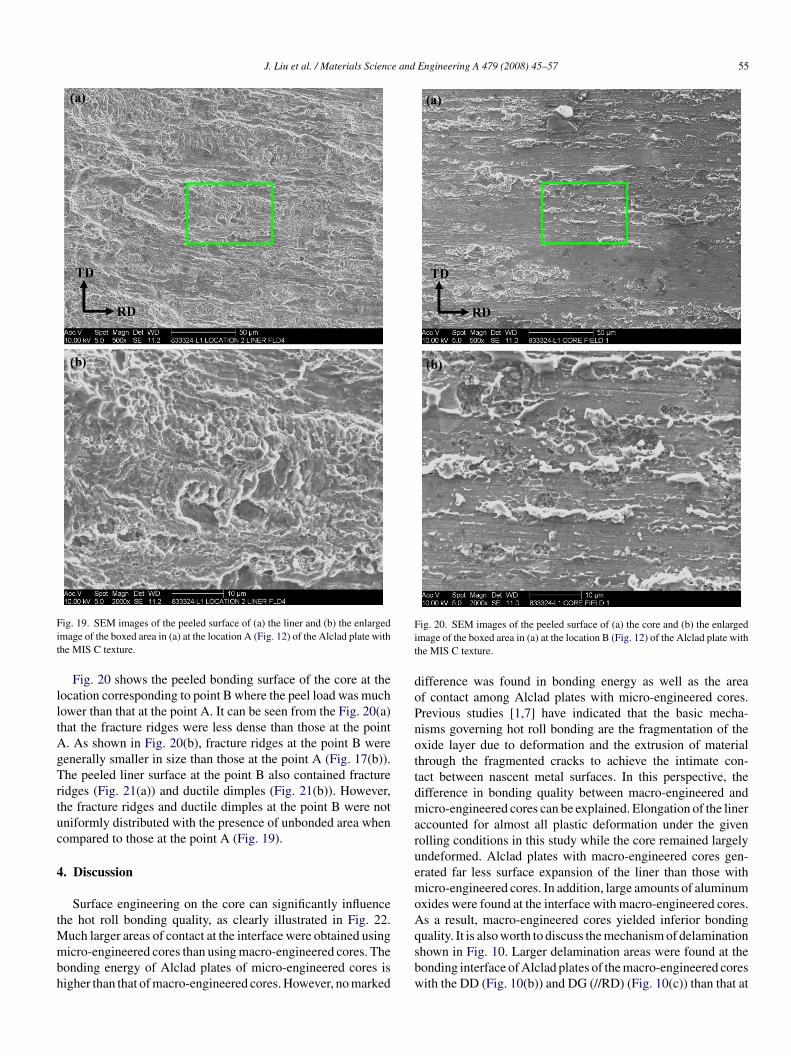
Fit
lltAgTrtuc
4
tMmbh
Fit
doPnottdmaruemoA
ig. 19. SEM images of the peeled surface of (a) the liner and (b) the enlargedmage of the boxed area in (a) at the location A (Fig. 12) of the Alclad plate withhe MIS C texture.
Fig. 20 shows the peeled bonding surface of the core at theocation corresponding to point B where the peel load was muchower than that at the point A. It can be seen from the Fig. 20(a)hat the fracture ridges were less dense than those at the point. As shown in Fig. 20(b), fracture ridges at the point B wereenerally smaller in size than those at the point A (Fig. 17(b)).he peeled liner surface at the point B also contained fracture
idges (Fig. 21(a)) and ductile dimples (Fig. 21(b)). However,he fracture ridges and ductile dimples at the point B were notniformly distributed with the presence of unbonded area whenompared to those at the point A (Fig. 19).
. Discussion
Surface engineering on the core can significantly influencehe hot roll bonding quality, as clearly illustrated in Fig. 22.
uch larger areas of contact at the interface were obtained usingicro-engineered cores than using macro-engineered cores. The
onding energy of Alclad plates of micro-engineered cores isigher than that of macro-engineered cores. However, no marked
qsbw
ig. 20. SEM images of the peeled surface of (a) the core and (b) the enlargedmage of the boxed area in (a) at the location B (Fig. 12) of the Alclad plate withhe MIS C texture.
ifference was found in bonding energy as well as the areaf contact among Alclad plates with micro-engineered cores.revious studies [1,7] have indicated that the basic mecha-isms governing hot roll bonding are the fragmentation of thexide layer due to deformation and the extrusion of materialhrough the fragmented cracks to achieve the intimate con-act between nascent metal surfaces. In this perspective, theifference in bonding quality between macro-engineered andicro-engineered cores can be explained. Elongation of the liner
ccounted for almost all plastic deformation under the givenolling conditions in this study while the core remained largelyndeformed. Alclad plates with macro-engineered cores gen-rated far less surface expansion of the liner than those withicro-engineered cores. In addition, large amounts of aluminum
xides were found at the interface with macro-engineered cores.s a result, macro-engineered cores yielded inferior bonding
uality. It is also worth to discuss the mechanism of delaminationhown in Fig. 10. Larger delamination areas were found at theonding interface of Alclad plates of the macro-engineered coresith the DD (Fig. 10(b)) and DG (//RD) (Fig. 10(c)) than that at
56 J. Liu et al. / Materials Science and En
Fig. 21. SEM images of the peeled surface of (a) the liner and (b) the enlargedimage of the boxed area in (a) at the location B (Fig. 12) of the Alclad plate withthe MIS C texture.
Fig. 22. The contact area in terms of mean amplitude (MA) used in ultrasonictest and the bonding energy as a function of the scale of the surface engineering.Energy was calculated based on the roller peeling length between 25 mm and122 mm.
tct“ottobd
wtpwuittndcpcrmbtaoatwdba
fbmfar
fitad
5
tMeri
gineering A 479 (2008) 45–57
he bonding interface of Alclad plates of the macro-engineeredores with the SD (Fig. 10(a)) and SG (//RD) (Fig. 10(d)) tex-ures. It appears that the metal of liner failed to fully fill in thevalleys” on the core and thus caused delamination. The linerf the Alclad plate using macro-engineered core with the DDexture (Fig. 14(b)) was deformed to a much less extent thanhat with the SD texture (Fig. 16(a)). Large intact surface areaf the core with the DD texture (Fig. 14(a)) suggests that noonding was ever established, which rules out the possibility ofelamination of initially bonded interface.
It has been shown that, in every case, the bonding interfaceas far from uniform. Unbonded areas were evident even at loca-
ions (e.g., the point A on the curve MIS C) where a very higheel load was observed. A thick layer of oxides was detectedith an estimated thickness of 320 nm on the surface of thenbonded area as marked by the red box in Fig. 17(a). This find-ng suggests that a thick layer of oxides is indeed correlated withhe unbonded area. A thick oxide layer is difficult to break andhus hinders the establishment of the intimate contact betweenascent metal surafces. Large amounts of fracture ridges anductile dimples (Fig. 17(a) and (b)) found in bonded areas indi-ated substantial local deformation at the interface during theeel test. As shown in Fig. 18, the bonded areas were found toontain only aluminum. These results suggest that these fractureidges and ductile dimples are originally from the liner that wasade of AA 1100 alloy. In bonded areas, the bonding strength
etween the core and the liner is even higher than the strength ofhe liner. Therefore, the liner was fractured during the peel testnd formed fracture ridges and ductile dimples on the surfacef the core. The thickness of the oxide layer in bonded areas,lthough important, is not known. No attempt has been madeo measure the thickness of the oxide layer in the bonded areashere the surface was covered by fracture ridges and ductileimples. Nevertheless, the thickness of the oxide layer in theonded areas is estimated to be less than that in the unbondedreas.
In this paper, we restricted our attention to the effect of sur-ace engineering on the bonding quality. In order to improveonding quality, control of the thickness of the oxide layer andicrostructure at the interface requires further exploration in
uture research. It should be realized that the bonding quality islso affected by many other factors such as rolling temperature,eduction, strain, strain rate, lubrication, etc.
Roll bonding of Alclad plates is a complicate process. 3Dnite element simulation can provide much needed insight into
his process, and to guide design of surface engineering with theim of optimizing the bonding process. Future work along thisirection warrants much attention.
. Conclusions
It has been demonstrated that the surface engineering onhe core significantly affects the hot roll bonding quality.
icro-engineering yields better bonding quality than macro-ngineering. Micro-engineered surface on the core with aoughness less than 0.58 �m results in high-quality roll bond-ng. However, no marked improvement is observed when the

e and
s0
mbsc
tt
R
[[
[[4] Y. Jiang, D. Peng, D. Lu, L. Li, J. Mater. Process. Technol. 105 (2000) 32–37.
J. Liu et al. / Materials Scienc
urface roughness of the core is reduced further to 0.13 �m and.03 �m.
The oxide layer on the surface of the core and the local defor-ation on the liner surface play important roles in affecting the
onding quality. Further improvement in bonding quality is pos-ible, provided that the thickness of oxide layer on the surface
an be well controlled.Ultrasonic testing has been shown to be capable of assessinghe bonding interface in a quantitative manner. The ultrasonicest results are in good agreement with roller peel test results.
[[
[
Engineering A 479 (2008) 45–57 57
eferences
1] N. Bay, J. Eng. Ind. Trans. ASME 101 (1979) 121–127.2] H.R. Madaah-Hosseini, A.H. Kokabi, Mater. Sci. Eng. A 335 (2002)
186–190.3] H.-Z. Yan, J.G. Lenard, Mater. Sci. Eng. A 385 (2004) 419–428.
5] H.D. Manesh, A.K. Taheri, Mater. Design 24 (2003) 617–622.6] G.-Y. Tzou, M.-N. Huang, J. Mater. Process. Technol. 140 (2003) 622–
627.7] J.A. Cave, J.D. Williams, J. Inst. Met. 101 (1973) 203–207.