pollution prevention in the magnetic tape industry: waterborne coating formulations for video tape...
TRANSCRIPT

Pergamon
0956-053X(95)00030-5
Waste Management, Vol. 15, No. 4, pp. 257-264, 1995 Copyright C 1995 Elsevier Science Ltd Printed in the USA. All rights reserved
0956-053X/95 $9.50 + 0.00
ORIGINAL CONTRIBUTION
POLLUTION PREVENTION IN THE MAGNETIC TAPE INDUSTRY: WATERBORNE COATING FORMULATIONS FOR VIDEO TAPE MANUFACTURE
Song Cheng, Hong Fan, Naveen Gogineni, Brent Jacobs, J. W. Harrell, I. A. Jefcoat, Alan M. Lane and David E. Nikles” The Center for Materials,for Information Technology, The University qf Alabama, Tuscaloosa, AL 35487-0209, U.S. A.
ABSTRACT. A waterborne magnetic tape coating formulation was designed and used to prepare experimental magnetic tape samples in a pilot coating trial. The formulations contained a blend of a water-dispersed polyester and an ethylene/vinyl chloride copolymer emulsion, cross-linked with melamine-formaldehyde to give tensile properties (tensile strength 8.69 MPa and Young’s modulus 245 MPa) that were comparable to a standard solvent-based binder composi- tion. The pilot tape trial used existing processing equipment, including calendering and slitting. The tape had good mag- netic properties and excellent adhesion between the pigmented magnetic layer and the base film, easily exceeding the 8 mm helical scan tape standard of 0.96 N peel force. An economic impact analysis for the case of using our waterborne video tape coating process in a conventional tape manufacturing plant showed a significant decrease in costs for adopting the waterborne process.
INTRODUCTION
In the information age magnetic tape is an important means of storing information and will play a major role in the information superhighway. Magnetic tape provides a low-cost, high-density information storage medium. The information may be stored in either analog or digital form and may comprise computer data, audio or video. In 1994 the worldwide revenue for flexible magnetic media, magnetic tape, and floppy disks, was expected to be 14 billion dollars with more than 2 billion T-120 video cassettes
RECEIVED 6 MARCH 1995; ACCEFTED 6 JUNE 1995. *To whom correspondence may be addressed. Acknowledgments - The assistance of Graham Magnetics, Graham, Texas, in conducting the pilot coating trial is very much appreciated. This project has been funded in part by the University of Alabama, with Federal Funds under the cooperative agreement CR 822961-o 1-O with the Risk Reduction Engineering Laboratory, United States Environmental Protection Agency and with Federal Funds as part of the program of the Gulf Coast Hazardous Substance Research Center which is supported under the cooperative agree- ment R815197 with the United States Environmental Protection Agency. The contents do not necessarily reflect the views and policies of the U. S. EPA nor does the mention of trade names or commercial products constitute endorsement or recommendation for use.
manufactured.’ The magnetic tape industry is multi- national with about l/3 of the world-wide manufac- turing capacity in the U.S., 3M being a leading tape manufacturer. There is a concentration of the flexible media industry in the Southern United States, with Ampex, JVC and Sony having major manufacturing operations in Alabama, TDK and Sony in Georgia, Fuji in South Carolina, and Graham Magnetics in Texas. Clearly, the magnetic tape industry is important to the United States and the U.S. has a strong interest in fostering the growth of this industry.
Magnetic tape consists of a polyester base film that has a magnetic coating on one of its surfaces.* The polyester base, also called a web, is an extruded, biaxially oriented polyethylene terephthalate film, typically 7-15 pm thick. The base film supports the magnetic coating and gives the tape the mechanical strength required for winding and unwinding during recording and reading. The magnetic coating con- tains magnetic pigments bound to the base film by a cross-linked binder. In magnetic tapes the pigment particles are oriented so that the axis of easy magne- tization lies parallel to the long direction of the tape. These magnetic particles store the information as magnetized domains in the tape. Early tapes used y-Fe,O, pigments. The current generation of magnetic
251
258 SONG CHENG ET AL.
tape products primarily use either y-Fe,O,, cobalt- modified -y-Fe,O,, chromium dioxide, or iron pig- ments, depending on the application (i.e. audio tape, video tape, or instrumentation tape). Future genera- tions of high performance tape will use either iron or barium ferrite pigments. The binders generally con- sist of a cross-linked blend of a polyurethane and a vinyl chloride copolymer. The binder is cross-linked with a polyisocyanate cross-linking agent. The com- bination of the polymer blend and the cross-linking agent produces a cured binder with the requisite flexibility, adhesion to the polyester base film, and toughness. The coating also contains additives (lubricants and alumina particles) that control the frictional properties of the head-tape interface. An anti-static agent, such as carbon black, may be included in the coating, or be part of a coating on the opposite side of the base film. The carbon black increases the conductivity of the tape and allows static electric charges to be dissipated. The demand for ever higher data capacity and data storage rates for magnetic tape drives the evolution of the materials package. The major changes come from the intro- duction of new magnetic pigment particles with better magnetic properties. These changes in magnetic pigments effect changes in the choice of binder poly- mers, dispersing agents, and other additives. There- fore, the tape industry is required to continually pursue research and development on the materials package for magnetic tape.
Magnetic tape is manufactured by a continuous web coating process. Polyester base film is coated with a fluid that contains a dispersion of the magnetic particles in a mixture of organic solvents. The fluid also contains dissolved binder polymers, cross-linking agents, lubricants, and other additives. The coating is applied by either reverse roll coating or direct gravure techniques. Immediately after coating, the wet film passes through a magnetic field that orients the pigment particles. The film then enters a drying oven, where it is dried under a stream of hot air. The web leaves the oven and is either wound onto a reel, or calendered on-line to compact the magnetic coating and smooth the surface. The cured, calen- dered web is then slit to the required width and wound onto a reel for packaging. Web coating is largely an art guided by a few scientific principles. The coating fluid must adequately wet the substrate and therefore the surface tension of the coating fluid must be less than the surface tension of the base film. The viscosity of the coating fluid should be high enough so that it does not run off the web, but low enough so that imperfections in the coating can be leveled out by surface tension forces. The coating must dry rapidly in the oven to allow for high web speed. However, the coating must also dry in a manner that gives smooth surfaces with a low level
of inhomogeneities that would otherwise contribute to increasing the noise and the number of data errors. As the materials package has evolved for magnetic media, so has the coating process.
Two significant pieces of environmental legislation were enacted in 1990 that have a direct impact on the magnetic tape industry - the Pollution Prevention Act and the Clean Air Act Amendments. Both of these apply pressure on the industry to seek alternative methods for applying the magnetic media to the tapes. The thrust of the Pollution Prevention Act is to reduce or prevent pollution at the source. This is to be done by encouraging industry to make changes in the production, operation, or use of raw materials in the manufacturing process. Congress and the EPA believe that source reduction is fundamentally different and more desirable than waste management and pollution control. The Clean Air Act Amend- ments, Title III, list 189 hazardous air pollutants, which include some of the solvents used by the mag- netic tape manufacturing industry. The EPA must identify all the sources of hazardous air pollutants within 12 months and promulgate regulations for the top 40 sources within 2 years. The magnetic tape manufacturing industry is within the top 40 sources. One of the major requirements of Title III is the MACT (maximum achievable control technology) provision. MACT will be determined based on the performance of the best five plants within the mag- netic tape manufacturing industry. The regulations have been published in the 1994 National Emissions Standards for Hazardous Air Pollutants.3 It is to the industries’ advantage to develop technologies that eliminate the use of solvents which are one of the 189 hazardous air pollutants and avoid having to apply this stringent control technology.
The organic solvents used in magnetic tape coating formulations include 2-butanone (MEK), 4-methyl- 2-pentanone (MIBK), tetrahydrofuran (THF), toluene, and cyclohexanone. These solvents present an occu- pational hazard to the workers and an emissions hazard to the environment. MEK, MIBK, and toluene are on the list of 189 hazardous air pollutants and on the list of 18 for the EPA’s 33/50 voluntary pollution reduction program.4 In modern tape manu- facturing plants the solvent vapors from the drier are recovered by use of a carbon bed adsorber. This is stripped by steam. The steam is condensed or is put through a distillation column. This allows recovery and reuse of the individual components. The coating operations are safe and the air emissions meet EPA standards. Considerable capital equipment is required to contain and recycle the organic solvents. Further- more, maintaining the emission prevention equipment adds complexity to the tape manufacturing process. With more stringent federal regulations on emission controls, tape manufacturers may be forced to
POLLUTION PREVENTION IN THE MAGNETIC TAPE INDUSTRY
install even more capital equipment to comply with the regulations. Alternatively, they may be forced to shut down their operations and move offshore. The U.S. cannot afford to lose manufacturing jobs, par- ticularly in a high technology industry that will play an important role in the information superhighway. If there were alternative magnetic tape coating pro- cesses that avoid using organic solvents, the consid- erable capital expense required in capturing the organic solvents would be eliminated. The industry would be in a better position to maintain compliance to any present or future emissions regulations. The concept of pollution prevention, instead of pollution control, would be realized.
The objective of our research program is to replace the organic solvents used in magnetic tape with water, thereby preventing pollution. The goal of waterborne magnetic coating formulations requires the identification of dispersing agents, binders, and lubricants that are compatible with water. This has led to a search for commercial coating materials that could be used in this application. The focus on com- mercial materials would allow research success to be rapidly taken forward to commercialization. Initial experimentation focused on video tape formulations, containing cobalt-modified y-FeZ03 pigment, because of the large video tape market. Replacement of the organic solvents in video tape coating plants would have the greatest pollution prevention impact. In this paper we describe our waterborne coating for- mulations and the results of a pilot coating trial where magnetic tape was prepared. The results of an economic and environmental impact analysis of replacing a solvent-based tape coating process with a waterborne process are also reported.
WATERBORNE COATING FORMULATIONS
The binder films used in modern magnetic tapes are generally blends of a thermoplastic polyurethane and a polyvinyl chloride, cross-linked with a poly- isocyanate. The oil and energy crises of the 1970s and 1980s saw a dramatic increase in the cost of organic solvents. This, coupled with more stringent air emission standards, led the industry to examine the use of waterborne coating formulations for mag- netic tape manufacture. Formulations were devel- oped and successfully used to prepare magnetic tape. At that time the industry made the business decision to continue using solvent-based tape coating pro- cesses and invest in the pollution control equipment needed to meet air emission standards. Very little of the work has been reported in the literature, mostly in the form of patents. There are examples of water- borne coating formulations containing acrylic latex binders.5 An aqueous coating formulation containing cyclic sulfonium zwitterion monomers has been
reported.6 This formulation was cured by moderate heating which polymerized the monomers to form a binder. More recently a water-dispersible polyurethane binder has been disclosed.: Polyfunctional aziridine cross-linking agents for aqueous magnetic coating formulations have also been reported.x In view of the Clean Air Act Amendments, our objective here is to stimulate the tape industry to re-examine the use of waterborne coating formulations.
Our first task was to identify latexes or emulsions that were suitable as binders for the waterborne for- mulations. The latex must be compatible with the other ingredients of the formulation. It must be stable under the high shear conditions experienced during milling. The tensile properties and adhesion to the polyester base film must meet or exceed those of commercial solvent-based binder systems. A number of commercial latexes or emulsions were screened. Carboxylated styrene-butadiene latexes and neoprene latexes were unstable under high shear and coagu- lated during milling. An acrylic latex (Rhoplex WP-76 from Rohm and Haas) gave pigmented films with poor adhesion to the polyester base film. The best binder was either a blend of a polyester (Bayhydrol B-130 from Miles) and an ethylene-vinyl chloride copolymer emulsion (Vancryl 610 from Air Products and Chemicals), or a polyurethane emulsion (Cydro- thane HP5035 from Cytech Industries). Both were cross-linked with a waterborne melamine-formalde- hyde resin (Cymel 385 from Cytech Industries). Bay- hydrol B-l 30 is a self-emulsified polyester with terminal alcohol groups that provide sites for cross- linking. Vancryl 610 is a vinyl chloride-ethylene copolymer emulsion which contains a small amount of acrylamide, the amide functionality providing a site for cross-linking. All were stable under the high shear conditions experienced during milling. Cymel 385 was chosen for its ability to act as a cross-linker at moderate temperatures, less than 80°C.
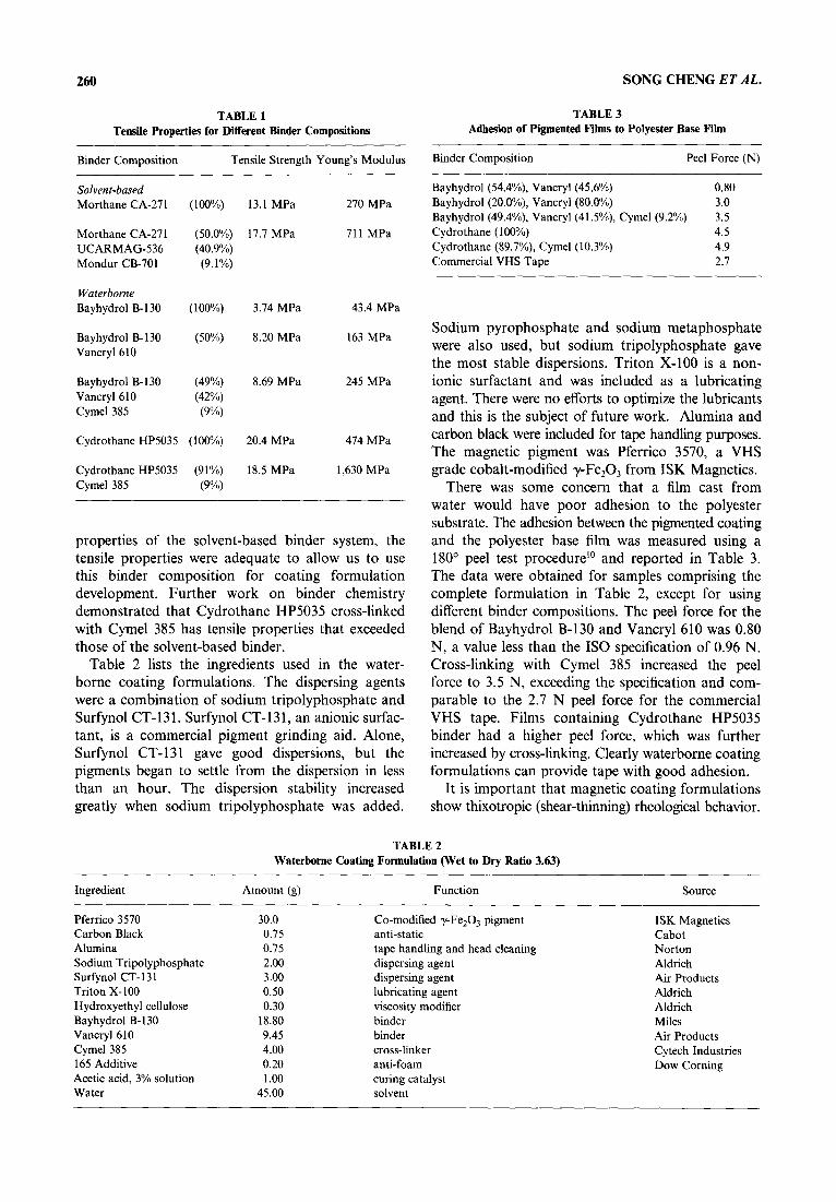
Films of the binder resins were prepared by casting onto glass plates, drying for 18 h at 6O”C, and lifting from the plates. The tensile properties of the unpig- mented binder films were measured on an Instron Universal Tensile Tester using an ASTM procedure” and are listed in Table 1. Our objective was to match or exceed the tensile properties of a commer- cial solvent-based binder system, containing a blend of Morthane CA-27 1 (a thermoplastic polyurethane from Morton International), UCARMAG-536 (a polyvinyl chloride wetting binder from Union Car- bide) and Mondur CB-701 (a polyisocyanate cross- linker from Miles). Alone, Bayhydrol B-130 did not have adequate tensile properties, however blending with Vancryl 610 doubled the tensile strength and almost quadrupled the modulus. Further improvements in tensile properties resulted from cross-linking with Cymel 385. Although this did not match the tensile
260 SONG CHENG ET AL.
TABLE 1 Tensile Properties for Different Binder Compositions
TABLE 3 Adhesion of Pigmented Films to Polyester Base Film
Binder Composition Tensile Strength Young’s Modulus
Solvent-based Morthane CA-271 (100%) 13.1 MPa 270 MPa
Morthane CA-271 (50.0%) 17.7 MPa 711 MPa UCARMAG-536 (40.9%) Mondur CB-701 (9.1%)
Waterborne Bayhydrol B-130 (100%) 3.74 MPa 43.4 MPa
Bayhydrol B-130 (50%) 8.20 MPa 163 MPa Vancryl 610
Binder Composition Peel Force (N)
Bayhydrol (54.4%), Vancryl (45.6%) 0.80 Bayhydrol (20.0%), Vancryl (80.0%) 3.0 Bayhydrol (49.4%), Vancryl (41.5%) Cymel (9.2%) 3.5 Cydrothane (100%) 4.5 Cydrothane (89.7%), Cymel (10.3%) 4.9 Commercial VHS Tape 2.7
Bayhydrol B-130 Vancryl610 Cyme1385
(49%) (42%) (9%)
8.69 MPa 245 MPa
Cydrothane HP5035 (100%) 20.4 MPa 474 MPa
Cydrothane HP5035 (91%) 18.5 MPa 1,630 MPa Cymel 385 (9%)
Sodium pyrophosphate and sodium metaphosphate were also used, but sodium tripolyphosphate gave the most stable dispersions. Triton X-100 is a non- ionic surfactant and was included as a lubricating agent. There were no efforts to optimize the lubricants and this is the subject of future work. Alumina and carbon black were included for tape handling purposes. The magnetic pigment was Pferrico 3570, a VHS grade cobalt-modified -y-Fe,O, from ISK Magnetics.
properties of the solvent-based binder system, the tensile properties were adequate to allow us to use this binder composition for coating formulation development. Further work on binder chemistry demonstrated that Cydrothane HP5035 cross-linked with Cymel 385 has tensile properties that exceeded those of the solvent-based binder.
Table 2 lists the ingredients used in the water- borne coating formulations. The dispersing agents were a combination of sodium tripolyphosphate and Surfynol CT- 13 1. Surfynol CT- 13 1, an anionic surfac- tant, is a commercial pigment grinding aid. Alone, Surfynol CT-131 gave good dispersions, but the pigments began to settle from the dispersion in less than an hour. The dispersion stability increased greatly when sodium tripolyphosphate was added.
There was some concern that a film cast from water would have poor adhesion to the polyester substrate. The adhesion between the pigmented coating and the polyester base film was measured using a 180” peel test procedure’O and reported in Table 3. The data were obtained for samples comprising the complete formulation in Table 2, except for using different binder compositions. The peel force for the blend of Bayhydrol B-130 and Vancryl 610 was 0.80 N, a value less than the IS0 specification of 0.96 N. Cross-linking with Cymel 385 increased the peel force to 3.5 N, exceeding the specification and com- parable to the 2.7 N peel force for the commercial VHS tape. Films containing Cydrothane HP5035 binder had a higher peel force, which was further increased by cross-linking. Clearly waterborne coating formulations can provide tape with good adhesion.
It is important that magnetic coating formulations show thixotropic (shear-thinning) rheological behavior.
TABLE 2 Waterborne Coating Formulation (Wet to Dry Ratio 3.63)
Ingredient Amount (g) Function Source
Pferrico 3570 Carbon Black Alumina Sodium Tripolyphosphate Surfynol CT-l 3 1 Triton X-100 Hydroxyethyl cellulose Bayhydrol B- 130 Vancryl 610 Cymel 385 165 Additive Acetic acid, 3% solution Water
30.0 Co-modified -+Fe203 pigment 0.75 anti-static 0.75 tape handling and head cleaning 2.00 dispersing agent 3.00 dispersing agent 0.50 lubricating agent 0.30 viscosity modifier
18.80 binder 9.45 binder 4.00 cross-linker 0.20 anti-foam 1 .oo curing catalyst
45.00 solvent
ISK Magnetics Cabot Norton Aldrich Air Products Aldrich Aldrich Miles Air Products Cytech Industries Dow Corning

POLLUTION PREVENTION IN THE MAGNETIC TAPE INDUSTRY 261
~~~~,‘“i,““““““‘:“““‘~“‘:“’ b
- Solvent-Based ‘. 3mi :: - * - Waterborne. 0.0 g hydmxyethyl cellulose
2500~ : : -8- Waterborne. 0.40 g hydroxeythyl cellulose
p g
-A Waterborne. 0.80 g hydroxethyl cellulose
F m; ::
-100 0 IW 200 300 400 500 600 700 800
Shear Rate (s ‘)
FIGURE 1. A comparison of the rheology of a solvent-based formulation and waterborne formulations. The effect of added hydroxyethyl cellulose on the rheology of the waterborne formulation listed in Table 2.
Low viscosity at high shear allows the fluid to be spread over the web during coating and high viscos- ity at low shear prevents the coating from running off the web as it travels down the coating line. In Fig. 1 are plots of the viscosity as a function of shear rate for a conventional solvent-based coating formulation and our waterborne coating formulation. The solvent-based formulation shows a high value of viscosity under low shear rate, while the waterborne formulation shows low viscosity at low shear stress. The high viscosity in the solvent-based formulation arises from chain entanglements between dissolved binder polymers. The binder polymers in the water- borne emulsions are in spherical aggregates with no possibility of chain entanglements between the spheres. Therefore it was expected that the water- borne coating formulation would have low viscosity. Adding small amounts of hydroxyethyl cellulose, a water soluble polymer, increased the low shear viscosity, giving coating fluids with good rheological behavior, Fig. 1. However, there was some concern about the effect of hydroxyethyl cellulose on the
c
-100 loo 300 500 700 xl0 1100 1300
Shear Rate (s.‘)
FIGURE 2. Rheology of the improved waterborne formulation listed in Table 4.
tensile properties of the binder and on the long-term stability of the tape. Hydroxyethyl cellulose, being hydrophilic, may cause moisture sensitivity in long- term storage. Therefore, we decided to remove the hydroxyethyl cellulose and make other modifications to the formulation. The result was a new formulation, Table 4, with acceptable rheological properties, Fig. 2. The low viscosity inherent in waterborne coating formulations was actually an important benefit because formulations with higher solids can be pre- pared. The higher solids level means less coating fluid was required for the same dry film thickness. Furthermore less solvent must be removed in the drier. These were important factors in the cost of the waterborne coating process, as will be shown below.
PILOT COATING TRIAL
Experimental tape samples were prepared in a pilot coating trial at Graham Magnetics, Graham, Texas. The formulation was prepared with conventional mixing and milling equipment. The dispersion was
TABLE 4 Improved Waterborne Coating Formulation (Wet to Dry Ratio 3.65)
Ingredient Amount (g) Function Source
Pferrico 3570 Carbon Black
47.40 Co-modified y-Fe,O, pigment ISK Magnetics
1.75 anti-static Cabot
Alumina 1.00 Surfynol CT- 13 I 4.00 Surfynol I IOD 1.50 Surfynol 504 0.75 Surfynol 104A 0.75 Bayhydrol B-130 24.00 Vancryl 610 12.50 Cymel 385 3.50 1% Polyhydron 1.75 Water 60.00
tape handling and head cleaning dispersing agent anti-foam anti-foam anti-foam binder binder cross-linker pH 2.00 buffer, curing catalyst solvent
Norton Air Products Air Products Air Products Air Products Miles Air Products Cytech Industries Aldrich

262 SONG CHENG ET AL.
TABLE 5 Magnetic Characterizations of the Tape Samples Prepared in the
Pilot Tape Coating Trial
Sample HSGe) SQ SFD cx
Pass 1 567 0.80 0.35 -0.369 Pass 2 605 0.85 0.43 -0.347 Pass 3 603 0.85 0.43 PO.334 Pass 4 611 0.86 0.40 -0.327 Pass 5 612 0.86 0.40 -0.288 Pass 6 603 0.86 0.40 -0.292 Pass I 615 0.86 0.40 PO.261 Pass 8 615 0.86 0.42 -0.321 Pilot Tape 570 0.81 0.38 -0.360 Worst Pilot Tape 518 0.60 0.54 -0.541 Commercial VHS 669 0.78 0.38 -0.286
passed through a sand mill, a sample taken and hand draw-down samples were prepared. The mag- netic properties of these samples were characterized. After eight passes through the mill, the dispersion was ready for coating. A 5-inch (12.5 cm) knife coater was used with a web speed of 15-18 m/min. The coating was dried in an 18-foot (5.4 m) long conventional oven, the dried tape calendered to give a high gloss finish (gloss number 106) and then slit into 0.5 inch (1.25 cm) widths. The trial was largely successful. Tape was prepared from our waterborne coating formulation using existing piloting equip- ment. However, the pilot trial revealed a pinhole defect problem, not encountered when preparing laboratory hand draw-down samples. These pinholes were attributed to foaming and a dynamic wetting problem during coating. Experiments were directed at solving this problem; the new formulation listed in Table 4 included anti-foam agents that solved the defect problem.
hand drawn samples, for a sample prepared on the pilot coater and for a commercial VHS tape. Also reported are values of the interparticle interaction field parameter, (Y, obtained from magnetic remanence curves. A direct comparison of dispersion quality cannot be made between the waterborne coating and the VHS tape since the pigments and the packing fractions are not the same. High values of square- ness and coercivity indicate a well-oriented tape, while well-dispersed pigments would display small values of (Y, the ideal values being zero. As expected, the squareness and coercivity increased as the num- ber of passes increased until the values leveled off, indicating the dispersion quality had reached a maximum. For the tape samples the value of (Y increased with increasing number of passes. The values of (Y were negative, indicating that the interparticle interactions were demagnetizing, as expected for acicular particles. The values of squareness and (Y for the pilot tape were lower than those for the hand drawn samples. This suggests that more experimen- tation on the pilot coater is required to optimize the magnetic properties. The pilot tape had a higher squareness than the commercial VHS tape, but it had a lower value of CL It was encouraging that the magnetic properties of tape from the waterborne dispersion were comparable to those for the com- mercial VHS tape.
ECONOMIC AND ENVIRONMENTAL IMPACT ANALYSIS
The magnetic properties of the tape prepared in the pilot trial were reported in detail elsewhere.” In Table 5 are reported the values of coercivity (H,), squareness (SQ) and switching field distribution (SFD) from magnetic hysteresis loops for the eight
The materials and energy costs of waterborne mag- netic tape coating processes were compared to a conventional solvent-based process. The objective was to determine the economic incentive to convert an existing solvent-based process to a waterborne process. The study was limited to video tape with a 2.00 pm dry film thickness, 1.22 m web width, and 600 mimin output. The waterborne formulations in Tables 2 and 4 and the solvent-based formulation in Table 6 were compared.
TABLE 6 Typical Organic Solvent-based Formulation (Wet to Dry Ratio 9.66)
Ingredient Amount (g) Function source
Pferrico 3570 100.0 Carbon Black 2.00 Alumina 6.00 Butyl Stearate 1.25 Stearic Acid 1.25 UCARMAG-536 11.25 Morthane CA-271 13.75 Mondur CB-701 2.50 Tetrahydrofuran 64.30 2-Butanone 126.36 Toluene 126.47
Co-modified -y-Fe,O, pigment anti-static tape handling and head cleaning lubricating agent lubricating agent wetting binder binder cross-linker solvent solvent solvent
ISK Magnetics Cabot Norton Aldrich Chemical Aldrich Chemical Union Carbide Morton International Miles
POLLUTION PREVENTION IN THE MAGNETIC TAPE INDUSTRY
TABLE 7 TABLE 9 Comparison of the Material and Energy Costs per Hour of
Operation at 600 m/min Web Speed with a Dry Film Thickness of 2.0 ym
Hourly Material Costs for the Solvent-based Coating Process Running at f500 m/min Web Speed
Formulation Materials Energy Cost Cost for
cost for Dryer Recycling Total
Solvent-based, Table 5 $1570 Waterborne, Table 2 11002 Waterborne, Table 4 $1170 Waterborne, Table 4, $1413 with higher pigment
$7.69 $13.56 $1592 $15.58 50.00 $1018 $15.65 SO.00 $1186 $12.89 $0.00 $1426
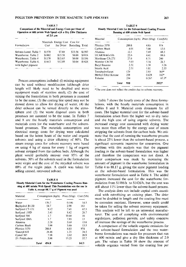
Process assumptions included: (1) existing equipment can be used without modification (although drier length will likely need to be doubled and more equipment made of stainless steel), (2) the cost of mixing the formulation in both processes is assumed to be the same, (3) the coating line speed may not be slowed down to allow for drying of water, (4) the drier exhaust can be vented directly to the atmo- sphere and (5) the waste disposal costs in both processes are assumed to be the same. In Tables 7 and 8 are the hourly materials consumption and materials costs for the waterborne and the solvent- based processes. The materials consumption and electrical energy costs for drying were calculated based on the latent heats of the water and organic solvents and using a drier efficiency of 80%. The steam energy costs for solvent recovery were based on using 4 kg of steam for every 1 kg of organic solvent stripped from the carbon beds. Although the plant would probably recover over 95% of the solvents. 50% of the solvents used in the formulation were virgin and the cost of the recycled solvent was 60% of the virgin price. A credit was taken for selling unused, recovered solvent.
TABLE 8 Hourly Material Costs for the Waterborne Coating Process Run- ning at 600 m/min Web Speed: This Formulation was the one in
Table 4, except 88.17 g of Pigment was used
Material Consumption (kg/h) Price (S/kg) Cost (S/h)
Water 136.7 0.106 Bayhydrol B- 130 54.1 2.98 Surfynol CT- I3 1 9.12 7.41 Surfynol 1 IOD 3.41 8.42 Surfynol504 1.7 10.69 Surfynol 104A 1.7 7.85 Alumina 2.28 5.69 Carbon Black 3.98 3.40 Pferrico 3570 200.8 4.85 Vancryl 6 IO 28.46 1.21 Cymel 38.5 7.98 2.62 1% Polyhydron 3.98 13.25
Total 454.8
14.5 163 67.5 28.7 18 13 13.0 13.5
974 34.5 20.9 52.7
1413
Material Consumption (kg/h) Price (S/kg) Cost($/h)
Pferrico 3570 200.8 4.85 974 Carbon Black 4.01 3.40 13.6 Alumina 12.1 5.69 68.5 UCARMAG-536 22.6 4.41 99.6 Morthane CA-271 27.6 8.71 240 Mondur CB-701 5.03 5.18 26.1 Butyl Stearate 2.51 1.30 3.26 Stearic Acid 2.51 I.01 2.53 Tetrahydrofuran 129 2.83 365* Methyl Ethyl Ketone 258 0.628 l62* Toluene 254 0.265 61.3*
Total 918 2022x
*The cost does not reflect the credits due to solvent recovery.
Table 7 shows the hourly costs of the three formu- lations, with the hourly materials consumption in Tables 8 and 9. Material costs dominate for all cases. The higher material cost for the solvent-based formulation arises from the higher wet to dry ratio and the high cost of using organic solvents. The increased energy cost associated with drying water was more than offset by the energy cost of steam stripping the solvents from the carbon beds. We esti- mate that the cost of running the waterborne process is about 25% lower than the solvent-based process, a significant economic incentive for conversion. One problem with this analysis was that the pigment loading in the solvent-based formulation was higher and therefore the comparison was not direct. A fairer comparison was made by increasing the amount of pigment in the waterborne formulation in Table 4 to 88.17 g, giving the same pigment loading as the solvent-based formulation. This was the waterborne formulation used in Table 8. The added pigment increased the cost for the waterborne for- mulation from $1186/h to $1426/h, but the cost was still about 11% lower than the solvent-based process.
The analysis does not include capital costs associ- ated with retrofitting an existing plant. The drier must be doubled in length and the coating line must be corrosion resistant. However, some credit could be taken for selling the solvent recovery equipment. This analysis will be left to an interested manufac- turer. The cost of complying with environmental regulations, pollution permits, and safety concerns all increase the savings of the waterborne process.
A comparison of the volatile organic emissions for the solvent-based formulation and the two water- borne formulations was made for processes that run at 600 m/min and give a dry film thickness of 2.0 pm. The values in Table 10 show the amount of volatile organics vented from the coating line per

264 SONG CHENG ET AL.
TABLE 10 Comparison of the Potential Emissions per hour of Operation at
600 m/min Web Speed
Amount (kg/h)
Solvent-based, Table 5 Tetrahydrofuran 2-Butanone Toluene
Waterborne, Table 2
129 258 254
Formaldehyde Methanol
Waterborne, Table 4
0.075 7.35
Formaldehyde 0.048 Methanol 4.71
coating trial. The tape has mechanical and magnetic properties comparable to those of commercial VHS tape. There is a clear economic and environmental incentive to consider adopting this waterborne process for magnetic tape manufacture. This is not a commercial process and a development effort by a tape manufacturer is required to bring this process to commercial reality. We have not addressed the important issue of long-term reliability of the materials package, an object of current research. However, we have made a case for a re-examination of the use of waterborne coating formulations by the magnetic tape industry.
REFERENCES
hour. In the solvent-based process more than 600 kg of solvent per hour must be captured and recycled. The emissions from the waterborne process arose from the melamine-formaldehyde cross-linker, Cymel 385. Cymel 385 contained 0.5% free formaldehyde and the values in the table assumed all of the free formaldehyde ended up in the drier exhaust. During curing the melamine-formaldehyde cross-linker releases methanol and the value reported in Table 10 assumes all the methanol equivalents were released. A systematic study of the curing chemistry and kineticsI has shown that not all the methanol equivalents were released during curing and so these values present the worst case. Attempts to determine the formaldehyde and methanol content of the drier exhaust by GC mass spectroscopy were not successful. Traces of formaldehyde and methanol were detected, but the quantity could not be reliably determined due to the large amount of water present. No other volatile com- ponents were detected. The amounts of formaldehyde and methanol from the waterborne process are small and fall below the regulated limits. This enables venting of the drier exhaust directly to the atmosphere. The use of local ventilation with carbon bed adsorberi condenser could further reduce emission values.
1.
2.
3.
4.
5.
6.
I.
8.
CONCLUSIONS
9.
10.
11.
12.
We have developed a new waterborne coating formulation and prepared magnetic tape in a pilot
Lueck, L. B. Magnetic Media International Newsletter XII (5): l-43 (1991). Koster, E. and Arnoldussen, T. C. In: Magnetic Recording, Mee, C. D. and Daniel, E. D. (eds), Vol I: Technology, pp 98-243. McGraw-Hill: New York (1987). Environmental Protection Agency. National Emission Stan- dards for Hazardous Air Pollutant Emissions from Magnetic Tape Manufacturing Operations. Federal Register 59: 64580- 64612 (1994). Thayer, A. M. Growing exchange of information spurs pollution prevention efforts. Chem. Engng News 71: 8-25 (1993). (a) Denk, H. H. and Sabad, J. S. Magnetic coating compositions. U.S. Patent 3,725,285 (1975); (b) DiMino, A. Water-based binder for magnetic tape. U.S. Patent 3,79.5,539 (1974). Thomas, M. R., Lalk, R. H., Evani, S., and Schmidt, D. L. Magnetic tape and process of making a magnetic tape. U.S. Patent 3,976,822 (1976). Hampton, G. J. and Maida, W. F. Aqueous coating compo- sition and method. U.S. Patent 4,263,188 (1981). Pendergrass, D. B. Polyfunctional aziridine crosslinking agents for aqueous magnetic recording media binder. U.S. Patent 4,490,505 (1984). ASTM Designation D 882-911, Standard test methods for tensile properties of thin plastic sheeting. ISO/lEC DIS 10779. 8 mm wide magnetic tape cartridge for information interchange - helical scan recording. Secretariat ISOiIEC JTC l/SC 11, ANSI, 1430 Broadway, New York. Cheng, S., Fan, H., Harrell, J. W., Lane, A. M., and Nikles, D. E. Dispersion quality of magnetic tapes prepared from a waterborne formulation. IEEE Trans. Magnetics 30: 407111073 (1994). Cheng, S. Studies on Curing Chemistry and Properties of Wastebourne Coating Formulations for Magnetic Video Tapes. M.S. Thesis, The University of Alabama, Tuscaloosa, Alabama (1995).