pololu - pololu m3pi user's guide
TRANSCRIPT

Pololu m3pi User's Guide
1. Overview . . . . . . . . . . . . . . . . . . . . . . . . . . . . . . . . . . . . . . . . . . . . . . . . . . . . 21.a. Contacting Pololu . . . . . . . . . . . . . . . . . . . . . . . . . . . . . . . . . . . . . . . . . . . . 31.b. Included Components . . . . . . . . . . . . . . . . . . . . . . . . . . . . . . . . . . . . . . . . . . 31.c. Other Things You Might Need . . . . . . . . . . . . . . . . . . . . . . . . . . . . . . . . . . . . . 5
2. Assembly . . . . . . . . . . . . . . . . . . . . . . . . . . . . . . . . . . . . . . . . . . . . . . . . . . . . 82.a. Adding Components to the Top of the Expansion PCB . . . . . . . . . . . . . . . . . . . . . . . . . 82.b. Connecting the m3pi Expansion Board to the 3pi Robot . . . . . . . . . . . . . . . . . . . . . . . . 13
3. Using the m3pi . . . . . . . . . . . . . . . . . . . . . . . . . . . . . . . . . . . . . . . . . . . . . . . . . 173.a. mbed in Control . . . . . . . . . . . . . . . . . . . . . . . . . . . . . . . . . . . . . . . . . . . . . 173.b. Wixel in Control . . . . . . . . . . . . . . . . . . . . . . . . . . . . . . . . . . . . . . . . . . . . . 183.c. 3pi in Control . . . . . . . . . . . . . . . . . . . . . . . . . . . . . . . . . . . . . . . . . . . . . . 19
4. The Expansion Board in Detail . . . . . . . . . . . . . . . . . . . . . . . . . . . . . . . . . . . . . . . . . 204.a. mbed and Wireless Module Sockets . . . . . . . . . . . . . . . . . . . . . . . . . . . . . . . . . . 204.b. Power . . . . . . . . . . . . . . . . . . . . . . . . . . . . . . . . . . . . . . . . . . . . . . . . . . 254.c. Pushbuttons . . . . . . . . . . . . . . . . . . . . . . . . . . . . . . . . . . . . . . . . . . . . . . . 254.d. General-Purpose Voltage Dividers and MOSFET Circuits . . . . . . . . . . . . . . . . . . . . . . . 264.e. LEDs . . . . . . . . . . . . . . . . . . . . . . . . . . . . . . . . . . . . . . . . . . . . . . . . . . 264.f. Charge Port . . . . . . . . . . . . . . . . . . . . . . . . . . . . . . . . . . . . . . . . . . . . . . . 274.g. AVRISP Connector . . . . . . . . . . . . . . . . . . . . . . . . . . . . . . . . . . . . . . . . . . . 284.h. USB A Connector . . . . . . . . . . . . . . . . . . . . . . . . . . . . . . . . . . . . . . . . . . . . 294.i. 3pi Base Pins . . . . . . . . . . . . . . . . . . . . . . . . . . . . . . . . . . . . . . . . . . . . . . . 294.j. Prototyping Space . . . . . . . . . . . . . . . . . . . . . . . . . . . . . . . . . . . . . . . . . . . . 314.k. m3pi Schematic Diagram . . . . . . . . . . . . . . . . . . . . . . . . . . . . . . . . . . . . . . . . 32
Pololu m3pi User's Guide © 2001–2011 Pololu Corporation
http://www.pololu.com/docs/0J48 Page 1 of 32

Pololu 3pi robot on a 3/4" blackline.
1. OverviewThe m3pi robot is an upgraded version of our popular 3pi robot [http://www.pololu.com/catalog/product/975], consistingof a 3pi robot base connected to an m3pi expansion board that simplifies augmenting your robot’s capabilities withan mbed development board [http://www.pololu.com/catalog/product/2150] (or other microcontroller boards), wirelessmodules, and sensors.
The m3pi is available as a fully assembled robot [http://www.pololu.com/catalog/product/2151] (with the 3pi robot baseincluded) or as an expansion kit [http://www.pololu.com/catalog/product/2152] that can be used to turn a 3pi robot intoan m3pi robot.
Since the m3pi robot is an expansion of the 3pi robot, it also has all thefeatures of the 3pi robot:
• Max speed of around 100 cm/second
• Regulated motor voltage (performance is unaffected by batteryvoltage)
• 5 reflectance sensors on underside of leading edge for line followingand maze solving
• 8×2 character LCD for debugging, feedback, and user interfaces
• Piezo buzzer for simple sounds and music
Please see the 3pi robot product page [http://www.pololu.com/catalog/product/975] for a more comprehensive description the 3pi’s features and3pi resources (user’s guide, projects, videos, etc).
The rest of this user’s guide will help you get started with your m3pi robot or expansion kit.
Pololu m3pi User's Guide © 2001–2011 Pololu Corporation
1. Overview Page 2 of 32

Fully-assembled Pololu m3pi robot.
Hardware included with the Pololu m3pirobot.
1.a. Contacting PololuThank you for your interest in the m3pi robot [http://www.pololu.com/catalog/product/2151] or m3pi expansion kit for the 3pi robot[http://www.pololu.com/catalog/product/2152]. If you need technical support forthis product or have any feedback you would like to share, you cancontact us [http://www.pololu.com/contact] directly or post on our forum[http://forum.pololu.com/viewforum.php?f=29]. We would also be delighted tohear from you about any of your projects and about your experience withthe m3pi robot. Tell us what we did well, what we could improve, whatyou would like to see in the future, or anything else you would like to say!
1.b. Included ComponentsThe m3pi is available fully assembled with a 3pi robot base [http://www.pololu.com/catalog/product/2151] or as anexpansion kit for the 3pi robot [http://www.pololu.com/catalog/product/2152].
Fully-Assembled m3pi Robot with mbed SocketThe following connectors and components are already installedon the fully-assembled m3pi robot (as shown in the picture onthe right):
• mbed socket
• XBee socket
• USB A connector
• 2-pin battery-charging header
• Power pushbutton
• Two general-purpose pushbuttons
• 6-pin shrouded ISP connector
• All of the pins needed to connect to the 3pi robot base(male headers on the expansion PCB and matching femaleheaders on the 3pi base)
The fully-assembled m3pi robot also includes some optionalhardware and connectors:
• One 1×11 0.1″ female header [http://www.pololu.com/catalog/product/1021] and one 1×12″ female header[http://www.pololu.com/catalog/product/1030] for adding a Wixelsocket to the m3pi
• Three red shorting blocks [http://www.pololu.com/catalog/product/971], three yellow shorting blocks[http://www.pololu.com/catalog/product/969], and three blackshorting blocks [http://www.pololu.com/catalog/product/970] (the3pi base ships with three blue shorting blocks[http://www.pololu.com/catalog/product/968] already in place)
Pololu m3pi User's Guide © 2001–2011 Pololu Corporation
1. Overview Page 3 of 32

Pololu m3pi expansion kit.
• Two red LEDs [http://www.pololu.com/catalog/product/1070] and two green LEDs [http://www.pololu.com/catalog/product/1071]
• One 12″, 6-pin ISP cable [http://www.pololu.com/catalog/product/972]
m3pi Expansion Kit for 3pi RobotThe m3pi expansion kit PCB has all of thesurface-mount components populated, butnone of the through-hole components shipsoldered in. When combined with a 3pirobot [http://www.pololu.com/catalog/product/975](not included), the m3pi expansion kitincludes everything required to make yourown fully-assembled m3pi robot as picturedin the section above. These components areshown in the picture on the right and include:
• Two 2×20 0.1″ female headers foradding an mbed socket
• One 1×11 0.1″ female header[http://www.pololu.com/catalog/product/1021]and one 1×12″ female header[http://www.pololu.com/catalog/product/1030]for adding a Wixel socket
• Two 1×10 2mm female headers foradding an XBee socket
• One extended 2×7 0.1″ male header [http://www.pololu.com/catalog/product/1115] and two extended 1×2 0.1″male headers [http://www.pololu.com/catalog/product/1114] for connecting the expansion PCB to a 3pi base
• One 2×7 0.1″ female header [http://www.pololu.com/catalog/product/1027] and one 1×2 0.1″ female header[http://www.pololu.com/catalog/product/1012] for soldering to the 3pi base so it can accept the male connectors ofthe m3pi expansion PCB
• One 1×2 0.1″ female header [http://www.pololu.com/catalog/product/1012] for use as a charge port on theexpansion PCB
• Three 1×2 0.1″ male headers [http://www.pololu.com/catalog/product/965] for use with shorting blocks[http://www.pololu.com/catalog/product/968] for optional configuration of m3pi PCB connections (three blueshorting blocks are also included)
• One 6-pin shrouded ISP connector [http://www.pololu.com/catalog/product/854] that can be used with theincluded 12″, 6-pin ISP cable [http://www.pololu.com/catalog/product/972] to optionally let the mbed program the3pi base
• One USB A connector (can be used when the mbed is acting as a USB host)
• Three pushbuttons [http://www.pololu.com/catalog/product/1400] for use as a power button and two general-purpose buttons on the expansion PCB
• Four screws, spacers, and nuts for mounting the expansion PCB to the 3pi base
Pololu m3pi User's Guide © 2001–2011 Pololu Corporation
1. Overview Page 4 of 32

Pololu m3pi robot with mbed and Wixelmodules socketed.
1.c. Other Things You Might NeedThe m3pi is designed to be easily augmented by several additional components that are not included with them3pi:
• 4 AAA batteries. Any AAA cells will work, but we strongly recommend NiMH batteries, which arerechargeable and can be purchased from Pololu [http://www.pololu.com/catalog/product/1002] or at a local store.If you use rechargeable batteries, you will also need a battery charger. Battery chargers designed to connectto external series battery packs may be used with the m3pi’s battery charger port. To install the batteries,you must remove the m3pi expansion PCB and 3pi LCD; this rather cumbersome process only needs to beperformed once if you use rechargeable batteries.
When you replace the LCD and m3pi expansion PCB after installing the batteries, please be verycareful to plug the headers into the correct slots in the correct orientation. Plugging these in incorrectlycould permanently damage your m3pi robot!
Pololu m3pi User's Guide © 2001–2011 Pololu Corporation
1. Overview Page 5 of 32

Pololu m3pi robot with mbed and XBeemodules socketed.
• An mbed. The m3pi was designed to work with an mbeddevelopment board [http://www.pololu.com/catalog/product/2150]as the main robot controller, and using an mbed allows you toget the most out of your m3pi. This is an optional component,however, as the m3pi can still function without an mbed. Them3pi robot ships with the mbed socket already installed.
We offer a combination deal[http://www.pololu.com/catalog/product/2153] that consistsof an m3pi robot and an mbed development board.
• Wireless serial modules. The m3pi features sockets thatcan be used for a Pololu Wixel, an XBee, or some otherwireless serial module (e.g. Bluetooth):
◦ Two Wixels. You can use a pair of Wixels[http://www.pololu.com/catalog/product/1339] to add wirelesscapability to your m3pi. The m3pi expansion board hasspace for a Wixel socket, and the Wixel’s serial lines can be routed to a socketed mbed or directly to the3pi base with shorting blocks (in this latter configuration, the Wixel can actually be used as the mainrobot controller of the m3pi instead of an mbed). Note that installing a Wixel socket will prevent the useof the XBee socket, so the m3pi robot ships with the Wixel socket headers included but not soldered in.
◦ Two XBees. You can also use a pair of XBees to add wireless capability to your m3pi. The m3piexpansion board has space for an XBee socket (and the m3pi ships with this socket already installed),and the XBee’s serial lines can be routed to a socketed mbed or directly to the 3pi base with shortingblocks.
◦ Other wireless serial modules. The m3pi PCB has general-purpose space to add other wirelessserial modules (e.g. Bluetooth) instead of a Wixel or XBee. The pins for this are connected toprototyping space that makes it easy to then make the appropriate connections to your module’s powerpins and serial lines.
• A Soldering iron and solder. A soldering iron is required for assembling the m3pi expansion kit. Them3pi robot can be used out of the box without any soldering, but a soldering iron could still come in handyif you want to install a Wixel socket or make use of the robot’s prototyping space for custom circuits orthe addition of sensors. An inexpensive soldering iron [http://www.pololu.com/catalog/product/156] will work, butyou might consider investing in a higher-performance soldering iron [http://www.pololu.com/catalog/product/1625] if you will be doing a lot of work with electronics. See Section 2 for more information on assemblingthe m3pi.
• A desktop or laptop computer. You will need a personal computer for programming the m3pi. If you areusing an mbed development board as your main robot controller, there are no drivers or software to install asthe entire mbed toolchain is web-based. See Section 3.a for more information on getting started.
• Sensors. The 3pi base features five integrated reflectance sensors along the underside of its leading edge.These sensors can be used for applications such as line following and maze solving. If you want to enhancethe m3pi’s ability to interact with its environment, however, you might want to add additional sensors[http://www.pololu.com/catalog/category/7], such as accelerometers and gyros [http://www.pololu.com/catalog/category/80] for tracking position and orientation or distance sensors [http://www.pololu.com/catalog/category/79] fordetecting obstacles.
• AVR Programmer. If you already own a 3pi robot and intended to upgrade it with the m3pi expansionkit, chances are you already own an AVR programmer like our USB AVR programmer
Pololu m3pi User's Guide © 2001–2011 Pololu Corporation
1. Overview Page 6 of 32

[http://www.pololu.com/catalog/product/1300], and you will likely want to use this programmer to load the 3pi serialslave program as you build your m3pi robot. If you purchased the fully-assembled m3pi, the included 3pirobot base ships pre-programmed with a serial slave program, and no AVR programmer is required if youplan on using a separate microcontroller, like an mbed or a Wixel, as the main robot controller. However, anAVR programmer is required if you want to use the 3pi’s AVR microcontroller as your main robot controller.
Note: A 3pi robot [http://www.pololu.com/catalog/product/975] is not included with m3pi expansion kit[http://www.pololu.com/catalog/product/2152] and must be purchased separately. The 3pi base is includedwith the assembled m3pi robot [http://www.pololu.com/catalog/product/2151].
Pololu m3pi User's Guide © 2001–2011 Pololu Corporation
1. Overview Page 7 of 32

2. Assembly
If you ordered a fully-assembled m3pi robot [http://www.pololu.com/catalog/product/2151], your m3piexpansion board and the included 3pi robot are already populated with all of the standardcomponents except for the Wixel socket headers, because these would interfere with the XBeesocket. If you want to use a Wixel, please see the Wixel Socket portion of Section 2.a. Otherwise,you can skip this section and move on to using your m3pi robot!
Note: Assemby of the m3pi expansion kit [http://www.pololu.com/catalog/product/2152] into an m3pi robotrequires soldering. No soldering is required if you order the fully-assembled m3pi robot.
2.a. Adding Components to the Top of the Expansion PCBThis section will guide you through adding components to the top side of the m3pi expansion board, whichrequires through-hole pins to be soldered on the underside of the PCB. Please note that the components youactually need depend on how you plan on using the board, so you do not need to install components you know youwill not be using. For example, if you never plan on using your mbed as a USB host, you do not need to solder inthe USB A connector. Section 4 contains detailed descriptions of these components and can help you determinewhich components you will need for your particular application. However, there is no harm in installing them all,and doing so gives you maximum flexibility (maybe you’ll change your mind down the road and decide you wantto try out using the mbed as a USB host after all).
Assembly location diagram for the m3pi’s top-side componentsand headers.
Pololu m3pi User's Guide © 2001–2011 Pololu Corporation
2. Assembly Page 8 of 32

Assembly location picture for the m3pi’s top-side components and headers.
Pololu m3pi expansion kit after assembly.
Pololu m3pi User's Guide © 2001–2011 Pololu Corporation
2. Assembly Page 9 of 32

mbed Socket
If you want to use an mbed development board [http://www.pololu.com/catalog/product/2150] as the main controller ofyour m3pi robot, you should solder the two 2×20 0.1″ female headers to create a socket for the mbed as shown inthe two diagrams at the top of this section. See Section 4.a for more information on the mbed socket.
XBee Socket
If you want to use an XBee module to add wireless functionality to your m3pi robot, you should solder the two1×10 2mm female headers to create a socket for the XBee as shown in the two diagrams at the top of this section.Note that the XBee headers are the only included female headers with a 2mm (0.079″) pitch, so they are noticeablysmaller than all the rest. See Section 4.a for more information on the XBee socket.
Battery Charge Port
The expansion PCB makes it difficult to reach the battery charge port on the 3pi robot base, so it has connectorsthat bring the port up to the expansion PCB for easier access. One of the included 1×2 0.1″ female headers can beused as a battery charge port when soldered to the m3pi expansion PCB as shown in the two diagrams at the topof this section. See Section 4.f for more information about the battery charge port.
Pushbuttons
Pololu m3pi User's Guide © 2001–2011 Pololu Corporation
2. Assembly Page 10 of 32

The m3pi expansion kit includes three pushbuttons that can be used to add a power button and two general-purpose user buttons to the m3pi expansion PCB. The locations for these buttons are shown in the two diagramsat the top of this section. See Section 4.c for more information about the pushbuttons.
Serial Jumpers
If you want to be able to connect the serial lines of an XBee or Wixel wireless module directly to the serial linesof the 3pi base (e.g. to use the Wixel as the m3pi’s main controller or to make the m3pi a serial slave to a remotedevice), you should solder the three included 1×2 0.1″ male headers to create the serial jumpers shown in the twodiagrams at the top of this section. Be sure to solder the short ends of the headers to the PCB so that the full extentof the long ends protrude up. The included shorting blocks can then be placed over the protruding header pins toestablish the alternate serial connections. See Section 4.a for more information about the serial jumpers.
USB A Connector
The m3pi expansion kit includes a USB A header that lets you connect USB devices to your mbed if it isprogrammed to act as a USB host. Please note that when installing the USB A connector, the two large protrusionsfrom the case must be soldered to the PCB along with the four logic pins. These large protrusions providestructural support for the connector when they are soldered into the large holes in the PCB. The location forthe USB A connector is shown in the two diagrams at the top of this section. Please see Section 4.h for moreinformation about the USB A connector.
AVRISP Connector
If you want to use your mbed as an AVR programmer (e.g. to reprogram the microcontroller on the 3pi base),you should solder the shrouded and keyed six-pin (2×3) 0.1″ male header to the m3pi PCB as shown in the twodiagrams at the top of this section. Please note that this header can be installed two different ways, but only oneorientation is correct: pin 1 on the header, denoted by a triangle in the plastic, must connect to pin 1 on the PCB,denoted by a caret on the silkscreen and an octagonal pad (and the gap in the shroud faces the LCD cutout). This
Pololu m3pi User's Guide © 2001–2011 Pololu Corporation
2. Assembly Page 11 of 32

header will not work if it is installed incorrectly, so please verify the orientation before you start soldering. Pleasesee Section 4.g for more information about the AVRISP connector.
Wixel Socket
If you want to add wireless functionality to your m3pi robot with a Wixel module [http://www.pololu.com/catalog/product/1336] (or if you want to use the Wixel, which is programmable, as the main controller for your m3pi ratherthan an mbed), you should solder the included 1×11 and 1×12 0.1″ female headers to create a Wixel socket asshown in the following picture:
m3pi locations for the 1×11 and 1×12 0.1″ female Wixel socketheaders.
Note: The Wixel socket headers are taller than the XBee socket headers, so you will no longer be ableto use the XBee socket once you add the Wixel socket. For this reason, the fully-assembled version ofthe m3pi does not ship with the Wixel socket installed. You should only add this socket if you are sureyou do not want to use an XBee module for your wireless communication.
Pololu m3pi User's Guide © 2001–2011 Pololu Corporation
2. Assembly Page 12 of 32

Please see Section 4.a for more information about the Wixel socket.
2.b. Connecting the m3pi Expansion Board to the 3pi RobotThe m3pi expansion board connects to the 3pi robot base via three extended male headers:
2×7 and two 1×2 0.1″ extended male headers used to connect them3pi expansion PCB to the 3pi robot base.
The short ends of these headers should be soldered to the m3pi expansion PCB in the locations shown in thepictures below; the long ends will plug into female headers on the 3pi robot base.
m3pi locations for the headers thatconnect the expansion PCB to the 3pi
robot base (as seen from the top).
Pololu m3pi expansion kit afterassembly: these pins connect theexpansion PCB to the 3pi robot.
This requires the headers to be inserted through the appropriate through-holes from the underside of the PCB andthen soldered on the top side of the PCB.
It is very important that the headers be soldered in straight or else they won’t line up properly withthe headers on the 3pi robot base. We recommend you initially solder just one header pin and thencheck to see if the header is straight. If it is, proceed with soldering the rest of the pins. If it isn’t,melt the solder joint with your soldering iron and adjust the header (Note: the soldered header pinwill get very hot when you do this, so do not touch this pin while making the adjustments!). It isvery difficult to straighten a crooked header that is soldered in multiple places.
The m3pi expansion kit includes a 2×7 0.1″ female header and a 1×2 0.1″ female header that must be solderedto the 3pi robot base to act as receptacles for the extended male headers you just soldered to the m3pi expansionPCB:
Pololu m3pi User's Guide © 2001–2011 Pololu Corporation
2. Assembly Page 13 of 32

The 2×7 female header becomes the 3pi expansion header and the 1×2 female header becomes the 3pi powerbutton header; the 3pi ships with the 1×2 female battery charge port header already soldered in. These two femaleheaders should be soldered to the 3pi robot in the locations denoted by the red boxes in the picture below:
To connect the m3pi expansion PCB to the 3pi robot, femaleheaders (red) are standoffs (yellow) are required.
With these headers soldered in place, your 3pi will have the three female headers it needs to accept the threeextended male headers you soldered to the m3pi expansion board:
Pololu m3pi User's Guide © 2001–2011 Pololu Corporation
2. Assembly Page 14 of 32

3pi robot female headers that connect to the male headers on theunderside of the m3pi expansion PCB.
Note: Be very careful to plug the expansion board into your 3pi correctly. The female headers donot strictly enforce proper positioning or orientation on their own. Additionally, remember to addbatteries to your 3pi before you plug in the m3pi expansion board. We strongly recommend you userechargeable batteries for your m3pi robot.
Four nylon standoffs, screws, and nuts are included for creating a more secure physical connection between them3pi expansion board and the 3pi robot base. The screws work with the four large holes around the edge of them3pi expansion board and the 3pi robot.
Pololu m3pi User's Guide © 2001–2011 Pololu Corporation
2. Assembly Page 15 of 32

When assembly is complete, you should have an m3pi robot that looks something like this (depending on whichcomponents you added in Section 2.a):
Pololu m3pi User's Guide © 2001–2011 Pololu Corporation
2. Assembly Page 16 of 32

3. Using the m3piThe m3pi robot was designed to work with an mbed development board [http://www.pololu.com/catalog/product/2150] as the main robot controller, sending serial commands to a slave 3pi base, but it can also be used with aprogrammable Wixel module [http://www.pololu.com/catalog/product/1336] as the main robot controller or as a wirelessinterface for a remote main controller, or you can let the 3pi itself be in control by programming it directly to dowhat you want. How you get started with the m3pi will depend on the way you decide to use the robot.
3.a. mbed in ControlThe m3pi was designed as a robot platform for the mbeddevelopment board [http://www.pololu.com/catalog/product/2150],and using an mbed as the main controller of the m3pi robot is theeasiest way to take advantage of all the features of the m3pi. Thembed also adds plenty of processing power and free I/O lines tothe m3pi robot.
As long as the 3pi robot base is running its stock serial slaveprogram or the most recent version of the 3pi demo program, asocketed mbed can control the 3pi base through a series of serialcommands while simultaneously performing high-level taskslike wireless communication (e.g. via a Wixel, XBee, Bluetooth,or Wi-Fi), route planning, sensor processing, and data logging.The m3pi cookbook [http://mbed.org/cookbook/m3pi] on mbed.org[http://mbed.org] provides a high-level overview of using thembed with an m3pi and a sample “hello world” program.
The general procedure for programming an mbed controlling an m3pi is very similar to normal mbeddevelopment:
1. Turn off the m3pi and connect the mbed via USB to your computer; the mbed does not need to bedisconnected from the m3pi.
2. Compile your m3pi program in the mbed online compiler.
3. Copy the downloaded program file to the mbed’s mass-storage drive.
4. Disconnect USB, and turn the m3pi back on.
The 3pi robot included with the fully-assembled m3pi is pre-programed with a serial slave program[http://www.pololu.com/docs/0J21/10.a] that works well with the m3pi library [http://mbed.org/users/chris/libraries/m3pi];many of the serial-slave commands are supported by the m3pi library. To use the library in your mbed program,either base your program off of an existing m3pi program or click the “import this library into a program” link onthe m3pi library webpage.
If you are using the m3pi expansion kit to upgrade your 3pi robot to an mbed-controlled m3pirobot, you should use your AVR programmer to load the serial slave program[http://www.pololu.com/docs/0J21/10.a] onto the 3pi. The source code for the serial slave program isincluded with the Pololu AVR library [http://www.pololu.com/docs/0J20], as is a precompiled hex file.
Pololu m3pi User's Guide © 2001–2011 Pololu Corporation
3. Using the m3pi Page 17 of 32

Technical DetailsTo control the base, the mbed communicates serially with the 3pi’s serial slave program at 115,200 bps. If youordered a fully-assembled m3pi robot, the included 3pi ships with a special demo program that waits for fiveseconds on startup for a serial command. If the 3pi does not receive a serial command during this initial fiveseconds, it goes into a demo mode that shows off the various features of the 3pi. To avoid going into demo mode,the mbed should at least send one command within the first 5 seconds of turning on (a good choice would bem3pi.cls(), which clears the LCD).
For more information on how the mbed connects to the 3pi base and other m3pi peripherals, see Section 4. Them3pi mbed library makes it possible to use the m3pi robot without knowing exactly which pins connect to whichperipherals, but advanced users might find this information useful if they are modifying the library or writing theirown.
3.b. Wixel in ControlThe m3pi robot has a socket for a Wixel module [http://www.pololu.com/catalog/product/1336]. The Wixel can be usedwith its stock wireless serial app to easily add wireless functionality to your m3pi robot, or you can take it a stepfurther and program it to act as the main controller of your m3pi.
As long as the m3pi expansion board has shorting blocks on its three serial jumpers and the 3pi robot base isrunning its stock serial slave program (or the most recent version of the 3pi demo program), a socketed Wixel cancontrol the 3pi base through a series of serial commands while simultaneously performing high-level tasks likewireless communication, route planning, and sensor processing.
There is currently no Wixel library specifically for controlling the m3pi, so there is a bit more programminginvolved in getting started with the Wixel than with the mbed. The serial commands for controlling the 3pi baseare documented in the section of the 3pi user’s guide on the serial slave program [http://www.pololu.com/docs/0J21/10.a]. The 3pi robot included with the fully-assembled m3pi is pre-programed with this serial slave program.
If you are using the m3pi expansion kit to upgrade your 3pi robot to a Wixel-controlled m3pi robot,you should use your AVR programmer to load the serial slave program [http://www.pololu.com/docs/0J21/10.a] onto the 3pi. The source code for the serial slave program is included with the PololuAVR library [http://www.pololu.com/docs/0J20], as is a precompiled hex file.
For more information on using the Wixel, see the Wixel user’s guide [http://www.pololu.com/catalog/product/46]. Formore information on how the Wixel connects to the 3pi base, see Section 4.a.
Pololu m3pi User's Guide © 2001–2011 Pololu Corporation
3. Using the m3pi Page 18 of 32

3.c. 3pi in ControlThe m3pi robot is a fully functional robot without any additionalhardware modules or microcontroller boards: themicrocontroller on the 3pi base can be programmed directly toperform your desired behaviors. The main benefit of the m3piexpansion board in this case is room for extra sensors andelectronics along with sockets for wireless modules. The 3pidoes not have a lot of free I/O lines for connecting additionalelectronics, but the few it does have can be accessed on the m3piexpansion board. For more information on accessing the 3pipins from the expansion board, see Section 4.i. For moreinformation on how the 3pi’s serial lines connect to the wirelesssockets, see Section 4.a.
To get started using the m3pi with the 3pi in control, please seethe 3pi user’s guide [http://www.pololu.com/docs/0J21].
Note: This option requires an AVR programmer, such as our USB AVR programmer[http://www.pololu.com/catalog/product/1300]. If you plan on using another microcontroller board, suchas an mbed or Wixel, and your 3pi is running the 3pi serial slave program, no AVR programmer isrequired.
Pololu m3pi User's Guide © 2001–2011 Pololu Corporation
3. Using the m3pi Page 19 of 32

4. The Expansion Board in Detail
4.a. mbed and Wireless Module SocketsThe m3pi expansion board makes it easy to add an mbed development board as the m3pi’s main controller, andit supports the addition of one of several different wireless modules (see Section 1.c for more information). Thefollowing diagram shows where these modules connect on the m3pi expansion PCB:
Pololu m3pi User's Guide © 2001–2011 Pololu Corporation
4. The Expansion Board in Detail Page 20 of 32

The m3pi expansion board [http://www.pololu.com/catalog/product/2152] ships as shown in the above picture, withthe headers required to make sockets for these modules included but not soldered in. The m3pi robot[http://www.pololu.com/catalog/product/2151] ships with the mbed and XBee socket headers already soldered in.Headers for the Wixel socket are included but not soldered because they would interfere with the XBee socket.The orange highlighted area in the above diagram consists of six columns of linked pins that you can use withother wireless serial modules, such as Bluetooth. The pins in this general-purpose space are not connected to theserial lines of the mbed or 3pi base, so you would need to route the appropriate pins to the appropriate placesyourself (the exact routing depends on the pin-out of your module). No headers are included for this general-purpose wireless serial module space.
Pololu m3pi robot with mbed and Wixelmodules socketed.
Pololu m3pi robot with mbed and XBeemodules socketed.
Pololu m3pi User's Guide © 2001–2011 Pololu Corporation
4. The Expansion Board in Detail Page 21 of 32

The m3pi expansion PCB connects mbed pins P9 and P10 directly to the serial RX (PD0) and TX (PD1) pinsof the 3pi base, respectively. It also connects mbed pin P8 to the 3pi’s reset pin (PC6) through a level-shiftingMOSFET. The level shifter also acts as an inverter, so driving P8 high resets the 3pi. The 3pi serial and reset pinscan also be connected directly to a socketed Wixel or XBee via a set of three jumpers, which allows you to usethe 3pi as a wireless serial slave without an mbed, or you can program the Wixel to serve as the robot’s maincontroller. The following diagram shows how the mbed and jumpers connect to the 3pi robot base:
m3pi serial and reset connections to the 3pi robot base.
Note: You should not use these jumpers if your m3pi robot has a socketed mbed.
The m3pi expansion PCB also connects mbed pins P27 and P28 to the serial TX and RX pins, respectively, of theWixel and XBee sockets, and it connects mbed pin P26 to the Wixel and XBee socket reset lines (driving P26 lowresets the wireless devices). This means that the mbed can use one UART to send and receive wireless data whileusing a second UART to control the 3pi base.
Pololu m3pi User's Guide © 2001–2011 Pololu Corporation
4. The Expansion Board in Detail Page 22 of 32

m3pi serial and reset connections between the XBee or Wixel and the mbed.
The following schematic shows the m3pi’s serial connections:
m3pi schematic diagram of the serial connections between the various components.
Pololu m3pi User's Guide © 2001–2011 Pololu Corporation
4. The Expansion Board in Detail Page 23 of 32

The unused Wixel and XBee pins are connected together as shown in the diagram below. It is not possible tosimultaneously use a Wixel and XBee, so these connections exist to provide more multiple convenient accesspoints for each of the unused Wixel and XBee pins.
General-purpose Wixel or XBee pins can beaccessed at multiple points on the m3pi
expansion PCB.
Warning: The mbed, Wixel, and Xbee use 3.3 V logic and the 3pi uses 5 V logic. While the mbedpins are 5V-tolerant, the Wixel and XBee pins are not. All of the dedicated connections betweencomponents on the m3pi expansion board perform the required level shifting, but you must be carefulif you make your own connections to free Wixel or XBee pins. The m3pi expansion board hasseveral general-purpose level shifters that you can use to safely make your own connections betweencomponents (see Section 4.d for more information).
Pololu m3pi User's Guide © 2001–2011 Pololu Corporation
4. The Expansion Board in Detail Page 24 of 32

4.b. Power
m3pi power nets.
The expansion board’s power comes from the three power rails of the 3pi robot base: VBAT, VBST, and VCC.VBAT is the battery voltage, which is supplied by the 3pi base’s four AAA cells. VBAT will change over time asthe batteries discharge, and the nominal voltage depends on whether you are using alkaline or NiMH cells. VBSTis the output of a 9.25 V boost regulator supplied by the battery voltage; this voltage remains constant even asthe batteries discharge. VCC is the output of a 5 V linear voltage regulator supplied by the boosted voltage. Allsquare pads on the expansion PCB are ground.
The mbed is powered from VBST, the Wixel is powered from VBAT, and the USB A connector gets its 5 V fromVCC. The XBee receives its power from the mbed’s 3.3 V VOUT, which means an XBee will only receive powerwhen an mbed is socketed. If you want to use an XBee without an mbed, you will need to provide your own 3.3 Vpower supply for it.
If you want to add your own sensors or custom electronics, you can access these power rails using the set of 3pipins near the center of the board (see Section 4.i for more information).
4.c. PushbuttonsThe expansion PCB has designated connection points for three pushbuttons: a push-on/push-off power buttonconnected in parallel with the power button on the 3pi base, a general-purpose pushbutton connected to mbedpin P21 on one side and ground on the other, and a general-purpose pushbutton that is not connected to anythingexcept a set of prototyping pins on each side. This last button can be connected to an arbitrary mbed or Wixel I/Oline to create a second user-interface pushbutton.
Pololu m3pi User's Guide © 2001–2011 Pololu Corporation
4. The Expansion Board in Detail Page 25 of 32

m3pi general-purpose 2/3 voltagedividers and MOSFETs with
schematic diagrams.
General-purpose pushbutton on the m3piexpansion PCB.
A ground pad is conveniently placed next to the pads connected to the right side of this general-purposepushbutton, which makes it easy to connect one side of the button to ground.
4.d. General-Purpose Voltage Dividers and MOSFET CircuitsThe m3pi expansion board has four general-purpose 2/3 voltagedividers that can be accessed by the set of four upper “HV” and “LV”pins (pictured to the right) located between the Wixel and XBeesocket pins. These voltage dividers can be used to safely connect 5 Voutputs to 3.3 V inputs (the Wixel and XBee do not have 5V-tolerantpins): connect the 5 V signal to one of the four HV pins and thenconnect the corresponding LV pin to the Wixel or XBee 3.3 V pin ofyour choosing. The voltage dividers are not connected to anything bydefault.
The expansion board also has two general-purpose MOSFET circuitsthat can be accessed by the set of two lower “HV” and “LV” pins(pictured to the right) located between the Wixel and XBee socketpins. These circuits can be used as inverters, level-shifters (e.g. toconvert a 3.3 V Wixel output to a 5 V signal), or for driving largerloads (up to 200 mA) than you can with a Wixel or Arduino I/O pinalone (e.g. high-current LEDs or relays). The MOSFET circuits arenot connected to anything by default. The circuit incorporates aBSS138 MOSFET (N-channel, 50 V, 200 mA, 1.5 V maximum gatethreshold voltage).
4.e. LEDsThe eight red LEDs on the expansion PCB connect directly to mbed pins P13 through P20. The LEDs connectto the pins sequentially, with the outer-most LED connected to pin P13. The LEDs connect to ground through anappropriate current-limiting resistor, so they can be turned on by driving the corresponding mbed output high. Ifyou aren’t using an mbed, you can control the LEDs by connecting I/O lines to the appropriate mbed socket pins.
Pololu m3pi User's Guide © 2001–2011 Pololu Corporation
4. The Expansion Board in Detail Page 26 of 32

m3pi charge port.
Schematic diagram of the m3pi LEDs.
m3pi expansion PCB LEDs.
The LEDs are evenly distributed both radially and horizontally, which means they can conceivably be used forpersistence of vision displays when the m3pi robot is spinning in place or driving straight. In practice, we havefound that the robot does not drive fast enough in a straight line for the naked eye to perceive persistence of vision(though it could still work if you use a camera to take a picture with a long exposure time as the robot drives), butit does spin fast enough when rotating in place for the naked eye to perceive persistence of vision displays (seethe pictures below).
Pololu m3pi robot writing “HELLO” withits eight mbed-controlled LEDs as it
spins in place (persistence of vision).
Pololu m3pi robot writing “HELLO” withits eight mbed-controlled LEDs as it
spins in place (persistence of vision).
4.f. Charge PortThe m3pi expansion PCB has a two-pin charge port in the front-left corner ofthe robot that can be used to recharge your m3pi robot if you are usingrechargeable batteries. The fully-assembled m3pi robot ships with a female0.1″ header soldered into this port; the m3pi expansion kit includes the headerbut it is not soldered in. The charge port provides a direct connection to thebatteries and can be used with a charger capable of charging four NiMH orNiCD cells (depending on what you’re using) in series. Such chargers arereadily available in hobby stores for charging electric model airplane batterypacks. The positive side of the batteries is labeled on the charge port by awhite “+” on the PCB silkscreen.
Pololu m3pi User's Guide © 2001–2011 Pololu Corporation
4. The Expansion Board in Detail Page 27 of 32

Please note that rechargeable batteries are not required as the 3pi can use regular alkaline cells,but we strongly recommend investing in some NiMH cells and a charger. If you use non-rechargeable batteries, you will need to regularly replace them, which each time requires thesomewhat cumbersome process of removing the m3pi expansion board and the 3pi LCD.
4.g. AVRISP Connector
The AVRISP connector on the m3pi expansion board exists for advanced users who want toreprogram the AVR on the 3pi base, or it can be used to restore the default AVR program shouldthe original become corrupted in some way. We do not expect the typical user to make use of thisfeature.
m3pi connections between the mbed and the AVRISP header.
The m3pi expansion PCB features space for a 6-pin AVRISP header that connects to the mbed’s SPI pins—P5(MOSI), P6 (MISO), and P7 (SCK)—and uses mbed pin P23 to connect control the target reset line. The fully-assembled m3pi robot ships with a keyed, shrouded 0.1″ male AVRISP header soldered to the PCB; the m3piexpansion kit includes this header, but it is not soldered in. If you are assembling the m3pi expansion kit and wantto include an AVRISP header, please make sure to align it properly: pin 1 on the header, denoted by a triangle inthe plastic, must connect to pin 1 on the PCB, denoted by a caret on the silkscreen and an octagonal pad.
The AVRISP connector is not used to program anything on the m3pi expansion PCB. Rather, it allows you to turnyour mbed into an AVR programmer that can be used to reprogram the AVR on the 3pi base if so desired. Simplyupload an appropriate program to the mbed [http://mbed.org/users/aberk/notebook/avr910-in-system-programming-using-mbed/] and connect the AVRISP header on the m3pi expansion board to the AVRISP header on the 3pi base using
Pololu m3pi User's Guide © 2001–2011 Pololu Corporation
4. The Expansion Board in Detail Page 28 of 32

the included 6-pin AVRISP cable. Note that the target’s VDD is not routed to the mbed but rather to a set of threeprototyping pins. We suggest you connect the AVRISP target VDD to the mbed pin of your choosing and monitorthe target voltage while programming so as to avoid programming an unpowered or under-powered AVR.
Note: Programming an unpowered or under-powered AVR can permanently disable it.
If you own a dedicated AVRISP programmer, we suggest you use it rather than the mbed if you want to reprogramthe AVR on your 3pi.
4.h. USB A Connector
m3pi USB A connector.
The m3pi expansion PCB has space for a USB A connector that connects to the mbed’s USB pins (D+ and D-).The fully-assembled m3pi robot ships with the USB A connector soldered to the PCB; the m3pi expansion kitincludes this connecor, but it is not soldered in.
The USB A connector allows the mbed to act as a USB host and interface directly with USB devices. For example,you could plug a USB flash drive into your m3pi and have your robot log data to it as it drives around. Thisconnector is only required if you want to use your mbed as a USB host; it does not serve the same function as thembed’s mini-B USB connector, which is used to program the mbed.
4.i. 3pi Base PinsThe m3pi expansion board has access to a number of pins from the 3pi base via a 20-pin header near the center ofthe PCB:
m3pi PCB header for accessing pins on the 3pirobot base.
Pololu m3pi User's Guide © 2001–2011 Pololu Corporation
4. The Expansion Board in Detail Page 29 of 32

Two rows of pins are identical, with columns connected by traces on the underside of the PCB. Typical usersmight find this header is useful for accessing power for additional sensors and custom electronics (see Section4.b). Advanced users may also find this header useful for accessing the free or partially free I/O lines of the 3pibase’s AVR microcontroller. If you want to use the 3pi’s microcontroller as the main controller of the m3pi robot,you can connect your extra electronics to these I/O lines on the expansion board. If you are using the mbed asyour main controller, these I/O lines will probably not be very useful.
Pins PD0 and PD1 are also free by default on the 3pi (i.e. they are not connected to anything on the 3pi other thanAVR I/O pins). These are the 3pi’s hardware serial pins, and the default 3pi firmware uses these pins to receivecommands that tell the 3pi base what to do. These pins connect to serial lines on the m3pi’s mbed socket andcan be connected through jumpers on the m3pi expansion board directly to the serial pins of a socketed Wixel orXBee wireless module (see Section 4.a). If you want to use these as general-purpose I/O lines, you can accessthem through the appropriate mbed socket pins. Alternatively, you can use your favorite microcontroller board tocontrol your m3pi by routing its serial pins to PD0 and PD1 through the mbed socket and sending the appropriateserial commands. The commands for the 3pi’s default serial slave program are documented in section 10.a of the3pi user’s guide [http://www.pololu.com/docs/0J21/10.a].
m3pi mbed socket pins that connect to PD0 and PD1 on the 3pibase.
You can find out more about these I/O lines from section 10.c of the 3pi user’s guide [http://www.pololu.com/docs/0J21/10.c]. The most relevant part of that section is quoted below:
You can freely use PD0 and PD1 for general-purpose digital I/O, or you can use them for serialcommunication with another microcontroller, a serially-controlled device, or a computer (note that youwill need to convert the signal to RS-232 levels or USB to communicate with a computer).
In addition to PD0 and PD1, the 3pi robot has a limited number of I/O lines that can be used as inputsfor additional sensors or to control additional electronics such as LEDs or servos. These I/O lines canbe accessed through the pads at the center of the 3pi, between the two motors, labeled PD0, PD1,ADC6, ADC7, and PC5. If you are using an expansion kit, these lines are brought up to the expansionPCB.
Pins PC5, ADC6, and ADC7 are all connected to 3pi hardware via removable shorting blocks. Byremoving the shorting block, you can use these pins for your own electronics. Pin PC5 can be used
Pololu m3pi User's Guide © 2001–2011 Pololu Corporation
4. The Expansion Board in Detail Page 30 of 32
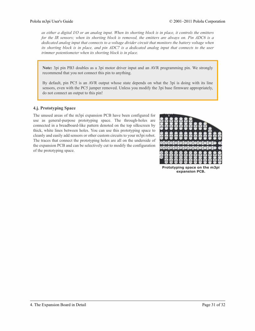
Prototyping space on the m3piexpansion PCB.
as either a digital I/O or an analog input. When its shorting block is in place, it controls the emittersfor the IR sensors; when its shorting block is removed, the emitters are always on. Pin ADC6 is adedicated analog input that connects to a voltage divider circuit that monitors the battery voltage whenits shorting block is in place, and pin ADC7 is a dedicated analog input that connects to the usertrimmer potentiometer when its shorting block is in place.
Note: 3pi pin PB3 doubles as a 3pi motor driver input and an AVR programming pin. We stronglyrecommend that you not connect this pin to anything.
By default, pin PC5 is an AVR output whose state depends on what the 3pi is doing with its linesensors, even with the PC5 jumper removed. Unless you modify the 3pi base firmware appropriately,do not connect an output to this pin!
4.j. Prototyping SpaceThe unused areas of the m3pi expansion PCB have been configured foruse as general-purpose prototyping space. The through-holes areconnected in a breadboard-like pattern denoted on the top silkscreen bythick, white lines between holes. You can use this prototyping space tocleanly and easily add sensors or other custom circuits to your m3pi robot.The traces that connect the prototyping holes are all on the underside ofthe expansion PCB and can be selectively cut to modify the configurationof the prototyping space.
Pololu m3pi User's Guide © 2001–2011 Pololu Corporation
4. The Expansion Board in Detail Page 31 of 32

4.k. m3pi Schematic Diagram
A larger version is available for download as a pdf: m3pi schematic [http://www.pololu.com/file/download/m3pi_schematic.pdf?file_id=0J499] (25k pdf).
Advanced users might also be interested in the 3pi schematic [http://www.pololu.com/file/download/3pi_schematic.pdf?file_id=0J119] (40k pdf).
Pololu m3pi User's Guide © 2001–2011 Pololu Corporation
4. The Expansion Board in Detail Page 32 of 32