polymer-made robot mechanisms and their applications · polymer-made robot mechanisms and their...
TRANSCRIPT

The 14th IFToMM World Congress, Taipei, Taiwan, October 25-30, 2015 DOI Number: 10.6567/IFToMM.14TH.WC.OS10.004
Polymer-made Robot Mechanisms and their Applications
Mikio Horie1
Tokyo Institute of Technology
Yokohama, Japan
Abstract: This paper is described about the polymer robot
mechanisms, for examples, a 2DOF(degrees-of-freedom)
pantograph mechanism and a 3DOF planar parallel
mechanism for new surface mount system in one room
factory. First, the displacement characteristics, the
relationship between frequency and positioning accuracy,
etc. are discussed about a polymer-made 2DOF pantograph
mechanism, and its application is shown. Second, the
dynamic displacement of output link, the result of the impact
test, etc. are discussed in experiments about a polymer-
made 3DOF planar parallel mechanism, and its application
is shown, where in this study, 2DOF XY direction motion is
discussed. In the results, the displacement characteristics
of polymer-made robot mechanisms proposed in this
research became clear. Keywords: Polymer-made 2DOF pantograph mechanisms, Polymer-
made 3DOF planar parallel mechanisms, Large-deflective hinges
I. Introduction
Recently, the use of cellular phones has become
prevalent worldwide. It is expected that the number of
cellular phone subscribers will reach 4 billion more and the
number of cellular phones shipped will reach more than 1
billion more by 2010 or later. Surface mount technology
related to the production of mobile products, such as the
electronic parts mounted on a cellular phone, are numbered
from several hundred to approximately a thousand. There is
a great number of a various parts mounted on the surface of
a printed circuit board. In order to effectively encourage
downsizing as well as increase the production rate of
installation machinery, a new miniature placement system
has been proposed by Horie [1] ~ [3]. Moreover, many
researches are done about optimization of a mounting
procedure, and there is also an example which applies to an
actual mounting line and is achieving success[4],[5].
The above system proposed by Horie is divided into two
groups. One group is the miniature manipulator that picks
up electronic devices, and then mounts them on a printed-
circuit- board. The other group is the positioning
mechanism that carries printed-circuit-board between
assembling-process stations, and its mechanism has a
positioning function at a station. The pantograph
mechanism and the positioning mechanism made of
polypropylene are used in the miniature manipulator and the
positioning table, respectively. The purpose of this study is
to experimentally produce a miniature surface-mount-
system that can be used for both downsizing the labor
necessary as well as speeding up the installation systems
followed by evaluation.
II. Proposal for a Miniature Surface Mount System
using an Injection Molding Pantograph Mechanism
A. Pantograph mechanisms and their application
The strategy of the 2DOF pantograph mechanism used in
this system is that the input displacement (SY, SZ) is
magnified minus 4-times in Y direction and plus 5-times in
Z direction, and the link and hinge pieces are combined and
molded by an injection molding. The injection-molding
pantograph mechanism is lightweight and is characterized
by an ease of mass-production as well as a rapid assembly
time.
As shown in Fig. 1, this study proposes a system
consisting of a group of miniature manipulators using an
injection-molding pantograph mechanism and a 2DOF XY
table. The printed circuit boards to be carried are presumed
to be a maximum of 100mm x 50mm. The width of a station,
which is an operating unit, is presumed to be 100mm. The
manipulators, which perform pick-and-place operation, go
and return on a path(50mm*20 mm) between a point on a
printed circuit board and a feeder. The manipulators can
handle anything from microchip parts to odd-shaped parts,
and in principle, one manipulator handles one kind of part.
This study presents a surface mount system with multiple
XY tables which move independently along the same rail.
The XY tables have 2DOF in the X and Y directions, and
one XY table carries one substrate.
This study will also decide the mounting procedures to
evaluate the mounting efficiency. Unique mounting
procedures are necessary because it is conditional that the
mounting parts should be timed nicely between the front
and rear substrates on the rail, and that fixed manipulators
perform pick-and-place operation independently in this
system.
First, an equation is formulated to evaluate the mounting
system. When one manipulator mounts only one part on one
substrate at one time, the number of stations (NS) becomes
N1NM, and the length of the mounting line (L) can be
derived by the equation L=NS(WS+WD), where, WS and WD
means the length of a station and the distance between
manipulators in a station, respectively.
When time, which is required for the operation at a
station and moving to the next station (TS), is the same as
between all of the stations, individual substrate moves
without delay. Therefore, cycle time (CT) expressed by
CT=NSTS and throughput of the system can be improved by
reducing TS. At this time, the number of parts mounted on
the whole system per unit time can be expressed by
EC=N/TS, where, N means the number of parts mounted on a
substrate.
TS becomes the smallest if the conditions are met, such
as (1) XY tables do not wait for the operation of

manipulators, (2) The movement of XY tables in the X
direction does not wait for the movement in the Y direction,
and (3) The movement of XY table in the X direction is
only in the positive direction. Therefore, it is necessary to
establish a mounting system to meet the conditions. The
equation necessary to express these conditions are
determined by the Equations. And, finally, TS, that is, time
required for the operation at a station and moving to the
next station, is expressed by the equation:
Next, the method for the mounting procedures is decided.
Afterward, the following method will be used as the unified
method to evaluate the mounting efficiency.
The system is divided into ten in the X-direction, and
mounting is started from the lower left toward the X-
direction. When mounting reaches the right end, it loops
back to the minus X-direction. When it reaches the left end,
it loops back again toward the X direction, proceeding on
toward the upper end.
Finally, the mounting efficiency was simulated when
conditions of the system and the number of the parts were
assumed.
The mounting efficiency determined by the following
methods is listed in Table 1.
1. The target positions of parts given by random number
are sorted by the method mentioned above.
2. Conditions are substituted into the TS equation to
determine TS.
3. When the results do not match the conditions, max
latency will be added to TS.
4. Mounting efficiency is determined by TS and
conditions.
5. The mean value of mounting efficiency is determined
after repeating the simulation ten times.
From the results of Table 1, the values of mounting takt
time were over several hundred thousand CPH (chip per
hour), which is just as good or better efficiency as the actual
use of a mounting machine.
Table 1. Computational results of efficiency [ UNIT: cph(chip per hour) ]
10 30 50 10 30 50 10 30 503 41087 44565 44565 66007 84309 85919 95339 140296 154242 32405 46790 46790 46790 79893 90045 90045 111180 162749 169014 18807 34007 34649 34649 54828 64935 64935 78261 108434 115311 14003 112254 132548 133185 171429 233312 248447 230769 365854 412371 64405 101152 101666 101666 163043 189873 189873 221402 320856 335508 38807 90407 96904 96904 138143 168776 168776 186239 254237 254237 28133 652884 769889 769889 965665 1366743 1446945 1269394 2068966 2365309 332405 641483 740436 740436 1025641 1298701 1388889 1408451 2080925 2275601 198807 539245 645161 680015 797519 1054482 1127113 1047730 1640839 1704545 14226
NM
VX mm/s
L mm
100 200 400Vy mm/s Vy mm/s Vy mm/s
50
100
500
N
Fig. 1. An example of placement machines line using
pantograph mechanisms
Fig. 3. A pantograph mechanism moved by DC solenoids Fig. 2. A fabricated pantograph mechanism with large-deflective hinge

B. Experimental Production of Miniature Surface mount
System
The manipulators for the miniature surface mount system
proposed in this study consist of injection-molding
pantograph mechanisms shown in Fig. 2, DC solenoids
driving manipulators shown in Fig. 3, and vacuum tweezers,
to absorb and detach minute parts. The DC solenoid is
moderate in price and rapid in operation.
Moreover, because the manipulators are used only at the
both ends of a certain stroke, the use of DC solenoid is
considered to be appropriate for driving miniature
manipulators.
With the stroke of the DC solenoid being magnified by
the pantograph, the tip of pantograph can move within an
intended work area, 50mm x 20mm. The tip of the
pantograph advances or climbs upward using a magnetic
force when the solenoid is energized, and then steps retreats
or is lowered with a return spring. The solenoid is controlled
by on-off signals from a PC. In order to know the response
time of solenoid, the current waveform of when the
injection-molding pantograph mechanism was mounted and
activated was measured, and as a result, it was found that
the time length from switch-on to the completion of iron
core movement in Y direction was 0.05s. It was also found
that the time was 0.06s in Z direction as shown in Fig. 4,
from which it is known that the pulse voltage applied to
solenoid is 10 Hz at the highest.
Figure 5 shows the graphs which illustrate the repeated
positioning accuracy for placement by performing pick and
place operation while changing frequency. From the graphs,
it is revealed that errors are becoming greater near where the
frequency exceeds 1.5 Hz. Approximately 100% of
placement operations and pick-up operations were
performed successfully during 50 µs for the chips with the
size from 0603(0.6[mm]×0.3[mm])to 3216 (3.2[mm]
×1.6[mm] ).
Fig. 6. Picture of 2 DOF XY table
Fig. 7. Relationship between a moving displacement
and maximum error
Displacement L mm E
rro
r Δ
L
m
T a r g e t
: X direction
: Y direction
50
40
30
20
10
0 50 100 150 200
Fig. 5. Relationship between frequency
and positioning accuracy
Maxim
um
erro
r m
m
Y direction error
of end-effector
Frequency Hz
0 0.5 1 1.5 2 2.5 3
0.6
0.5
0.3
0.2
0.2
0.1
Maxim
um
erro
r m
m
X direction error
of end-effector
0.6
0.5
0.3
0.2
0.2
0.1
0 0.5 1 1.5 2 2.5 3
Frequency Hz
Fig. 4. Vibration of output point of manipulator
1.5
-0.6
-0.4
-0.2
0
0.4
0.6
-0.5 0.5 1
0.2
Time s
Y
1.5
-0.6
-0.4
-0.2
0
0.4
0.6
-0.5 0.5 1
0.2
Time s
Y
-0.6
-0.4
-0.2
0
0.2
0.4
0.6
-0.5 0.5 1 1.5
Time s
X
-0.6
-0.4
-0.2
0
0.2
0.4
0.6
-0.5 0.5 1 1.5
Time s
X
-0.6
-0.4
-0.2
0
0.2
0.4
0.6
-0.5 0.5 1 1.5
Time s
Z
-0.6
-0.4
-0.2
0
0.2
0.4
0.6
-0.5 0.5 1 1.5
Time s
Z

C. Experimental Production of 2DOF XY Table
Rack pinion mechanisms have been applied because
numerous XY tables carrying print circuit boards are placed
on the same rail in X direction. Ball screw mechanisms are
applied on the X-direction actuators in Y direction for the
purpose of accuracy. Each actuator uses a DC coreless
motor.
Analog positioning control, which is superior in fast
response, is applied for the control of 2DOF XY tables, for
which a positioning instruction value is input through a PC.
The signal output from an encoder equipped in the motor is
fed back, compared with the positioning instruction value
through the PC. The PI control performed by an
integrating circuit and a derivative circuit. The PWM circuit
is used for the amplification of input voltage to motors. The
manufactured 2DOF XY table is shown in Fig. 6
Responses to the step input for an approximately
60mm moving distance in X direction and an approximately
4.5 mm moving distance in Y direction of the 2DOF XY
tables experimentally produced were measured by an
encoder. As a result, because the power supply voltage was
12V at the maximum, a linear rise is shown, from which the
maximum velocity to each direction of the 2DOF XY table
can be known. The maximum velocity in X direction is
approximately 190 mm/s and in Y direction approximately
30 mm/s.
Then, the accuracy of positioning was measured by an
experiment. For the measurement of arrival positions, a
displacement sensor was set near the target value and
measured the distance between the displacement sensor and the target. Figure 7 is a graph demonstrating the relationship between moving distances and errors for the measurement of positioning accuracy. From this graph it can be seen that the positioning accuracy is approximately 50 µm in X direction and approximately 10 µm in Y direction. As a result of repeated measuring of the positioning accuracy by changing moving velocity, it can be seen that it was approximately ± 15 µm in the X direction and approximately ± 5 µm in the Y direction with a velocity range between 0~10 mm/s as shown in Fig. 8.
D. Experiment and Evaluation of the Operation of
Miniature Surface mount System Figure 9 shows experimentally produced experimental equipment consisting of a station with three surface mount systems and a 2DOF XY table. The control system of the entire equipment is shown in Fig. 10. All control is performed in accordance with the sequence control using input signals sent through a PC. The performance of the surface mount system proposed in this study is evaluated by the experimental results obtained so far. The placement efficiency calculated using parameters obtained thus far for the purpose of evaluation of the miniature surface mount system included the experimentally produced experimental equipment shows that the placement tact time is 63989 cph when the number of products is 50, 166821 cph when it is 100, and 941423 cph when it is 500.
Fig. 8. Relationship between velocity of actuator and max. positioning accuracy repeatability
[(a) X direction, (b) Y direction]
(b)
Po
siti
on
acc
ura
cy
rep
eata
bil
ity
m
Velocity of actuator mm/s
8
6
4
2
0 5 10 15
(a)
Po
siti
on
acc
ura
cy
rep
eata
bil
ity
m
Velocity of actuator mm/s
0 50 100 150 200
30
25
20
15
10
5
Fig. 10. Control systems of surface mount system
Fig. 9. Picture of surface mount system
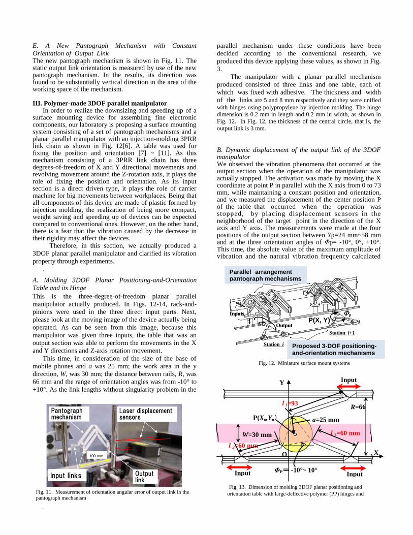
E. A New Pantograph Mechanism with Constant
Orientation of Output Link The new pantograph mechanism is shown in Fig. 11. The static output link orientation is measured by use of the new pantograph mechanism. In the results, its direction was found to be substantially vertical direction in the area of the working space of the mechanism.
III. Polymer-made 3DOF parallel manipulatorIn order to realize the downsizing and speeding up of a
surface mounting device for assembling fine electronic components, our laboratory is proposing a surface mounting system consisting of a set of pantograph mechanisms and a planar parallel manipulator with an injection-molding 3PRR link chain as shown in Fig. 12[6]. A table was used for fixing the position and orientation [7] ~ [11]. As this mechanism consisting of a 3PRR link chain has three degrees-of-freedom of X and Y directional movements and revolving movement around the Z-rotation axis, it plays the role of fixing the position and orientation. As its input section is a direct driven type, it plays the role of carrier machine for big movements between workplaces. Being that all components of this device are made of plastic formed by injection molding, the realization of being more compact, weight saving and speeding up of devices can be expected compared to conventional ones. However, on the other hand, there is a fear that the vibration caused by the decrease in their rigidity may affect the devices.
Therefore, in this section, we actually produced a
3DOF planar parallel manipulator and clarified its vibration
property through experiments.
.
A. Molding 3DOF Planar Positioning-and-Orientation
Table and its Hinge
This is the three-degree-of-freedom planar parallel
manipulator actually produced. In Figs. 12-14, rack-and-
pinions were used in the three direct input parts. Next,
please look at the moving image of the device actually being
operated. As can be seen from this image, because this
manipulator was given three inputs, the table that was an
output section was able to perform the movements in the X
and Y directions and Z-axis rotation movement.
This time, in consideration of the size of the base of
mobile phones and a was 25 mm; the work area in the y
direction, W, was 30 mm; the distance between rails, R, was
66 mm and the range of orientation angles was from -10° to
+10°. As the link lengths without singularity problem in the
parallel mechanism under these conditions have been
parallel mechanism under these conditions have been
decided according to the conventional research, we
produced this device applying these values, as shown in Fig.
3.
The manipulator with a planar parallel mechanism
produced consisted of three links and one table, each of
which was fixed with adhesive. The thickness and width
of the links are 5 and 8 mm respectively and they were unified
with hinges using polypropylene by injection molding. The hinge
dimension is 0.2 mm in length and 0.2 mm in width, as shown in
Fig. 12. In Fig. 12, the thickness of the central circle, that is, the
output link is 3 mm.
B. Dynamic displacement of the output link of the 3DOF manipulator We observed the vibration phenomena that occurred at the output section when the operation of the manipulator was actually stopped. The activation was made by moving the X coordinate at point P in parallel with the X axis from 0 to 73 mm, while maintaining a constant position and orientation, and we measured the displacement of the center position P of the table that occurred when the operation was stopped, by placing displacement sensors in the neighborhood of the target point in the direction of the X axis and Y axis. The measurements were made at the four positions of the output section between Yp=24 mm~58 mm and at the three orientation angles of Φp= -10°, 0°, +10°. This time, the absolute value of the maximum amplitude of vibration and the natural vibration frequency calculated
Input links
Pantographmechanism
Laser displacement sensors
Outputlink
100 mm
Fig. 12. Miniature surface mount systems
Station i
Inputs
Output
Pantograph mechanisms
3-DOF parallel mechanisms
Station i+1
Station i
Inputs
Output
Pantograph mechanisms
3-DOF parallel mechanisms
Station i+1
p P(X, Y)
Proposed 3-DOF positioning- and-orientation mechanisms
Parallel arrangement pantograph mechanisms
Fig. 11. Measurement of orientation angular error of output link in the pantograph mechanism
Fig. 13. Dimension of molding 3DOF planar positioning and
orientation table with large-deflective polymer (PP) hinges and
links
l 2=60 mm X
Y
O
P(Xp,Yp
)
ΦP= -10°~ 10°
W=30 mm
a=25 mm
R=66
mm
Input Input
l 1=93
mm
l 3=60 mm
Input
)
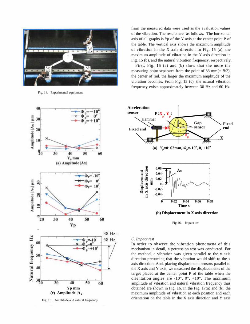
from the measured data were used as the evaluation values
of the vibration. The results are as follows. The horizontal
axis of all graphs is Yp of the Y axis at the center point P of
the table. The vertical axis shows the maximum amplitude
of vibration in the X axis direction in Fig. 15 (a), the
maximum amplitude of vibration in the Y axis direction in
Fig. 15 (b), and the natural vibration frequency, respectively.
First, Fig. 15 (a) and (b) show that the more the
measuring point separates from the point of 33 mm(= R/2),
the center of rail, the larger the maximum amplitude of the
vibration becomes. From Fig. 15 (c), the natural vibration
frequency exists approximately between 30 Hz and 60 Hz.
C. Impact test
In order to observe the vibration phenomena of this
mechanism in detail, a percussion test was conducted. For
the method, a vibration was given parallel to the x axis
direction presuming that the vibration would shift to the x
axis direction. And, placing displacement sensors parallel to
the X axis and Y axis, we measured the displacements of the
target placed at the center point P of the table when the
orientation angles are -10°, 0°, +10°. The maximum
amplitude of vibration and natural vibration frequency thus
obtained are shown in Fig. 16. In the Fig. 17(a) and (b), the
maximum amplitude of vibration at each position and each
orientation on the table in the X axis direction and Y axis
Fig. 14. Experimental equipment
Yp mm
(c) Amplitude |AY|
Fig. 15. Amplitude and natural frequency
Fig.16. Impact test
0 0.02 0.04 0.06 0.08
-0.04
-0.02
0
0.02
0.04
0.06
Dis
pla
cem
en
t
in X
ax
is d
irec
tio
n
mm
Time s
AX
P(Xp, Y
p)
Acceleration
sensor
Fixed end
X
Gap sensor
Fixed end
(a) Yp=0~62mm, Φp=-10o, 0, +10
o
φP
(b) Displacement in X axis direction
Hammer
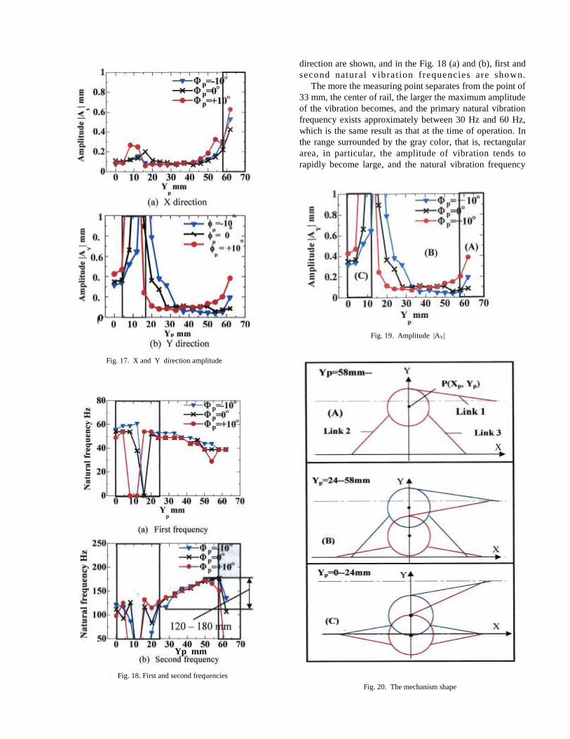
direction are shown, and in the Fig. 18 (a) and (b), first and
second natural vibrat ion frequencies are shown.
The more the measuring point separates from the point of
33 mm, the center of rail, the larger the maximum amplitude
of the vibration becomes, and the primary natural vibration
frequency exists approximately between 30 Hz and 60 Hz,
which is the same result as that at the time of operation. In
the range surrounded by the gray color, that is, rectangular
area, in particular, the amplitude of vibration tends to
rapidly become large, and the natural vibration frequency
Fig. 19. Amplitude |AY|
Fig. 17. X and Y direction amplitude
Fig. 18. First and second frequencies
Yp mm
X
Fig. 20. The mechanism shape
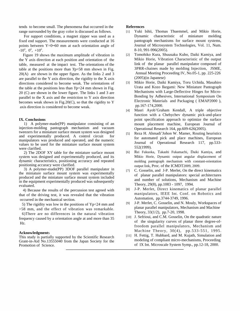
tends to become small. The phenomena that occurred in the
range surrounded by the gray color is discussed as follows.
For support conditions, a magnet zipper was used as a
fixed end support. The measurements were conducted at 16
points between Y=0~60 mm at each orientation angle of
-10o, 0
o, +10
o.
Figure 19 shows the maximum amplitude of vibration in
the Y axis direction at each position and orientation of the
table, measured at the impact test. The orientations of the
table at the positions more than Yp=58 mm shown in Fig.
20(A) are shown in the upper figure. As the links 2 and 3
are parallel to the Y axis direction, the rigidity to the X axis
directions considered to become weak. The orientations of
the table at the positions less than Yp=24 mm shown in Fig.
20 (C) are shown in the lower figure. The links 1 and 3 are
parallel to the X axis and the restriction to Y axis direction
becomes weak shown in Fig.20(C), so that the rigidity to Y
axis direction is considered to become weak.
IX. Conclusions1) A polymer-made(PP) manipulator consisting of an
injection-molding pantograph mechanism and vacuum tweezers for a miniature surface mount system was designed and experimentally produced. A control circuit for manipulators was produced and operated, and the numeric values to be used for the miniature surface mount system were clarified.
2) The 2DOF XY table for the miniature surface mountsystem was designed and experimentally produced, and its dynamic characteristics, positioning accuracy and repeated positioning accuracy were clarified.
3) A polymer-made(PP) 3DOF parallel manipulator inthe miniature surface mount system was experimentally produced and the miniature surface mount system included in the equipment experimentally produced was subsequently evaluated.
4) Because the results of the percussion test agreed with
that of the driving test, it was revealed that the vibration
occurred in the mechanical section.
5) The rigidity was low in the positions of Yp<24 mm and
>58 mm, and the effect of vibration was remarkable.
6)There are no differences in the natural vibration
frequency caused by a orientation angle at and more than 35
Hz.
Acknowledgments This study is partially supported by the Scientific Research Grant-in-Aid No.13555040 from the Japan Society for the Promotion of Science.
References
[1] Yuki Ishii, Thomas Thuemmel, and Mikio Horie,
Dynamic characteristic of miniature molding
pantograph mechanisms for surface mount systems,
Journal of Microsystem Technologies, Vol. 11, Num.
8-10, 991-996(2005).
[2] Tomohiko Kura, Shuusaku Kubo, Daiki Kamiya, and
Mikio Horie, Vibration Characteristic of the output
link of the planar parallel manipulator composed of
3PRR-chaines made by molding Injection, JSME,
Annual Meeting Proceeding IV, No.05-1, pp. 225-226
(2005)(in Japanese)
[3] Mikio Horie, Daiki Kamiya, Toru Uchida, Masahiro
Urata and Kozo Ikegami: New Miniature Pantograph
Mechanisms with Large-Deflective Hinges for Micro-
Bonding by Adhesives, International Symposium On
Electronic Materials and Packaging ( EMAP2000 ),
pp.167-174,2000.
[4] Masri Ayob’Graham Kendall, A triple objective
function with a Chebychev dynamic pick-and-place
point specification approach to optimize the surface
mount placement machine, European Journal of
Operational Research 164, pp.609-626(2005).
[5] Reza H. Ahmadi’Johon W. Mamer, Routing heuristics
for automated pick and place machines, European
Journal of Operational Research 117, pp.533-
552(1999).
[6] Rei Fukuoka, Takashi Fukamachi, Daiki Kamiya, and
Mikio Horie, Dynamic output angular displacement of
molding pantograph mechanism with constant-orientation
output link, Proc. of the ICMDT2009, 2009.
[7] C. Gosselin, and J-P. Merlet, On the direct kinematics
of planar parallel manipulators: special architectures
and number of solutions, Mechanism and Machine
Theory, 29(8), pp.1083 - 1097, 1994.
[8] J-P. Merlet, Direct kinematics of planar parallel
manipulators, IEEE Int. Conf. on Robotics and
Automation, pp.3744-3749, 1996.
[9] J-P. Merlet, C. Gosselin, and N. Mouly, Workspaces of
planar parallel manipulators, Mechanism and Machine
Theory, 33(1/2), pp.7-20, 1998.
[10] J. Sefrioui, and C.M. Gosselin, On the quadratic nature
of the singularity curves of planar three degree-of-
freedom parallel manipulators, Mechanism and
Machine Theory, 30(4) , pp.533-551, 1995.
[11] H. Fettig, T. Hubbard, and M. Kujath, Simulation and
modeling of compliant micro-mechanisms, Proceeding
of IX Int. Microscale System Symp., pp.12-18, 2000.