polymesher: a general-purpose mesh generator for …polymesher: a general-purpose mesh generator for...
TRANSCRIPT

PolyMesher: A General-Purpose Mesh
Generator for Polygonal Elements
Written in Matlab
Anderson Pereira, Cameron Talischi, Ivan F. M. Menezes and Glaucio H. Paulino

Motivation
• Voronoi diagrams offer a simple way to discretize geometries. They have
been widely used to describe the material structure in:
2

Motivation
• Voronoi diagrams offer a simple way to discretize geometries. They have
been widely used to describe the material structure in:
– polycrystalline microstructures,
3
PR Bueno and JA Varela. Electronic ceramics
based on polycrystalline SnO2, TiO2 and (Sn
xTi1-x)O2 solid solution. Mat. Res. [online].
2006, vol.9, n.3, pp. 293-300
Motivation
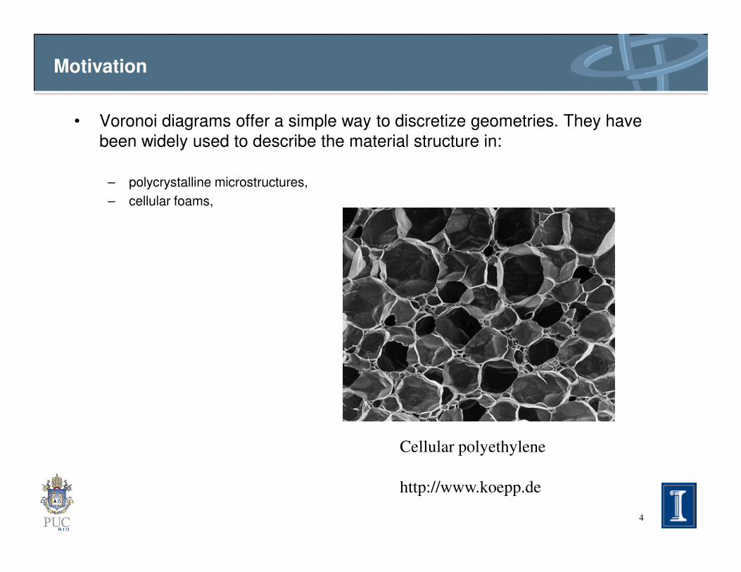
• Voronoi diagrams offer a simple way to discretize geometries. They have
been widely used to describe the material structure in:
– polycrystalline microstructures,
– cellular foams,
4
Cellular polyethylene
http://www.koepp.de

Motivation
• Voronoi diagrams offer a simple way to discretize geometries. They have
been widely used to describe the material structure in:
– polycrystalline microstructures,
– cellular foams,
– and other materials that exhibit cell-like features.
• For such applications, numerical modeling and simulation of Voronoi
meshes is a natural choice.
5
meshes is a natural choice.
• Finite element analyses can also be based on the Delaunay/Voronoi dual
tessellations for both defining the computational mesh and approximating
the field quantity within each element.

Motivation
• Recently, polygonal meshes were used in topology optimization yielding good
results.
Polygonal Elements T6 Elements
6
C. Talischi, G. Paulino, A. Pereira and IFM Menezes. Polygonal finite elements for topology
optimization: A unifying paradigm. IJNME, 82(6):671-698, 2010

Motivation
• Recently, polygonal meshes were used in topology optimization yielding good
results.
7
C. Talischi, G. Paulino, A. Pereira and IFM Menezes. Polygonal finite elements for topology
optimization: A unifying paradigm. IJNME, 82(6):671-698, 2010
18 dofs – %51 error
20 dofs – %27 error
3 quads and 1 pentagon
Motivation
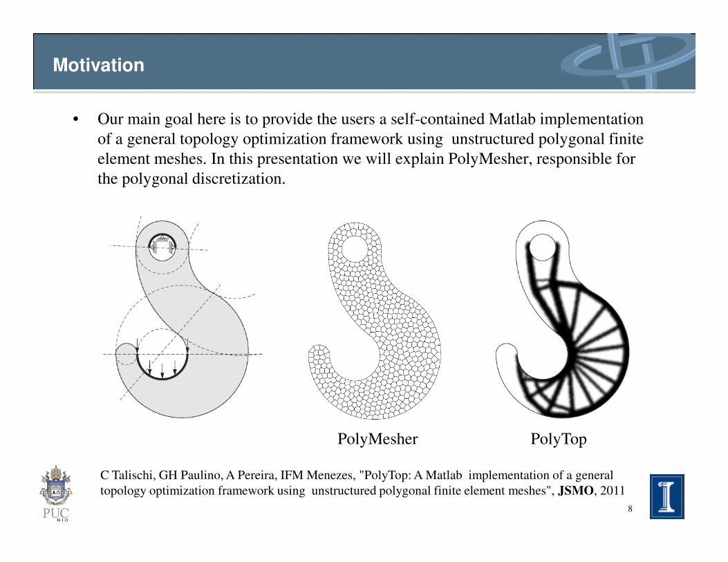
• Our main goal here is to provide the users a self-contained Matlab implementation
of a general topology optimization framework using unstructured polygonal finite
element meshes. In this presentation we will explain PolyMesher, responsible for
the polygonal discretization.
8
C Talischi, GH Paulino, A Pereira, IFM Menezes, "PolyTop: A Matlab implementation of a general
topology optimization framework using unstructured polygonal finite element meshes", JSMO, 2011
PolyMesher PolyTop

Outline
• Voronoi diagrams, CVTs and Lloyd’s algorithm
• Meshing algorithm
• Implicit representation
• Matlab implementation
9
• Matlab implementation
• Examples
• Concluding remarks
• Ongoing work
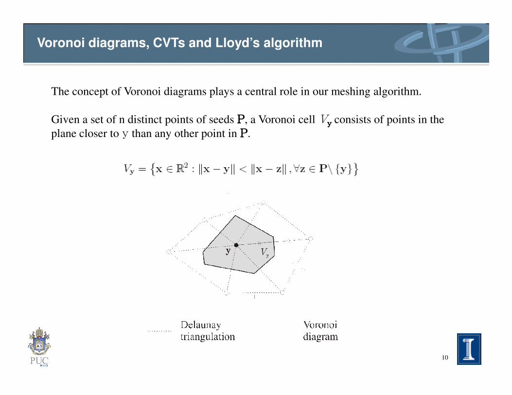
The concept of Voronoi diagrams plays a central role in our meshing algorithm.
Given a set of n distinct points of seeds PPPP, a Voronoi cell Vyyyy
consists of points in the
plane closer to y than any other point in PPPP.
Voronoi diagrams, CVTs and Lloyd’s algorithm
10
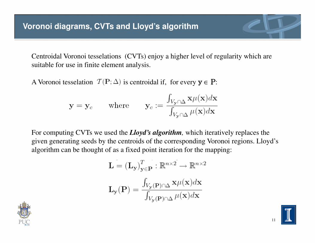
Centroidal Voronoi tesselations (CVTs) enjoy a higher level of regularity which are
suitable for use in finite element analysis.
A Voronoi tesselation is centroidal if, for every yyyy ∈ PPPP:
Voronoi diagrams, CVTs and Lloyd’s algorithm
11
For computing CVTs we used the Lloyd’s algorithm, which iteratively replaces the
given generating seeds by the centroids of the corresponding Voronoi regions. Lloyd’s
algorithm can be thought of as a fixed point iteration for the mapping:

Initial Random points First iteration After 80 iterations
Voronoi diagrams, CVTs and Lloyd’s algorithm
12
Initial Random points First iteration After 80 iterations

Voronoi diagrams, CVTs and Lloyd’s algorithm
13
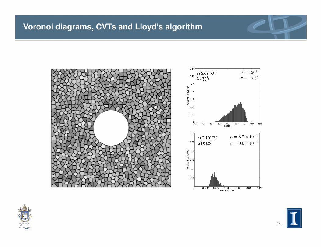
Voronoi diagrams, CVTs and Lloyd’s algorithm
14

Voronoi diagrams, CVTs and Lloyd’s algorithm
15
Meshing approach: basic ideas
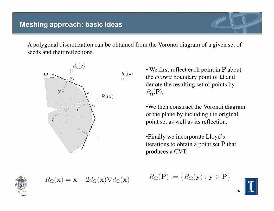
A polygonal discretization can be obtained from the Voronoi diagram of a given set of
seeds and their reflections.
• We first reflect each point in PPPP about
the closest boundary point of Ω and
denote the resulting set of points by
RΩ(PPPP).
•We then construct the Voronoi diagram
16
•We then construct the Voronoi diagram
of the plane by including the original
point set as well as its reflection.
•Finally we incorporate Lloyd’s
iterations to obtain a point set PPPP that
produces a CVT.

Implicit representation
One of the main ingredients of our mesh generator is the implicit representation of the
domain:
17
The signed distance function contains all the essential information about the meshing
domain needed in our mesh algorithm.
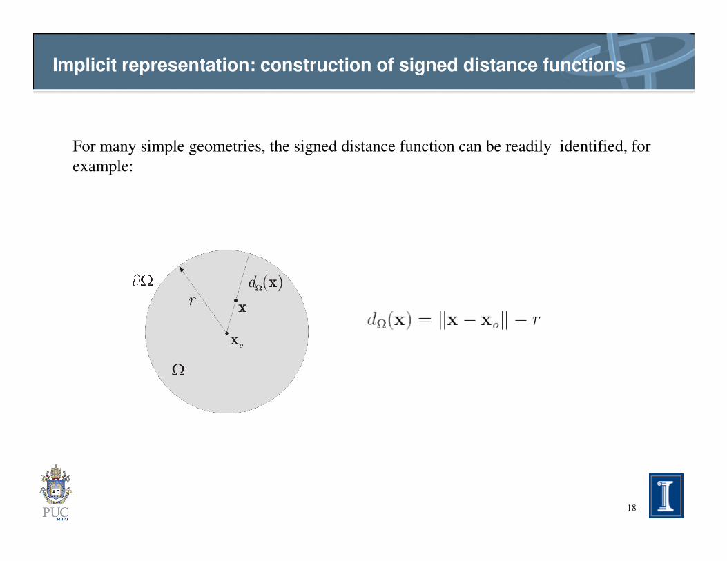
Implicit representation: construction of signed distance functions
For many simple geometries, the signed distance function can be readily identified, for
example:
18
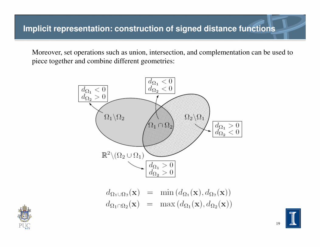
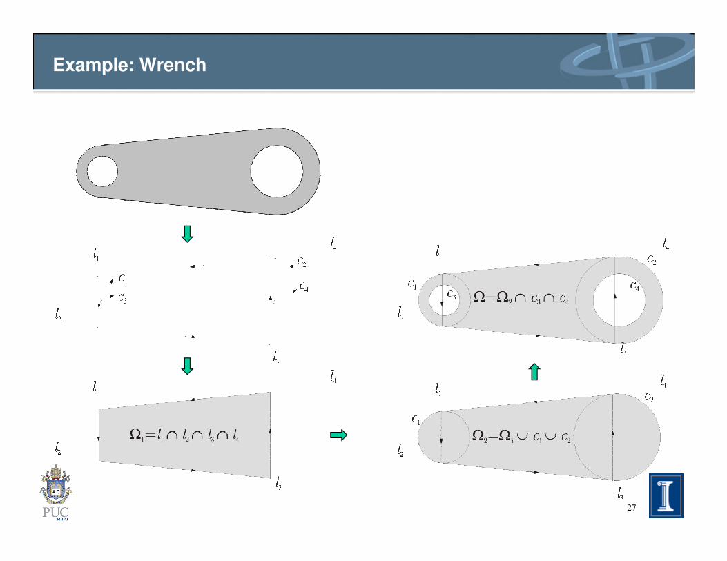
Implicit representation: construction of signed distance functions
Moreover, set operations such as union, intersection, and complementation can be used to
piece together and combine different geometries:
19
Matlab implementation
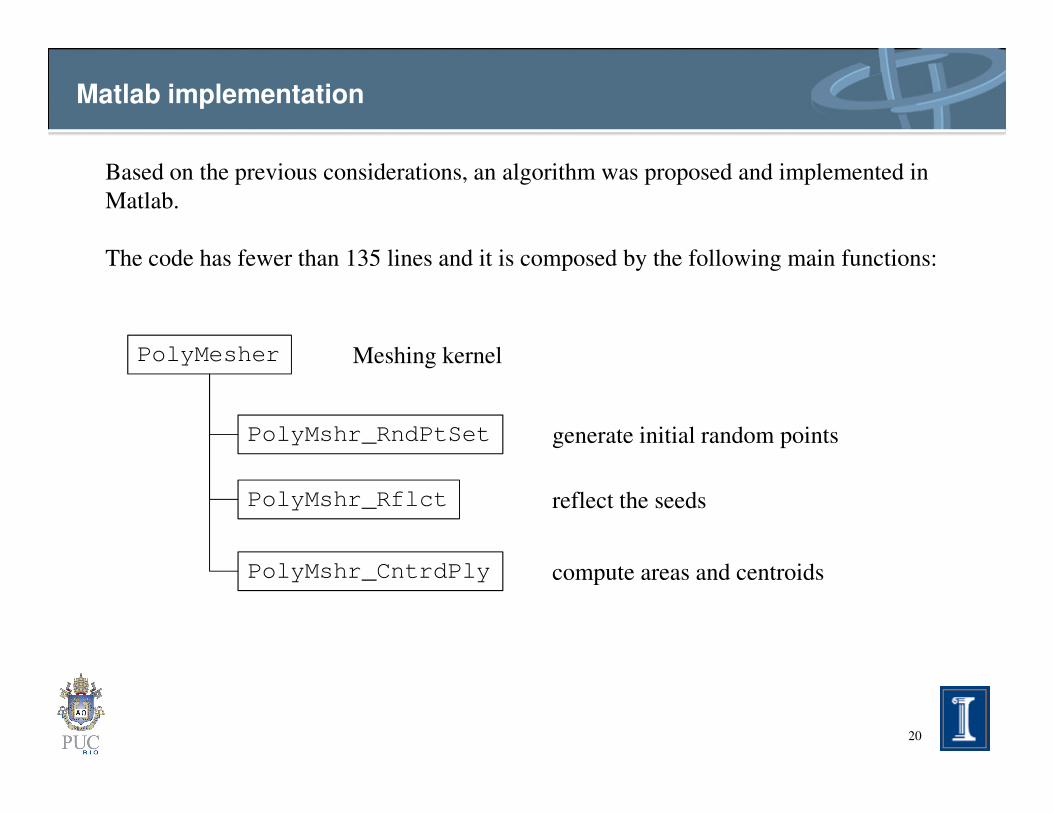
Based on the previous considerations, an algorithm was proposed and implemented in
Matlab.
The code has fewer than 135 lines and it is composed by the following main functions:
PolyMesher Meshing kernel
20
PolyMshr_RndPtSet generate initial random points
PolyMshr_Rflct reflect the seeds
PolyMshr_CntrdPly compute areas and centroids
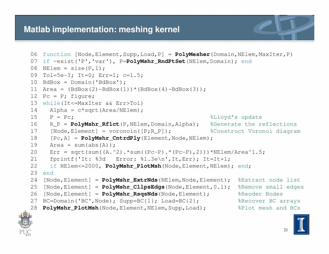
Matlab implementation: meshing kernel
function [Node,Element,Supp,Load,P] = PolyMesher(Domain,NElem,MaxIter,P)
if ~exist('P','var'), P=PolyMshr_RndPtSet(NElem,Domain); end
NElem = size(P,1);
Tol=5e-3; It=0; Err=1; c=1.5;
BdBox = Domain('BdBox');
Area = (BdBox(2)-BdBox(1))*(BdBox(4)-BdBox(3));
Pc = P; figure;
while(It<=MaxIter && Err>Tol)
Alpha = c*sqrt(Area/NElem);
P = Pc; %Lloyd's update
R_P = PolyMshr_Rflct(P,NElem,Domain,Alpha); %Generate the reflections
06
07
08
09
10
11
12
13
14
15
16
21
R_P = PolyMshr_Rflct(P,NElem,Domain,Alpha); %Generate the reflections
[Node,Element] = voronoin([P;R_P]); %Construct Voronoi diagram
[Pc,A] = PolyMshr_CntrdPly(Element,Node,NElem);
Area = sum(abs(A));
Err = sqrt(sum((A.^2).*sum((Pc-P).*(Pc-P),2)))*NElem/Area^1.5;
fprintf('It: %3d Error: %1.3e\n',It,Err); It=It+1;
if NElem<=2000, PolyMshr_PlotMsh(Node,Element,NElem); end;
end
[Node,Element] = PolyMshr_ExtrNds(NElem,Node,Element); %Extract node list
[Node,Element] = PolyMshr_CllpsEdgs(Node,Element,0.1); %Remove small edges
[Node,Element] = PolyMshr_RsqsNds(Node,Element); %Reoder Nodes
BC=Domain('BC',Node); Supp=BC1; Load=BC2; %Recover BC arrays
PolyMshr_PlotMsh(Node,Element,NElem,Supp,Load); %Plot mesh and BCs
16
17
18
19
20
21
22
23
24
25
26
27
28
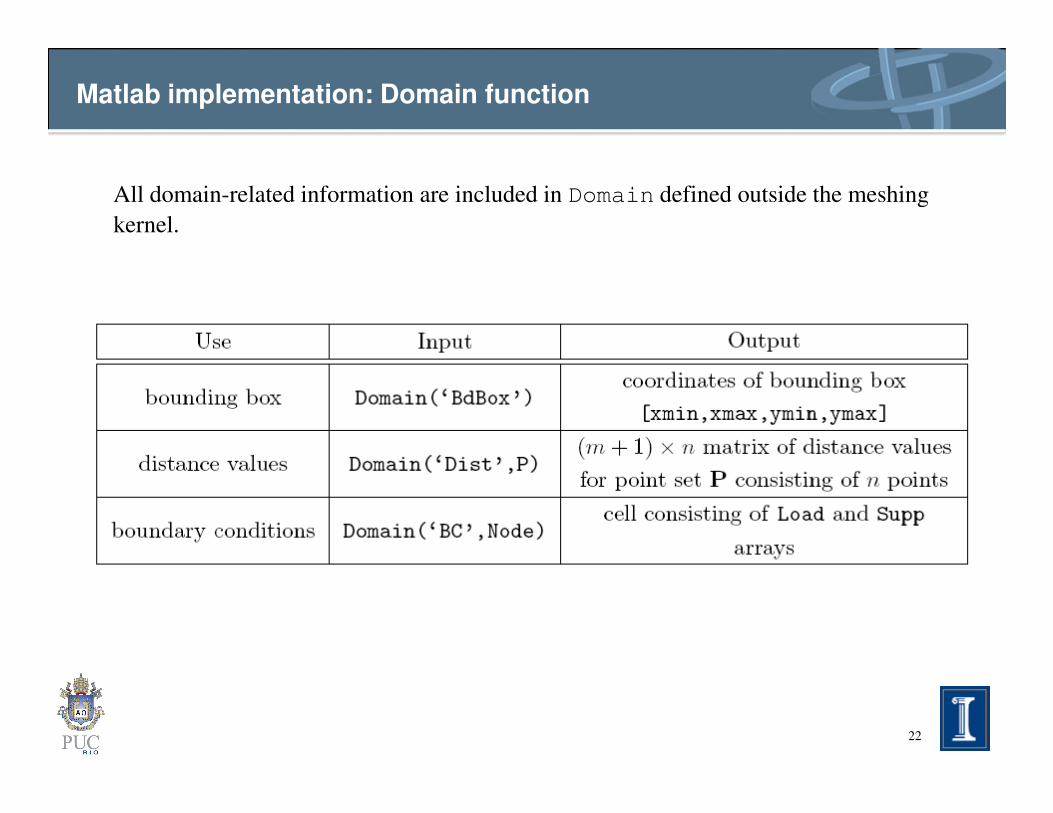
Matlab implementation: Domain function
All domain-related information are included in Domain defined outside the meshing
kernel.
22

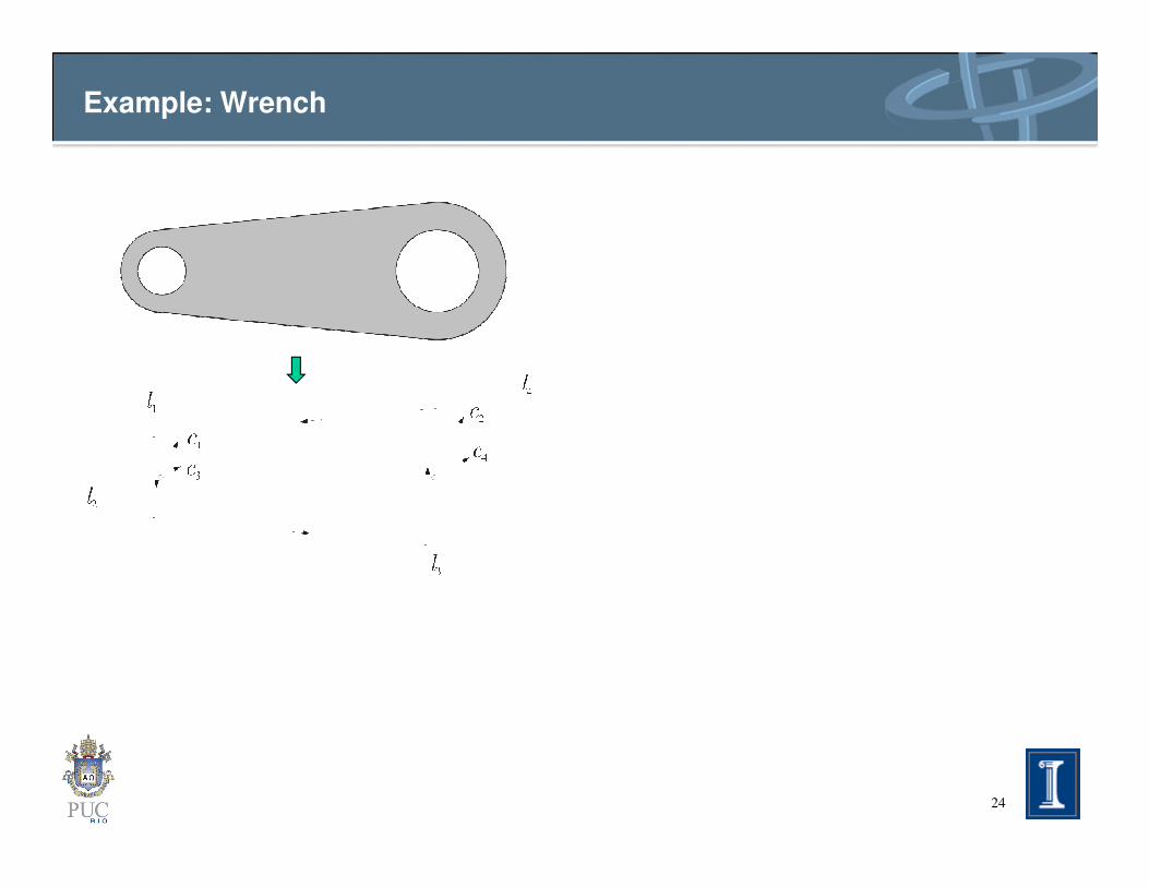
Example: Wrench
23
Example: Wrench
24

Example: Wrench
25

Example: Wrench
26
Example: Wrench
27

Example: Wrench
28

Examples
• Matlab demo
29

Example: symmetric Michell cantilever
30
P = [Pc(1:NElem/2,:);[Pc(1:NElem/2,1),-Pc(1:NElem/2,2)]];
function [Node,Element,Supp,Load,P] = PolyMesher(Domain,NElem,MaxIter,P)
...
while(It<=MaxIter && Err>Tol)
Alpha = c*sqrt(Area/NElem);
P = Pc; %Lloyd's update
R_P = PolyMshr_Rflct(P,NElem,Domain,Alpha); %Generate the reflections
[Node,Element] = voronoin([P;R_P]); %Construct Voronoi diagram
[Pc,A] = PolyMshr_CntrdPly(Element,Node,NElem);
...
end
6
...
13
14
15
16
17
18
...
23
15

Example: uniform discretizations
>> nelx = 30; nely = 10;
>> dx = 3/nelx; dy = 1/nely;
>> [X,Y] = meshgrid(dx/2:dx:3,dy/2:dy:1);
>> P = [X(:) Y(:)];
>> [Node,Element,Supp,Load] = PolyMesher(@MbbDomain,0,0,P);
31
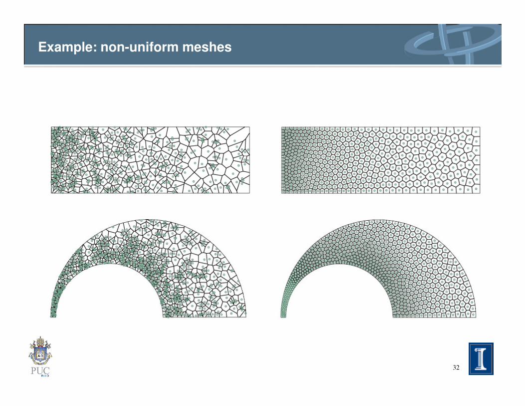
Example: non-uniform meshes
32
Concluding remarks
• Voronoi models arise in nature in various situations. In particular, polygonal meshes have been prominent in modeling structural problems;
• A simple and robust code based on the concept of Voronoi diagrams was presented. Using a simple and effective approach allows to
33
was presented. Using a simple and effective approach allows to discretize two-dimensional geometries with convex polygons;
• Its range of applications is broad, including optimization (shape, topology, etc), and other applications.
Acknowledgment
Tecgraf - Computer Graphics Technology
Group at the Pontifical Catholic University
of Rio de Janeiro - PUC-Rio - Brazil
34
Department of Energy Computational
Science Graduate Fellowship Program of
the Office of Science and National Nuclear
Security Administration in the Department
of Energy.