polyphase-discrete fourier transform spectrum analysis for ...polyphase-discrete fourier transform...
TRANSCRIPT

TDA ProgressReport42-107 November15, 1991
Polyphase-Discrete Fourier Transform Spectrum Analysis
for the Search for Extraterrestrial Intelligence
Sky SurveyG. A. Zimmerman
CommunicationsSystemsResearchSection
S. Gulkis
Space Physicsand AstrophysicsSection
The sensitivity of a matched filter-detection system to a finite-duration contin-
uous wave (CW) tone is compared with the sensitivities of a windowed discrete
Fourier transform (DFT) system and an ideal ba31dpass filter-bank system. Thesecomparisons are made in the context of the NASA Search for Extraterrestrial In-
telligence (SETI) microwave observing project (MOP) sky survey. A review ofthe theory of polyphase-DFT filter banks and its relationship to the well-known
windowed-DFT process is presented. The polyphase-DFT system approximates
the ideal bandpass filter bank by using as few as eight filter taps per polyphase
branch. An improvement in sensitivity of "-'3 dB over a windowed-DFT systemcan be obtained by using the polyphase-DFT approach. Sidelobe rejection of the
polyphase-DFT system is vastly superior to the windowed-DFT system, thereby
improving its performance in the presence of radio frequency interference (RFI).
I. Introduction
The Search for Extraterrestrial Intelligence (SETI) sky
survey will use a spectrum-analysis system with a
640-MHz totaI bandwidth and 33,554,432 (225) channelsdivided equally between two 320-Mliz-wide polariza-
tions Ill. The purpose of the system is to detect finite-
duration continuous wave (CW) tones. Cost and technol-ogy constrain the number of channels in the system. To
evaluate the resulting sensitivity loss, a study was under-
taken of the relative sensitivities of theoretically optimal
detection and systems with a fixed number of channels.
Spectrum analysis by means of a windowed discrete
Fourier transform (DFT), usually implemented as a fast
Fourier transform (FFT), is used in a wide variety of
fields [2]. For the SETI sky survey, as in many appli-
141
https://ntrs.nasa.gov/search.jsp?R=19920005033 2020-03-31T16:59:38+00:00Z

cations, a windowed DFT has been proposed to chan-
nelize the input bandwidth [3]. The windowed DFT
isolates interference in the frequency domain and allows
CW signal-detection algorithms to operate on the narrow-
band output channels of the DFT, which improves the
signal-to-noise ratio (SNR) at which signal detection musttake place. However, the superior sidelobe rejection of
windowed DFT's does not come without a performance
penalty. This penalty is well-known and is tabulated in [2]for various window functions. For most common window
functions, the worst-case processing loss is between 3 to4 dB. For the SETI sky survey, this loss would add to that
incurred by fixing the number of channels. Recovering this
processing loss would be equivalent to halving the hystem
temperature or doubling tile antenna's collecting area.
A multirate digital signal-processing technique, knownas a polyphase-DFT filter bank, is proposed to recover
most of the windowed-DFT processing loss while providingsuperior interference isolation. The theory of polyphase-DFT filter banks has been established in the multirate
digital-signal-processing community for some years now.
Itowever, unlike windowed-DFT techniques, the filter bank
theory is not, in general, well-known. It is the intent of
this article to propagate the theory of polyphase-DFT fil-ter banks as a technique related to tile use of windows
with DFT's, and it is suggested that applications using
Windowed DFT's might benefit by switching to polyphase-DFT filter banks.
The first part of this article compares the sensitivity of
the theoretically optimal matched filter-detection systemwith the sensitivities of a Hanning windowed-DFT system
and an ideal bandpass filter-bank system. The second part
reviews the theory of polyphase-DFT filter banks and their
relation to windowed DFT's. In the third part, the per-formance of simple polyphasc-DFT filter preprocessing isexamined.
!1. Comparative Sensitivities
The best possible sensitivity that can be expected with
the SETI sky survey will be achieved in the absence of ra-
dio frequency interference (RFI) with the use of a matched
filter detector [4]. It is therefore of interest to calculate the
matched filter-detection system sensitivity and use that as
a standard to judge how well tile SETI sky survey com-
pares with the optimum. The flux sensitivity that can
be achieved with a matched filter system is given in thissection. This sensitivity is also compared with two sys-
tems with the same fixed number of channels: a Hanning
windowed-DFT system of 30-tIz resolved equivalent noise
bandwidth and an ideal bandpass filter bank of 20-Hz re-solved bandwidth.
The SETI sky survey will sweep at a constant angular
rate on the sky with a DSN 34-m high-efficiency (HEF)
antenna. As the antenna transits a source on the sky,the source will be convolved by the antenna's beam shape.
For this analysis, the authors assume that the antenna
pattern sweeping past a CW point source can be approxi-
mated by a square-wave pulse of width equal to the half-
power beamwidth (ttPBW) of the antenna. The SNR fora matched filter system is then given by
SNR = ACtkT
where A is the effective area of the antenna, ¢ is the re-ceived flux, r is the approximate time to move the tele-
scope one HPBW, and kT is the spectral noise densityof the receiver and background. Most of these are sys-tem parameters. The authors assume a 34-m diameter
antenna with a 60-percent effective collecting area and a
system temperature of 25 K. The telescope is assumed to
be driven at a constant rate of 0.2 deg per second acrossthe sky. The constant scan rate gives a pulse duration, and
hence a resolved matched filter bandwidth, which varies
with frequency. The pulse duration time is approximately
r = 3/v sec, when v is expressed in GHz.
To determine the minimum detectable flux density, onemust first determine the minimum detectable SNR. Two
factors determine the SNR required for a detection by the
SETI sky survey. The first is a requirement limiting to
0.1 the probability of missing a signal. This parameter
is the same for both the matched filter system and any
system with a fixed number of channels. The second pa-rameter required to determine the detectable SNR is the
probability of false alarm (PFA). Since a detection impliesthat a sky location and frequency should be reobserved,the amount of available look-back time is the main con-
straint on this parameter. The SETI sky survey require-
ment on PFA is formulated as 3,000 hits per 320-MHzsurvey over the entire sky. Since the antenna beamwidth
varies with frequency, the nmnber of resolvable points on
the sky increases as the square of the frequency, decreasingthe required PFA inversely in the same manner. Since tile
matched filter system has a resolved bandwidth that varies
with frequency, the number of matched filter channels in
a 320-MHz survey varies inversely with frequency. As a
result, the required PFA for the matched filter system de-
creases approximately inversely with frequency, while therequired PEA for a system with a fixed number of channels
142

per bandwidth decreases as the inverse square of the fre-quency. There is, therefore, considerably more variation in
tile SNR required for detection for a system with a fixednumber of channels than for a matched filter system.
}Iaving defined the SNR's required for detection, as wellas the effective area, the system temperature, and the
pulse duration, the flux sensitivity ¢ can be computed.
The matched filter system sensitivity can be straightfor-
wardly calculated, as can the sensitivity for an ideal band-
pass filter system, given a fixed number of channels. Awindowed DFT system, however, has additional losses that
must be considered if the signal-detection process is to be
performed independently on individual DFT-channe] out-
puts. A windowed DFT has two sources of loss relative to
an ideal bandpass filter bank with identical channel spac-
ing. These are shown in Fig. 1. The first is an expansion
of the equivalent noise bandwidth of a DFT channel rel-
ative to tile channel spacing. This loss is independent of
the position of a signal within the DFT channel, and is ap-
proximately 1.76 dB for Hanning windowed DFT's. Thesecond loss, commonly called "scallop loss," is due to the
transfer function of a DFT bin. The scallop loss is depen-
dent on the position of a signal within the DFT channel
and varies from no loss to 1.42 dB, worst case, in the Han-
ning windowed DFT.
The sensitivities of the three systems can now be com-
puted and are shown in Fig. 2. Losses of the ideal bandpass
filter-bank system and the worst-case Ilanning windowed
DFT system are shown in Fig. 3. A number of conclu-
sions can be drawn from these calculations. First, a skysurvey with a fixed number of channels ranges from 1.9 to
7.5 dB less sensitive than the theoretical optimum. Sec-
ond, the windowed-DFT approach is approximately 3 dB
less sensitive than an ideal bandpass filter bank with thesame channel spacing. Recovering the loss due to the win-
dowed DFT would reduce the maximum loss of the sky
survey relative to the optimum to approximately 4.5 dB.
The authors therefore present an approximation to an idealbandpass filter bank.
III. Polyphase-DFT Filter Banks
Consider a bank of K filters based on the same lowpassprototype impulse response h(n), each centered at a dif-
ferent center frequency, wk = 2_rk/If, k = O, 1,..., K- 1.
Since the filters share the same prototype impulse re-
sponse, hut are just shifted in frequency by wk, the im-
pulse response of each is simply hk(n) = h(n)e jw*n, and
all have identically shaped passbands (centered at different
frequencies, of course). Let
KNt
vk(n)= (n-vlhk(p),p=l
hk(_) = h(,,)_ _2,_"/K
where I(Nt is the length of the finite-impulse response
filter h(n). Note that if the h(n) prototype filter is an
ideal lowpass filter, with a passband -Tr/K < w < folK,
then this arrangement covers the spectrum with no losses
and no overlapping bins. Furthermore, if the output is
decimated K:I, as in Fig. 4, then there is no oversampling.
Let p = gk-i; i = 0,1,..., /(- 1, and consider
the/f:l decimated outputs of the filters so that n -- inK.Then
K- 1 Nt
= + i]h (eK-i)i-O _=1
Keep in mind that only one out of every K samples from
each filter hi is selected. It is apparent that the out-
put recognizes only a given input sample multiplied byevery Kth filter coefficient. The subset of the filter coef-
ficients that multiplies a given input data point dependson the phase of the input data point relative to the K:I
decimation. To represent the double summation form
above, the authors introduce the polyphase filter struc-
ture for the decimated filter h, shown in Fig. 5. The ith
polyphase branch of the decimated filter hk is Pi,k, defined
as: _i,k(rn) = hk(mh" - i)i = 0,1,...,K - 1, and thebranch input signals are xi(m) = x(mK + i).
Now, since hk(n) = h(n)eJ(2"k/t°'):
_i,k(m) = h_,(mK - i) = h(mK - i)eJO'klK)e-JWki
= h_ (ink - i)e j'hi = -ffi,o(m)e-Jwki;
i,k = 0,1,..., k-1
Note that all the filters are now defined in terms of out-
puts of the prototype filter's polyphase implementation.Hence:
K-1 Nt
vk(mK) = .,(m --i=0 I=1
For ease of notation, define p_(m) = _,0(m), and call theoutputs of these prototype filter polyphase branches zi (m),
where i is the polyphase branch number. The resulting
structure for fiIter hk (centered at wk) is shown in Fig. 6.
143
The output is clearly: yk(m) = EK-o 1 zi(,n)e -jo_ki,
which is bin k of the DFT of the zi's for a fixed m over thebranch index i. Since the zi's are the same for all K filters
h_,k = 0,1,...,K- 1, the entire bank can be synthesized
by computing the zi's and taking the DFT, as shown in
Fig. 7.
In summary, by designing one lowpass filter of length
N = K(Nt) taps and dividing it up into K polyphasebranches of Nt taps each, and by applying a K-point DFTto their outputs as shown above, one can synthesize a filter
bank of equally spaced (on the DFT-bin center frequen-
cies), identically shaped filters.
This concludes the derivation of the filter-bank struc-
ture; a more detailed explanation can be feud," in [5].
In Chapter 3, sections 3.3.2 and 3.3.3 of [5], Crochiere
and Rabiner derive polyphase structures in general, andin Chapter 7, sections 7.2.1, 7.2.2, and 7.2.3, they de-
scribe uniform DFT filter banks for the "critically sam-
pled" (number of filter bands, K = decimation factor) case
described here. An alternative derivation of the polyphase-
DFT filter bank can be constructed by using an inverseDFT and a counterclockwise commutation of the input
data points. An advantage of the forward-DFT approach
is that the first polyphase branch to receive a data point
each commutator cy "' also provides the first data point
to the DFT. In the inverse DFT approach, the first datapoint of the sequence on which the inverse DFT is to be
performed is provided by the last polyphase branch to re-
ceive its input. This data ordering can be important inthe design of real-time signal processors.
The additional processing necessary to produce a poly-phase-DFT filter bank from a DFT is a separable, prepro-
cessing step, similar to multiplication by a time-domain
window function in the windowed DFT. In fact, the win-
dowed DFT is a special, degenerate case of a polyphase-DFT filter bank. Consider the case whei-e /V, = 1, then
the prototype filter is of the same length as the DFT. The
structure then becomes, in fact, an ordinary windowedDFT, with the window function being the set of filter co-efficients.
[..,(m)= h(i) x(,,,K + i)]
Since the polyphase structure is just a front-end process
to a DFT, a polyphase system with programmable filtercoefficients can easily be changed into a simple windowed
DFT. This is accomplished by setting all the coefficients
to zero except for one tap per polyphase branch, e.g., all
except tap 1 of each branch. Furthermore, any finite im-
pulse response (FIR) polyphase-DFT filter bank can con-ceptually be converted to an equivalent windowed DFT asfollows:
(1) Take the samples of the impulse response of the pro-totype lowpass filter as the window coefficients.
(2) Perform an NtK-point windowed DFT by using con-secutive time samples.
(3) Take only the outputs of bins whose indexes are in-teger multiples of Nt, i.e., bins Nt, 2Nt, 3N_,..., and
discard the other bin outputs.
(4) Continue performing steps 2 and 3, and shift thestart of the input sequence to the windowed DFT
by K samples each time so that the first DFT is on
samples x(0) to x[g_(K- 1)], the second DFT is
on samples x(K) to x[(N_ + 1)(K - 1)], and the ith
DFT is on samples x[(i - 1)K] to x{[N_ + (i - 1)]
(K- 1)}.
The reader will notice that while this method produces
the same output as the polyphase-DFT filter bank, it re-
quires, in general, a large amount of computation to do so,
and is not a recommended approach.
IV. Performance of Polyphase-DFTFilter Banks
Examples of polyphase-DFT filter-bank performance
appear in Table 1. Note that the total number of inputs(the time aperture) affecting each output is KNt sam-
ples; however, for a fixed resolution, in absolute frequency
(hertz), the prototype lowpass filter h(n) must approxi-
mate a truncated sync function whose major
weighting (main lobe, between the -1 and +1 nulls) is ofa fixed time duration proportional to the reciprocal of the
desired lowpass bandwidth, tIence, the impulse response
of this longer time aperture looks and acts like an ideallowpass filter with a truncated time aperture. The advan-
tage of this longer time aperture is that it allows the filter-
transfer function to have a flatter passband and sharper
transition, which provides both increased sensitivity to de-
sired signals as well as increased interference immunity. An
example of an N, = 8-tap polyphase-filter transfer func-
tion versus a tIanning windowed transfer function is shown
in Fig. 8.
Some quick filter designs, with Parzen (Riesz) win-
dowed lowpass filters, produced the following worst-case
processing losses, as defined by Harris [2]:
144
Worst-Case Loss (dB)
[ Equivalent Noise Bandwidth ]= 10log [Input Bandwidth]Number of Channels]
+ Minimum Gain (4-0.5 bins offset)
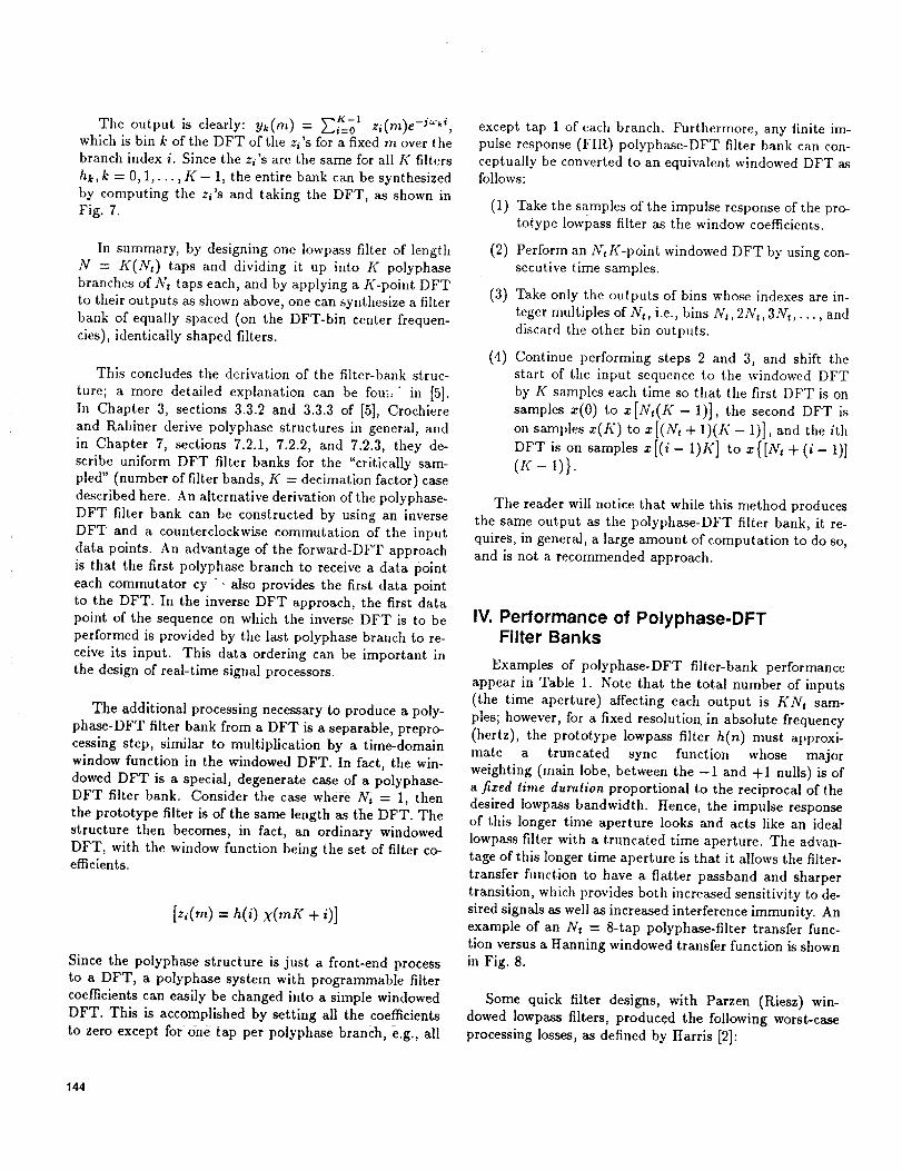
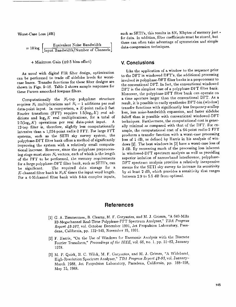
As usual with digital FIR filter design, optimization
can be performed to trade off sidelobe levels for worst-
case losses. Transfer functions for these filter designs areshown in Figs. 9-16. Table 2 shows sample responses for
these Parzen smoothed lowpass filters.
Computationally the Nwtap polyphase structure
requires N, multiplications and Art - 1 additions per real
data-point input. In comparison, a K-point radix-2 fast
Fourier transform (FFT) requires 1.5(logu If) real ad-
ditions and log s K real multiplications, for a total of2.5(log2K ) operations per real data-point input. A
12-tap filter is, therefore, slightly less computationallyintensive than a 1,024-point radix-2 FFT. For large FFT
systems, such as the SETI sky survey system, the
polyFhase-DFT filter bank offers a method of significantly
improving the system with a relatively small computa-
tional increase. However, since the polyphase preprocess-ing stage must store Nt vectors, each of which is tile length
of the FFT to be performed, the memory requirements
for a large polyphase-DFT filter bank, such as SETI's, can
be significant. The required data storage for a
K-channel filter bank is NtK times the input word length.For a 4-Mchannel filter bank with 8-bit complex inputs,
such as SETI's, this results in 8Nt Mbytes of memory just •
for data. In addition, filter coefficients must be stored, but
these can often take advantage of symmetries and simpledata-compression techniques.
V. Conclusions
Like the application of a window to the sequence prior
to the DFT in windowed DFT's, the additional processinginvolved in polyphase-DFT filter banks is a preprocessor to
the conventional DFT. In fact, the conventional windowed
DFT is the simplest case of a polyphase-DFT filter bank.
Moreover, tile polyphase-DFT filter bank can operate ona time aperture larger than the conventional DFT. As a
result, it is possible to easily synthesize DFT-bin (window)transfer functions with significantly less frequency-scallop
loss, less noise-bandwidth expansion, and faster sidelobefailoff than is possible with conventional windowed-DFT
techniques. Furthermore, the computational cost is gener-
ally minimal as compared with that of the DFT. For ex-
ample, the computational cost of a 64-point radix-2 FFT
produces a transfer function with a worst-case processingloss of 1 dB, as defined by Harris in his analysis of win-
dows [2]. Tile best windows in [2] have a worst-ease loss of
3 dB. By recovering much of the processing loss inherent
in windowed-DFT spectrum analysis as well as providing
superior isolation of narrowband interference, polyphase-
DFT spectrum analysis provides a relatively inexpensivemeans for the SETI sky survey to increase its sensitivity
by at least 2 dB, which provides a sensitivity that ranges
between 2.9 to 5.5 dB from optimal.
References
[1] G. A. Zimmerman, B. Charny, M. F. Garyantes, and M. J. Grimm, "A 640-MHz
32-Megachannel Real-Time Polyphase-FFT Spectrum Analyzer," TDA ProgressReport _2-107, vol. October-December 1991, Jet Propulsion Laboratory, Pasa-
dena, California, pp. 132-140, November 15, 1991.
[2] F. IIarris, "On the Use of Windows for IIarmonic Analysis with the Discrete
Fourier Transform," Proceedings of the 1EEE, vol. 66, no. 1, pp. 51-83, January1978.
[3] M. P. Quirk, II. C. Wilck, M. F. Garyantes, and M. J. Grimm, "A Wideband,
IIigh-Resolution Spectrum Analyzer," TDA Progress Report 4_-93, vol. January-
March 1988, Jet Propulsion Laboratory, Pasadena, California, pp. 188-198,May 15, 1988.
145

[4] B. Oliver, "Parametric Relations in a Pull Sky Search," NASA SP _19, NASA,Washington, D.C., p. 129, 1977.
[5] R. Crochiere and L. Rabiner, Multirate Digital Signal Processing, Prentice-Hall
Signal Processing Series, Englewood Cliffs, New Jersey: Prentice-Hall, 1983.
146

Table 1. Examples of polyphase-DFT filter-bank performance
Interference
Worst-case rejection:
Taps per processing offset bins
branch, Nt loss, dB to >70-dBattenuation
2 2.503 7
4 1.513 4
6 1.236 3
8 1.048 3
12 0.653 2
16 0.543 2
Table 2. Sample responses for Parzen smoothed Iowpess filters
Taps per Min. gain at Equivalent noisebranch, Nt 0.5 bin, dB bandwidth, bins/Hz Min. gain, dB Worst-caSeloss,dB
2 -0.492 1.589/30.302 -0.492 2.503
4 -0.244 1.335/25,460 -0.258 1.513
6 -0.128 1.239/23.638 -0.304 1.236
8 -0.077 1.184/22,581 -0.315 1.048
12 -0.295 1.083/20.649 -0.308 0.653
16 -0.252 1.058/20.181 -0.298 0.543
I a -3.908 1.016/19.372 3.976
I b -1,423 1.516/28.908 3.229
Rectangular window.
b HannJng window.
147

f,-1
-2
i-rr0 -4z
-5
-60 0,5 1.0 1,5 2.0 2.5 3.0
BIN NUMBER
Fig. 1. Losses In Hsnningwindowed discrete Fourier transforms (DFTs).
10-21
10-22
¢-4
J
10-23
1 I I I
/ FAST FOURIER TRANSFORM,/ 30-Hz EQUIVALENT NOISE
LEVEL-I / BANDWI_
REQUIREMENT / __
RANGES __._.
z /i _..-"'{_ Y ,..,,'_" _-JDEAL BANDPASi" - -_'- \ S
Oz ///_ FILTER, 20 Hz_- - MATCHED FILTER
rrO_z
10-24 t I [
0 2 4 6 8 10
FREQUENCY, GHz
Fig. 2. A comparison of system sensitivities.
t_
3f_>
ILlC_
5--Z
6- _"oz
7-
I f I 1
flf
if
f IDEAL BANDPASS FILTER, 20 Hz
/
I I i I
2 4 6 8 10
FREQUENCY, GHz
Fig. 3. A comperison of losses relative to the theoretical
optimum.
x(n)--- hk(n ) = h(n) exp(Jwkn ) __--"--'-_ _
Yk (m)
/{1 DECIMATION
Fig. 4. A K:I decimated bandpass filter from a Iowpess prototype.
148

f
Fig. 5. General polyphase structure for the K:I decimated filter hk.
-,--
COMM_ATO"PERIOK :
Fig. 6. Polyphase structure for the kth K:I decimated filter hk, with center frequency_k "-- 2_k/K.
X(I1) • Q •
COMMUTATOR, PERIOD = K . ,, •
K-POINTDFT
Yo(m)
..--
n= K-1, 2K- -_K_l(m) ZK-l('m) FK 1(m)
Fig. 7. Discrete Fourier transform Implementation for a bank of identically spaced, identicallyshaped filters.
149

0_
-20 _ .................
-80 ...............
m
_ -I00 -- -"Z
<
o -120
°,IIn-O -20Z
_,0_!k-60
-80
'rt"....-100
-12o 1t0 1
\
0(c)
=1o
-20
-30
-40 .......
-50 .....
-6O
11lIo_
2 3 4 5 6 7 8 0 0.1 0.2 0.3
BIN NUMBER
\
V%
0,4 03 0.6 0.7 0.8 0.9 1.0
Rg. 8. A comparison of a Hanning windowed discrete Fourier transform with an 8-tap polyphase discrete Fourier transform:
(a) Harming window; (b) 0.6,5-bin Iowpass filter, Parzen smoothed; (c) Harming window, close up; and (d) 0.65-bin Iowpase filter,
Parzen smoothed, close up.
150
0
-20
-40
-60
-80
-10o
-120
o
; , = | !i ! , i
.........._, .......=.........., .........._...................._.........._...........! i i : =1/,, i ! i ,
.... L.-. | ......... .,............... -t .....................................', I/-};_ , + . _- ii I _r\A I i = i 1= ' i i i ".... '..----_--t----7-_A-k.......l..........;........i.......
.......... i- .......... I ......
i i I! i i
i i i i il It: i ! I iI i il iil i ! i i ,I
1 3 4 5 6 7
0
1
2
34
N
5
oz 67
8
0
i ' i i t_........T........T........ ]'"" i = ' i i. : , _ ....T.......1........t........f.........,----_ .......t......1 =__1o........_.........=........- ........:.........;.........•..........,...... - ..... .t....... _ -15
i T , "................................. _ .......
........+........,-........,--..__.I. ........ti i i i i i i i i --,.-20........,........+........-..._-_ ........1
........,+........,........,....__\...1 _>-_i i ! i ! i i i z................-................i.........i.........i................i........i------"4
i i i I -350.1 0.2 0.3 0.4 0.5 0.6 0,7 0,8 0.9 1.0
0
-0.05
-0.10
-0.15
-0.20
-0.25
-0.30
-0.35
-0.40
-0.45
-0.50
........ i........ i ........ i ........_-....... _,"'_'_"i" ....... i......,.i.........i _ "L........i........i........i ........,i.........i....... .i........._ ......i ........i.........
i i i i i ii i ': "x ii i !i i i i i i i i
.........i ........i ........i ........,i........iiiiiiiiiiiiiiiiiiiiiiiiiii_I,I,.......4.........i ........i ...... i.................!........i........i........_......i ! i _ i........I I I , _ !; l I I _ i.........i........i........i........,i......._-.i ......._........i i ! i _ i\_ii i i i
.........i........i........i........_..........., ..... i..._..i i i ,. ... _ _"' * "ii i i _' \
.........i........i........_.......+......_._ ........_......_: I : I I ,'' ' ' li i ' " . i i i i
0 0.05 0.10 0.15 0.20 0,25 0.30 0.35 0.40 0.45 0.50
BIN NUMBER
Fig. 9. Sample response with two close-up views of a 2-tap,
0.95-bin Parzen smoothed Iowpass filter.
Ol " ; ' i ' i.' I , ! I
t ...........l........., .........."_........._.....................i...........-20........., l, i ] i-40 .........._-,<......i....... ..+.........i-.........4..........i-..........t...........
i/I. I I I I I 1I t,SN. ! i i I i
_,o _-rl'_-;:::t- = l..................-.i.........t.........-i....................I...........i
-80 ................................. 1...........
-100 i ......
.........i..........1.........i.......i.........i...........i,.....;--i........0 1 2 3 5 6 7 8
! i i t "',i.. ! t I........ _-........ i ....... !" ....... _ ....... 1"...... _ ....... 1"_"'!" ....... "_...... '_
1 i ' I i : i, , i _ I I i",k. , I........i-........i........4........ I........4-_ .......-I,-..... i-a,_.... I....... 4
I I I I ' I I• t • ' i i , ;, , : | _ ,
I = I ; --3--'] ....... i } I! i i ! i_L_..AS i
........ _-........ i ........ ,=-........ t ....... _---_ ....... p-\-----4
i i i i i i i '........i"........i........'i"........|........_ ........i........"i',......... ........i.......: , , : t i i i i
i i ! i i i : i :: l : i ! i 1 i II: : i : i t : i! • i :; i i i 1
0. I 0.2 0.3 0.4 0.5 0.6 0.7 0,8 0.9 t.0
o........i........,........,........,-........,.......-.'........i.-_., ........,i i ! i i i ilim\i _,i 1 I i. .i. .i i-0,o_...................................................._.._......_.......i i i i ! ,
-0,0.........i........i........i........._.......t...........................
-o.-...............-o.25_ ..... i........t
! ! i i ! ! i i ! I..-0.30 -' | : . ' I I i i
0 0.05 0.10 0.15 0.20 0,25 030 0.35 0.40 0.45 0.50
BIN NUMBER
Fig. 10. Sample response with two close-up views of a 4-tap,0.76-bin Parzen smoothed Iowpass filter.
151

OI \: i i Ii ! : i !I \" ' i l-20 t ........ i'{" .......... i .......... 'I' .......... .'-......... "t .......... t .......... i ...........
! : j i ' ' iI IJ l , , t t ,-4ot........t'_.........!..........,i.........._.........4..........,_..........I..........
I I1_. t I ! l t t, I Ivl,, ! l t . ! t
-6o •..........ttttl/tJ_ .........i"..........f .........-l"......... .l-.........._.........._o ['lll_^^.J i i 1
-12o..........i-........._._. ......i1......:.i I i _ i ii
-14o i i ! ! i0 2 3 4 5 6 7 8
0 i , * i
I i -'!_.: t i i-10 t ........ t- ........ _........ t- ........ *....... * ....... i-----'_4 ........ t- ........ ; ........
l i _ i i i i _ l -'-2oi........_,........!........_,........,,......÷......._.......4-X-..--_........I.......
z -3ot........i.........i ........i.........i.........i........i........4.....-V.,-.......i.........T< i ! i i i _,_: i : !
- 0 ........,"........l........I"........l........_ ........i........_ ................ '.........
,,,r' : : i : : i iI I l l | I * I t
.....N --50 ......... t,......... i ........ t ........ ! ........ ',i- I .........J<
-60 ......... i ......... i ........ _"........ i ........ "L-: ..... j-. ...... 4-_'i'.._-..-.i .........
7o -70 ........." ........!........f ........i........"f......... ..................
_o ,,- t ..+ , +. __ ,....... ........-90
0.1 0.2 0.3 0.4 0.5 0.6 0.7 0.8 0.9 1.0
0 ........,........,........,................;........................o,o........,........,........,........,.......,.......,..............-015........_........_........i........".......•......._........i.......l_i........i........
-o.2o_ ....." ........_...... " : ' ...............', .......I: i _ ! !
i : i i i
0 0.05 0.10 0.15 0.20 0.25 0.30 0.35 0.40 0.45 0.50
BIN NUMBER
Fig. 11. Sample response wlth two close-up views of e 6-tap,
0.69-bin Parzen smoothed Iowpass filter.
0
-20
-40
-60
-80
-100
-12o
-140
I : i l ! i
................... t.......... ' .......... t ......... 4 .......... ,'-.......... i...........
I i I i i i i.... ii_i ...........i..........:i....... ',.........'+.........._..........I...........
IlL 1 t I I I I/ _ i , i ! Ii , : I '
I............ : .................... 1"................. i".......... "..........
.... I " i ,......... ii!!
i :...........,.........._ ......i....:,.it i I : i
i i I i0 2 3 5 6 7
-5
-t0
-15
(,.9-20
iiia•-i -25<
-30oz 35
-4O
-46
....... i- ........ I ........ ; ........ ,...... .I ..... i-----_I ........ l- ....... t .........
......._........!........i........i......l....!.....K....t......i.....L i [ i ! e i\! i
........ , ........ , ........ . ................ 1'........ _ ...... !"'"4r't;_'-"l ........
.......i.. I ' i ! ......i i /f'Xi" ' ....... : ........ I ........ l ........ ?........_'_"-"_,i'_"'_i........ "_...... ,i.....
I l i I i I I l........ i- ........ ' ........ 4- ........ | ........ .i,-o __ - _ _-o----li_ ------,
I I 1 I l il iI,I i 'i i/I i i i ! : : t........ i- ........ , ........ t ........ ' ........ + ........ _ ........ i- ....... -i+------.
i i : i ! _ :!if7. 4. I I I I 1 ! i
...... i ........i........T........i........T........i......... ........i"................
........................................•i ............... ........................t l • [ I l 1 i :
0 0.1 0.2 0.3 0.4 0.5 0.6 0.7 0.8 0.9 1.0
-0.05 ........ l ........ I........ t ........ ,i-....... t ....... t' ........ t ........ I ..... --_-------_li
I I I l l l ' i '' ' , , : ! , /i-0 10 ........ t ........ i ........ i ........ 4........ 4........ 4......... i ........ i----7--i ........
• i i i i i i i i / i
o_ ........I........_........i........".......*.......l........_........#i ........, i . : i : ! :I i
i I ' " ! ' * , l, ,, l I , I l l I i-o2ol........;........,........,......_ .......i........;........i/ ..... i........' : ! I I t
-0.25 ....... _......... i ......................I ; i : l I "l I [ I 1
I i i :: ! i N, _/i i-o3ot ........_-; ...... j........J._ ...... l .........I i _ I ! l i "4"/,' ! iI ! ; I ; 1 , I I '
o351 '_ i ! i _ , i I0 0.05 0. I0 0. t5 0.20 0.25 0.30 0.35 0.40 0.45 0.5'
BIN NUMBER
Fig. 12. Sample response with two close-up views of en 8-1ap,
0.65-bin Parzen smoothed Iowpass filter.
152
i i i :-20 ..... -I-"i" .......... , .......... "i".......... 'l" .................... t ......... i ..........
i : I ! i ! t-40.....-i,-_..........i..........•..........i-........._........i-.........!..........
Illj i ! I I ,ill, I , 1 l 1 I
-60 ........ .;ilk, ........ I ........ ..i........... l........... 4 .......... 4. .......... ! ........I | i !
oo i!'llli,j.". _ t _..........t.......I...... ....!-,4ot.-.._ ..........1........i .....""/ I i i ! ! I ,-16o1--.-_- ......f ........., ........
/ , ! i i ! i l-18o| i ! i i i !
0
-20
-40
-60
-80
-100
-120
-140
-160
0 1 2 3 4 5 6 7 8 0
o _ i i i o-I 0 ........ i" ........ i ........ t ........ ' ........ "i' ........ .it ....... "t ........ i" ....... "i ....... I 0
' ' ' i I iS ! ' i! i i i-20 ........ t ......... i ........ ,m-....... i ........ + ....... i---,t.---.t ........ l- ........ I ........ _ -20
z i i i i i i\! i i __: -3o:........"........"......." ........!........_........!-----t-----......,i-.......i........ _ -30c.B ! l i J i i 1.4"_ I I
,-,, : : i ' ! i I/l\ I I ,':I,,,,, -40 ........ i- ........ i........ ,i-........ i ........ i ...... i.... I!4--1,----,,,i-........ i......... 40
< -5o........" ........}........÷........l............................. ,_" _, -5on- : -" -' i i ; 1 : w
o -60 ........ i- ........ i ........ _ ....... i...................................... o7 -60
-801-70........ L ........ i ........ _......... | ............. "__ ...... _ .... 1 -8070
0 0.1 0.2 0.3 0.4 0.5 0.6 0.7 0.8 0.9 1.0
0
-0.05
-0.10
-0.15
-0.20
-0.25
-0.30
-0.35
I........ I ........ t........ 1........ 'l-....... 't-....... -I' ........ I' ........ I ........ 1""'4r"
l I
i........ I........ i........ t........ l. ....... .I........ ..I......... t ........ i .... .,.....
........i................!........i.......i.......!........!.............i......,
........,........_........,........:.......-__....., ........,..t.._.......
_ ......i----_........7----,......._... ....._, ........,........
i i [ i ', _ , _ !0.05 0.10 0.15 0.20 0.25 0.30 0.35 0.40 0.45 0.50
BIN NUMBER
Fig. 13. Sample response with two close-up views of s 12-tap,0.585-bin Parzen smoothed Iowpass filter.
_! i , i i.....t'_..........I......................t.........l..........i..........i................. ._........... -i .......... .i.......... i-......... 4........... i- .......... ! ..........
I. ! i i I i I.....-Ii .......-4-'........." .........i-...........i.........i-.........I.........
........."_[ ....,"'-i.,"_.........._I, .......F-:-i i i ir I it i : i t I
I 2 4 5 6 7 8
i , F",, i i i iI..., ...............!......&i.........,........L.......J......
........ T ............. t l ' i
........ _ ....... '....... t ........ t ........ , ....... _....... _....... _- ..... -t--_
........_........i........,,.........I........i_-i ......!........i.......i__l i i l ! lkAi I i• ' ' t i t i Ii : ! ............,..........,......., ........,........; .......i-.:4-,x......,-......--,.....! i ! i i i li'.'_ ! i.........:.........,........•........,........i__..._.Fi.._,---_.....i i i i i i iVt 'fl,h........;........i........_........',........_........',........",........_,,+,_
i i' "_ i/
......... _"........ ' ........ _"........ i ........ "_........ t ........ 4 ........ _"........ i.......J i I I li i ! ! '
0 0.1 0.2 0.3 0.4 0.5 0.6 0.7 0.8 0.9 1.0
0.05 i
io ......... l........ '........ '........ I"....... " ....... "_........ i ........ ,........ ,-T,_--' i _ i i i i i i,,
i , ! : : : i I :.1.../_.05 ........ i ........ i ........ i ........ i- ....... + ....... ..i......... I ........ i ........ tl I": : ' : : l i l i
i i i i i : i 1 !/ II I i I i I l I ,"iL..._.-6.1o ........ : ........ 1........ {................ t ................ l .................
i i i i i
_'_5I........i........I........I........t.......i".......I........I........I......'t.:.......1,• _ i i i i i i.......1
°_°lo_o,, , , , , , , L !_i........!........l........t.......i.......i........i....._7i.......10 0.05 0.10 0.15 0.20 0.25 0.30 0.35 0.40 0.45 0.50
BIN NUMBER
Fig. 14. Sample response with two close-up views of a 16-tap,0.565-bin Parzen smoothed Iowpass filter.
153

<(5
OW
Nd<
n-
OZ
0
-10
-20
-30
-40
-50
-60
-70
-80
-90
-I00
0
-10
-20
-30
-40
-50
-60
-70
-80,
-90
-I00
o----*o4_.
.........4
I I . ,
........... , .......... ,. .......... t ......... 1 ..........
+...... ,.,.,,...-::_.-......
.......................... i
ii
........... ! ...........
.........rl........
2 3 4 5 6 7 8
, ; , , ' ' I : %
, , , , • ; ; . ,........ ,........ _ ....... _,_._4........_ .......
........+........+........+__ ........;-__+...._., * , , | ' ! I '
........ , ........ * ....... + ........ , ........ * ....... + ....... _ ........ i ........ .9.....
, . • 8 .* , , ,
......... f ........ _- ....... "9........ ! ........ .9 ....... .9 ....... 1' ........ ! ........ .9 .......
.........;........ ';-....... _........ i........_-....... , ....... 4........+........ ; .......
.........!........ ,;-.......i ........}........ ,_....... "....... _........ i........ '_.......
........ i........ b ....... 4 ........ i ........ 4-....... 4........ 4 ........ ! ........ _........I X " I i I 8 " t,| : ' : , I ; | !
........ t ........ .9 ....... "t ........ ! ........ _- ....... 't" ....... "7 ........ _ ........ .9 ........I I I I I I
I l . I I |
0.1 0.2 0.3 0.4 055 0.6 0.7 0.8 0.9 1.0
• : + : : i i ' i "!
-oo5............. .,-........_........_.......+........-0+_o ........--i--------.,,.---.--.-_...-..-._..------_...i........-i........;........-i.............; ........i........_........4 .........
-o.15 ...... --i------'-_'-------!--------_--------_----} ........ _ ....... , .........
! It I I : " _ Ii } { i : _ ' !
-0.25 ....... T ......................... .:......................
-0.30 ........ 0........ _ ........ +........ _ ........ g........ .9........ i ........ _ ...... _- ....... 4
-03_.............................-..................................,r.......-0.40 : _ _ ! [ i i i, h
0 005 0_0 0._5020 02_ 0_0035 0_0 045050BIN NUMBER
Fig. 15. Sample response with two close-up views of a rectan-
gular window.
£Q
Z
(5
mN
.J<
m
o
o
-50
-100
-t 50
-200
-250
-300
.....i..........i.........I........i
t i
i i
I
0 1 2 3
ii
.......... ..........
I..........4 .......
i
!
I
|I
5 6 7 8
0 : " ' : I I t I
-_ ........_-+-_--_-._------i .........i........4........-,........+.........; I ' l • l i I I
I I I I ; _ ,"' , I I , : ! l :-2........_---,-------_ ........+........+........+........
+........!........i........i.......i.........i.........i........+......-'........+......................................................+-4, ........_- '-..--.--+..__ .....i.-..-...i...... " ........+'_.....'.I..........
! I ; , l i : ; :
-st........:_:-Ni' I I "I : I I , I , ; ,-oi........_,...---._.-+"_ ....+....-.N.
_,l i i _ I0 0.1 0.2 0.3 0+4 0.5 0.6 0.7 0.8 0.9 1.0
-02 ................. ........t..... ........ ........ ..... i ........_........_........-0.4 ................ i........ i ........ 4 .........
_ .,"_ ii l i i : , ' .' '-0,6 ....... __'i ........ _ ....... _ .........
i i i i I ! "k.' :' ' l i : ' '_ :-0.8 ....... 4_...+ ........ 1..-_-4 ...... 4 .........
, ; I l I : i ; "-+.2 .......__i ........+"x......It i i i i\l
l i i : i ' ' ; :_14......._--V----Ni i i ! ! ! i _ i 1
-_.6 ! ! _ i i I ! ! I| | | i, _ I _ ' l
0.05 0,10 0,15 0.20 0,25 0.30 0.35 0,40 0.45 0550
BIN NUMBER
Fig. 16. Sample response wllh two close-up views of a Hannlng
window.
154