polypropylene laminated paper (pplp) insulation for hvdc ... · hvdc power transmission systems...
TRANSCRIPT

Polypropylene Laminated Paper (PPLP) Insulation for
HVDC Power Cables
George Chen and Zhiqiang Xu
The Tony Davies High Voltage Laboratory
University of Southampton UK
Abstract - Space charge is a major issue that hinders the
development of HVDC polymeric cables. On the other
hand, HVDC cables with polypropylene laminated
paper (PPLP) insulation has been in operation for a
long time with a good record. In the present paper, the
electrical performance of PPLP insulation has been
studied to understand the reasons for its excellent
characteristics. It has been found that the charge
accumulated at the interface between PP and Kraft
paper plays a key role in determining electrical
performance of PPLP insulation. The formation of the
interfacial charge results in an optimal electric field
distribution for PPLP insulation system as well as a
small and electric field independent conductivity.
I. INTRODUCTION
HVDC power transmission systems have received significant
attention as they offer many advantages over HVAC systems in
terms of grids connectivity, system reliability and off-shore
wind farms etc. As a result, HVDC power cables have
experienced a significant development in last ten years. Many
efforts have been placed on developing polymeric insulated
cables. As a result, insulation based on improved XLPE,
nanocomposite and thermoplastic have been developed for
HVDC power cables at 400 kV and above [1]. However, less
attention has been placed on the insulation based on
polypropylene laminated paper (PPLP). PPLP has been widely
used for HV power cables including HVDC due to its excellent
electrical and mechanical performances. Its use for power cable
insulation can be traced back to 1970’s, initially for HVAC
cables but extended to HVDC cables and superconducting
cables [2-3]. Figure 1 shows a typical PPLP insulated cable
structure and PPLP insulation tape.
Figure 1 A typical structure of MI HVDC cable and PPLP insulation.
This type of structure shows a higher AC, impulse and DC
breakdown strengths as well as lower dielectric loss compared
with the conventional Kraft paper insulation. When compared
with XLPE insulation the publications on PPLP insulation
available in the public domain are limited and the exact
mechanisms for the improved electrical performance are not
well understood, especially for HVDC cables. Space charge is
a major issue that has been highlighted in all insulation for
HVDC applications. Therefore, it becomes increasingly
important to understand charge dynamics in PPLP insulation
system and its influence on the electrical performance of HVDC
cables.
In the present paper, charge dynamics in both single and multi-
layered PPLP films have been studied experimentally using the
pulsed electroacoustic technique (PEA). DC electric breakdown
and conductivity for PPLP films have also been measured. It
has found that the interface between the Kraft paper and
polypropylene acts as barrier that hinds the movement of charge
carriers. As a result, the electric field distribution in such a
system has been significantly modified with the highest electric
field in PP and lower electric field in Kraft paper. Similar
pattern has been observed in the case of multi-layered PPLP
sample while the interface between Kraft papers shows no
effect of charge blocking. This type of electric field distribution
works favourably for the overall electrical performance of the
PPLP insulation system.
II. SAMPLE PREPARATION AND
EXPEREIMENTAL DETAILS
Sample preparation
PPLP laminated insulation consists of one layer of
polypropylene sandwiched between two Kraft paper layers. The
samples used in the present study has a total thickness of ~120
µm (25 µm + 70 µm + 25 µm). The compound used for
impregnation is a high viscosity DDB oil (H&R T2015) which
is commercially available. The samples were dried in vacuum
oven at 100ºC before the impregnation process. The DDB oil
was degassed at 100 ºC for 24 hours. Impregnation was carried
out at 100 ºC in a vacuum oven for 2 days. After being fully
impregnated, the samples were kept in vacuum until tests.
Space charge measurement
Space charge distributions were measured by the pulse
electroacoustic technique (PEA). It relies on the interaction of
the applied pulsed electric field and the charge in the sample,
launching acoustic waves that are detected by a transducer

attached to one of the electrodes. Through calibration and
deconvolution processes, the detected signal can be converted
into charge distribution across the sample. To understand
charge dynamics in PPLP insulation, single layer Kraft paper
and PP were also measured under different electric fields.
Typically, the measurements lasted 30 minutes after the
external voltage was applied and further 10 minutes after the
removal of the external voltage. Since the moisture content is
one of the most sensitive factors for oil-paper insulation, the
impregnated oil moisture was controlled less than 10ppm. All
the experiments were carried out under controlled humidity.
The space charge measurements were started after the
temperature became stable and data were collected regularly for
30 minutes.
DC electrical breakdown and conductivity measurements
DC breakdown for Kraft paper, PP and PPLP was measured
according to the ASTM D1816. A pair of spherical electrodes
were used and the sample was sandwiched between them.
Electrodes were rotated after each breakdown to avoid the
effect of pitting and replaced after 20 breakdowns. The voltage
rise rate is 200V/s and the data were processed using the
Weibull statistics.
Electrical conductivity for oil impregnated Kraft paper, PP and
oil impregnated PPLP samples was measured for 60 minutes at
20 oC and 60 oC under different applied voltages.
III. RESULTS
Space charge results
Figure 2 shows space charge in 50 µm Kraft paper
impregnated with DDB oil under 20 kV/mm and 50 kV/mm at
room temperature. Homecharges are observed soon after the
application of the external voltage, indicating charge injection
taking place from the both electrodes. This is further confirmed
by the charge profiles after the removal of the external voltage.
Figure 2 Space charge dynamics in oil impregnated Kraft paper during volts-
on and decay (room temperature): left – 20 kV/mm and right – 50 kV/mm.
When the applied electric field increases, more charges are
injected as evidenced in Figure 2 (right hand side). Both
positive and negative charges are reasonably
balanced/symmetrical under 20 kV/mm and 50 kV/mm. This
observation is more explicit after the removal of the applied
electric fields. When the measurement temperature is increased
to 60 oC, the movement of charge into the bulk is more obvious,
especially for negative charge as shown in Figure 3. Negative
charges dominate after the removal of the applied field. It is also
believed that more charges may be injected into the sample at
higher temperature under the same applied electric field. The
charge decay is relatively slow at room temperature but
enhanced at 60 oC. These results are consistent with our
previous results [4].
Figure 3 Charge dynamics in oil impregnated Kraft paper during volts-on and
decay at 60 oC: left – 20 kV/mm and right – 50 kV/mm.
Figure 4 Charge dynamics in oil impregnated PP during volts-on and decay
(room temperature): left – 20 kV/mm and right – 50 kV/mm.
Figure 4 illustrates charge dynamics in 50 µm PP film
obtained at room temperature at 20 kV/mm and 50 kV/mm
respectively. It can be seen that the charge injection also occurs
at 20 kV/mm as this electric field is exceeding the threshold
electric field and the injection becomes stronger at higher
electric field as expected. However, it seems that the negative
charge injection plays a crucial role in the charge formation of
PP film. Similarly, when increasing the temperature to 60 oC
more charges are injected in the sample, dominated by negative
charge under 20 kV/mm but significant increase in positive
charge under 50 kV/mm as shown in Figure 5. At 60 oC the
charge buildup in PP film is more obvious and charge decay

after the removal of the applied field is less fast comparing with
that in Kraft paper at the same temperature.
Figure 5 Charge dynamics in oil impregnated PP during volts-on and decay at
60 oC: left – 20 kV/mm and right – 50 kV/mm.
Figure 6 shows the charge distribution in PPLP at room
temperature. As this is the structure used in HVDC cable,
charge dynamics under three electric fields were investigated,
i.e. 10, 30 and 50 kV/mm. It can be seen that charge reaches to
a qusi-steady state at 30 minutes after the application of electric
field. Several features can be identified: (i) quick formation of
charge at the interfaces (ii) charge at the interface has the same
polarity as the closer electrode (iii) the amount of charge at the
interface increases with the applied electric field (iv) charge
decay after the removal of the field is slow.
Figure 6 Charge dynamics in PPLP samples at room temperature under 10, 30
and 50 kV/mm.
When increasing the temperature to 60 oC, the buildup of
charge at the interfaces is much fast as shown in Figure 7. It
seems that the electrodes shift their positions. As a result, the
amount of charge at the interfaces is significantly higher than
that at room temperature for the same applied electric field. The
time required for the interfacial charge buildup decreases with
the applied electric field. Higher temperature also enhance
charge dissipation from the sample once the applied field is
removed.
Figure 7 Charge dynamics in PPLP samples at 60 oC under 10, 30 and 50
kV/mm.
Electrical breakdown strength
Electric breakdown under dc fields is often related to charge
dynamics in the material. Generally, to reduce
discharge/flashover, electrical breakdown test is conducted
with sample/electrodes immersed in low viscosity silicone oil
or transformer oil. However, considering PPLP insulted cable
where high viscosity DDB is used, a comparison for PP in both
type of oils is made as shown in Figure 8.
Figure 8 Influence oil on breakdown strength of PP.
It can be seen the breakdown strength of PP in silicone oil is
higher than that of DDB. At room temperature, the viscosity of
DDB for MI cable is significantly higher than silicone oil,
therefore, it is believed that it is extremely difficulty to
eliminate pocket cavity. This will lead to a lower breakdown
strength as the breakdown voltage is the characteristic of
oil/sample system. It is worthy of pointing out that the
characteristic breakdown strength (63.2%) of PP even in DDB
oil is still beyond 450 kV/mm. In reality, PP is laminated
between two Kraft papers and the oil impregnation is typically

carried out in vacuum at high temperature. The probability that
voids/cavities can form is much less.
Figure 9 shows the Weibull plot for DDB impregnated Kraft
paper and the influence of moisture on the breakdown strength.
It is clear that significant impact of moisture on breakdown
strength of oil impregnated Kraft paper as expected [5].
Figure 9 Weibull plot for DDB impregnated Kraft paper and the influence of
moisture.
Figure 10 Weibull plot of oil impregnated PPLP and the influence of
moisture.
DC conductivity
DC conductivities for Kraft paper, PP and PPLP were
measured at room temperature and 60oC. The conduction
current for both PP and Kraft paper at room temperature is very
low. For the sake of clarity, only the conductivity at 60oC is
shown in Figure 11. Figure 11 (a) illustrates the conductivity
change of DDB impregnated Kraft paper with the applied
voltages. As expected, the conductivity increases with the
voltage (electric field for the fixed ample thickness). Significant
increase in conductivity at 5 kV (50kV/mm) and the sample
failed after just stressing for 20 min. This is not surprising as
the electric field applied is above the characteristic breakdown
strength of the DDB impregnated Kraft paper. The conductivity
of PP film also increases with the applied electric field as shown
in Figure 11 (b). However, the conductivity of DDB
impregnated PPLP seems independent of the applied electric
field as observed in Figure 12 (c). The observation is surprising.
(a)
(b)
(c)
Figure 11 Conductivity versus the applied voltages.
IV. DISCUSSION
The presence of charge in the insulation system alters the
electric field distribution. Local electric field enhancement may
lead to regional material deterioration. This may affect the
electrical performance of insulation system and reduce the
reliability of high voltage equipment. For the PPLP insulated
HVDC cables, the situation is slightly complicated as the
electrical breakdown strength Kraft paper is significantly
weaker than that of PP film. The uniform electric field
distribution is not beneficial for the reliable operation of such
insulation system. Therefore, it is important to obtain electric
field distribution from space charge measurements. Figure 12
shows the electric field evolution in PPLP over the period of 50
min after application of the voltage. The applied electric field is
about 8 kV/mm. After 50 min the electric field in PP almost
doubled while the electric field in Kraft paper decreases
significantly. This type electric field distribution is highly
desirable as PP is electrically stronger and is able to take extra
electric field without deteriorating its electrical performance.
-5.00E-16
5.00E-16
1.50E-15
2.50E-15
3.50E-15
0 1000 2000 3000
Kraft Paper + DDB Oil 0.1mm 60 °C
2 kV
3 kV
4 kV
5 kV
-1.00E-15
1.00E-15
3.00E-15
5.00E-15
7.00E-15
0 1000 2000 3000
PP 0.05mm 60 °C
5 kV
8 kV
10 kV
-5.00E-16
1.50E-15
3.50E-15
0 1000 2000 3000
PPLP + DDB Oil 0.16mm 60 °C
4 kV
6 kV
8 kV
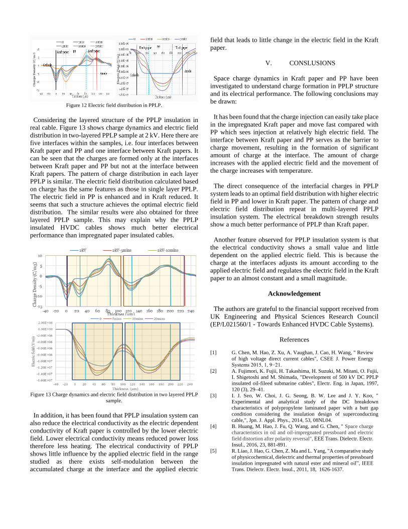
Figure 12 Electric field distribution in PPLP.
Considering the layered structure of the PPLP insulation in
real cable. Figure 13 shows charge dynamics and electric field
distribution in two-layered PPLP sample at 2 kV. Here there are
five interfaces within the samples, i.e. four interfaces between
Kraft paper and PP and one interface between Kraft papers. It
can be seen that the charges are formed only at the interfaces
between Kraft paper and PP but not at the interface between
Kraft papers. The pattern of charge distribution in each layer
PPLP is similar. The electric field distribution calculated based
on charge has the same features as those in single layer PPLP.
The electric field in PP is enhanced and in Kraft reduced. It
seems that such a structure achieves the optimal electric field
distribution. The similar results were also obtained for three
layered PPLP sample. This may explain why the PPLP
insulated HVDC cables shows much better electrical
performance than impregnated paper insulated cables.
Figure 13 Charge dynamics and electric field distribution in two layered PPLP
sample.
In addition, it has been found that PPLP insulation system can
also reduce the electrical conductivity as the electric dependent
conductivity of Kraft paper is controlled by the lower electric
field. Lower electrical conductivity means reduced power loss
therefore less heating. The electrical conductivity of PPLP
shows little influence by the applied electric field in the range
studied as there exists self-modulation between the
accumulated charge at the interface and the applied electric
field that leads to little change in the electric field in the Kraft
paper.
V. CONSLUSIONS
Space charge dynamics in Kraft paper and PP have been
investigated to understand charge formation in PPLP structure
and its electrical performance. The following conclusions may
be drawn:
It has been found that the charge injection can easily take place
in the impregnated Kraft paper and move fast compared with
PP which sees injection at relatively high electric field. The
interface between Kraft paper and PP serves as the barrier to
charge movement, resulting in the formation of significant
amount of charge at the interface. The amount of charge
increases with the applied electric field and the movement of
the charge increases with temperature.
The direct consequence of the interfacial charges in PPLP
system leads to an optimal field distribution with higher electric
field in PP and lower in Kraft paper. The pattern of charge and
electric field distribution repeat in multi-layered PPLP
insulation system. The electrical breakdown strength results
show a much better performance of PPLP than Kraft paper.
Another feature observed for PPLP insulation system is that
the electrical conductivity shows a small value and little
dependent on the applied electric field. This is because the
charge at the interfaces adjusts its amount according to the
applied electric field and regulates the electric field in the Kraft
paper to an almost constant and a small magnitude.
Acknowledgement
The authors are grateful to the financial support received from
UK Engineering and Physical Sciences Research Council
(EP/L021560/1 - Towards Enhanced HVDC Cable Systems).
References
[1] G. Chen, M. Hao, Z. Xu, A. Vaughan, J. Cao, H. Wang, " Review
of high voltage direct current cables", CSEE J. Power Energy
Systems 2015, 1, 9−21.
[2] A. Fujimori, K. Fujii, H. Takashima, H. Suzuki, M. Mitani, O. Fujii,
I. Shigetoshi and M. Shimada, "Development of 500 kV DC PPLP
insulated oil-fileed submarine cables", Electr. Eng. in Japan, 1997,
120 (3), 29–41.
[3] I. J. Seo, W. Choi, J. G. Seong, B. W. Lee and J. Y. Koo, "
Experimental and analytical study of the DC breakdown
characteristics of polypropylene laminated paper with a butt gap
condition considering the insulation design of superconducting
cable,", Jpn. J. Appl. Phys., 2014, 53, 08NL04.
[4] B. Huang, M. Hao, J. Fu, Q. Wang, and G. Chen, " Space charge
characteristics in oil and oil-impregnated pressboard and electric
field distortion after polarity reversal", EEE Trans. Dielectr. Electr.
Insul., 2016, 23, 881-891.
[5] R. Liao, J. Hao, G. Chen, Z. Ma and L. Yang, "A comparative study
of physicochemical, dielectric and thermal properties of pressboard
insulation impregnated with natural ester and mineral oil”, IEEE
Trans. Dielectr. Electr. Insul., 2011, 18, 1626-1637.