poly(vinylidene fluoride) membranes by an ultrasound assisted phase
DESCRIPTION
artTRANSCRIPT

7/15/2019 Poly(Vinylidene Fluoride) Membranes by an Ultrasound Assisted Phase
http://slidepdf.com/reader/full/polyvinylidene-fluoride-membranes-by-an-ultrasound-assisted-phase 1/7
Poly(vinylidene fluoride) membranes by an ultrasound assisted phase
inversion method
Mi-mi Tao, Fu Liu ⇑, Li-xin Xue ⇑
Ningbo Institute of Materials Technology & Engineering, Chinese Academy of Sciences, 519 Zhuangshi Road, Ningbo 315201, China
a r t i c l e i n f o
Article history:
Received 23 February 2012
Received in revised form 21 July 2012
Accepted 28 August 2012
Available online 5 September 2012
Keywords:
PVDF membrane
Ultrasound
Morphology
Phase inversion
Cavitation
a b s t r a c t
Poly(vinylidene fluoride) (PVDF) membranes were prepared by an ultrasound assisted phase inversion
process. The effect of ultrasonic intensity on the evolution of membrane morphology with and without
the addition of pore former LiCl during precipitation process was comprehensively investigated. Besides
the inter-diffusion between the solvent and nonsolvent, the ultrasonic cavitation was thought to have
significant influences on phase inversion and the resultant membrane morphology. The mutual diffusion
between water and solvent during the ultrasound assisted phase inversion process was measured. The
crystalline structure was detected by wide angle X-ray diffractometer (WAXD). The thermal behavior
was studied by differential scanning calorimeter (DSC). The mechanical strength, forward and reverse
water flux, rejection to bovine serum albumin (BSA) and pepsin were also investigated. By the ultrasound
assisted phase inversion method, ultra-filtration membrane was successfully prepared, which exhibited
more preferable morphology, better mechanical property and more favorable permeability without sac-
rificing the rejection and thermal stability.
Ó 2012 Elsevier B.V. All rights reserved.
1. Introduction
Poly(vinylidene fluoride) membrane usually prepared by phase
inversion is widely used in micro-filtration and ultra-filtration pro-
cess due to its superior physical and chemical properties. Depend-
ing on the precipitation rate, PVDF membranes can be: (a)
asymmetric, with a selective skin or large voids on a spongy sub-
layer or (b) symmetric, with an almost even porosity along the
thickness. It has been investigated that many parameters influence
the precipitation process and ultimately the morphologies and the
filtration performance of the membranes, including the composi-
tion of casting solution [1–4], precursor preparation [5,6], evapora-
tion time [7], the harshness and temperature of the coagulation
bath [8–11], etc. The phase separation behavior of PVDF/solvent/
H2O system is far more complex than amorphous polymer systemdue to the semi-crystal nature. Both liquid–liquid demixing and li-
quid–solid (crystallization) demixing are usually occurred during
the phase inversion process of PVDF membrane. These two mech-
anisms are developed to different extents according to the thermo-
dynamics and mass transfer properties. Bottino [12] prepared
PVDF membranes by casting and coagulating solutions of the poly-
mer in eight solvents and found a good correlation between sol-
vent–nonsolvent diffusivity and the membrane structure.
Numerous researches also revealed that thermodynamics have less
influence on the structures and performance of the final PVDFmembranes, while the kinetic mass transfer is the key factor to
control the membrane structure and formation [13–15].
It is known that ultrasound can induce a wide range of chemical
and physical consequences. In liquids irradiated with ultrasound,
ultrasonic cavitation serves as the primary mechanism for sono-
chemical effects, where bubble collapse produces intense local
heating, high pressures, microjet, turbulence, acoustic streaming,
etc. [16–18]. Physical effects of ultrasound include enhanced mass
transfer, emulsification, bulk thermal heating and various effects
on solids. Diverse applications of ultrasound have been explored.
Nanostructured materials, nanometer colloids and protein micro-
spheres can all be prepared by this general route [19,20]. Besides,
ultrasound is evidenced as a powerful tool to polymerize [21], de-
grade polymer [22,23] and disperse nanoparticles [24,25], and it iswidely used in the bulk or surface modification of polymers [26].
With respect to membranes for separation, ultrasound is usually
utilized in membrane cleaning [27,28]. In consideration of the
facilitation of ultrasound during physical or chemical process, it
has the potential to assist the mass transfer between the solvent
and nonsolvent, crystallization growth and structure evolution
during phase separation of polymeric membranes. To the best of
our knowledge, the role of ultrasound in phase inversion process
of PVDF membrane has not been studied. Here, PVDF membranes
were prepared by an ultrasound assisted phase inversion tech-
nique. The effect of ultrasonic intensity on membrane morphology
was investigated. The crystalline structure, thermal stability,
1350-4177/$ - see front matter Ó 2012 Elsevier B.V. All rights reserved.http://dx.doi.org/10.1016/j.ultsonch.2012.08.013
⇑ Corresponding authors. Tel.: +86 574 86685256; fax: +86 574 86685186 (F. Liu),
tel.: +86 574 86685831; fax: +86 574 86685186 (L.-x. Xue).
E-mail addresses: [email protected] (F. Liu), [email protected] (L.-x. Xue).
Ultrasonics Sonochemistry 20 (2013) 232–238
Contents lists available at SciVerse ScienceDirect
Ultrasonics Sonochemistry
j o u r n a l h o m e p a g e : w w w . e l s e v i e r . c o m / l o c a t e / u l t s o n

7/15/2019 Poly(Vinylidene Fluoride) Membranes by an Ultrasound Assisted Phase
http://slidepdf.com/reader/full/polyvinylidene-fluoride-membranes-by-an-ultrasound-assisted-phase 2/7
mechanical property and permeability of membranes were also re-
ported in this paper.
2. Experimental
2.1. Materials
Commercial PVDF (FR904) was purchased from 3F company(Shanghai, China) and was dried at 80 °C in the oven for 24 h prior
to use. N ,N -dimethylfoemamide (DMF,P99.0%) and bovine serum
albumin (BSA Fraction V, Mn = 67,000) were purchased from Sin-
opharm Chemical Reagent Co. Ltd., China and Sigma Aldrich,
respectively. Lithium chloride (LiCl, P99.0%) and pepsin
(Mn = 35,000) were purchased from Aladdin Reagent Co. Ltd.,
China. All materials were used as received.
2.2. Membrane preparation
Fifteen percent by weight PVDF was dissolved in DMF at 80 °C
with a constant stirring rate for 24 h to obtain a homogenous cast-
ing solution. Moreover, six percent by weight LiCl based on the
solution weight was added to the same PVDF solution and dis-solved under the same condition. The casting solutions were kept
still at 80 °C for another 24 h and went through vacuum deaeration
to remove air bubbles.
The casting solutions were uniformly spread onto a glass plate
by a casting knife with the thickness of 200lm. The glass plate
and casting knife were heated to 80 °C before casting in order to
minimize the effect of surrounding temperature on phase inver-
sion. After the nascent film was evaporated in the air for 10 s, it
was transferred into the coagulation bath composed of deionized
water in the ultrasonic instrument (40 Hz, KQ-300DB, Kunshan,
China) and irradiated by ultrasound. The temperature of coagula-
tion bath was kept constant at 28 °C. In one minute, the mem-
branes were automatically peeled off from the glass plate and
taken out from the ultrasonic bath. The solidified membrane was
finally transferred to the fresh deionized water for 24 h to remove
the residual solvents. Therefore, the thermal effect of ultrasonic
irradiation on the coagulation bath could be ignored in one minute.
The solidified membrane was finally transferred to the fresh deion-
ized water for 24 h to remove the residual solvents. Subsequently,
the membranes were dried at room temperature. The preparation
conditions for various membranes are summarized in Table 1.
2.3. Membrane characterization
Morphological structures of the prepared PVDF membranes
were examined by scanning electron microscope (SEM, S-4800,
Hitachi, Japan). The cross section samples were fractured in liquid
nitrogen. Both the surface and cross section of the samples were
sputtered gold for 2 min for observation.To determine the mutual diffusion between water and solvent
during the membrane formation process via phase inversion, the
water and DMF contents in the membranes at a fixed time after
immersion into the ultrasonic bath were measured as follows:
the nascent membrane was immersed in the coagulation bath for
5 s and then taken out to wipe off water drop adhered to the mem-
brane surface, afterwards, the wet membranes were transferred to
specific amount (mmethanolðwaterÞ) of methanol (to extract water from
the membrane) and deionized water (to extract DMF from the
membrane), respectively and then preserved under seal. The lixiv-
ium was analyzed by coulometer (KF831, Metrohm, Switzerland)and UV–VIS–NIR spectrometer (Lambda 950, Perkin Elmer, US) at
197 nm, respectively to get the concentration of water (c H2 O) and
DMF (c DMF). Then the wet membranes should be dried to obtain
dry weight (mdry) and the contents of water and DMF (M water DMFð Þ)
can be calculated using the following equation:
M water DMFð Þ ¼C H2O DMFð Þ Â mmethanolðwaterÞ
mdry
ð1Þ
Crystalline structure of the membrane was analyzed by wide
angle X-ray diffractometer (WAXD, D8 Advance, Bruker, Germany).
All samples were detected in a continuous scan mold between 5°
and 60° 2h with the scanning speed of 0.2 s/step.
The thermal behavior of the membrane was determined by dif-
ferential scanning calorimeter (DSC) (Pyris Diamond, Perkin Elmer,US). The temperature was raised from 25 to 250 °C at a rate of
10 °C/min at a nitrogen atmosphere.
Crystallinity of the membrane was calculated by melting heat
based on the fusion enthalpy of ideal PVDF crystal ðDH f 0 ¼ 105 J=gÞ:
Crystallinity ¼DH sample
DH 0 f ð2Þ
where, DH sample is the melting heat of the sample obtained by DSC
curve.
Mechanical properties of the membranes were determined
using a tensile tester (5567, Instron, US) with the stretching rate
of 5 mm/min at room temperature. Each sample was cut into
10 Â 1 cm, and the thickness of the sample was measured accord-
ing to the SEM pictures.Pure water flux of PVDF membranes were measured by a cross
flow filtration system (Saifei company, China) (the effective mem-
brane area = 24 cm2). The measuring protocol was as follows: In
the first 40 min, the membrane was compacted at 0.15 MPa to
diminish the compaction effect and obtain the stable flux, and then
the flux was measured at 0.1 MPa. Water flux reported in this work
was the final steady flux. Afterwards, pure water was changed to
1 g/L BSA or pepsin solution. The protein concentration of both
feed and permeate solutions were examined by UV–VIS–NIR spec-
trometer (Lambda 950, Perkin Elmer, US) at 280 nm (BSA) or
270 nm (pepsin). The rejection to protein (R (%)) of the membranes
was calculated using the following equation [29]:
Rð%Þ ¼ 1 À A1 A0
 100 ð3Þ
Where A1 is the absorption value of the permeate solution, and
A0 is the absorption value of the feed solution.
Table 1
Preparation conditions for PVDF membranes and diffusion content of water and DMF at fixed time 5s.
Code LiCl/PVDF/DMF (wt/wt/wt) Ultrasonic intensity (W) Water contenta (g/g) DMF contenta (g/g) DMF diffusion amounta,b (g/g)
M1 0/15/85 0 0.392 3.263 2.404
M2 0/15/85 180 0.673 2.515 3.152
M3 0/15/85 300 0.545 1.675 3.992
MA1 6/15/85 0 – – –
MA2 6/15/85 180 – – –
MA3 6/15/85 300 – – –
a
Water or DMF content in one gram of PVDF membrane.b Calculated based on 15 wt.% solid content: 8515 À M DMF.
M.-m. Tao et al./ Ultrasonics Sonochemistry 20 (2013) 232–238 233
7/15/2019 Poly(Vinylidene Fluoride) Membranes by an Ultrasound Assisted Phase
http://slidepdf.com/reader/full/polyvinylidene-fluoride-membranes-by-an-ultrasound-assisted-phase 3/7
3. Results and discussion
3.1. Membrane morphologies
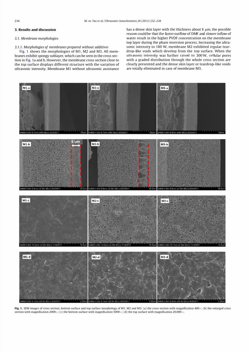
3.1.1. Morphologies of membranes prepared without additives
Fig. 1 shows the morphologies of M1, M2 and M3. All mem-
branes exhibit spongy sublayer, which can be seen in the cross sec-
tion in Fig. 1a and b. However, the membrane cross section close tothe top surface displays different structure with the variation of
ultrasonic intensity. Membrane M1 without ultrasonic assistance
has a dense skin layer with the thickness about 8lm, the possible
reason could be that the faster outflow of DMF and slower inflow of
water result in the higher PVDF concentration on the membrane
top layer during the phase inversion process. Increasing the ultra-
sonic intensity to 180 W, membrane M2 exhibited regular tear-
drop-like voids which develop from the top surface. When the
ultrasonic intensity was further raised to 300 W, cellular pores
with a graded distribution through the whole cross section areclearly presented and the dense skin layer or teardrop-like voids
are totally eliminated in case of membrane M3.
Fig. 1. SEM images of cross section, bottom surface and top surface morphology of M1, M2 and M3: (a) the cross section with magnification 400Â; (b) the enlarged crosssection with magnification 2000Â; (c) the bottom surface with magnification 5000Â; (d) the top surface with magnification 20,000Â.
234 M.-m. Tao et al./ Ultrasonics Sonochemistry 20 (2013) 232–238

7/15/2019 Poly(Vinylidene Fluoride) Membranes by an Ultrasound Assisted Phase
http://slidepdf.com/reader/full/polyvinylidene-fluoride-membranes-by-an-ultrasound-assisted-phase 4/7
Usually, pseudo binary (solvent and nonsolvent) diffusion the-
ory is adopted to describe the early phase separation stage of
membrane formation [30], which reproduces with good agreement
the experimental data and observations. There is evidence that a
high diffusion rate of nonsolvent gives rise to membrane with large
voids beneath the top surface [15]. Based on this and the relevant
morphology variation of the membrane cross section close to the
top skin layer, it can be inferred that the water diffusion rate intothe PVDF/DMF nascent film during the incipient phase separation
moments following the order: M2 > M3 > M1. The contents of
water and DMF in the membranes at a fixed time 5 s after immer-
sion were measured to predict the mutual diffusion rate between
water and DMF. As depicted in Table 1, water content in the mem-
brane, representing the water diffuse rate from the coagulation
bath to the membrane, reaches a maximum (0.673 g/g) when the
ultrasonic intensity is 180 W corresponding to M2, thus leading
to the formation of teardrop-like voids on the top skin layer. The
diffusion amount of DMF into the coagulation bath calculated
based on the initial composition of the casting solution and the
residual quantity progressively increases with increasing the ultra-
sonic intensity. It is well known that ultrasound can promote the
molecule movement and therefore increase the diffusion rate of
DMF. However, ultrasonic irradiation with 300 W intensity does
not further accelerate water diffusion as expected (water content:
0.545 g/g). The exceptional diffusion behavior may be the result of
stronger hydrogen bonding between the water molecules and the
carbonyl group of the DMF molecules. Petersen has pointed out
that hydrogen bonding interaction between water molecules and
carbonyl oxygen are stronger than between water molecules
[31]. In case of DMF, a special amide in view of the lack of hydrogen
bonding in the pure solvent, this effect may be strengthened by the
nitrogen atom due to the resonance forms [32]. Ultrasonic irradia-
tion promotes the mass transfer of DMF from higher concentration
zone to lower concentration zone, while the diffusion of water was
not only affected by the ultrasonic intensity, but also affected by
the hydrogen bonding interaction between water and DMF. There-
fore, despite the high-intensity ultrasound (300 W), water diffu-sion rate in the early stage of M3 is still lower than that of M2,
leading to the formation of a uniform structure with cellular pores.
The morphology of the bottom surface of the membrane also
varies with the variation of ultrasonic intensity used. AsFig. 1c pre-
sents, M1 has a dense bottom surface composed of syncretic
spherulites, while M2 and M3 exhibit porous surface with massive
inter-connected pores. As we all know, the bottom surface con-
tacted with the glass plate is far from the membrane/water inter-
face, therefore, the water/DMF diffusion has less effect on
structure evolution during phase inversion. The main factor is
the ultrasonic cavitation, which produces high-energy phenome-
non and is responsible for the generation of surface damage [33].
We believe that the impingement of shockwaves and microjets
on the surface creates the localized erosion. With the increase of ultrasonic intensity, erosion becomes more severe and finally leads
to the formation of completely porous surface. All membranes
present a dense top surface as can be shown in Fig. 1d. The delayed
phase separation leads to the evaporation of solvent and higher
polymer concentration. After the casted nascent film on the glass
plate is immersed into deionized water, the fast mass transfer at
the interface between water and film results in instantaneous
solidification of top surface, therefore, a dense top surface was
formed in all cases.
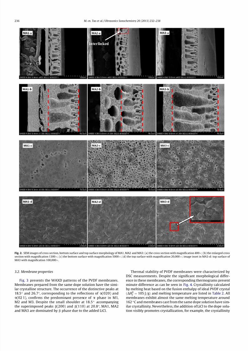
3.1.2. Morphologies of membranes prepared with LiCl
The effect of ultrasonic irradiation on morphologies of mem-
branes prepared with pore former can also be identified. When
6% by weight LiCl is used, all the membranes exhibit highly inho-mogeneous structures due to the presence of large voids of differ-
ent size and shape through the cross section as shown in Fig. 2a
and b. In membrane MA1, arrestive finger-like pores and com-
pressed cavities simultaneously appear in the porous sublayer.
For MA2, the compressed cavities are evolved into isolated pores
some of which become interlinked with the finger-like pores close
to the top surface owing to the turbulence of ultrasonic irradiation
of 180 W. The images of enlarged cross section in Fig. 2b demon-
strate that the finger-like pores in MA2 are suppressed to some ex-tent compared with those in MA1, caused by the turbulence of
ultrasound during phase inversion. Unlike the membrane without
additives, the presence of LiCl in the dope solution promotes the
diffusion of water to the PVDF dope due to the good affinity be-
tween them. Moreover, the increased dope viscosity hinders the
outflow of DMF from the polymer dope. Therefore, the evolution
of finger-like pores cannot be totally eliminated. In case of MA3,
finger-like pores are seen to grow from the top surface almost to
the bottom surface. On the one hand, the high intensity ultrasonic
irradiation may exacerbate the formation of finger-like pores by
enhancing the water diffusion rate. On the other hand, with
increasing the intensity of ultrasonic irradiation, the smaller iso-
lated pores conquered the interface tension barrier and were grad-
ually connected together to form the long finger-like pores through
the cross section. The large cavities beneath finger-like pores as
shown in MA1 derive from the polymer lean phase favorable in
growth. With the assistance of ultrasound, the coalescence be-
tween these polymer lean phases and surrounding small-scale
polymer lean phase gets easier and consequently forms the fully
developed large isolated cavities in MA2. With further improving
the ultrasonic intensity, the interface barrier between nascent fin-
ger-like pores and large cavities below was eliminated due to the
turbulence of the ultrasound, resulting in the formation of long fin-
ger-like pores.
The bottom and top surface of the membranes are illustrated in
Fig. 2c and d, respectively. As expected, the ultrasonic irradiation
made thebottomsurface more porous. There arefew discrete circu-
lar pores appearing on the mainly dense surface of MA1, while MA2
presents the most porous bottom surface with uniform pore sizedistribution when the ultrasonic intensity is 180 W. Unexpectedly,
the highest ultrasonic intensity (300 W) does not necessarily im-
prove the surface porosity further. As discussed above, numerous
bubbles are formed in the viscous dope solution and then collapse
to produce microscopic jets, which produces localized erosion in
the bottom surface and finally leads to the formation of porous
morphology. However, solidification rate may also have strong im-
pact on the resulting surface morphology when ultrasound is used
during phase inversion. The abundant finger-like cavities are dis-
played across most of the cross section in MA3, which reduces
water transfer resistance and subsequently accelerates solidifica-
tion. Due to the limitation of ultrasonic energy, the bottom surface
undergoing faster solidification cannot be badly eroded. Resul-
tantly, MA3 has a less porous bottom surface than MA2.The three membranes exhibit relatively dense top surface be-
cause of the air exposure and high polymer concentration in the
membrane surface. In all cases nanoscale pores arise as LiCl is used
as a pore former, which can be clearly seen from the high resolu-
tion image inset in MA3-d in Fig. 2.
Based on the morphological observation, it is concluded that
ultrasonic irradiation may facilitate the elimination and formation
of macrovoids, which depends on the ultrasonic intensity applied
during phase inversion. By this simple way, completely uniform
structure (M3) without additives and typical asymmetric structure
with pore formers in the bulk (MA3) can be obtained. Ultrasound
contributes a lot to make the bottom surface porous regardless of
the addition of pore former. However, the top surface was little
influenced by the ultrasound due to the air exposure and fastsolidification.
M.-m. Tao et al./ Ultrasonics Sonochemistry 20 (2013) 232–238 235
7/15/2019 Poly(Vinylidene Fluoride) Membranes by an Ultrasound Assisted Phase
http://slidepdf.com/reader/full/polyvinylidene-fluoride-membranes-by-an-ultrasound-assisted-phase 5/7
3.2. Membrane properties
Fig. 3 presents the WAXD patterns of the PVDF membranes.
Membranes prepared from the same dope solution have the simi-
lar crystalline structure. The occurrence of the distinctive peaks at
18.5° and 26.7°, corresponding to the reflections of a(020) and
a(02 1), confirms the predominant presence of a phase in M1,
M2 and M3. Despite the small shoulder at 18.5° accompanying
the superimposed peaks b(200) and b(110) at 20.8°, MA1, MA2and MA3 are dominated by b phase due to the added LiCl.
Thermal stability of PVDF membranes were characterized by
DSC measurements. Despite the significant morphological differ-
ence in these membranes, the corresponding thermograms present
minute difference as can be seen in Fig. 4. Crystallinity calculated
by melting heat based on the fusion enthalpy of ideal PVDF crystal
ðDH 0 f ¼ 105 J=gÞ and melting temperature are listed in Table 2. All
membranes exhibit almost the same melting temperature around
162 °C and membranes cast from the same dope solution have sim-
ilar crystallinity. Nevertheless, the addition of LiCl to the dope solu-tion visibly promotes crystallization, for example, the crystallinity
Fig. 2. SEM images of cross section, bottom surface and top surface morphology of MA1, MA2 and MA3: (a) the cross section with magnification 400Â; (b) the enlarged cross
section with magnification 1300Â; (c) the bottom surface with magnification 5000Â; (d) the top surface with magnification 20,000Â; image inset in MA3-d: top surface of
MA3 with magnification 100,000Â.
236 M.-m. Tao et al./ Ultrasonics Sonochemistry 20 (2013) 232–238

7/15/2019 Poly(Vinylidene Fluoride) Membranes by an Ultrasound Assisted Phase
http://slidepdf.com/reader/full/polyvinylidene-fluoride-membranes-by-an-ultrasound-assisted-phase 6/7
60.7% of MA1 is higher than that of M1 51%. LiCl may act as a nucle-
ating agent besides pore former and hence is beneficial to the crys-
tallization of PVDF chains during phase inversion.
It can be seen that the effect of ultrasonic intensity on crystal-
line behavior is faintness, which can be ascribed to the concen-
trated dope solution. The rearrangement and crystallization of
PVDF are almost not influenced due to the high entanglement of
macromolecules chains. Therefore, crystalline structure and ther-mal stability of the membranes are practically unchanged with
the variation of ultrasonic intensity.
The mechanical properties were also investigated (listed in
Table 2). Among the membranes prepared without additive, M1
has the most excellent tensile strength of 7.21 MPa. The tensile
strength of M2 and M3 are 6.21 and 6.19 MPa, respectively due
to the employment of ultrasound. When LiCl is used as the pore
former, membranes exhibit much lower tensile strength than those
without LiCl. Ultrasound assisted phase inversion generates mem-
branes with a little higher tensile strength, opposite to the situa-
tion in non-additive system. Tensile strength may be related to
the morphological structure which is varying with ultrasonic
intensity used. M1 has dense skin layers and is less porous than
M2 and M3, resulting in the highest tensile strength. The addition
of LiCl remarkably promotes the formation of large voids in mem-
branes MA, which consequently conduces to the reduction of ten-
sile strength to less than 4 MPa. The elongation may mainly
depend on the crystallinity of the membranes. M1, M2 and M3have lower crystallinity and therefore have higher elongation (in
the range of 83% to 90%), while higher crystallinity of MA1, MA2
and MA3 leads to lower elongation (around 60%).
3.3. Membrane performances
Permeability of membranes was measured by pure water flux
as can be seen in Fig. 5. Water flux reflects the pore size, pore size
distribution and morphologies of the membranes. The permeate
flux of M1, M2 and M3 was too low to be measured at 0.1 MPa
due to the dense top surface of the membrane. While, the perme-
ability of MA2 and MA3 prepared with the assistance of ultrasound
is superior to that of MA1. The steady flux of MA2 and MA3 reaches
up to 115 L/m2 h and 120 L/m2 h, respectively while MA1 shows
the lower flux of 80 L/m2 h. It is because that MA2 and MA3 have
sufficient finger-like pores through the cross section and porous
bottom surface. The reverse flux of the three membranes was
tested (water flows from bottom surface to top surface). As also
10 20 30 40 50
MA3
MA2
MA1
M3
M2 I n t e n s i t y
( a . u . )
2 θ (degree)
M1
Fig. 3. X-ray diffractograms for different membranes: M1, M2, M3, MA1, MA2, and
MA3.
80 120 160 200 240
MA3
MA2
MA1
M3
M2
E x o t h e r m
Temperature (OC)
M1
Fig. 4. DSC thermograms for different membranes: M1, M2, M3, MA1, MA2, and
MA3.
Table 2
Properties of PVDF membranes.
Code Crystallinity (%) Tm (oC) Tensile strength (MPa) Elongation (%) BSA rejection (%) Pepsin rejection (%)
M1 51.0 161.99 7.17 ± 0.22 90 ± 12 – –
M2 53.6 162.85 6.21 ± 0.39 88 ± 15 – –
M3 51.8 161.98 6.19 ± 0.12 83 ± 13 – –
MA1 60.7 162.18 3.04 ± 0.37 63 ± 16 98.9 81.4
MA2 60.1 162.34 3.88 ± 0.34 66 ± 11 99.1 79.4
MA3 61.2 162.19 3.86 ± 0.24 67 ± 12 98.9 79.8
MA1 MA2 MA340
80
120
160
200
240
P u r e w a t e r f l u
x ( L / m 2 h )
Membrane
forward flux
reverse flux
Fig. 5. Permeability of PVDF membranes: forward flux (water flows from top
surface to bottom surface), reverse flux (water flows from bottom surface to top
surface).
M.-m. Tao et al./ Ultrasonics Sonochemistry 20 (2013) 232–238 237

7/15/2019 Poly(Vinylidene Fluoride) Membranes by an Ultrasound Assisted Phase
http://slidepdf.com/reader/full/polyvinylidene-fluoride-membranes-by-an-ultrasound-assisted-phase 7/7
shown in Fig. 5, in all cases, reverse flux is higher than forward flux
(water flows from top surface to bottom surface) since the bottom
surface is more porous than the top surface. MA2 exhibits the high-
est flux, nearly twice the flux of MA1. The reverse flux decreases
with the following order: MA2 > MA3 > MA1, confirming the differ-
ence of the bottom surface micro-structure. The rejection to BSA
and pepsin of membranes prepared by the ultrasound assisted
phase inversion process is listed in Table 2. All of them have almostsimilar rejection to BSA (about 99%) and pepsin (about 80%), indi-
cating the potential application of membranes in ultra-filtration
process.
4. Conclusions
Ultrasonic irradiation during phase inversion process had a
great effect on morphologies of PVDF membranes. Increasing ultra-
sonic intensity, morphology of upper layer in membranes cast from
non-additive solution changed dramatically from original dense
skin to regular large voids and then to uniform cellular pores.
When LiCl was used as the pore former, finger-like pores were sup-
pressed and then aggravated. Furthermore, the unfavorable cavi-
ties in membrane bulk were eliminated. All results revealed that
ultrasonic irradiation plays an important role in the formation of
cross section morphology during the phase inversion regardless
of the addition of pore formers. The porous structure of bottom
surface was supposed to be mainly dominated by the ultrasonic
cavitation. However, higher ultrasonic intensity (300 W) will not
further improve the porosity. Moreover, little change was observed
in the top surface of membranes. The tensile strength and perme-
ability mainly depended on the morphological variation. The ultra-
sonic irradiation was found to have slight influence on the
crystalline structure, thermal stability and tensile elongation. Of
all membranes, MA3 prepared with the assistance of 300 W ultra-
sonic irradiation showed the highest water flux of 120 L/m2 h and
the rejection of 98.9% to BSA and the rejection of 79.8% to pepsin.
Acknowledgements
We are grateful for the financial support from the National Nat-
ural Science Foundation of China (51273211), an international
cooperation project from Ministry of Science and Technology of
China (2012DFR50470), the National 863 Foundation of China
(2012AA03A605), and the welfare technology application research
project (2011C31002).
References
[1] A. Mansourizadeh, A.F. Ismail, Effect of LiCl concentration in the polymer dopeon the structure and performance of hydrophobic PVDF hollow fibermembranes for CO2 absorption, Chem. Eng. J. 165 (2010) 980–988.
[2] C. Mu, Y. Su, M. Sun, W. Chen, Z. Jiang, Remarkable improvement of the
performance of poly(vinylidene fluoride) microfiltration membranes by theadditive of cellulose acetate, J. Membr. Sci. 350 (2010) 293–300.
[3] Z. Wang, J. Ma, Q. Liu, Pure sponge-like membranes bearing both high waterpermeability and high retention capacity, Desalination 278 (2011) 141–149.
[4] L. Shi, R. Wang, Y. Cao, D.T. Liang, J.H. Tay, Effect of additives on the fabricationof poly(vinylidene fluoride-co-hexafluropropylene) (PVDF-HFP) asymmetricmicroporous hollow fiber membranes, J. Membr. Sci. 315 (2008) 195–204.
[5] D.-J. Lin, K. Beltsios, T.-H. Young, Y.-S. Jeng, L.-P. Cheng, Strong effect of precursor preparation on the morphology of semicrystalline phase inversionpoly(vinylidene fluoride) membranes, J. Membr. Sci. 274 (2006) 64–72.
[6] X. Wang, X.Y. Wang, L. Zhang, Q.F. An, H.L. Chen, Morphology and formationmechanism of Poly(Vinylidene Fluoride) membranes prepared with immerseprecipitation: effect of dissolving temperature, J. Macromol. Sci. Part B: Phys.48 (2009) 696–709.
[7] S. Munari, A. Bottino, G. Capannelli, Casting and performance of polyvinylidenefluoride based membranes, J. Membr. Sci. 16 (1983) 181–193.
[8] L.-P. Cheng, Effect of temperature on the formation of microporous PVDFMembranes by precipitation from 1-octanol/DMF/PVDF and water/DMF/PVDFsystems, Macromolecules 32 (1999) 6668–6674.
[9] P. Sukitpaneenit, T.-S. Chung, Molecular elucidation of morphology and
mechanical properties of PVDF hollow fiber membranes from aspects of phase inversion, crystallization and rheology, J. Membr. Sci. 340 (2009) 192–205.
[10] M.G. Buonomenna, P. Macchi, M. Davoli, E. Drioli, Poly(vinylidene fluoride)membranes by phase inversion: the role the casting and coagulationconditions play in their morphology, crystalline structure and properties,Eur. Polymer J. 43 (2007) 1557–1572.
[11] X. Wang, L. Zhang, D. Sun, Q. An, H. Chen, Formation mechanism andcrystallization of poly(vinylidene fluoride) membrane via immersionprecipitation method, Desalination 236 (2009) 170–178.
[12] A. Bottino, G. Camera-Roda, G. Capannelli, S. Munari, The formation of microporous polyvinylidene difluoride membranes by phase separation, J.Membr. Sci. 57 (1991) 1–20.
[13] D.-J. Lin, C.-L. Chang, F.-M. Huang, L.-P. Cheng, Effect of salt additive on theformation of microporous poly(vinylidene fluoride) membranes byphase inversion from LiClO4/Water/DMF/PVDF system, Polymer 44 (2003)413–422.
[14] Y.S. Soh, J.H. Kim, C.C. Gryte, Phase behaviour of polymer/solvent/non-solventsystems, Polymer 36 (1995) 3711–3717.
[15] T.H. Young, L.P. Cheng, D.J. Lin, L. Fane, W.Y. Chuang, Mechanisms of PVDFmembrane formation by immersion-precipitation in soft (1-octanol) and harsh(water) nonsolvents, Polymer 40 (1999) 5315–5323.
[16] S.J. Doktycz, K.S. Suslick, Interparticle collisions driven by ultrasound, Science247 (1990) 1067–1069.
[17] E.B. Flint, K.S. Suslick, The temperature of cavitation, Science 253 (1991) 1397–1399.
[18] F.R. Young, Cavitation, Imperial College Press, London, 1999.[19] K.S. Suslick, M.W. Grinstaff, Protein microencapsulation of nonaqueous liquids,
J. Am. Chem. Soc. 112 (1990) 7807–7809.[20] J.H. Bang, K.S. Suslick, Applications of ultrasound to the synthesis of
nanostructured materials, Adv. Mater. 22 (2010) 1039–1059.[21] H.X. Xu, K.S. Suslick, Sonochemical preparation of functionalized graphenes, J.
Am. Chem. Soc. 133 (2011) 9148–9151.[22] H. Kim, J.W. Lee, Effect of ultrasonic wave on the degradation of polypropylene
melt and morphology of its blend with polystyrene, Polymer 43 (2002) 2585–2589.
[23] Q.Y. Li, G.Z. Wu, Y.L. Ma, C.F. Wu, Grafting modification of carbon black by
trapping macroradicals formed by sonochemical degradation, Carbon 45(2007) 2411–2416.
[24] J. Wang, S.J. Severtson, A. Stein, Significant and concurrent enhancement of stiffness, strength, and toughness for paraffin wax through organoclayaddition, Adv. Mater. 18 (2006) 1585–1588.
[25] S.K. Swain, A.I. Isayev, Effect of ultrasound on HDPE/clay nanocomposites:rheology, structure and properties, Polymer 48 (2007) 281–289.
[26] G.J. Price, F. Keen, A.A. Clifton, Sonochemically-assisted modification of polyethylene surfaces, Macromolecules 29 (1996) 5664–5670.
[27] M. Cai, S.N. Zhao, H.H. Liang, Mechanisms for the enhancement of ultrafiltration and membrane cleaning by different ultrasonic frequencies,Desalination 263 (2010) 133–138.
[28] M. Kallioinen, M. Manttari, Influence of ultrasonic treatment onvarious membrane materials: a review, Sep. Sci. Technol. 46 (2011) 1388–1395.
[29] M.M. Tao, F. Liu, L.-x. Xue, Hydrophilic poly(vinylidene fluoride) (PVDF)membrane by in situ polymerisation of 2-hydroxyethyl methacrylate (HEMA)and micro-phase separation, J. Mater. Chem. 22 (2012) 9131–9137.
[30] L. Yilmaz, A.J. McHugh, Modelling of asymmetric membrane formation. I.
critique of evaporation models and development of a diffusion equationformalism for the quench period, J. Membr. Sci. 28 (1986) 287–310.
[31] R.C. Petersen, Interactions in the binary liquid system n,n-dimethylacetamide–water – viscosity and density, J. Phys. Chem. 64 (1960) 184–185.
[32] C. De Visser, G. Perron, J.E. Desnoyers, W.J.M. Heuvelsland, G. Somsen, Volumesand heat capacities of mixtures of N ,N -dimethylformamide and water at298.15 K, J. Chem. Eng. Data 22 (1977) 74–79.
[33] K.S. Suslick, G.J. Price, Applications of ultrasound to materials chemistry, Annu.Rev. Mater. Sci. 29 (1999) 295–326.
238 M.-m. Tao et al./ Ultrasonics Sonochemistry 20 (2013) 232–238