poradnik ang nowe tlumaa - nibco · heat insulation of pipes 12 ix. installation guidelines ......
TRANSCRIPT

1
www.nibco.com.plA H E A D O F T H E F L O W TM
TABLE OF CONTENTS
I. GENERAL INFORMATION 2 II. PROPERTIES OF PVC-C AS INSTALLATION MATERIALS 2 1.Physical properties 2 2. Chemical properties 2
3. Fire-resistant properties 3
4. Basic advantages of PVC-U and PVC-C as an installation material 3 III. PVC-U and PVC-C PIPE TYPES AND PARAMETERS 3
IV. THERMAL EXPANSION COMPENSATION 5
V. ASSEMBLING OF NIBCO PVC-U and PVC-C SYSTEMS 8
VI. PIPE SUPPORT 9
VII. AIR CONDITIONING / COOLING IN NIBCO PVC-C FlowGuard Gold®SYSTEMS APPLICATIONS 12 VIII. HEAT INSULATION OF PIPES 12
IX. INSTALLATION GUIDELINES 12
1. Installing pipe on plaster 12 2. Placing pipe in partitions 12
3. Mounting of the pipe 13
4. Protecting heating units 13
5. System tightness tests 13 6. Flushing and disinfection of an installation 13
X. STORAGE 14
XI. JOINING PVC-U AND PVC-C ELEMENTS 15
XII. INSTALLATION & SERVICE TIPS 17
XIII. IN-GROUND INSTALLATIONS 14
XIV. REPAIRING PVC-U and PVC-C PIPE 18
XV. CONCLUDING INSTALLATION REMARKS 19
XVI. CATALOG 21

2
A H E A D O F T H E F L O W
www.nibco.com.plTM
I. GENERAL INFORMATION
The properties of polyvinyl chloride (PVC-U) and chlorinated polyvinyl chloride (PVC-C) make it an ideal material for many applications. Factors such as low specific gravity, prolonged durability, mechanical resistance, resistance against corrosion as well as chemical agents are the main reasons for using PVC-U and PVC-C as installation material, for the needs of the detached and multiple house building industry and in industrial products.
The PVC-C installation system has been used in the USA for over 30 years, known under its name FlowGuard® and FlowGuard Gold�® Noveon Inc., worldwide leader in the manufacture of thermoplastic specialty plastics, produces extrusion and injection molding compounds. NIBCO INC., a leading supplier of valves, fittings and other piping products for the residential, commercial, fire protection, industrial and irrigation markets, offers this product in its range of plumbing systems.
The exceptionally easy and fast installation process that utilizes solvent cements (which initiates the fusion process of the elements being connected) does not require any special equipment, and there is no need for maintenance. The aesthetic appearance of pipes and fittings is a further advantage of products offered “by NIBCO Sp z. o.o.
NIBCO pipes and fittings meet the requirements of the International ASTM standards regarding their use as hot water piping products (ASTM D2846) and domestic cold water (ASTM D-1785). NSF in the USA and CSA International in Canada have certified them for use in plumbing applications. PVC-U pipes and fittings (PN 15, PN 12) meet requirements of EN-1452 standard. They have been admitted into the Polish construction market with appropriate decisions of COBR TI “INSTAL” and P.Z.H. Hygienic Approvals concerning both materials and solvent cements applied for their joining.American PVC-C installations have been successfully applied in Poland since 1992. Cold and hot water, both in small family houses and multi-story, multi-family buildings and in industrial installations work perfectly and do not cause any problems to their users.
Along with Poland, PVC-C piping systems are accepted for use in France (NFT54-602, NFT54-028, ATEC 14-15/87-222), in Germany (DVGW), Great Britain (WRC, WRD, BBA) and also in the Belarus, Bulgaria, Czech Republic, Hungary, Lithuania, Poland, Russia, Slovakia and the Ukraine.Elements of NIBCO system have been manufactured applying the control and quality maintenance systems in accordance with the compulsory ISO 9001:2000 standard.
II. PROPERTIES OF PVC-U AND PVC-C AN INSTALLATION MATERIALS
1. Physical properties
Table 1.
PVC-C pipe and fittings can withstand a 1.0 MPa test at 99°C for 48 hours. The installation system has the same strength and, therefore, it is a great advantage over installation systems made of other materials. At 82°C, PVC-C stands “a pressure of 2.6 MPa for 4 hours and a pressure of 37 bars for 6 minutes. The durability of PVC-U and PVC-C systems is calculated to reach 50 years minimum, in case of PVC-C it is based on detailed laboratory research using accelerated aging tests. Since PVC-C was first used in the USA in 1968, it has been working without any failure (when utilized properly, “of course) according to installers and end-users opinion.
2. Chemical properties
PVC-U and PVC-C pipe and fittings have a superb chemical resistance. In order to determine its precise characteristics, “PVC-C test samples were immersed in different chemicals for 90 days. Changes in weight and stress were registered at different temperatures. Those research results were the basis for drawing up of a PVC-U and PVC-C chemical resistance guide.
* For the industrial use of PVC-U and PVC-C valves, NIBCO also shows the chemical resistance of a number of sealants in its Chemical Resistance Guide.
Properties PVC-C PVC-U Unit
Mechanical, at 23°C1. Density 1.41 1.57 g/cm3
2. Tensile strength 48.3 57.9 MPa3. Flexural strength 100 107.7 MPa4. Compressive strength 62.0 62.0 MPa5. Young’s elasticity modulus 2758 2898 MPa6. Rockwell hardness R scale 110-120 120
Thermal 1. Coefficient of linear expansion 5.2 6.2 X10⁻⁵ 1/K2. Thermal conductivity 0.22 0.16 W/mK

3
www.nibco.com.plA H E A D O F T H E F L O W TM
3. Fire-resistant properties
PVC-U and PVC-C have superb fire-resistant properties. The ignition temperature of PVC-U exceeds 388°C and of PVC-C exceeds 433°C. The LOI - Limiting Oxygen Index - amounts to 40 for PVC-U and 60 for PVC-C. This means that PVC-U materials require an atmosphere of at least 40% and PVC-C materials - an atmosphere of at least 60% oxygen to burn. Since the earth’s atmosphere is only 21% oxygen, PVC-C does not sustain the burning process and extinguishes by itself after removing the fire source. For comparison, here are the LOI values for other materials, such as polypropylene - 17, polybutylene - 18, cotton - 15, nylon - 20.
Another parameter responsible for the material’s fire-resistant properties is FLAME SPREAD factor. This factor ranges from 0 for asbestos, 15 for PVC-C, 15 - 20 for PVC-U, 250 for PP, 60 for nylon, 90 for acrylic and 100 for wood. The smaller the FLAME SPREAD factor, the smaller the absorption of oxygen, the smaller the heat emission “and production of harmful substances, for instance CO.
The burning process of PVC-C is accompanied by little amount of smoke. The SMOKE DEVELOPMENT factor “is <50 for PVC-C, whereas it is >400 for PP. Scientists from Pittsburgh University confirmed that the toxicity “of PVC-U and PVC-C burning products is no greater than burning wood and smaller than burning wool or cotton.The above properties led to the material’s widespread use in the building industry.
4. Basic advantages of PVC-U and PVC-C as installation material
♦ Estimated durability: at least 50 years
♦ Resistance against scaling
♦ Resistance against corrosion
♦ Resistance against several hundred chemical substances
♦ Physiologically and microbiologically neutral - can be widely used in Health Service buildings
♦ Easy, fast and safe to install, without the necessity to use special tools
♦ High pressure resistance
♦ Vibration and noise dampening properties
♦ Several times less weight compared to traditional materials
♦ High inner smoothness of pipes - reduction of pressure drop, reduction of the diameter of the installed pipe systems becomes possible
♦ Pipe fittings are constructed and joined in such a way that local pressure drop is reduced
with the full-bore flow design.
♦ High thermal conductivity - it is possible either to completely do away with the pipe’s thermal insulation or to significantly reduce its thickness. The “sweating” effect on cold water pipes is reduced.
♦ Lowest coefficient of linear thermal expansion among all plastic materials used in sanitary systems “ (twice as low as PP)
♦ Superb fire-resistant properties
♦ Electrical insulating - no galvanic or electrochemical corrosion, especially with pipe systems placed “ in the ground
♦ No oxygen permeation
♦ High aesthetic value of the system - the pipes are rigid
♦ Similarity of the “rigid” technology to systems made of traditional materials (steel, copper), connections with pipe fittings and flanges are possible - old systems can easily be modernized
♦ 50 years guarantee for PVC-C FlowGuard Gold ®
III. PVC-U AND PVC-C PIPE TYPES AND PARAMETERS
PVC-U pipes are manufactured according to the PN EN-1452 standard and outside diameters of the pipes are compatible to inch system steel galvanized pipes.PVC-C pipes are manufactured in Sch 80 version (industrial application) and in, getting more and more popular, CTS (Copper Tube Size) system.
Sizes of the manufactured CTS/ PVC-C pipes are up to 2” and they can replace copper installations (without a need to re-design them). It appeared, that in some conditions copper installations are covered with deposits, are subjects of corrosion, even a pitting corrosion at connection points, what considerably reduces longevity of such installations. Wall thickness is proportional to the outside diameter (SDR-11) what causes, that working pressure is the same for all diameters from ½” up to 2”.All manufactured pipe types along with their technical parameters are depicted in Tables 2a and 2b.
PVC-C pipes and fittings are designed for hot and cold water applications, while PVC-U pipes and fittings are for cold domestic water.

4
A H E A D O F T H E F L O W
www.nibco.com.plTM
Size Max. pressure at (23oC) Outside diameter Min. wall thickness weight
inches Type/kPa mm mm kg/m 1/2 Sch 40/ 4140 21.34 ±0.10 2.77 0.24 3/4 Sch 40/ 3310 26.67 ±0.10 2.87 0.32 1 Sch 40/ 3100 33.40 ±0.13 3.38 0.47 1 1/4 Sch 40/ 2550 42.16 ±0.13 3.56 0.64 1,5 Sch 40/ 2280 48.26 ±0.15 3.68 0.76 2 Sch 40/ 1930 60.32 ±0.15 3.91 1.02 2 1/2 Sch 40/ 2070 73.02 ±0.18 5.16 1.59 3 Sch 40/ 1790 88.90 ±0.20 5.49 2.10 4 Sch 40/ 1520 114.3 ±0.23 6.02 3,00 6 Sch 40/ 1240 168.28±0.28 7.11 4.46 8 Sch 40/ 1100 219.08±0.38 8.18 5.84
PVC-U pipe for cold domestic water systemsTable 2a.
Size Max. pressure at (23oC) Outside diameter Min. wall thickness weightinches PN/kPa mm mm kg/m
Table 2b.
1/2 PN 15 / 1500 21.20 + 0.30 1.70 0.17 3/4 PN 15 / 1500 26.60 + 0.30 1.90 0.23 1 PN 15 / 1500 33.40 + 0.30 2.20 0.33 1 1/4 PN 15 / 1500 42.10 + 0.30 2.70 0.53 1 1/2 PN 15 / 1500 48.10 + 0.30 3.10 0.68 2 PN 15 / 1500 60.20 + 0.30 3.90 1.03 3 PN 15 / 1500 88.70 + 0.40 5.70 2.15 4 PN 12 / 1200 114.10 + 0.40 6.00 2.94
1/2 CTS(SDR 11) / 2760 15.90 ± 0.08 1.73 0.13 3/4 CTS(SDR 11) / 2760 22.20 ± 0.08 2.03 0.21 1 CTS(SDR 11) / 2760 28.60 ± 0.08 2.59 0.33 1 1/4 CTS(SDR 11) / 2760 34.90 ± 0.08 3.18 0.49 1 1/2 CTS(SDR 11) / 2760 41.30 ± 0.10 3.76 0.69 2 CTS(SDR 11) / 2760 54.00 ± 0.10 4.90 1.18 2 1/2 SCH 80 73.00 ± 0.18 7.01 2.17 3 SCH 80 88.90 ± 0.20 7.62 2.92 4 SCH 80 114.30 ± 0.23 8.56 4.64
Size Max. pressure at (23oC) Outside diameter Min. wall thickness weight
inches PN/kPa mm mm kg/m
Kr coeficient
Temp. OC Kr PVC-U PN 10 1 15 1 20 1 25 1 30 0,9 35 0,8 40 0,7 45 0,62
Temp. OC Kr PVC-U Sch 40 23 1 27 0,9 32 0,75 38 0,62 43 0,5 49 0,4 54 0,3 60 0,22
Temp. OC Kr PVC-C 23 1 27 0,96 32 0,92 38 0,85 43 0,77 49 0,7 54 0,62 60 0,55 66 0,47 71 0,4 77 0,32 82 0,25 93 0,18 99 0,15
PVC-C pipe for cold and hot water systemsTable 2c.
If both PVC-U and PVC-C pipes are applied for cold water, they should be connected by special transition couplings.
Cautions:1. Do not use PVC-U and PVC-C pipes for compressed air and gas systems.2. In case of threaded pipes (only for Sch 80 version), the permissible working pressure should be equal to 0.5 of the pressure for an unthreaded pipe.3. For temperatures above 23°C the maximum working pressure is lower. The Kr decreasing coefficient is depicted in Table 3.
Table 3a.
5
www.nibco.com.plA H E A D O F T H E F L O W TM
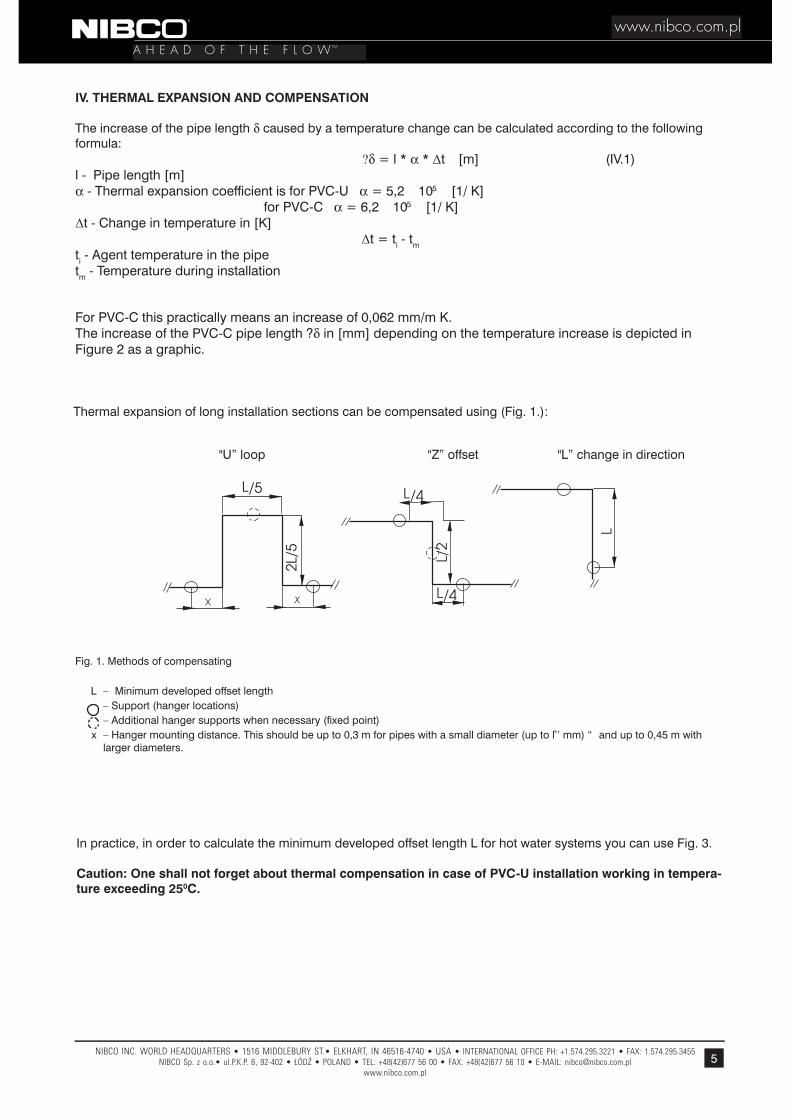
Fig. 1. Methods of compensating
L – Minimum developed offset length – Support (hanger locations) – Additional hanger supports when necessary (fixed point) x – Hanger mounting distance. This should be up to 0,3 m for pipes with a small diameter (up to ¾’’ mm) “ and up to 0,45 m with larger diameters.
IV. THERMAL EXPANSION AND COMPENSATION
The increase of the pipe length δ caused by a temperature change can be calculated according to the following formula: ?δ = l * α * ∆t [m] (IV.1) l - Pipe length [m]α - Thermal expansion coefficient is for PVC-U α = 5,2 � 10-5 [1/ K]
for PVC-C α = 6,2 � 10-5 [1/ K]∆t - Change in temperature in [K] ∆t = ti - tm ti - Agent temperature in the pipetm - Temperature during installation For PVC-C this practically means an increase of 0,062 mm/m K. The increase of the PVC-C pipe length ?δ in [mm] depending on the temperature increase is depicted in Figure 2 as a graphic.
"U” loop "Z” offset "L” change in direction
Thermal expansion of long installation sections can be compensated using (Fig. 1.):
In practice, in order to calculate the minimum developed offset length L for hot water systems you can use Fig. 3.
Caution: One shall not forget about thermal compensation in case of PVC-U installation working in tempera-ture exceeding 250C.

6
A H E A D O F T H E F L O W
www.nibco.com.plTM
Fig. 2. Expansion of PVC-C pipe vs. the temperature
len
gth
l

7
www.nibco.com.plA H E A D O F T H E F L O W TM
Fig. 3. Choosing the right type of compensation for PVC-C hot water systems (ti= 55oC, tm= 10oC)
16 20 25 32 40 50
Minimum developed offset length

8
A H E A D O F T H E F L O W
www.nibco.com.plTM
Fig. 4. Compensation for thermal expansions in vertical shafts
V. ASSEMBLING OF THE NIBCO PVC-U AND PVC-C SYSTEMS
The principles of assembling PVC-U and PVC-C installations are in no way different from principles of assembling steel pipe. Additional requirements are mainly due to the greater thermal expansion of the material used. One has to consider this expansion in the planning phase by using appropriate compensations (see Chapter IV).
When designing the water pipeline, one has to consider the given building conditions. In other words, one has “to utilize wall set-offs and bends for the natural compensation of thermal expansions and use any opportunity “to mount fixed points, when passing through walls and ceilings.It is also important to place and assemble the installation without any stresses if possible. This means that passages through the plaster and the mounting of hangers should be carried out preserving the necessary distance from points where the installation changes its direction. It is also necessary to preserve enough clearance when passing through walls.Different modes of compensation of thermal expansion for vertical rises shafts are shown on Fig.4a, 4b, 4c.
Fig. 5. Insulation of bends
There are some doubts about installing PVC-U and PVC-C systems in walls and under the plaster. In wall chases under “the plaster, the system can (but does not have to) be insulated with commonly used materials.
At points where “the pipeline changes its direction, fittings and the developed offset length should be insulated with elastic materials (for instance the THERMAFLEX, CLIMAFLEX and similar types of heat insulation), so that they do not restrict possible length changes. This is flexible insulation of bends (Fig. 5). One should make sure that the heat insulation used is compatible with PVC-U and PVC-C.
Installation in wall chases embedded in concrete or in concrete itself does not require any compensation, but “it is necessary to provide for a sufficient concrete layer (min. 2,5 cm for a ½”pipe). Compensation is neces-sary though, when the pipes are to be insulated, which is often the case when the installation is placed under the plaster on the wall. Pipeline routes embedded in concrete should be located in places where one is cer-tain the concrete layer will not crack.

9
www.nibco.com.plA H E A D O F T H E F L O W TM
It is easy to prove that the stress occurring due to a temperature change an installation in the wall is absorbed by PVC-C and that its value is much below the allowed limit. The following example shows “a temperature change of 55°C:
It is easy to prove that the stress occurring due to a temperature change an installation in the wall is absorbed by PVC-C and that its value is much below the allowed limit. The following example shows “a temperature change of 55°C:
Maximum extension: ε = ∆t * (α 1 - α 2)α1 - PVC-C thermal expansion coefficient - 6,2 � 10-5 -5 1/ Kα2 - wall the rmal expansion coefficient - 4,5 10-6 � 10-6 1/ Kε = 0,0032 mm/mm
Therefore, the PVC-C stress equals: σ = E * ε [MPa]σ = 2482 � 0,0032 = 7,9 MPaE - Young’s elasticity modulus
The permissible compressive stress for PVC-C equals 62 MPa, therefore the resulting stress of 7,9 Mpa is much lower than the maximum permissible value.
VI. PIPE SUPPORT
In order to ensure the proper functioning of pipe, they should be supported at specified distances as speci-fied below:
1/2” 1,10 1,05 0,90 3/4” 1,25 1,10 1,00 1” 1,45 1,25 1,10 1.1/4” 1,60 1,40 1,20 1.1/2” 1,65 1,60 1,35 2” 1,90 1,70 1,50 2.1/2” 2,20 1,90 1,65 3” 2,40 2,10 1,80 4” 2,80 2,40 2,10 6” 3,30 3,00 2,50 8” 3,60 3,45 3,00
Pipe diameter
SUPORT SPACING [m] (vertical pipe) PVC-U Sch
[inches]
Temperature [°C]
20 40 60
SUPORT SPACING [m] (vertical pipe) PVC-U wg. PN 15/12/9
Pipe diameter Temperature [°C]
[inches] 25 45
1/2” 0,85 0,80 3/4” 0,95 0,85 1” 1,10 1,00 1.1/4” 1,20 1,10 1.1/2” 1,30 1,20 2” 1,50 1,30 3” 1,90 1,60 4” 2,20 1,90
SUPORT SPACING [m] (vertical pipe) PVC-C Pipe
diameter[inches]
Temperature [°C]
SC
H 8
0 C
TS S
DR
11 1/2” 0,75 0,70 0,65 0,60 0,50
3/4” 0,85 0,80 0,70 0,65 0,55 1” 0,90 0,85 0,75 0,70 0,60 1.1/4” 1,00 0,95 0,85 0,75 0,65 1.1/2” 1,10 1,05 0,95 0,80 0,75 2” 1,25 1,15 1,05 0,90 0,80 2.1/2” 2,40 2,25 1,95 1,20 1,00 3” 2,40 2,40 2,10 1,20 1,05 4” 2,40 2,70 2,25 1,35 1,10
Metal hangers with compressible washers should be used only when necessary, for instance for fixed points “or mounting of instruments.
Caution: The above distances can be increased for vertically mounted pipe, by multiplying them by 1.3 for tem-peratures up to 60°C or by 1.2 for higher temperatures. When mounting instruments, batteries etc. on the pipe, one should ensure their proper support. Remember, that vertical pipe should have supports at every ceiling passing and when changing the direction by 90°. All supports ensure the proper installing of developed offset length.

10
A H E A D O F T H E F L O W
www.nibco.com.plTM
correctincorrect
Fig. 6. Incorrect and correct way of taking the developed offset length
In case of longer sections, it is possible to divide the expansion segments by the appropriate choice of fixed points which allow for their better compensation. Fixed installation points are created when mounting elements, mounting units, valves under the plaster, fittings, etc., are attached to walls.Figs. 7 and 8 show a way to mount fixed points:
Fig. 7. Fixed point on the pipe with use of halves of pipe (one dimension bigger)
Fig. 8. Fixed point installed near the fitting with use of the fitings

11
www.nibco.com.plA H E A D O F T H E F L O W TM
Fig. 9 shows the example of placing both sliding and fixed points in a multi-story building riser. Figure 10 shows the placement for horizontal distribution pipe.
X X
XX
X
X
PP PS
X
X
X
PS
PP
The sliding (movable) support should allow for an axial movement of the pipeline without greater resis-tance. At the same time, it should not damage the pipe’s surface.
PS - fixed pointPP - sliding (movable) support
Fig. 9. Placement of support spacing length of the offset length,
Fig. 10. Placement of support spacing on horizontal distribution pipe.
In some situations, due to the length in a building’s riser, hanging holders should be used. Such holders allow the pipe to move in all directions.

12
A H E A D O F T H E F L O W
www.nibco.com.plTM
VII. AIR CONDITIONING / COOLING IN NIBCO PVC FlowGuard Gold® SYSTEMS APPLICATIONS
In recent years, the installation of air conditioning systems in buildings with diversified uses has become more common. The ideal material that fulfills the requirements of such installations is the PVC-C FlowGuard Gold® system, which is suitable to transport both the heating agent and chilled water
During the designing and installation process, it is necessary to consider the thermal properties of pipe - their expansion when transporting a heating agent and their contraction when transporting chilled water. The appropriate thermal operation of the pipelines is achieved through changing the running direction of pipe - self-compensation, as well as using “U” loops. Appropriate pipeline supports - sliding supports and fixed points (with EPDM inserts) should be used.
If you want to use other media than water within air conditioning or cooling units, you should acquire an approval from NIBCO - every time you wish to do so.
One of the commonly used solutions for air conditioning cooling systems is ethylene glycol that allows for “a working temperature from -4°C to +70°C. This medium has been approved by NIBCO for use in PVC-C FlowGuard Gold® piping system up to 35% concentration.
There are numerous, well-known advantages of using the PVC-C FlowGuard Gold® system within air conditioning installations that are described in this paper. We can add here several years long presence of our system in the European market and now we have a great number of well trained installers and designers who guarantee a professional realization of a system.
Caution: To make the system cheaper one can apply PVC-U pipes to drain off condensate with temperature lower than 500C.
VIII. HEAT INSULATION OF PIPE
Insulation for pipes should meet local code requirements. Preferred insulation types include those based on foam, paperboard, aluminum foil and microporous rubber. “The insulation’s thermal conductivity must be at least 0,040 W/m K.
You should choose the thickness of the insulation in such a way that the temperature on the exterior insulation surface does not exceed Tz = ambient temp. + 4°C.
The insulation materials used must be compatible with PVC-C. If in doubt, please contact Product Department of NIBCO Sp. z o.o.
IX. INSTALLATION GUIDELINES
1. Installing pipe on plaster
When installing pipe on plaster, you should stick to the principles of compensating thermal expansion. Usually, it is possible to utilize natural arcs and bends resulting from the building’s geometry.
Since the pipe can be subject to external mechanical damage, they should be placed behind skirting boards. Another reason is the aesthetical aspect.
2. Placing pipe in partitions
Placing pipe in partitions can be subdivided into:– placing pipe in wall chases– placing pipe in shafts– placing pipe in floor layers
13
www.nibco.com.plA H E A D O F T H E F L O W TM
Due to thermal expansion, pipes for hot water installation systems have to be placed in a corrugated pipe, the so-called “Peschel” pipe or put in polyethylene foam, so that lengthwise movements are possible.
Passages through walls and ceilings have to be placed in an elastic sleeve that is one dimension bigger in diameter.
Pipe in floor layers definitely have to be placed in “Peschel” insulation pipe. The minimal filling compound thickness counted from the “Peschel” pipe surface should be 2,5 cm.
In installation shafts, it is necessary to pay special attention so that the pipeline can compensate changes of the vertical route length, which can be achieved by appropriately locating the vertical pipe or by setting changing in direction.
In case of double-tube riser both pipes must be placed parallel to each other and the distance between their axes should be constant - 80 mm - when diameter of a pipe does not exceed 40 mm. The acceptable deviation amounts to +/- 5 mm.
Horizontal pipelines in cellars are to be placed below the ceiling or in floor ditches with a slope of at least 5‰ to assure drainage of system.
3. Mounting of the pipe
The pipe should be mounted in such a way that they are firmly attached to the building structure, allowing at the same time for unconstrained lengthwise movements.
Fixed points have to be mounted in places that allow for pipe thermal compensation. As a principle, you should use the fittings to block the lengthwise movement of the pipe at the fixed point. Horizontal pipelines placed near walls, in lofts or in wall chasings should rest on fixed or sliding supports. Their placement should be included in the project. At fixed supports of the pipe, compressible washers (made of EPDM) should be placed between the pipe and the clamp. Wherever the pipe is exposed to mechanical blows, it should be placed in protecting pipe.
4. Protecting heating units
All hot water sources used for hot water (boilers, stoves, etc.) that are to supply the PVC-C installation system should be equipped on their output with a working thermostatic device eliminating the possibility of water entering the installation with a temperature that exceeds the acceptable limit, that is 80°C.
In the case of hanging stoves, the installation should be connected by means of metal connector pipe with a length of minimum “25 cm in order to protect it against the heating source directly heating the pipes. In the case of standing stoves, we advise the use of metal pipe with a length of minimum 1m (this especially applies to devices with outer surfaces that can reach high temperatures). In case of wood-fired or coal-fired boilers PVC-C systems should not be applied.
The possibility of using NIBCO PVC-C pipe for hot water systems together with flow heaters, both gas and electric, depends upon the manufacturer of these heaters. The manufacturer also establishes the way of connecting the pipe to the heater (inlet and outlet).
5. System tightness tests.Should be carried out according local building or plumbing code.Caution!Constant temperature must be maintained throughout the whole tests, since pressure in the system may be influenced by temperature changes.
All leak tightness tests should be conducted before covering the wall chasings and channels and before applying thermal insulation.

14
A H E A D O F T H E F L O W
www.nibco.com.plTM
FINAL REMARKS
The system durability and quality depend on the type of the material used in its construction and the joining method. The correct functioning of a modern system is also essentially influenced by the automatic control system responsible for the working parameters, along with the quality of the building elements of that automation. “A defected or malfunctioning temperature regulating device can significantly lower the system’s life.
The PVC-C pipe system is characterized by an excellent material quality and an exceptionally easy and fast installation that does not require any special equipment or tools. There is no need for maintenance, and it is aesthetically pleasing.
X. STORAGE
PVC-C pipe and pipe fittings can be stored both inside and outside the building, for instance at the building construction site. When storing them in the open air, they should not be exposed to the sun. The pipe should not be tightly covered, though, since an unrestrained airflow is important in order to decrease the temperature on hot, sunny days.
In addition, the pipe should be stored in such a way that they are not bent or exposed to mechanical damage (squeezing, abrasing).Therefore, plastic pipe should not be stored together with metal pipe. The layers should be protected against movement. Pipe with a greater diameter should be placed on the bottom. If the number of the stored pipe layers is too big, pipe placed at the bottom can deform at higher temperatures.
One should remember that both PVC-U and PVC-C pipes stored at temperatures below 0°C become brittle. Dropping them may also cause cracks. Within buildings, the pipe should be placed on stands. If possible, they should be supported on the whole pipe length (they are manufactured as 3m, 6m pipe). If this is not possible, then the distance between the supporting elements should not exceed 1m (the width of the supporting elements itself should be at least 8cm).Fittings should be stored in original cardboard boxes or bags, protecting them against dirt and damage (if possible, they should be stored inside the building).Proper storage of pipe and fittings decreases the probability of problems occurring during the installation process.
Before joining any pipe or fittings together, you should check for mechanical damage.“
6. Flushing and disinfection of pipes.If leak tightness test is successful, the pipe must be flushed by fresh water from water supply system.
The speed of water in the pipe should be big enough to remove of all mechanical impurities.
After the flushing, the flushing water should be subjected to physical and chemical and bacteriological examinations in an authorized research unit.
Flushing and disinfection should be carried out according local building or plumbing code.
15
www.nibco.com.plA H E A D O F T H E F L O W TM
1. 2. 3.
4. 5. 6.
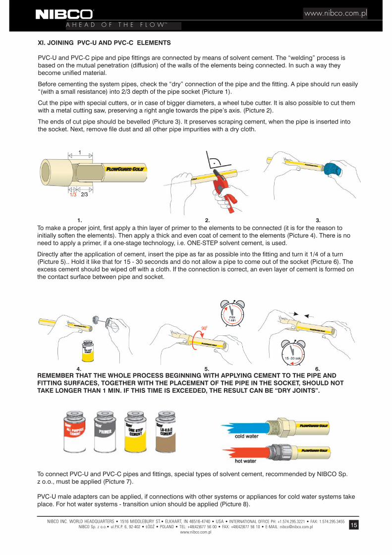
XI. JOINING PVC-U AND PVC-C ELEMENTS
PVC-U and PVC-C pipe and pipe fittings are connected by means of solvent cement. The “welding” process is based on the mutual penetration (diffusion) of the walls of the elements being connected. In such a way they become unified material.
Before cementing the system pipes, check the “dry” connection of the pipe and the fitting. A pipe should run easily “(with a small resistance) into 2/3 depth of the pipe socket (Picture 1).
Cut the pipe with special cutters, or in case of bigger diameters, a wheel tube cutter. It is also possible to cut them with a metal cutting saw, preserving a right angle towards the pipe’s axis. (Picture 2).
The ends of cut pipe should be bevelled (Picture 3). It preserves scraping cement, when the pipe is inserted into the socket. Next, remove file dust and all other pipe impurities with a dry cloth.
To make a proper joint, first apply a thin layer of primer to the elements to be connected (it is for the reason to initially soften the elements). Then apply a thick and even coat of cement to the elements (Picture 4). There is no need to apply a primer, if a one-stage technology, i.e. ONE-STEP solvent cement, is used.
Directly after the application of cement, insert the pipe as far as possible into the fitting and turn it 1/4 of a turn (Picture 5).. Hold it like that for 15 - 30 seconds and do not allow a pipe to come out of the socket (Picture 6). The excess cement should be wiped off with a cloth. If the connection is correct, an even layer of cement is formed on the contact surface between pipe and socket.
REMEMBER THAT THE WHOLE PROCESS BEGINNING WITH APPLYING CEMENT TO THE PIPE AND FITTING SURFACES, TOGETHER WITH THE PLACEMENT OF THE PIPE IN THE SOCKET, SHOULD NOT TAKE LONGER THAN 1 MIN. IF THIS TIME IS EXCEEDED, THE RESULT CAN BE “DRY JOINTS”.
To connect PVC-U and PVC-C pipes and fittings, special types of solvent cement, recommended by NIBCO Sp. z o.o., must be applied (Picture 7).
PVC-U male adapters can be applied, if connections with other systems or appliances for cold water systems take place. For hot water systems - transition union should be applied (Picture 8).

16
A H E A D O F T H E F L O W
www.nibco.com.plTM
Table 4.Number of joints made with one solvent cement can with a capacity of 0,118 l
Pipe with diameters above 40mm should be connected by two people.
If the cementing process was performed correctly, a “bead” should be visible around the fitting on the pipe.
The curing time for solvent cemented joints depends both on the ambient temperature and the diameter of the ele-ments being connected. Here is areference for using standard 1-step cement.
Temp. 15 - 40°C a) For pipes up to 32 mm 1 hour* b) For pipes 40 - 50 mm 2 hours* c) For pipes 100 - 200 mm 6 hours*
Temp. 5 - 15°C a) For pipes up to 32 mm 2 hours* b) For pipes 40 - 50 mm 4 hours* c) For pipes 100 - 200 mm 12 hours*
Temp. -20°C - +5°C a) For pipes up to 32 mm 8 hours* b) For pipes 40 - 50 mm 16 hours* c) For pipes 100 - 200 mm 48 hours*
* After this time, you can check the installation under a pressure of 1,05 MPa.
In the case of high air humidity >60%, the time after which you can check the installation must be increased “by 50%.
Caution:1. Solvent cements are inflammable. Keep away from fire!2. Temperature for storing cements 5°C - 45°C.3. Keep cans with cements tightly sealed.4. Avoid inhaling solvent fumes. If you are working indoors, ensure proper ventilation.5. Avoid direct contact of the cement and skin.
Table 4 shows the efficiency of a typical cement can.
1/2” (16 mm) 75 82 3/4” (20 mm) 50 55 1” (25 mm) 31 34 1 1/4” (32 mm) 30 33 1 1/2” (40 mm) 21 23 2” (50 mm) 15 17 2 1/2” (62 mm) 11 11 3” (75 mm) 10 10 4” (100 mm) 7 7 6” (150 mm) 2 - 8” (200 mm) 1 -
Pipe, fitting dimension PVC-U PVC-C

17
www.nibco.com.plA H E A D O F T H E F L O W TM
XII. INSTALLATION & SERVICE TIPS
♦ In practice, the measured values of thermal expansions are much lower compared to the calculations. The installation’s connection system, direction changes as well as the pipe elasticity take on the changes in length resulting from changes in temperature.
Therefore it is sufficient for PVC-C pipes used for hot water systems to use offset of 30 cm every 3 m.
The problems regarding the compensation of thermal expansions have been discussed in detail in Chapter IV.
♦ Any heating devices to which the PVC-C system is connected should be equipped with thermostatic protection“ against overheating. The system should be connected through metal pipes of 25 cm in length, both on the hot water and the cold water supply side (this is especially true for devices, which outside surfaces can reach high temperatures).
♦ Due to the low thermal conductivity of PVC-U and PVC-C, the pipes do not “sweat”. There is no need to insulate cold and hot water pipes inside the building. This phenomenon can only be observed in rooms with very high air humidity and temperature (baths, showers, laundries etc.).
♦ It is recommended to test the system under a pressure of 1,05 MPa for at least one hour. In warm weather conditions you can start the test 60 minutes after makeing the last joint (see page 14). Remember that the test pressure cannot exceed the maximum pressure of the individual system elements.
♦ It is recommended to test the system under a pressure of 1,05 MPa for at least one hour. In warm weather conditions you can start the test 60 minutes after performing the last joint. Remember that the test pressure cannot exceed the maximum pressure of the individual system elements.
♦ Remember, in case of installations under the plaster, the system’s pressure test must be performed before putting the plaster on.
♦ It is advisable to use insulation foam when the installation direction changes and when the installation leaves the plaster. Insulation foam allows for some movements resulting from pipe expansion. In places where there i s a great probability of stress occurring (taps, shower heads) it is advisable to use - for connecting - transition unions.
♦ In order to seal threaded PVC-U or PVC-C fittings, use high density teflon tape with a thickness of min. 0,1 mm. It is possible that tightening up the joint “finger tight” is sufficient. Further tightening up the joint by using a strap wrench is allowed if you proceed with utmost care and do not perform more than 1,5 - 2 turns.
♦ Using appropriate adapter fittings and transition unions allow connections between metal and plastics.
♦ Since the thread in a PCV-U female adapter is tapered one (catalogue No 435-), one must be careful to connect it with a male metal thread.
♦ Old or expired solvent cement changes its color and takes on the consistency of a jelly. Do not use such “glue” under any circumstances. Do not use solvents to thin down the glue. Check the date of the solvent cement on the can for expiration date.
♦ It is best to cut the pipe with special cutters. You can also use household methods (metal cutting saw), but you have to carefully clean the elements to be connected before applying the solvent cement.
Use compressible washers at fixed pipe mounting points between the pipe and the hanger. Before using them make sure that the washer material is compatible with PVC-U and PVC-C. In places where pipe passes through walls and ceilings, it is advisable to use insulation foam slevees.
♦ DO NOT ALLOW WATER TO FREEZE IN PVC-C PIPES. In case of water freezing within the pipe, the pipe should be warmed up with warm air and then insulated to protect it against renewed freezing. If necessary, the pipe can also be cut and a pump pumping warm water can be connected. Do not use open flames!

18
A H E A D O F T H E F L O W
www.nibco.com.plTM
Fig. 11
When the pipe leaks at a fitting, the safest method is to cut out the fitting along with the pipe pieces. Then insert a new fitting with two couplings (Fig. 12).
cut the damaged piece
put the ends together with help of a single coupling
if the ends cannot be put together, use a piece
of new pipe,together with two couplings
XIII. IN-GROUND INSTALLATIONS
Outside of buildings, plastic pipe is placed in trenches. The bottom of the trench should be even and free from stones. If there are any boulders or stones, they have to be covered with a layer of sand or removed. The trench should be broad enough to make connection works possible and the “snakelike” placement of pipe to protect them against the influence of temperature (when you connect pipe outside the trench, the trench does not have to be as broad).
The depth of the trench depends on the freezing depth. Plastic pipe should definitely be placed below the freezing depth, with no exceptions. Pipe carrying liquids sensitive to freezing should be installed no less than 30 cm below the freezing depth.
Finished installations should be covered with backfill. The backfill’s granulation should be 12 mm. If you cover the trench with sand or gravel, do so by shaking the backfill over the pipes and trench. When using sand or gravel with a large admixture of clay or loam, it should be done by hand or other mechanical means. The trench should be covered in layers.
In order to be able to easier localize the pipeline’s route in the future, it is advisable to use metal wire around the plastic pipe.
XIV. REPAIRING PVC-C PIPE
If the pipe leaks, you have to cut out the damaged piece. If both pipe ends can be put together, they should be solvent cements together with a single pipe coupling. If this is impossible, it is necessary to use a new pipe with two couplings (Fig. 11).

19
www.nibco.com.plA H E A D O F T H E F L O W TM
cut out the leaking elbow
Fig. 12
and glue the new elbow including pipe piece with pipe and couplings
XV. CONCLUDING INSTALLATION REMARKS
The system’s durability and quality depends on several factors including the type of material used in its construc-tion and the joining technique. The correct functioning of a new system is also essentially influenced by the automatic control system responsible for the working parameters, along with the quality of the building elements that control those systems. Even cold water systems that have been equipped with minimal automatic controls require some form of pressure reduction for today’s modern systems, as well as a device to prevent water hammer (as mentioned in Chap. IV.1).
Hot water installations without a properly working automatic control should not be attempted at all. A defective “or malfunctioning temperature regulating device, that is not capable of keeping the temperature at the required level, could allow the temperature to rise beyond the safety limits of the system. In doing so, it significantly and unnecessarily lowers the system’s durability and life. Such broken temperature-regulating devices can also lead to scalding and burns by the water used in the system.
The above-mentioned elements of a system should be connected with controls in the heat distribution centers or boiler room that supply hot water systems.

20
A H E A D O F T H E F L O W
www.nibco.com.plTM