poro-serrated trailing edge devices for airfoil self-noise...
TRANSCRIPT
1
Poro-Serrated trailing edge devices for airfoil self-noise
reduction
Alexandros. Vathylakis1 and Tze Pei. Chong
2
Brunel University London, Uxbridge, England UB8 3PH, United Kingdom
and
Phillip F. Joseph3
ISVR, University of Southampton, Southampton, England SO17 1BJ, United Kingdom
This paper represents the continuation of the works previously published in Chong et al.
(“Self-Noise Produced by an Airfoil with Nonflat Plate Trailing-Edge Serrations,” AIAA
Journal, Vol. 51, No. 11, 2013, pp. 2665–2677), who used several nonflat plate serrated
trailing edges for the reduction of airfoil self-noise. The poro-serrated concept developed in
the current work improves substantially the overall noise performance of the nonflat plate
trailing-edge serration type. The use of porous metal, synthetic foams, or thin brush bundles
to fill the gaps between adjacent members of the sawtooth can completely suppress the
bluntness-induced vortex shedding tonal noise. Most important, up to 7 dB turbulent
boundary layer–trailing-edge broadband noise reduction can simultaneously be achieved
without compromising the aerodynamic performances in lift and drag. The poro-serrated
trailing edges do not cause any noise increase throughout the frequency range investigated
here. The reduction of the turbulent broadband noise is primarily caused by the serration
effect, but under a condition that the sawtooth surface must be solid and nonporous. The
primary role of the porous metal foams in a poro-serrated trailing edge is to suppress the
vortex shedding tonal noise. However, an optimum selection of the porous material is also
found to be able to further reduce the broadband noise level. The new serrated trailing-edge
concept developed here has the potential to improve the industrial worthiness of the
serration technology in achieving low noise radiation in fan and turbine blades.
1Research Assistant, College of Engineering, Design and Physical Sciences; [email protected]. Non-AIAA
member. 2(CORRESPONDING AUTHOR) Senior Lecturer, College of Engineering, Design and Physical Sciences;
[email protected]. Member AIAA 3Professor, Institute of Sound and Vibration Research; [email protected]. Member AIAA.
2
Nomenclature
2h = serration length (root-to-tip distance), mm
C = airfoil chord length, m
f = frequency, Hz
U = mean flow velocity, ms-1
x = streamwise direction measuring from the airfoil leading edge, mm
y = wall-normal direction, mm
z = spanwise direction, mm
= angle of attack for the airfoil, deg
= difference in measured by the surface-mounted hot-film sensor between a straight and a poro-serrated
trailing edge, dB
SPL = difference in sound pressure level between a baseline (straight) and a treated trailing edge, dB
= bluntness of saw tooth trailing edge at the root region, mm
= serration period, mm
= polar angles of the microphone relative to the jet flow centerline, deg
= power spectral density measured by surface-mounted hot-film sensor, dB
= mean square fluctuating velocity, (ms-1
)2/Hz
= overall wake power spectral density of the streamwise velocity, dB
φ = serration angle, deg
I. Introduction
N the middle of the last century, jet engine noise was considered to be the major source of aircraft noise. Since
then, the introduction of high bypass ratio turbofan engines has meant that jet noise is now considerably reduced.
Jet noise is now just one of numerous other comparable noise sources, all of which must be tackled in order to
reduce the overall aero engine noise. Important noise sources on modern aeroplane are generated at the trailing edge
of fan blades or the airframe’s high lift devices. The noise mechanism here is by the scattering of the hydrodynamic
I
3
pressure fluctuations near the trailing edge. At high Reynolds numbers, the boundary layer develops over the airfoil
surface is primarily turbulent and hence the radiated noise from the trailing edge is largely broadband in nature.
There has been much interest recently in developing methods aimed at reducing trailing edge broadband noise,
such as serrated edges [1-3], porous surfaces [4] and brushes [5-6]. These passive methods have been demonstrated
experimentally in low speed rig tests to afford levels of radiated noise reduction of roughly between 2 dB and 6 dB.
Serrated trailing edges, in particular, have been shown to highly effective in reducing noise. In nearly all cases,
however, the serrations have been formed from flat plates, which are then inserted into the trailing edge of the main
airfoil body. This was done for ease of manufacture and, more importantly, to prevent vortex shedding arising from
bluntness caused by cutting the serrations into the airfoil main body. Serrated flat plate inserts are unlikely to have
the structural integrity for continuously operation at high loading. Moreover, introducing flat plate inserts alter the
airfoil geometry and hence the global circulation around the airfoil is likely to degrade its aerodynamic performance
of the original airfoil.
More preferable from the point of view of structural integrity is to cut the serration patterns directly into the
airfoil body. However, whilst this configuration has also been shown to afford good level of broadband noise
reduction [7], the overall noise reduction is compromised by high level of bluntness-induced narrowband vortex
shedding noise. It is also envisaged that the airfoil’s pressure drag will increase due to the vortex shedding in the
wake. Previous attempt at reducing the bluntness-induced vortex shedding by wrapping woven-wire mesh screen
around the nonflat plate serrated trailing edge was only partially successful [8]. The reason might be due to the low
flow resistance of the mesh screen to be effective in suppressing the vortex shedding. Moreover, noise level is found
to increase at high frequency due to the surface roughness introduced by the mesh screen to the sawtooth surface. As
a result, the overall noise performance is not improved much.
A new approach to introducing serrations directly into the main body of airfoil is investigated in this paper which
will be shown to achieve good levels of broadband noise reduction whilst completely suppressing vortex shedding
noise at the blunt part of the serration. Central to the noise reduction strategy is the use of porous foams located
between adjacent members of sawtooth to fill the gap. Note that these porous foams were cut precisely to match the
exact shape of the interstices (sawtooth gaps), so that an original NACA0012 profile throughout the chord length is
preserved. The flow resistance associated with the porous foam arising from loss within the foam will be shown to
inhibit vortex shedding provided that the flow resistance is within some optimal range of values. If the flow
4
resistance of the porous foam is too high, scattering at the edge of the serration is modified to the extent that the
benefits of the serrations are diminished. In this work, the investigation is mostly focused on the use of porous metal
foam – nickel-chromium foam of moderate flow resistivity which has been found to almost completely suppress
vortex shedding while maintaining the benefits of the serrated trailing edge. At the same time, broadband noise
reduction can simultaneously be achieved without significant loss of efficiency. The combination of porous material
and serration at the trailing edge, which in this paper is termed as Poro-Serrated, now provides two possible noise
reduction mechanisms. One associated with the oblique edges due to the serrations, and the other arising from
porosity which allows the pressure and suctions sides to ‘communicate’, therefore reducing the acoustic dipole
strength at the trailing edge. Which of these is the dominant noise reduction mechanism will be discussed later in
this paper.
II. Experimental Setup
A. Test Model and the Trailing Edge Serrations
Similar to the previous work by the authors in [7, 8], the airfoil under investigation is a NACA0012 airfoil with a
sawtooth serration cut directly into the main body of the airfoil. The chord length (C) of the airfoil is 150 mm, and
the width is 450 mm. Between the leading edge x/C = 0, and x/C = 0.79, the original NACA0012 airfoil profile is
unmodified, where x is the streamwise direction. Further downstream, 0.79 < x/C < 1.0, is a section that can be
removed and replaced by a serration profile. Once attached the serrations form a continuous profile giving the
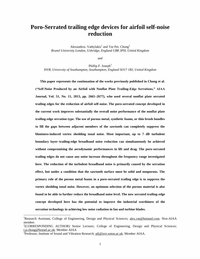
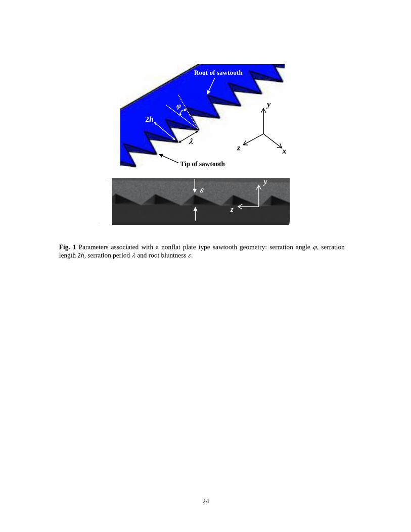
appearance that the serrations are cut into the main body of the NACA0012 airfoil. Figure 1 shows the parameters
associated with serrated trailing edge geometry. A prominent feature of this type of serrated trailing edge is the
exposure of a significant bluntness () at the root region, which would otherwise be negligible for the conventional
flat plate type serrated trailing edge.
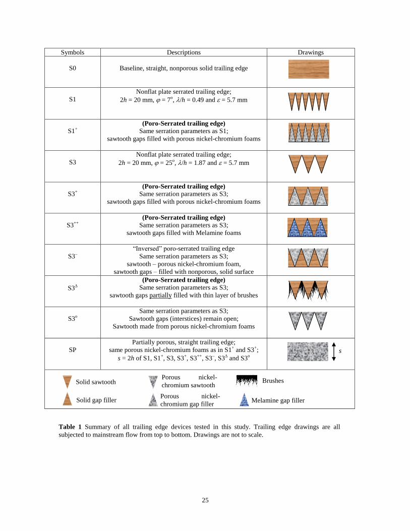
A total of ten trailing edge sections, including one with straight trailing edge to serve as the baseline case, were
investigated in this study. Table 1 summarizes the geometrical parameters and drawings of these trailing edge
sections. In particular, the poro-serrated trailing edges S1+, S3
+, S3
++ and S3
represent the core of investigation in
this paper. Note that between the (S1, S1+) group and (S3, S3
+, S3
++, S3
–, S3
and S3
o) group, they share the same
5
2h and values but with different values of and /h (see Table 1). The S1–group of serrations therefore has a
narrower sawtooth angle compared to the S3–group of serrations.
In this paper, the investigation of the poro-serrated trailing edge mainly focuses on the use of porous nickel-
chromium foam at the interstices. The porous nickel-chromium foam has the following characteristics: 17–23
pores/inch, pore diameter 0.9 mm, and air flow resistivity 8 kPa s/m2 (taken from data sheet). In addition,
brushes and Melamine foam were also attempted at the interstices (S3 and S3
++, respectively) to explore whether
the aeroacoustic performance of the poro-serrated trailing edge could be further enhanced by different porous
materials. The Melamine foam has good sound absorption property with 180 pores/inch and air flow resistivity
10 kPa s/m2 (taken from data sheet). The “inversed” poro-serrated trailing edges of S3
–, and other trailing edge
designs S3o and SP, also utilize porous nickel-chromium foams. Further details can be found in Table 1.
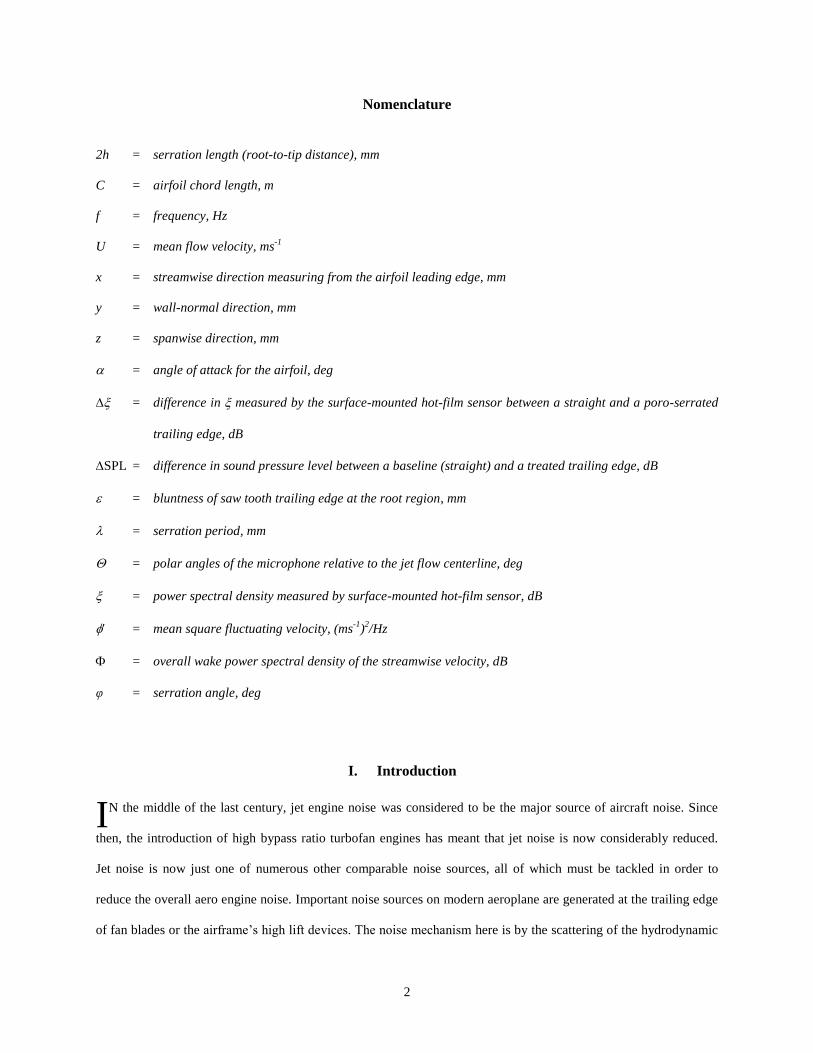
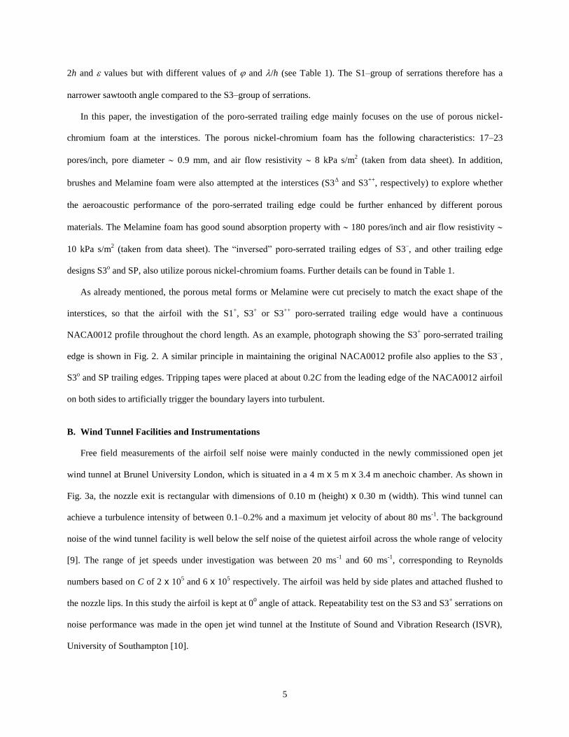
As already mentioned, the porous metal forms or Melamine were cut precisely to match the exact shape of the
interstices, so that the airfoil with the S1+, S3
+ or S3
++ poro-serrated trailing edge would have a continuous
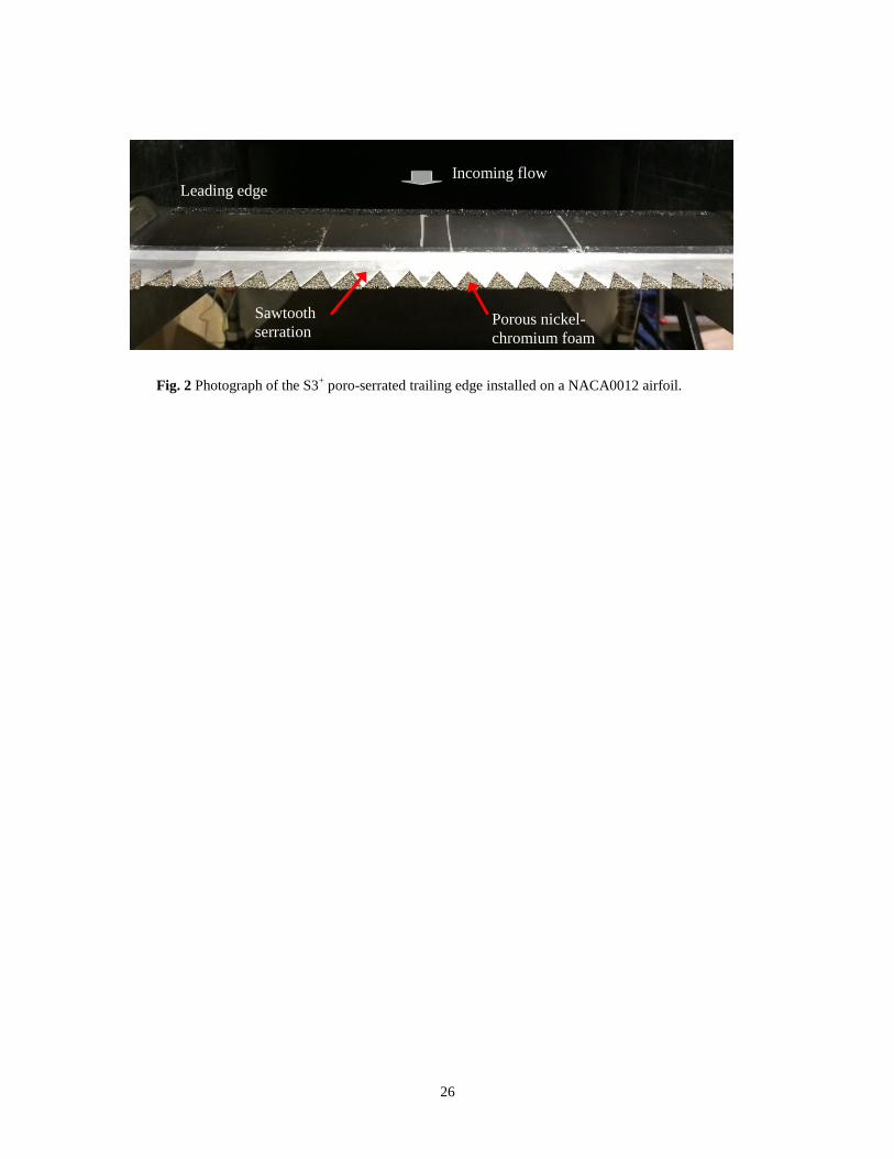
NACA0012 profile throughout the chord length. As an example, photograph showing the S3+ poro-serrated trailing
edge is shown in Fig. 2. A similar principle in maintaining the original NACA0012 profile also applies to the S3–,
S3o and SP trailing edges. Tripping tapes were placed at about 0.2C from the leading edge of the NACA0012 airfoil
on both sides to artificially trigger the boundary layers into turbulent.
B. Wind Tunnel Facilities and Instrumentations
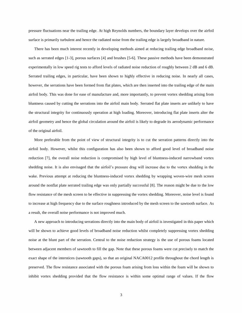
Free field measurements of the airfoil self noise were mainly conducted in the newly commissioned open jet
wind tunnel at Brunel University London, which is situated in a 4 m x 5 m x 3.4 m anechoic chamber. As shown in
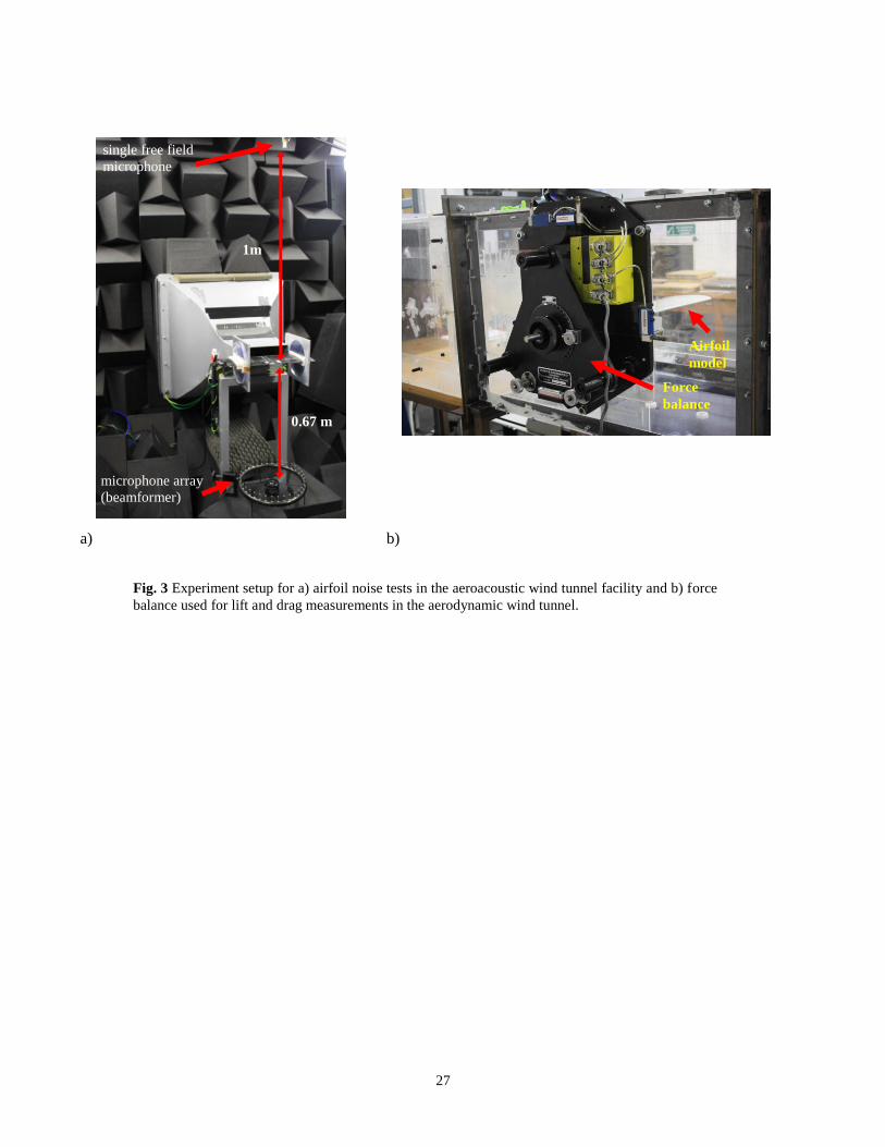
Fig. 3a, the nozzle exit is rectangular with dimensions of 0.10 m (height) x 0.30 m (width). This wind tunnel can
achieve a turbulence intensity of between 0.1–0.2% and a maximum jet velocity of about 80 ms-1
. The background
noise of the wind tunnel facility is well below the self noise of the quietest airfoil across the whole range of velocity
[9]. The range of jet speeds under investigation was between 20 ms-1
and 60 ms-1
, corresponding to Reynolds
numbers based on C of 2 x 10⁵ and 6 x 10
5 respectively. The airfoil was held by side plates and attached flushed to
the nozzle lips. In this study the airfoil is kept at 0o angle of attack. Repeatability test on the S3 and S3
+ serrations on
noise performance was made in the open jet wind tunnel at the Institute of Sound and Vibration Research (ISVR),
University of Southampton [10].
6
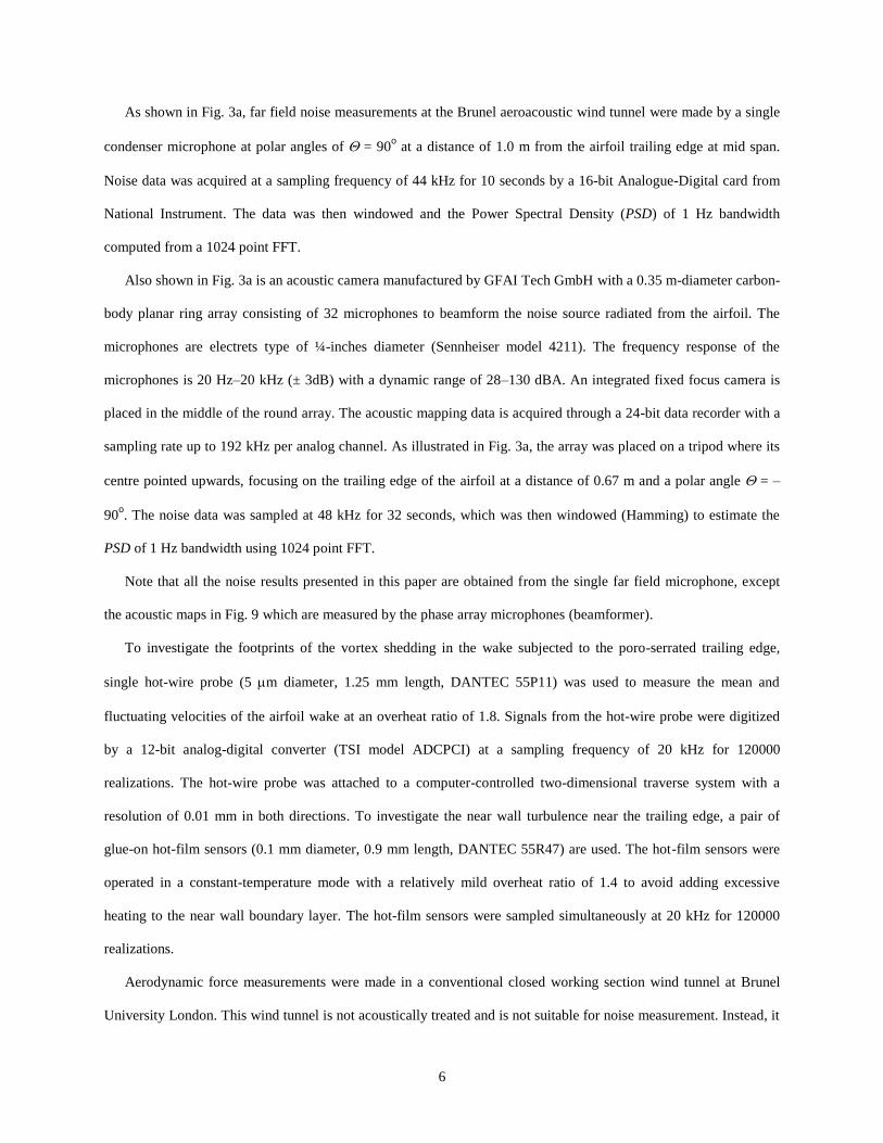
As shown in Fig. 3a, far field noise measurements at the Brunel aeroacoustic wind tunnel were made by a single
condenser microphone at polar angles of = 90o at a distance of 1.0 m from the airfoil trailing edge at mid span.
Noise data was acquired at a sampling frequency of 44 kHz for 10 seconds by a 16-bit Analogue-Digital card from
National Instrument. The data was then windowed and the Power Spectral Density (PSD) of 1 Hz bandwidth
computed from a 1024 point FFT.
Also shown in Fig. 3a is an acoustic camera manufactured by GFAI Tech GmbH with a 0.35 m-diameter carbon-
body planar ring array consisting of 32 microphones to beamform the noise source radiated from the airfoil. The
microphones are electrets type of ¼-inches diameter (Sennheiser model 4211). The frequency response of the
microphones is 20 Hz–20 kHz (± 3dB) with a dynamic range of 28–130 dBA. An integrated fixed focus camera is
placed in the middle of the round array. The acoustic mapping data is acquired through a 24-bit data recorder with a
sampling rate up to 192 kHz per analog channel. As illustrated in Fig. 3a, the array was placed on a tripod where its
centre pointed upwards, focusing on the trailing edge of the airfoil at a distance of 0.67 m and a polar angle = –
90o. The noise data was sampled at 48 kHz for 32 seconds, which was then windowed (Hamming) to estimate the
PSD of 1 Hz bandwidth using 1024 point FFT.
Note that all the noise results presented in this paper are obtained from the single far field microphone, except
the acoustic maps in Fig. 9 which are measured by the phase array microphones (beamformer).
To investigate the footprints of the vortex shedding in the wake subjected to the poro-serrated trailing edge,
single hot-wire probe (5 m diameter, 1.25 mm length, DANTEC 55P11) was used to measure the mean and
fluctuating velocities of the airfoil wake at an overheat ratio of 1.8. Signals from the hot-wire probe were digitized
by a 12-bit analog-digital converter (TSI model ADCPCI) at a sampling frequency of 20 kHz for 120000
realizations. The hot-wire probe was attached to a computer-controlled two-dimensional traverse system with a
resolution of 0.01 mm in both directions. To investigate the near wall turbulence near the trailing edge, a pair of
glue-on hot-film sensors (0.1 mm diameter, 0.9 mm length, DANTEC 55R47) are used. The hot-film sensors were
operated in a constant-temperature mode with a relatively mild overheat ratio of 1.4 to avoid adding excessive
heating to the near wall boundary layer. The hot-film sensors were sampled simultaneously at 20 kHz for 120000
realizations.
Aerodynamic force measurements were made in a conventional closed working section wind tunnel at Brunel
University London. This wind tunnel is not acoustically treated and is not suitable for noise measurement. Instead, it
7
is only used for measurements of the lift and drag forces produced by the NACA0012 airfoil with poro-serrated
trailing edges. The wind tunnel has a test section of 0.5 m x 0.5 m, a maximum velocity in the test section of about
38 ms-1
and a freestream turbulence intensity of about 0.2–0.3%. The airfoil model was mounted horizontally across
almost the entire width of the test section (1 mm gap on each side of the wind tunnel side window). In order to
investigate the effect of the poro-serration on the aerodynamic forces, a 3-component strain gauge force balance was
used to measure the lift and drag forces produced by the airfoil. As shown in Fig. 3b, it consists of a mounting plate,
which is used to secure the device to the wind tunnel side window, and a triangular force plate. The force plate and
the mounting plate were connected via three spherical universal joints constraining the motion of the force plate
parallel to the direction of the mounting plate. Forces incurred by the airfoil were transmitted to three strain gauges
via the cables. The angle of attack of the airfoil was rotated via a disc between 0o to 20
o.
III. Noise Results
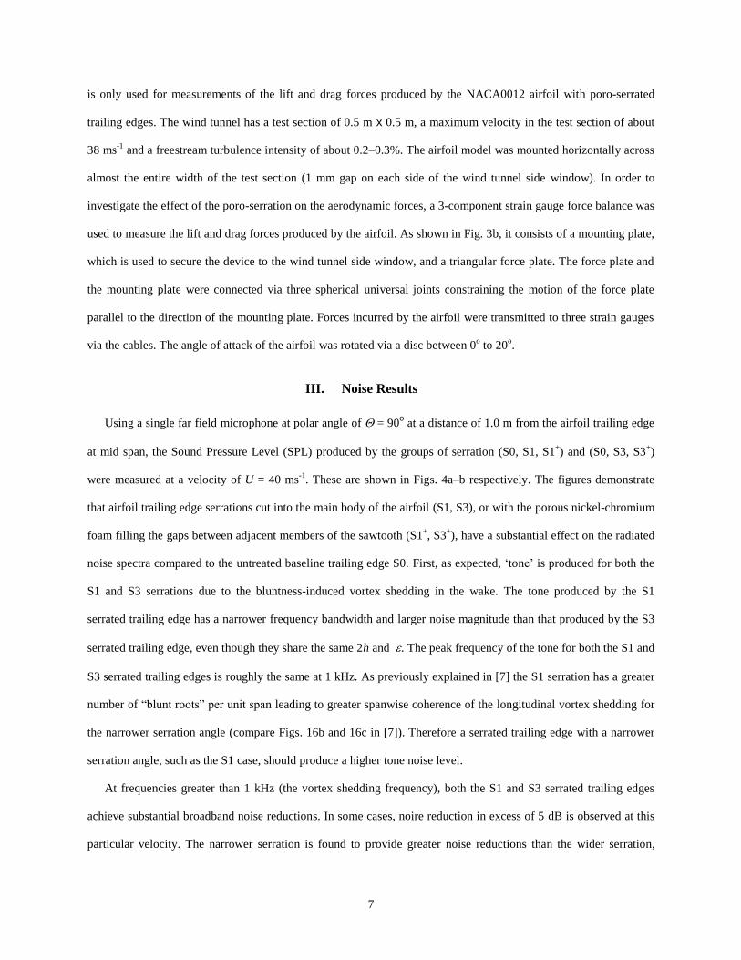
Using a single far field microphone at polar angle of = 90o at a distance of 1.0 m from the airfoil trailing edge
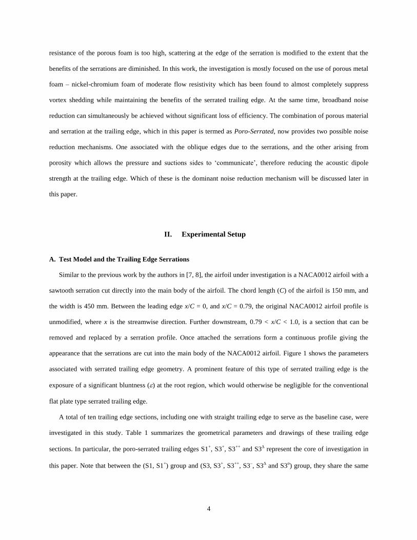
at mid span, the Sound Pressure Level (SPL) produced by the groups of serration (S0, S1, S1+) and (S0, S3, S3
+)
were measured at a velocity of U = 40 ms-1
. These are shown in Figs. 4a–b respectively. The figures demonstrate
that airfoil trailing edge serrations cut into the main body of the airfoil (S1, S3), or with the porous nickel-chromium
foam filling the gaps between adjacent members of the sawtooth (S1+, S3
+), have a substantial effect on the radiated
noise spectra compared to the untreated baseline trailing edge S0. First, as expected, ‘tone’ is produced for both the
S1 and S3 serrations due to the bluntness-induced vortex shedding in the wake. The tone produced by the S1
serrated trailing edge has a narrower frequency bandwidth and larger noise magnitude than that produced by the S3
serrated trailing edge, even though they share the same 2h and . The peak frequency of the tone for both the S1 and
S3 serrated trailing edges is roughly the same at 1 kHz. As previously explained in [7] the S1 serration has a greater
number of “blunt roots” per unit span leading to greater spanwise coherence of the longitudinal vortex shedding for
the narrower serration angle (compare Figs. 16b and 16c in [7]). Therefore a serrated trailing edge with a narrower
serration angle, such as the S1 case, should produce a higher tone noise level.
At frequencies greater than 1 kHz (the vortex shedding frequency), both the S1 and S3 serrated trailing edges
achieve substantial broadband noise reductions. In some cases, noire reduction in excess of 5 dB is observed at this
particular velocity. The narrower serration is found to provide greater noise reductions than the wider serration,
8
consistent with the theoretical predictions of Howe [11]. In conclusion, therefore, a serration cut into the main body
of an airfoil with a narrower serration angle provides better broadband noise reduction, but more intense tonal vortex
shedding noise.
With porous nickel-chromium foam now introduced between adjacent teeth, both S1+ and S3
+ porous-serrations
not only completely suppress the bluntness-induced vortex shedding tonal noise, but also provide a consistently
lower noise level compared to the baseline straight trailing edge S0. Comparing the poro-serrated trailing edge S1+
with its S1 counterpart reveals similar levels of broadband noise reduction at frequencies, f, greater than about 1.7
kHz. In addition, the spectral shapes follow a similar frequency oscillation pattern at f > 1.7 kHz. The same
observation applies to the S3+ and S3 trailing edges, where similar levels of broadband noise reduction are observed
at f > 1.85 kHz and both follow the same spectral shape.
Another advantage of introducing porous metal foam in the gaps between adjacent teeth is that high frequency
noise increases, as observed by Gruber et al. [12] with the use of conventional flat plate type serrated trailing edge,
is avoided. They attributed this noise increase to the presence of cross-jet through the gaps between adjacent teeth.
However, with the introduction of metal foam now filling this gap, this mechanism is now avoided and no
significant increase in noise is observed over the frequency range of interest up to 20 kHz.
The following sections will discuss more thoroughly the impact of introducing the (S1+, S3
+) poro-serrated
trailing edges to the airfoil self noise reduction.
A. Suppression of the Bluntness-Induced Vortex Shedding Tonal Noise
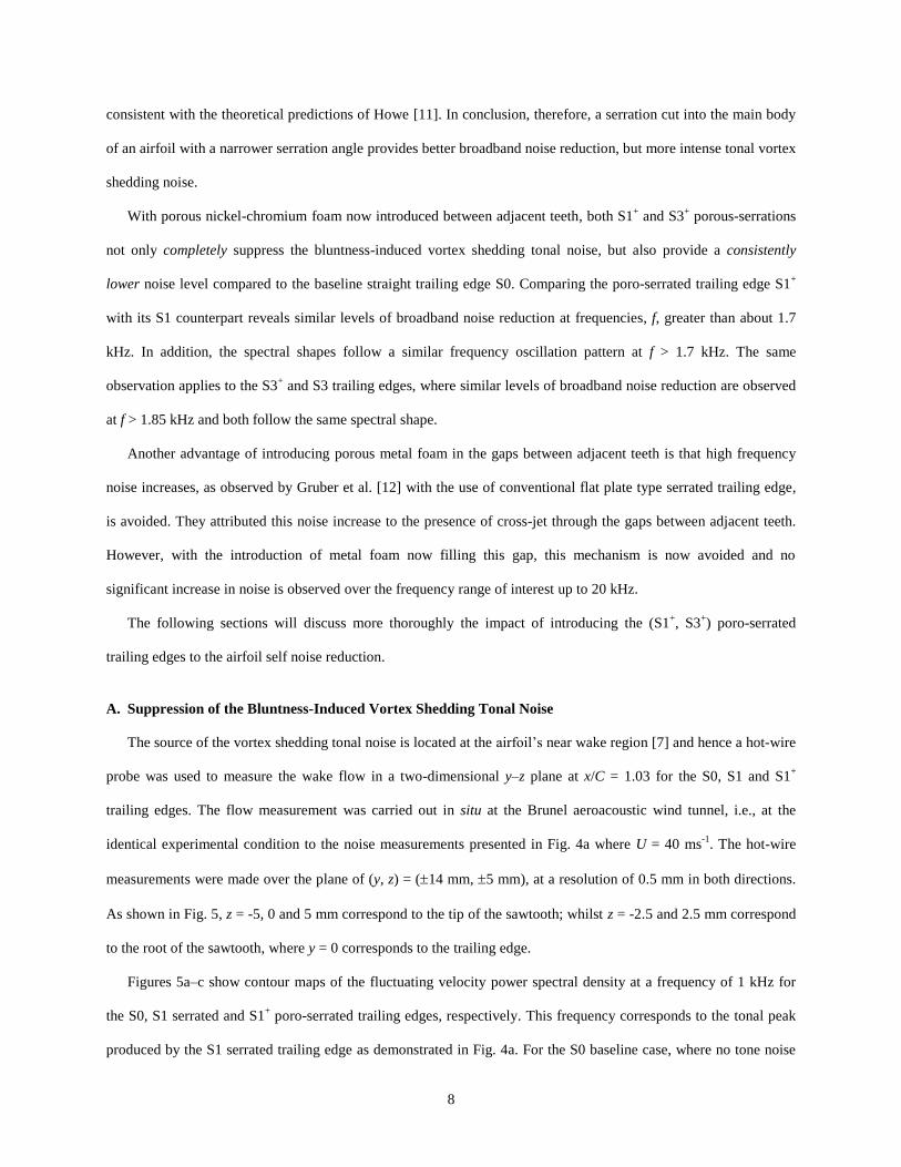
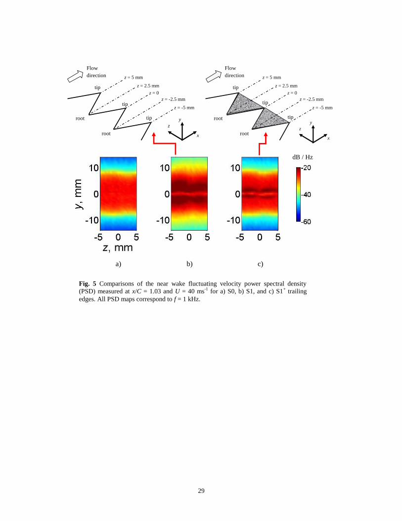
The source of the vortex shedding tonal noise is located at the airfoil’s near wake region [7] and hence a hot-wire
probe was used to measure the wake flow in a two-dimensional y–z plane at x/C = 1.03 for the S0, S1 and S1+
trailing edges. The flow measurement was carried out in situ at the Brunel aeroacoustic wind tunnel, i.e., at the
identical experimental condition to the noise measurements presented in Fig. 4a where U = 40 ms-1
. The hot-wire
measurements were made over the plane of (y, z) = (14 mm, 5 mm), at a resolution of 0.5 mm in both directions.
As shown in Fig. 5, z = -5, 0 and 5 mm correspond to the tip of the sawtooth; whilst z = -2.5 and 2.5 mm correspond
to the root of the sawtooth, where y = 0 corresponds to the trailing edge.
Figures 5a–c show contour maps of the fluctuating velocity power spectral density at a frequency of 1 kHz for
the S0, S1 serrated and S1+ poro-serrated trailing edges, respectively. This frequency corresponds to the tonal peak
produced by the S1 serrated trailing edge as demonstrated in Fig. 4a. For the S0 baseline case, where no tone noise

9
is observed, the fluctuating velocity spectrum is uniform across the spanwise (z) direction. However, for the nonflat
plate S1 serrated trailing edge in Fig. 5b, the level of velocity fluctuation is much higher. Large velocity fluctuation
can also extend to the otherwise freestream region (y > 12 mm y < -12 mm). The large velocity fluctuation is seen
to be fairly uniform across the z direction, thus lending further support to the notion that stronger coherent vortex
shedding can be produced by a narrow angle serrated trailing edge.
As soon as the gaps between adjacent members of the sawtooth are filled with the porous metal foams (S1+), Fig.
5c indicates that the fluctuating velocity PSD contour map becomes almost identical with that produced by the
baseline S0 trailing edge. The only exception is that the S1+ poro-serrated trailing edge produces extra feature
comprising two narrow and wavy lines of turbulent structures mirrored at around the y = 0 line. These are likely to
be caused by the rough surface of the porous metal foams where the turbulence level of the near wall boundary layer
is enhanced. Based on the geometry of the S1+ poro-serrated trailing edge, if the effective length of the porous
material at a specific z location is denoted by lp(z), then lp(z) = (tan)-1
z, where 0 < z < 2.5 mm. The waviness of
the turbulent structures is therefore due to the periodic variation of lp(z), i.e. maximum near the sawtooth roots (z =
2.5 mm) but minimum at the sawtooth tip (z = 0, 5 mm). Note that footprints of these wavy turbulent structures
could persist up to f 10 kHz.
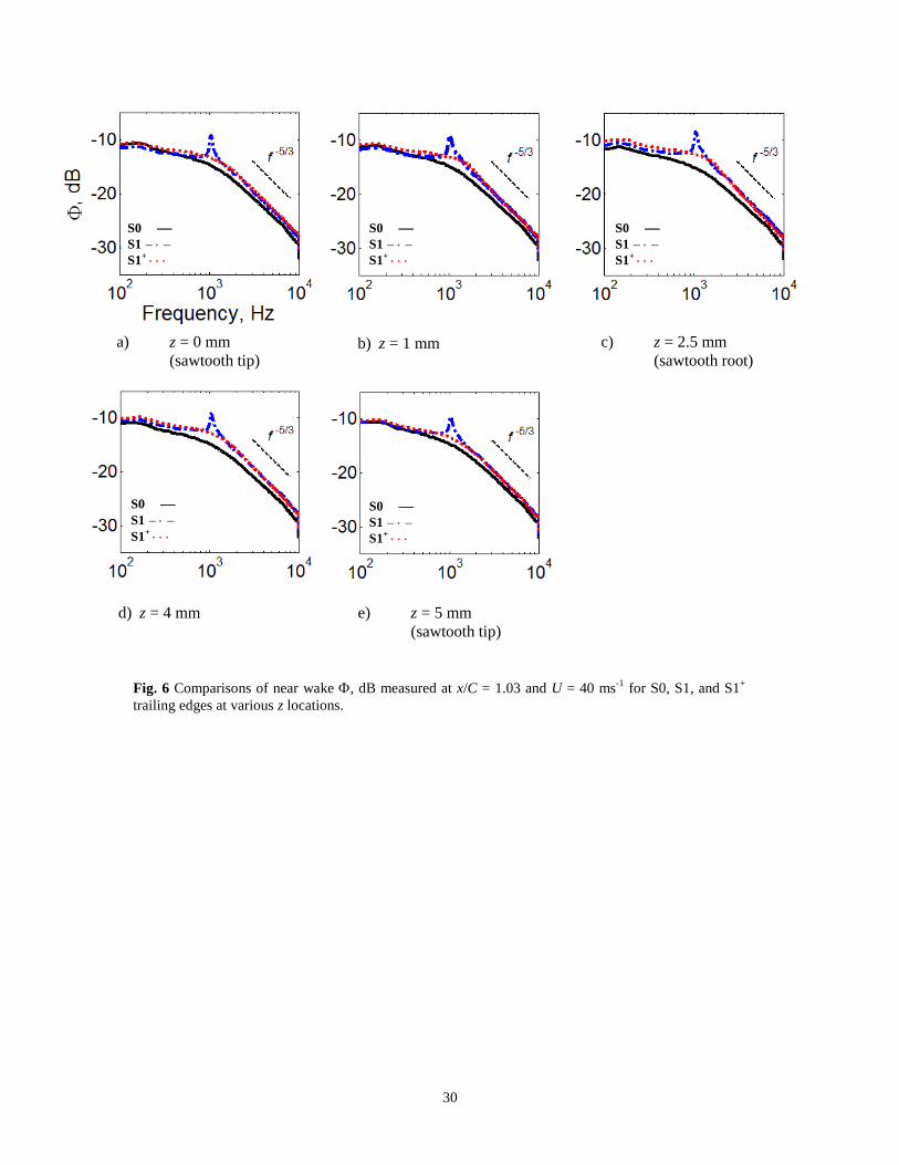
The overall wake power spectral density at a particular z location, (z, f), can be estimated from:
dyf,z,yf,z 10log 10 (1)
where (y, z, f) is the mean square fluctuating velocity in the wake flow. Figures 6a–e compare the (z, f) for the
S0, S1 and S1+ serrations at z = 0 (tip), z = 1 mm, z = 2.5 mm (root), z = 4 mm and z = 5 mm (tip), respectively. All
the S0, S1 and S1+ PSD feature the same high frequency roll-off of f
-5/3, indicating that the wake flow is turbulent.
The dominant narrowband peaks in the wake for the S1 serrated trailing edge, which occur at approximately 1 kHz,
match exactly the acoustic tones measured by the free field microphone in Fig. 4a. When the serrated trailing edge is
replaced by the S1+ poro-serration the narrowband peaks in the wake are completely suppressed across the whole
range of z. The levels produced by the S0 baseline, S1 serrated and S1+ poro-serrated trailing edges are quite
similar beyond the tone frequency (i.e. f > 1 kHz), especially close to the sawtooth tip at z = 0 and 5 mm. However,
near the sawtooth root region of z = 2.5 mm, both the S1 serrated and S1+ poro-serrated trailing edges produce
slightly higher level than the S0 case at f > 1.5 kHz. This is likely to be caused by the largest bluntness at this
10
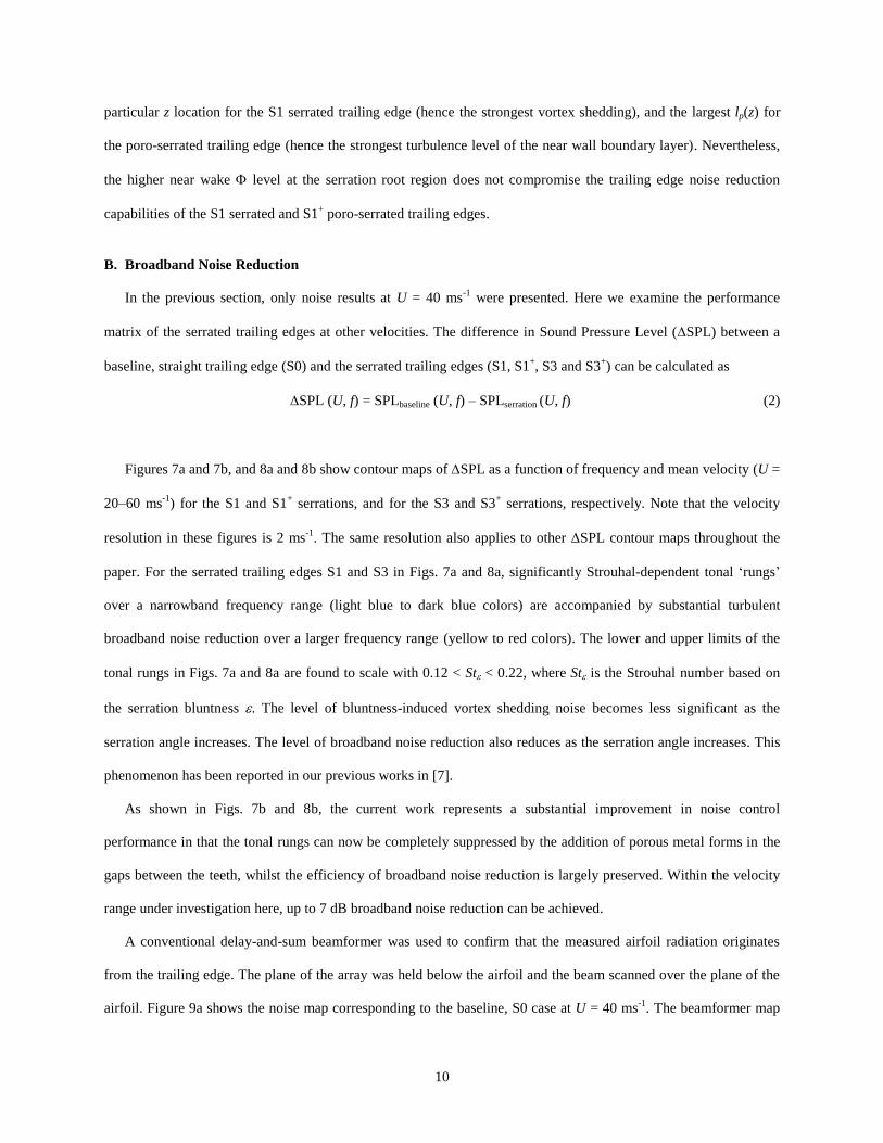
particular z location for the S1 serrated trailing edge (hence the strongest vortex shedding), and the largest lp(z) for
the poro-serrated trailing edge (hence the strongest turbulence level of the near wall boundary layer). Nevertheless,
the higher near wake level at the serration root region does not compromise the trailing edge noise reduction
capabilities of the S1 serrated and S1+ poro-serrated trailing edges.
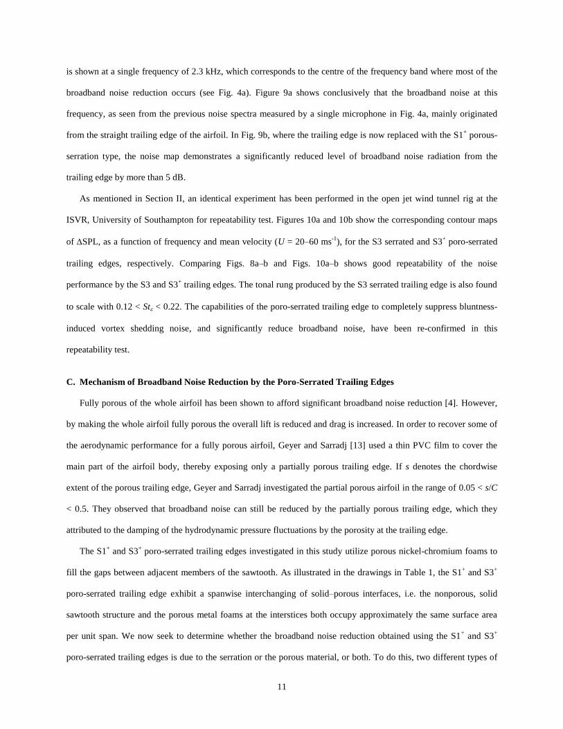
B. Broadband Noise Reduction
In the previous section, only noise results at U = 40 ms-1
were presented. Here we examine the performance
matrix of the serrated trailing edges at other velocities. The difference in Sound Pressure Level (SPL) between a
baseline, straight trailing edge (S0) and the serrated trailing edges (S1, S1+, S3 and S3
+) can be calculated as
SPL (U, f) = SPLbaseline (U, f) – SPLserration (U, f) (2)
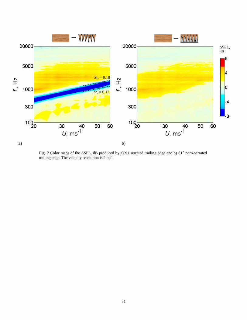
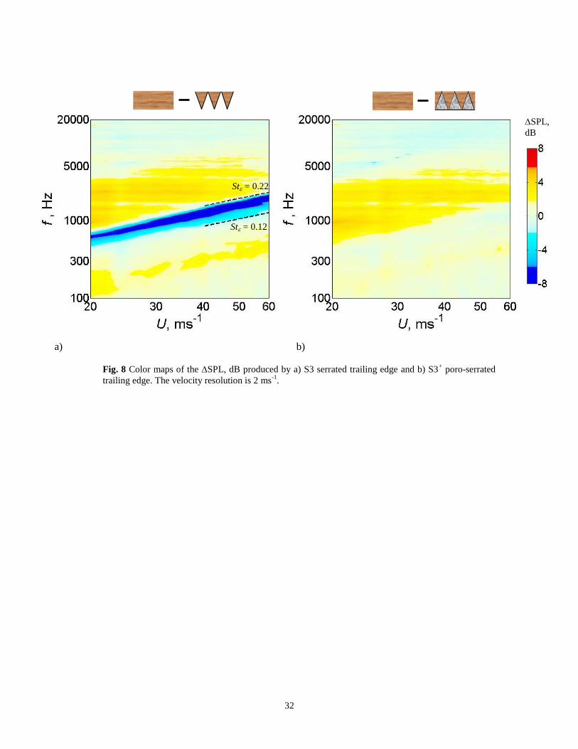
Figures 7a and 7b, and 8a and 8b show contour maps of SPL as a function of frequency and mean velocity (U =
20–60 ms-1
) for the S1 and S1+ serrations, and for the S3 and S3
+ serrations, respectively. Note that the velocity
resolution in these figures is 2 ms-1
. The same resolution also applies to other SPL contour maps throughout the
paper. For the serrated trailing edges S1 and S3 in Figs. 7a and 8a, significantly Strouhal-dependent tonal ‘rungs’
over a narrowband frequency range (light blue to dark blue colors) are accompanied by substantial turbulent
broadband noise reduction over a larger frequency range (yellow to red colors). The lower and upper limits of the
tonal rungs in Figs. 7a and 8a are found to scale with 0.12 < St < 0.22, where St is the Strouhal number based on
the serration bluntness . The level of bluntness-induced vortex shedding noise becomes less significant as the
serration angle increases. The level of broadband noise reduction also reduces as the serration angle increases. This
phenomenon has been reported in our previous works in [7].
As shown in Figs. 7b and 8b, the current work represents a substantial improvement in noise control
performance in that the tonal rungs can now be completely suppressed by the addition of porous metal forms in the
gaps between the teeth, whilst the efficiency of broadband noise reduction is largely preserved. Within the velocity
range under investigation here, up to 7 dB broadband noise reduction can be achieved.
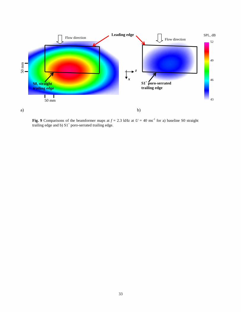
A conventional delay-and-sum beamformer was used to confirm that the measured airfoil radiation originates
from the trailing edge. The plane of the array was held below the airfoil and the beam scanned over the plane of the
airfoil. Figure 9a shows the noise map corresponding to the baseline, S0 case at U = 40 ms-1
. The beamformer map
11
is shown at a single frequency of 2.3 kHz, which corresponds to the centre of the frequency band where most of the
broadband noise reduction occurs (see Fig. 4a). Figure 9a shows conclusively that the broadband noise at this
frequency, as seen from the previous noise spectra measured by a single microphone in Fig. 4a, mainly originated
from the straight trailing edge of the airfoil. In Fig. 9b, where the trailing edge is now replaced with the S1+ porous-
serration type, the noise map demonstrates a significantly reduced level of broadband noise radiation from the
trailing edge by more than 5 dB.
As mentioned in Section II, an identical experiment has been performed in the open jet wind tunnel rig at the
ISVR, University of Southampton for repeatability test. Figures 10a and 10b show the corresponding contour maps
of SPL, as a function of frequency and mean velocity (U = 20–60 ms-1
), for the S3 serrated and S3+ poro-serrated
trailing edges, respectively. Comparing Figs. 8a–b and Figs. 10a–b shows good repeatability of the noise
performance by the S3 and S3+ trailing edges. The tonal rung produced by the S3 serrated trailing edge is also found
to scale with 0.12 < St < 0.22. The capabilities of the poro-serrated trailing edge to completely suppress bluntness-
induced vortex shedding noise, and significantly reduce broadband noise, have been re-confirmed in this
repeatability test.
C. Mechanism of Broadband Noise Reduction by the Poro-Serrated Trailing Edges
Fully porous of the whole airfoil has been shown to afford significant broadband noise reduction [4]. However,
by making the whole airfoil fully porous the overall lift is reduced and drag is increased. In order to recover some of
the aerodynamic performance for a fully porous airfoil, Geyer and Sarradj [13] used a thin PVC film to cover the
main part of the airfoil body, thereby exposing only a partially porous trailing edge. If s denotes the chordwise
extent of the porous trailing edge, Geyer and Sarradj investigated the partial porous airfoil in the range of 0.05 < s/C
< 0.5. They observed that broadband noise can still be reduced by the partially porous trailing edge, which they
attributed to the damping of the hydrodynamic pressure fluctuations by the porosity at the trailing edge.
The S1+ and S3
+ poro-serrated trailing edges investigated in this study utilize porous nickel-chromium foams to
fill the gaps between adjacent members of the sawtooth. As illustrated in the drawings in Table 1, the S1+ and S3
+
poro-serrated trailing edge exhibit a spanwise interchanging of solid–porous interfaces, i.e. the nonporous, solid
sawtooth structure and the porous metal foams at the interstices both occupy approximately the same surface area
per unit span. We now seek to determine whether the broadband noise reduction obtained using the S1+ and S3
+
poro-serrated trailing edges is due to the serration or the porous material, or both. To do this, two different types of
12
trailing edge devices were manufactured and their noise spectra were measured under the same flow condition as the
S1+ and S3
+ cases.
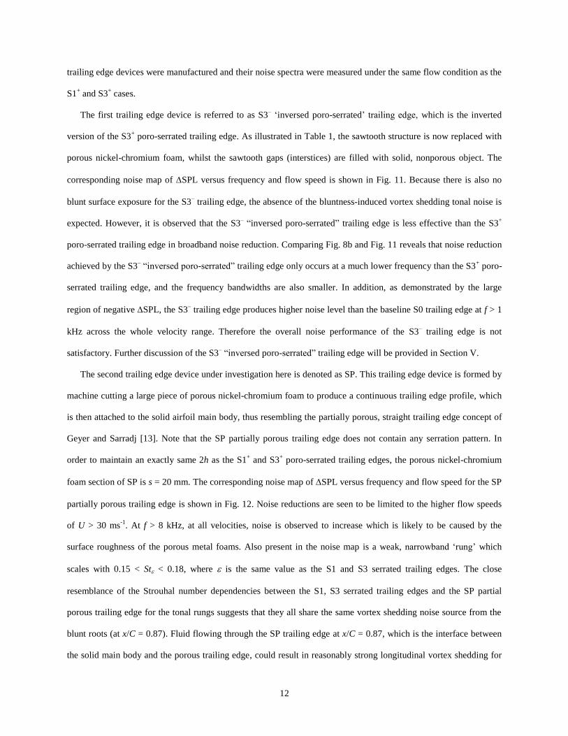
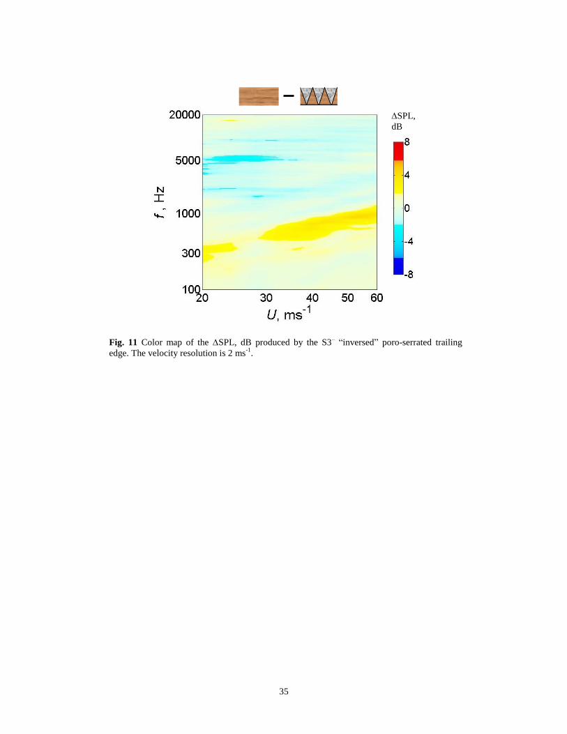
The first trailing edge device is referred to as S3– ‘inversed poro-serrated’ trailing edge, which is the inverted
version of the S3+ poro-serrated trailing edge. As illustrated in Table 1, the sawtooth structure is now replaced with
porous nickel-chromium foam, whilst the sawtooth gaps (interstices) are filled with solid, nonporous object. The
corresponding noise map of SPL versus frequency and flow speed is shown in Fig. 11. Because there is also no
blunt surface exposure for the S3– trailing edge, the absence of the bluntness-induced vortex shedding tonal noise is
expected. However, it is observed that the S3– “inversed poro-serrated” trailing edge is less effective than the S3
+
poro-serrated trailing edge in broadband noise reduction. Comparing Fig. 8b and Fig. 11 reveals that noise reduction
achieved by the S3– “inversed poro-serrated” trailing edge only occurs at a much lower frequency than the S3
+ poro-
serrated trailing edge, and the frequency bandwidths are also smaller. In addition, as demonstrated by the large
region of negative SPL, the S3– trailing edge produces higher noise level than the baseline S0 trailing edge at f > 1
kHz across the whole velocity range. Therefore the overall noise performance of the S3– trailing edge is not
satisfactory. Further discussion of the S3– “inversed poro-serrated” trailing edge will be provided in Section V.
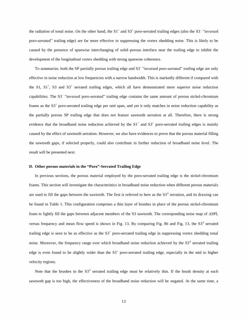
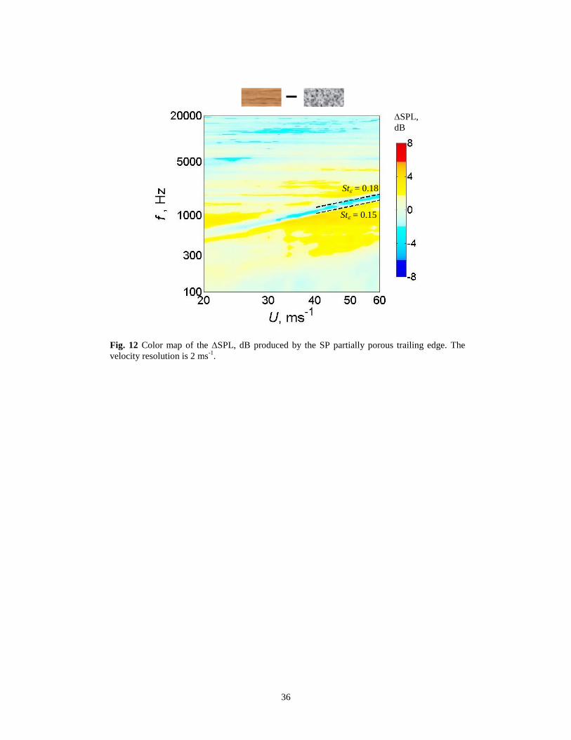
The second trailing edge device under investigation here is denoted as SP. This trailing edge device is formed by
machine cutting a large piece of porous nickel-chromium foam to produce a continuous trailing edge profile, which
is then attached to the solid airfoil main body, thus resembling the partially porous, straight trailing edge concept of
Geyer and Sarradj [13]. Note that the SP partially porous trailing edge does not contain any serration pattern. In
order to maintain an exactly same 2h as the S1+ and S3
+ poro-serrated trailing edges, the porous nickel-chromium
foam section of SP is s = 20 mm. The corresponding noise map of SPL versus frequency and flow speed for the SP
partially porous trailing edge is shown in Fig. 12. Noise reductions are seen to be limited to the higher flow speeds
of U > 30 ms-1
. At f > 8 kHz, at all velocities, noise is observed to increase which is likely to be caused by the
surface roughness of the porous metal foams. Also present in the noise map is a weak, narrowband ‘rung’ which
scales with 0.15 < St < 0.18, where is the same value as the S1 and S3 serrated trailing edges. The close
resemblance of the Strouhal number dependencies between the S1, S3 serrated trailing edges and the SP partial
porous trailing edge for the tonal rungs suggests that they all share the same vortex shedding noise source from the
blunt roots (at x/C = 0.87). Fluid flowing through the SP trailing edge at x/C = 0.87, which is the interface between
the solid main body and the porous trailing edge, could result in reasonably strong longitudinal vortex shedding for
13
the radiation of tonal noise. On the other hand, the S1+ and S3
+ poro-serrated trailing edges (also the S3
– “inversed
poro-serrated” trailing edge) are far more effective in suppressing the vortex shedding noise. This is likely to be
caused by the presence of spanwise interchanging of solid–porous interface near the trailing edge to inhibit the
development of the longitudinal vortex shedding with strong spanwise coherence.
To summarize, both the SP partially porous trailing edge and S3– “inversed poro-serrated” trailing edge are only
effective in noise reduction at low frequencies with a narrow bandwidth. This is markedly different if compared with
the S1, S1+, S3 and S3
+ serrated trailing edges, which all have demonstrated more superior noise reduction
capabilities. The S3– “inversed poro-serrated” trailing edge contains the same amount of porous nickel-chromium
foams as the S3+ poro-serrated trailing edge per unit span, and yet it only matches in noise reduction capability as
the partially porous SP trailing edge that does not feature sawtooth serration at all. Therefore, there is strong
evidence that the broadband noise reduction achieved by the S1+ and S3
+ poro-serrated trailing edges is mainly
caused by the effect of sawtooth serration. However, we also have evidences to prove that the porous material filling
the sawtooth gaps, if selected properly, could also contribute in further reduction of broadband noise level. The
result will be presented next.
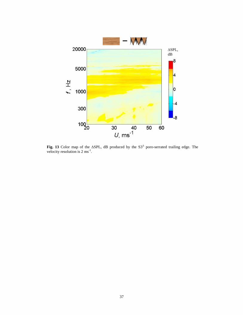
D. Other porous materials in the “Poro”-Serrated Trailing Edge
In previous sections, the porous material employed by the poro-serrated trailing edge is the nickel-chromium
foams. This section will investigate the characteristics in broadband noise reduction when different porous materials
are used to fill the gaps between the sawtooth. The first is referred to here as the S3 serration, and its drawing can
be found in Table 1. This configuration comprises a thin layer of brushes in place of the porous nickel-chromium
foam to lightly fill the gaps between adjacent members of the S3 sawtooth. The corresponding noise map of SPL
versus frequency and mean flow speed is shown in Fig. 13. By comparing Fig. 8b and Fig. 13, the S3 serrated
trailing edge is seen to be as effective as the S3+ poro-serrated trailing edge in suppressing vortex shedding tonal
noise. Moreover, the frequency range over which broadband noise reduction achieved by the S3 serrated trailing
edge is even found to be slightly wider than the S3+ poro-serrated trailing edge, especially in the mid to higher
velocity regions.
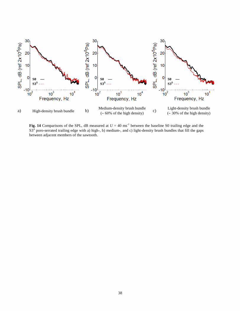
Note that the brushes in the S3 serrated trailing edge must be relatively thin. If the brush density at each
sawtooth gap is too high, the effectiveness of the broadband noise reduction will be negated. At the same time, a
14
noticeable level of noise increase at high frequency is also observed. This behavior is reflected in Figs. 14a–c for the
noise spectra measured at U = 40 ms-1
by the S3 serrated trailing edge with “high-density”, “medium-density” and
“light-density” brushes at the sawtooth gaps. Note that the “medium-density” and “light-density” brushes are
approximately 60% and 30%, respectively, of the “high-density” brush. The results demonstrate that the overall
noise performance improves as the brush density reduces.
The above observations of wider frequency range of +SPL (broadband noise reduction) achieved by S3, and
the dependence of brush density in the overall noise performance strongly suggest that the porous material on the
sawtooth gaps could also play a positive role in the turbulent broadband noise reduction.
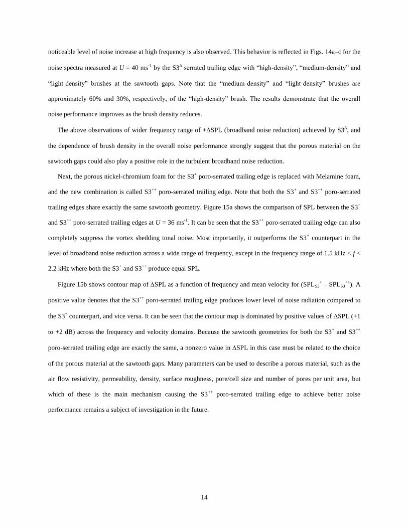
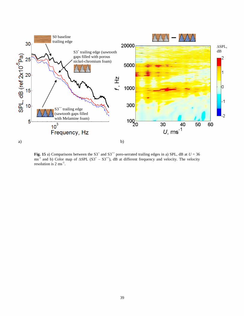
Next, the porous nickel-chromium foam for the S3+ poro-serrated trailing edge is replaced with Melamine foam,
and the new combination is called S3++
poro-serrated trailing edge. Note that both the S3+ and S3
++ poro-serrated
trailing edges share exactly the same sawtooth geometry. Figure 15a shows the comparison of SPL between the S3+
and S3++
poro-serrated trailing edges at U = 36 ms-1
. It can be seen that the S3++
poro-serrated trailing edge can also
completely suppress the vortex shedding tonal noise. Most importantly, it outperforms the S3+ counterpart in the
level of broadband noise reduction across a wide range of frequency, except in the frequency range of 1.5 kHz < f <
2.2 kHz where both the S3+ and S3
++ produce equal SPL.
Figure 15b shows contour map of SPL as a function of frequency and mean velocity for (SPLS3+ – SPLS3
++). A
positive value denotes that the S3++
poro-serrated trailing edge produces lower level of noise radiation compared to
the S3+ counterpart, and vice versa. It can be seen that the contour map is dominated by positive values of SPL (+1
to +2 dB) across the frequency and velocity domains. Because the sawtooth geometries for both the S3+ and S3
++
poro-serrated trailing edge are exactly the same, a nonzero value in SPL in this case must be related to the choice
of the porous material at the sawtooth gaps. Many parameters can be used to describe a porous material, such as the
air flow resistivity, permeability, density, surface roughness, pore/cell size and number of pores per unit area, but
which of these is the main mechanism causing the S3++
poro-serrated trailing edge to achieve better noise
performance remains a subject of investigation in the future.
15
IV. Aerodynamic Performance
As discussed in Section I most of the early serrated trailing edges have been in the form of flat plate inserts.
However, the artificial lengthening of the airfoil geometry could affect the global flow circulation around it, thus
possibly leading to modification in the aerodynamic performance.
The proposed nonflat plate type serrated trailing edge preserves the original airfoil shape with the advantage that
aerodynamic performance is not compromised significantly. This section will investigate the effect of these various
serrations on the lift coefficient (CL) and drag coefficient (CD) of the NACA0012 airfoil with the S1+ and S3
+ poro-
serrated trailing edges from 0o to 20
o angle of attack (). As mentioned in Section II force measurements were
carried out in a wind tunnel with a closed-test section. Flow conditions are therefore different from the open jet wind
tunnel used for the noise test but are still useful for assessing changes in the aerodynamic performance. The velocity
of the wind tunnel was set at 30 ms-1
during the force measurement. For consistency the tripping elements near the
airfoil’s leading edge on both sides were retained.
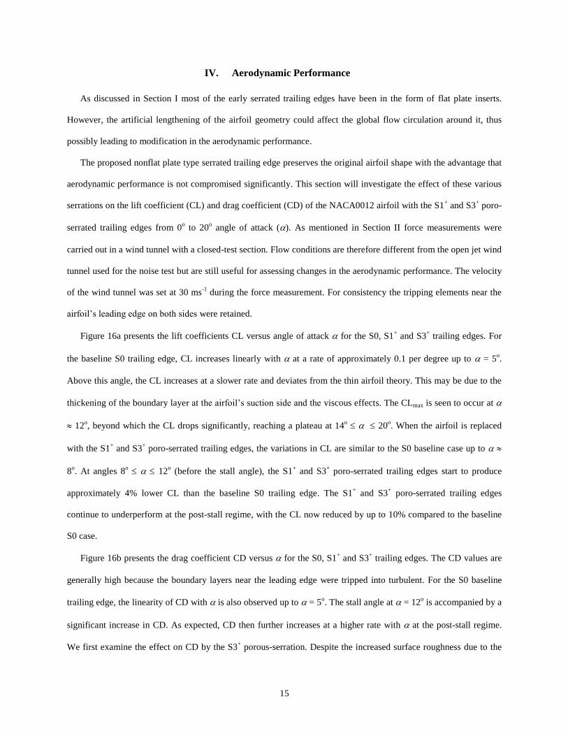
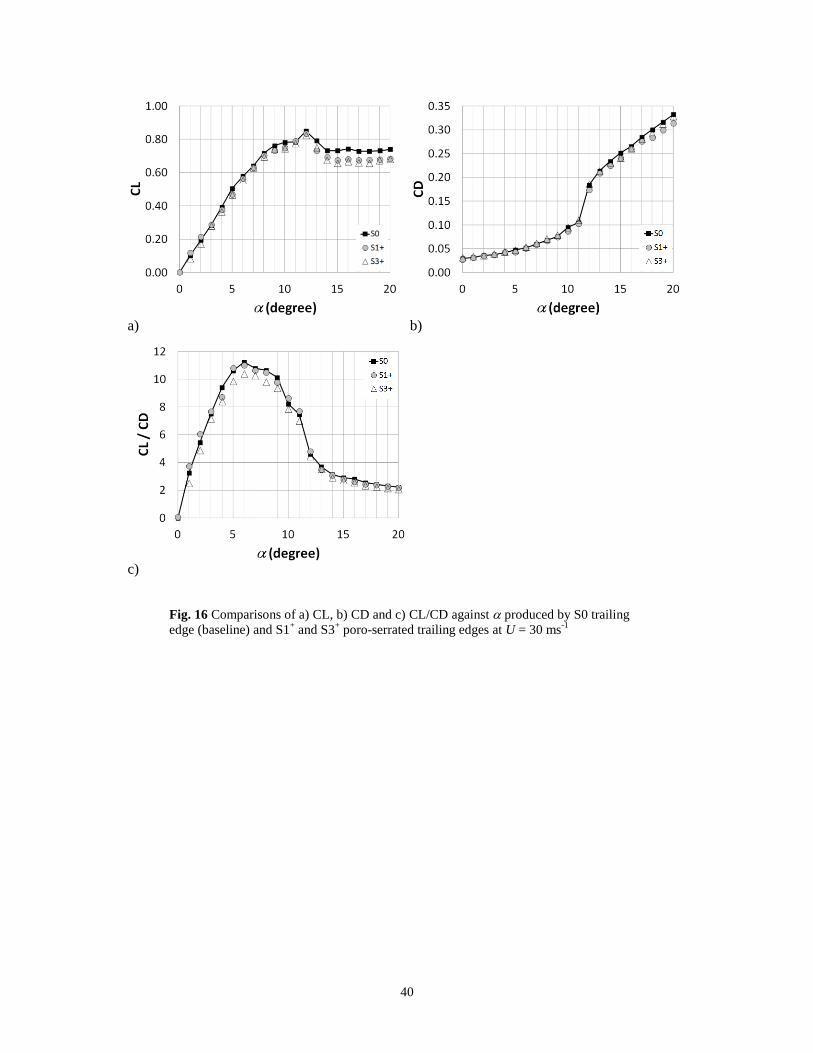
Figure 16a presents the lift coefficients CL versus angle of attack for the S0, S1+ and S3
+ trailing edges. For
the baseline S0 trailing edge, CL increases linearly with at a rate of approximately 0.1 per degree up to = 5o.
Above this angle, the CL increases at a slower rate and deviates from the thin airfoil theory. This may be due to the
thickening of the boundary layer at the airfoil’s suction side and the viscous effects. The CLmax is seen to occur at
12o, beyond which the CL drops significantly, reaching a plateau at 14
o 20
o. When the airfoil is replaced
with the S1+ and S3
+ poro-serrated trailing edges, the variations in CL are similar to the S0 baseline case up to
8o. At angles 8
o 12
o (before the stall angle), the S1
+ and S3
+ poro-serrated trailing edges start to produce
approximately 4% lower CL than the baseline S0 trailing edge. The S1+ and S3
+ poro-serrated trailing edges
continue to underperform at the post-stall regime, with the CL now reduced by up to 10% compared to the baseline
S0 case.
Figure 16b presents the drag coefficient CD versus for the S0, S1+ and S3
+ trailing edges. The CD values are
generally high because the boundary layers near the leading edge were tripped into turbulent. For the S0 baseline
trailing edge, the linearity of CD with is also observed up to = 5o. The stall angle at = 12
o is accompanied by a
significant increase in CD. As expected, CD then further increases at a higher rate with at the post-stall regime.
We first examine the effect on CD by the S3+ porous-serration. Despite the increased surface roughness due to the
16
porous metal foams, CD associated with the S3+ poro-serrated trailing edge follows almost exactly the same trend as
the baseline S0 trailing edge throughout the pre-stall, and post-stall regimes up to = 14o. At > 14
o, the S3
+ poro-
serrated trailing edge even produces lower CD than the baseline S0 case. This phenomenon is further replicated by
the S1+ poro-serrated trailing edge. Notwithstanding the same CD values produced at 0
0 14
o, the S1
+ poro-
serrated trailing edge performs better than the S0 trailing edge at > 14o, affording a maximum of 6% lower drag.
What causes the poro-serrated trailing edge to produce lower lift and lower drag than the straight trailing edge at
the post-stall regime remains unclear. One possible explanation is that the porous material near the trailing edge
allows “communication” of boundary layers between the suction side and pressure side. Such a communication will
cause an overall reduction in thickness of the shear layer leaving the trailing edge, hence the drag, as a result of flow
dissipations through the porous metal foams. Similarly, the communication of boundary layers between the suction
side and pressure side might displace the aft stagnation point, which could lead to a change of flow circulation
around the airfoil, hence the lift. Note that these conjectures only apply to very large angle of attack cases when the
pressure difference across the porous metal foams near the trailing edge is also large.
Another useful parameter used to examine the aerodynamic performance of the serrated airfoil is the lift-to-drag
ratio (CL/CD). A large value of CL/CD is desired as it entails the maximum lift force generation with minimal drag
penalty. Figure 16c shows the CL/CD versus for the S0, S1+ and S3
+ trailing edges. For the baseline S0 trailing
edge, the ratio CL/CD increases steadily with , reaching a maximum value at = 6o. Between 6
o 9
o, CL/CD
falls steadily. After that the CL/CD undergoes a significant drop at = 10o. A second significant drop happens again
at = 12o, corresponding to the stall angle. At > 12
o, at the post-stall regime, the CL/CD steadily declines with .
Examination of the S3+ poro-serrated trailing edge reveals that its CL/CD is consistently lower than the baseline S0
case. The largest discrepancy occurs at 4o 9
o, where up to a 17% difference is obtained. However, the S1
+
poro-serrated trailing edge, which has a narrower serration angle, recovers its CL/CD to almost the same level as the
baseline S0 trailing edge throughout the range of in both the pre-stall and post-stall regimes. The remarkable
recovery of CL/CD by the S1+ poro-serrated trailing edge is thus very encouraging.
Although the aerodynamic results provided in this section are far from exhaustive, they suggest that the best
recovery of the aerodynamic performances for a poro-serrated trailing edge is related to the one with the smallest
serration angle . This finding could have anticipated because the smallest serration angle entails a more significant
discontinuity of the porous metal foams in the spanwise direction, and that a constant porous medium as part of an
17
airfoil is likely to be more detrimental for its aerodynamic forces. Remarkably, the criterion of low serration angle
for maintaining the aerodynamic performances is the same for achieving the optimal broadband noise reduction.
V. Discussions
Sections III.A and III.B of this paper have demonstrated the capability of the S1+ and S3
+ poro-serrated trailing
edges to completely suppress vortex shedding tonal noise that would otherwise be produced by the S1 and S3
serrated trailing edges, whilst at the same time maintaining the same level of broadband noise reduction. We have
confirmed that broadband noise reductions by the S1+ and S3
+ poro-serrated trailing edges are mainly caused by the
serration effect (in Section III.C), even though by filling the gaps between adjacent members of the sawtooth in S1+
and S3+ a seemingly “straight” trailing edge is formed (see Figs. 17a–b). However, further question remains for the
increased surface roughness introduced by the porous nickel-chromium foams and its implication to the noise
radiation.
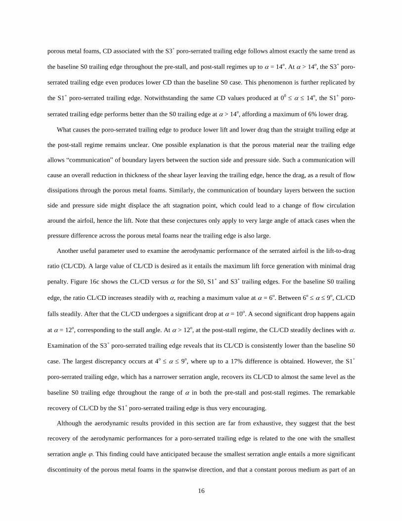
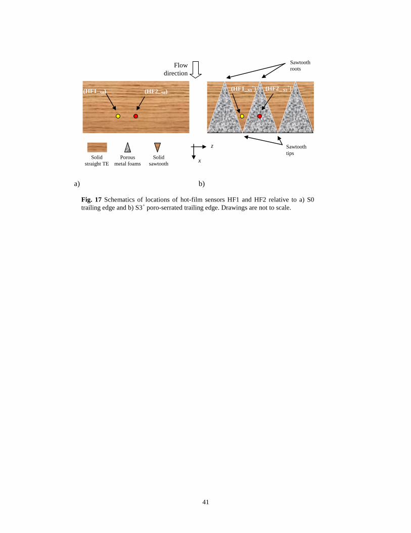
To address these issues two surface-mounted hot-film sensors (HF1 and HF2) were located onto the baseline S0,
and the S3+ poro-serrated trailing edges at x/C 0.95 but spaced 6 mm apart (z) in the spanwise direction. This
spanwise spacing for the S3+ poro-serrated trailing edge is designed such that one hot-film sensor (HF1) is situated
within the solid, nonporous sawtooth surface, while another hot-film sensor (HF2) is situated within the porous
metal foam, as illustrated in Fig. 17b. The exact locations of HF1 and HF2 in the S3+ poro-serrated trailing edge are
replicated in the S0 straight trailing edge (Fig. 17a), though both hot-film sensors are now situated on the solid
surface.
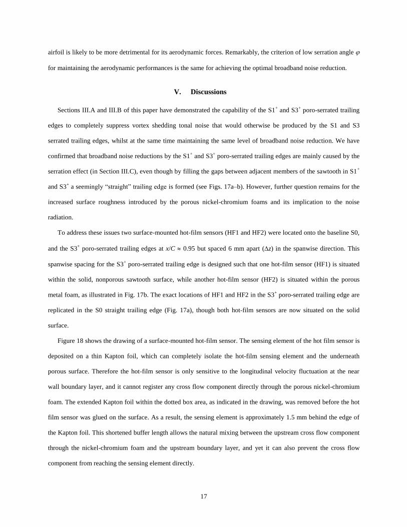
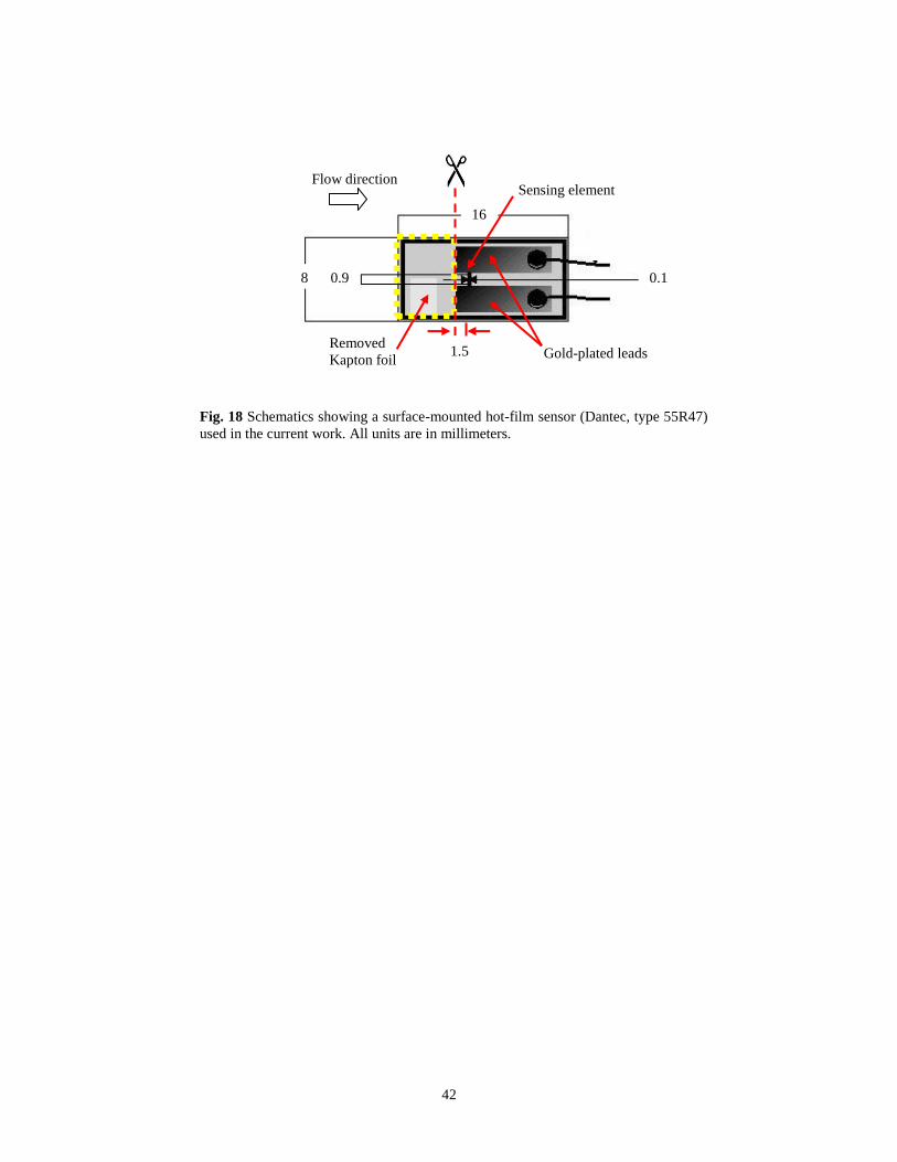
Figure 18 shows the drawing of a surface-mounted hot-film sensor. The sensing element of the hot film sensor is
deposited on a thin Kapton foil, which can completely isolate the hot-film sensing element and the underneath
porous surface. Therefore the hot-film sensor is only sensitive to the longitudinal velocity fluctuation at the near
wall boundary layer, and it cannot register any cross flow component directly through the porous nickel-chromium
foam. The extended Kapton foil within the dotted box area, as indicated in the drawing, was removed before the hot
film sensor was glued on the surface. As a result, the sensing element is approximately 1.5 mm behind the edge of
the Kapton foil. This shortened buffer length allows the natural mixing between the upstream cross flow component
through the nickel-chromium foam and the upstream boundary layer, and yet it can also prevent the cross flow
component from reaching the sensing element directly.
18
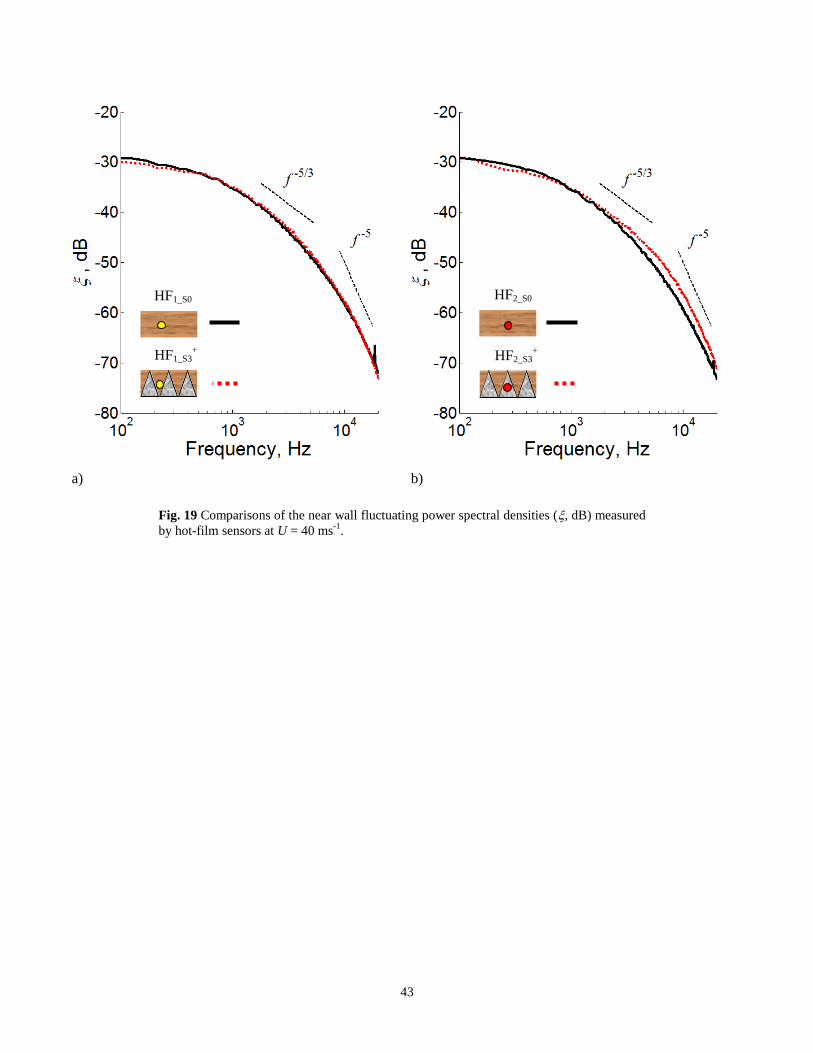
The fluctuating signals measured by the hot-film sensor are non-dimensionalized by their standard deviation
values, respectively. Figure 19a shows the corresponding power spectral densities measured by the HF1_S0 and
HF1_S3+ sensors at U = 40 ms
-1. Note that the subscript denotes a particular type of trailing edge used. The mid-
frequency and high-frequency roll-off of approximately f -5/3
and f -5
, respectively, for both HF1_S0 and HF1_S3+
suggest that the turbulent boundary layer is fully developed (this might only be true at x/C = 0.95. As shown in [14],
the existence of some oblique vortical structures along the side edges of the solid-surfaced sawtooth is likely to yield
a different PSD characteristic if x/C is closer to unity, i.e. towards the sawtooth tip). On the other hand, as shown in
Fig. 19b, HF2_S3+ (situated on the porous surface) produces slightly lower spectral level at low frequency, but
considerably higher level at f > 2.2 kHz, than the HF2_S0 counterpart.
Measurements of the surface-mounted hot-film signals were also performed at 20 U 60 ms-1
. The following
parameter is introduced:
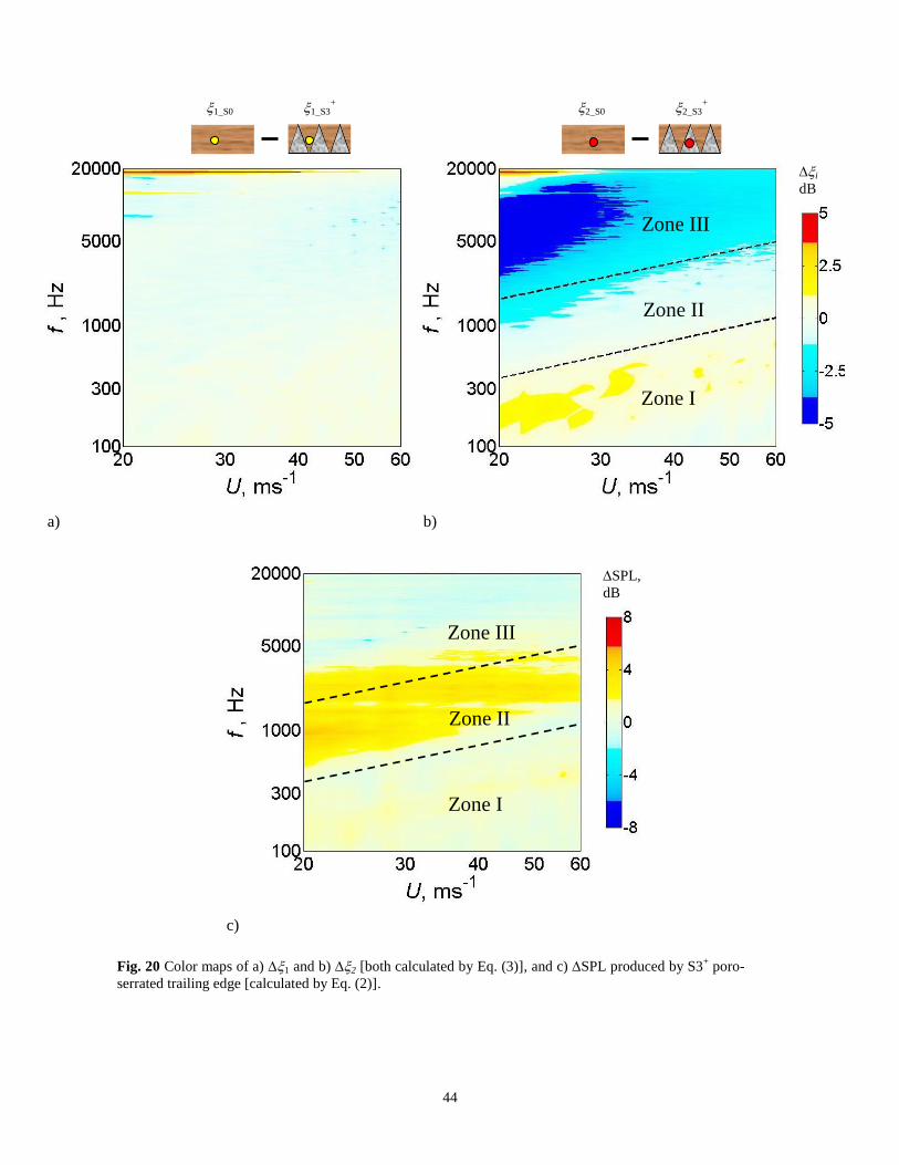
i (U, f) = i_S0 (U, f) – i_S3+ (U, f), (3)
where is the power spectral density level measured by a particular type of hot-film sensor, i = 1 or 2, for either the
S0 and S3+ trailing edges. 1 is designed to show the difference in power spectral density levels between HF1_S0
and HF1_S3+, where both hot-film sensors are situated on solid surfaces. Likewise, 2 will show the difference in
power spectral density levels between HF2_S0 and HF2_S3+, but the HF2_S0 is situated on a solid surface and the
HF2_S3+ is on a porous surface. The largely zero value of 1 in Fig. 20a confirms that both the power spectral
densities at locations HF1_S0 and HF1_S3+ are similar throughout the frequency–velocity domain. However, the 2
contour in Fig. 20b is noticeable different. Three distinct zones can be identified from Fig. 20b:
1. Zone I (low frequency range) has a slight positive level of 2 up to 2 dB.
2. Zone II (mid frequency range) contains the 2 which is largely close to zero value.
3. Zone III (high frequency range) is characterized by a considerable negative level of 2 up to –6 dB.
A predominantly negative level of 2 in Zone III implies that the porous surface produces higher power spectral
density level than the solid, nonporous surface. We now assume that the power spectral density measured by the hot-
film sensors near the trailing edge shares a close causality with the radiated noise spectrum. The negative level of
2 in Zone III could translate to a noise increase by the S3+ poro-trailing edge at high frequency. A positive level of

19
2 in Zone I (low frequency range) would suggest that noise reduction is possible. Likewise, a zero level of 2 in
Zone II (mid frequency range) could stipulate an unchanged noise level. To verify the above conjectures, Zones I, II
and III identified from Fig. 20b are now embedded into the SPL contour map in Fig. 20c for the S3+ poro-serrated
trailing edge. The following summarizes the outcomes of the comparison:
1. The negative level of 2 in Zone III does not result in significant noise increase at the same zone.
2. Noise reduction at Zone I is not realized despite the slight positive level of 2 at the same zone.
3. Most crucially, most of the broadband noise reduction observed in the SPL actually occurs at Zone II,
where the level of 2 at the same zone is largely zero.
In summary, none of the initial conjectures are true regarding the effect of porous metal foams to the radiated
noise. Despite that the porous metal foam will increase the overall ‘roughness’ of the trailing edge surface, it does
not seem to cause noise increase at high frequency, nor to achieve significant noise reduction at low frequency. The
primary effect of the porous metal foams exerting on the overall noise radiation for the S3+ poro-serrated trailing
edge is to undermine the bluntness exposed by the serration roots, thus avoiding the vortex shedding tonal noise.
Despite that the addition of the porous metal foam will cause the trailing edge appearing ‘straight’, it does not
enhance the scattering efficiency that one would expect from a straight, unserrated trailing edge. Therefore the
broadband noise reduction observed in the SPL contours for the S1+ and S3
+ poro-serrated trailing edges is
primarily caused by the serration effect. Although the hot-film test was not carried out for the S3++
poro-serrated
trailing edge, the mechanism is expected to be the same.
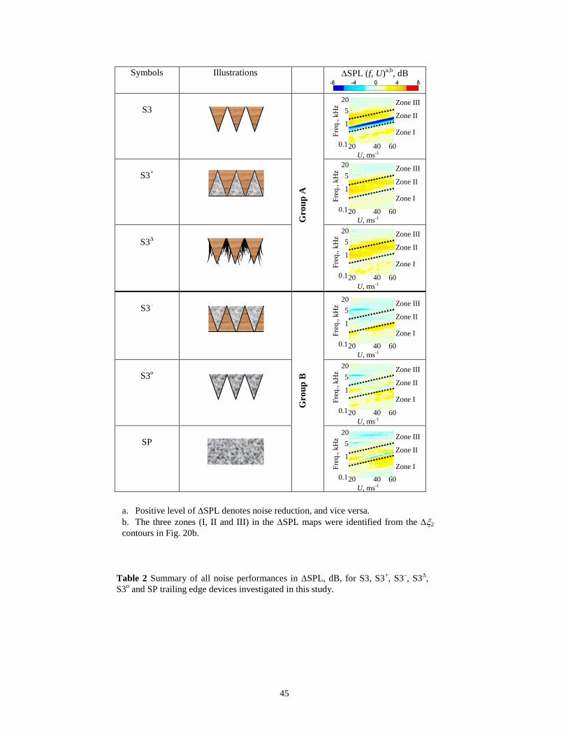
Finally, the results presented thus far could provide a hint about the mechanism underpinning the broadband
noise reduction by the S1+ and S3
+ poro-serrated trailing edges. Table 2 summarizes the SPL(f, U) for the S3-type
trailing edges (S3, S3+, S3
–, S3
and S3
o), as well as the SP. In the table, Zones I, II and III identified from the 2(f,
U) contour in Fig. 20b are also superimposed in each of the SPL(f, U) contour maps. It is clear that the SPL(f, U)
associated with the above trailing edge devices could be categorized into two distinct groups (Group A and Group
B). The S3, S3+ and S3
trailing edges belong to Group A, from which significant broadband noise reduction is
achieved at Zone II. On the other hand, the Group B trailing edges (S3–, S3
o and SP) could only produce noise
reductions in the lower frequency region of Zone I. The frequency bandwidth is also narrower, and these trailing
20
edges seem to be only effective at U > 30 ms-1
. In addition, noticeable level of noise increase actually occurs in most
of Zone III, and in one case occurs in Zone II by the SP trailing edge. Therefore, the fluctuating velocity power
spectral density in the 2 contour (Fig. 20b) share a better correlation with the SPL noise performance produced
by the Group B trailing edges, but not with the poro-serrated trailing edge which belongs to Group A. This suggests
that any property changes in the trailing edge by the porous material (e.g. air flow resistivity, permeability and
surface roughness) is not the primary reason for the broadband noise reduction in Zone II.
A common feature of the Group A trailing edges (S3, S3+ and S3
) is that their sawtooth serrations are made
from nonporous, solid surfaces. Likewise, the sawtooth serrations in Group B (S3– and S3
o), including a partially
porous, unserrated trailing edge in the SP case, are made from porous metal foam. Such distinction stipulates that an
effective broadband noise reduction would require the sawtooth serrations to be made from solid surface. It remains
an interesting question that a sawtooth serration made from porous metal foams, even if it shares the same
geometrical parameters as the sawtooth surface made from solid surface, could not demonstrate a similar capability
in broadband noise reduction. The answer may be related to the acoustical scattering efficiency of the turbulent
wavenumber components on a porous sawtooth serration. This conjecture provides an avenue for further research to
understand the trailing edge noise reduction mechanism by the serration technique.
VI. Conclusions
This paper reports an experimental study on the aeroacoustic properties of a NACA0012 airfoil with a number of
trailing edge devices (S1, S1+, S3, S3
+, S3
++, S3
–, S3
, S3
o and SP). In particular, the poro-serrated trailing edges
S1+, S3
+, S3
++ and S3
represent the core of investigation. All these trailing edge devices, when integrated to an
airfoil body, will retain the original airfoil shape and offer better structural stability than the conventional, flat plate
type serrated trailing edge. The main objective of this work is to investigate whether it is feasible to employ these
new trailing edge devices to reduce the turbulent broadband noise produced by the trailing edge of an airfoil. The
free field noise measurements, as well as the wake flow measurement, were carried out inside an aeroacoustic wind
tunnel facility at Brunel University London. The range of jet speeds under investigation was between 20 ms-1
and 60
ms-1
, corresponding to Reynolds numbers based on airfoil chord of 2 x 10⁵ and 6 x 10
5 respectively. The lift and
drag forces produced by the airfoil when fitted with the poro-serrated trailing edges were measured in a separate
aerodynamic wind tunnel.
21
The use of S1 and S3 serrated trailing edges will result in sound pressure level reduction of the broadband noise
up to 7 dB. However, noise increase caused by the vortex shedding from the exposed blunt roots is also very
significant, especially for the S1 case. The use of porous nickel-chromium foams to fill the gaps between adjacent
members of the sawtooth, as demonstrated by the S1+ and S3
+ poro-serrated trailing edges, can completely suppress
the vortex shedding tonal noise, whilst the level of broadband noise reduction remains the same. These poro-serrated
trailing edges also demonstrated an excellent repeatability in noise performance when they were tested in another
aeroacoustic facility. There is little aerodynamic penalty if these poro-serrated trailing edges are integrated to the
airfoil body. Another benefit these poro-serrated trailing edges exhibits over the flat plate type serrated trailing edge
is the minimal noise increase at high frequency. A trend discernible from the current results is that the S1+ poro-
serrated trailing edge (with a narrower serration angle) performs better acoustically and aerodynamically than the
S3+ counterpart. Both have the same root-to-tip distance (2h).
Although not shown in this paper for clarity, an exactly similar outcome of the broadband noise reduction can be
achieved by these poro-serrated trailing edges when the airfoil is adjusted to non-zero angles of attack, i.e. 0.8o and
2.8o effective angles of attack after applying the corrections of the jet nozzle height.
Another promising concept developed in this study is the S3 poro-serrated trailing edge where the gaps between
adjacent members of sawtooth were partially filled with thin brushes instead of the porous nickel-chromium foams.
The levels of noise reduction for both the vortex shedding tonal noise and the turbulent broadband noise are similar
compared to the S3+ poro-serrated trailing edge. More interestingly, the S3
poro-serrated trailing edge achieves
broadband noise reduction over a wider bandwidth in frequency than the S3+ counterpart, especially at higher
velocity.
Two possible broadband noise reduction mechanisms could be associated with the poro-serrated trailing edges.
One associated with the oblique edges due to the serrations, and the other arising from porosity which allows the
pressure side and suctions side to ‘communicate’ therefore reducing the acoustic dipole strength at the trailing edge.
As discussed in Section III.C, whilst the SP, S1+ and S3
+ trailing edges all used the porous nickel-chromium foams
with the same porous length s, or serration root-to-tip distance 2h, the partial porous trailing edge SP produces very
different SPL characteristics when compared to the S1+ and S3
+ poro-serrated trailing edges. Most importantly, the
SP trailing edge could not match the level and bandwidth of broadband noise reduction achieved by the S1+ and S3
+
poro-serrated trailing edges. Therefore there are clear evidences that the main mechanism underpinning the turbulent
22
broadband noise reduction by a poro-serrated trailing edge should come from the sawtooth serration effect. The
porous nickel-chromium foam, on the other hand, is very effective in undermining the bluntness exposed by the
serration roots, thus suppressing the vortex shedding tonal noise. The interesting outcome of the S3 serrated trailing
edge encourages a further study to replace the porous nickel-chromium foam with Melamine foam at the sawtooth
gaps. This new combination of the poro-serrated trailing edge (S3++
) is found to achieve even greater level of
broadband noise reduction than the S3+ counterpart. Based on all the evidences, whilst the main mechanism
underpinning the broadband noise reduction of a poro-serrated trailing edge comes from the sawtooth serration, the
porous material used to fill the sawtooth gaps has a potential to further reduce the turbulent broadband noise level.
For all the trailing edge devices investigated in this study, two main groups can be formed based on the noise
performances. Group A (S3, S3+ and S3
) is characterized by a solid sawtooth serration and every member within
this group consistently demonstrated a significant trailing edge broadband noise reduction. Group B (S3– and S3
o),
where every member within this group utilizes sawtooth made from porous nickel-chromium foams, offers no
advantage on the broadband noise reduction even though it shares the same geometrical parameters of serration as
Group A. This might imply different acoustical scattering efficiency when the turbulent wavenumber components
propagate on a porous sawtooth serration.
In conclusion, the poro-serrated trailing edges investigated in this paper have the potential to improve the
industrial worthiness of the serration technology in achieving low noise radiation in fan and turbine blades. A viable
path for the continuation of the current work is a parametric study when the poro-serrated trailing edge is subjected
to different sawtooth geometries (e.g. 2h and ) and porous materials with different air flow resistivity, density,
permeability and surface roughness, over a wide range of Reynolds numbers and angles of attack.
Acknowledgments
The authors are grateful for the support from the EPSRC Doctoral Training Grants in the United Kingdom, and
would like to thank Elisa Dubois and Chioma Muhammad for their help in acquiring some of the experimental data.
23
References
[1] Gruber, M., Joseph, P. F. and Chong, T. P., “Experimental Investigation of Airfoil Self Noise and Turbulent Wake Reduction
by the use of Trailing Edge Serrations,” 16th AIAA/CEAS Aeroacoustic Conference and Exhibit, AIAA Paper 2010–3803,
2010, Stockholm, Sweden.
[2] Oerlemnans, S., Fisher, M., Maeder, T. and Korler, K., “Reduction of Wind Turbine Noise using Optimized Airfoils and
Trailing Edge Serrations,” AIAA Journal, Vol. 47, 2009, pp. 1470–1481.
[3] Moreau, D. J. and Doolan C. J., “Noise-Reduction Mechanism of a Flat-Plate Serrated Trailing Edge,” AIAA Journal, Vol. 51,
2013, pp. 2513–2522.
[4] Geyer, T., Sarradj, E. and Fritzsche, C., “Measurement on the Noise Generation at the Trailing Edge of Porous Airfoils,”
Experiment in Fluids, Vol. 48, 2010, pp. 291–308.
[5] Herr, M., “Design Criteria for Low-Noise Trailing-Edges,” 13th AIAA/CEAS Aeroacoustic Conference and Exhibit, AIAA
Paper 2007–3470, 2007, Rome, Italy.
[6] Finez, A., Jondeau, E., Roger, M. and Jacob, M. C., “Broadband Noise Reduction with Trailing Edge Brushes,” 16th
AIAA/CEAS Aeroacoustic Conference, AIAA Paper 2010–3980, 2010, Stockholm, Sweden.
[7] Chong, T. P., Vathylakis, A., Joseph, P. F. and Gruber, M., “Self-Noise Produced by an Airfoil with Nonflat plate Trailing-
Edge Serrations,” AIAA Journal, Vol. 51, 2013, pp. 2665–2677.
[8] Chong, T. P., Joseph, P. F. and Gruber, M., “Airfoil Self Noise Reduction by Non-Flat plate type Trailing Edge Serrations,”
Applied Acoustics, Vol. 74, 2013, pp. 607–613.
[9] Vathylakis, A., Chong, T. P. and Kim, J. H., “Design of a Low-Noise Aeroacoustic Wind Tunnel Facility at Brunel
University,” 20th AIAA/CEAS Aeroacoustic Conference and Exhibit, AIAA Paper 2014–3288, 2014, Atlanta, Georgia.
[10] Chong, T. P., Joseph, P. F. and Davies, P. O. A. L., “Design and Performance of an Open Jet Wind Tunnel for Aero-
Acoustic Measurement,” Applied Acoustics, Vol. 70, 2009, pp. 605–614.
[11] Howe, M. S., “Noise produced by a Sawtooth Trailing Edge,” Journal of the Acoustical Society of America, Vol. 90, 1991,
pp. 482–487.
[12] Gruber, M., Joseph, P. F. and Chong, T. P., “On the Mechanism of Serrated Airfoil Trailing Edge Noise Reduction,” 17th
AIAA/CEAS Aeroacoustic Conference and Exhibit, AIAA Paper 2011–2781, 2011, Portland, Oregon.
[13] Geyer, T. and Sarradj, E., “Trailing Edge Noise of Partially Porous Airfoils,” 20th AIAA/CEAS Aeroacoustic Conference and
Exhibit, AIAA Paper 2014–3039, 2014, Atlanta, Georgia.
[14] Chong, T. P. and Vathylakis, A., “On the Aeroacoustic and Flow Structures Developed on a Flat Plate with a Serrated
Sawtooth Trailing Edge,” Journal of Sound and Vibration, Vol. 354, 2015, pp. 65–90.
24
φ
2h
Root of sawtooth
Tip of sawtooth
x
y
z
z
y
Fig. 1 Parameters associated with a nonflat plate type sawtooth geometry: serration angle , serration
length 2h, serration period and root bluntness .
25
Symbols Descriptions Drawings
S0
Baseline, straight, nonporous solid trailing edge
S1
Nonflat plate serrated trailing edge;
2h = 20 mm, = 7o, /h = 0.49 and = 5.7 mm
S1+
(Poro-Serrated trailing edge)
Same serration parameters as S1;
sawtooth gaps filled with porous nickel-chromium foams
S3
Nonflat plate serrated trailing edge;
2h = 20 mm, = 25o, /h = 1.87 and = 5.7 mm
S3+
(Poro-Serrated trailing edge)
Same serration parameters as S3;
sawtooth gaps filled with porous nickel-chromium foams
S3++
(Poro-Serrated trailing edge)
Same serration parameters as S3;
sawtooth gaps filled with Melamine foams
S3–
“Inversed” poro-serrated trailing edge
Same serration parameters as S3;
sawtooth – porous nickel-chromium foam,
sawtooth gaps – filled with nonporous, solid surface
S3
(Poro-Serrated trailing edge) Same serration parameters as S3;
sawtooth gaps partially filled with thin layer of brushes
S3o
Same serration parameters as S3;
Sawtooth gaps (interstices) remain open;
Sawtooth made from porous nickel-chromium foams
SP
Partially porous, straight trailing edge;
same porous nickel-chromium foams as in S1+ and S3
+;
s = 2h of S1, S1+, S3, S3
+, S3
++, S3
–, S3
and S3
o
Solid sawtooth Porous nickel-
chromium sawtooth Brushes
Table 1 Summary of all trailing edge devices tested in this study. Trailing edge drawings are all
subjected to mainstream flow from top to bottom. Drawings are not to scale.
Solid gap filler Porous nickel-
chromium gap filler Melamine gap filler
s
26
Fig. 2 Photograph of the S3+ poro-serrated trailing edge installed on a NACA0012 airfoil.
Sawtooth
serration Porous nickel-
chromium foam
Incoming flow Leading edge
27
Fig. 3 Experiment setup for a) airfoil noise tests in the aeroacoustic wind tunnel facility and b) force
balance used for lift and drag measurements in the aerodynamic wind tunnel.
Force
balance
Airfoil
model
single free field
microphone
microphone array
(beamformer)
1m
0.67 m
a) b)
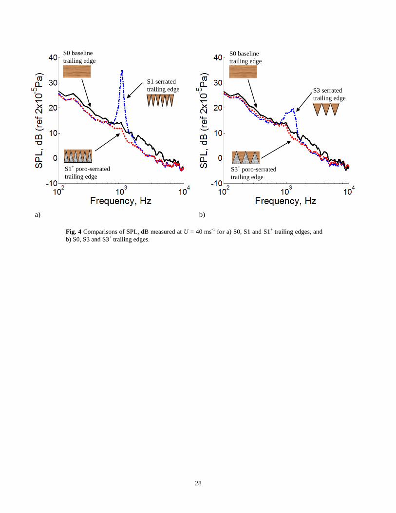
28
Fig. 4 Comparisons of SPL, dB measured at U = 40 ms-1
for a) S0, S1 and S1+ trailing edges, and
b) S0, S3 and S3+ trailing edges.
a) b)
S0 baseline
trailing edge
S1 serrated
trailing edge
S1+ poro-serrated
trailing edge
S0 baseline
trailing edge
S3 serrated
trailing edge
S3+ poro-serrated
trailing edge
29
Fig. 5 Comparisons of the near wake fluctuating velocity power spectral density
(PSD) measured at x/C = 1.03 and U = 40 ms-1
for a) S0, b) S1, and c) S1+ trailing
edges. All PSD maps correspond to f = 1 kHz.
z
x
y
root
tip
root
z = -5 mm
tip
z = -2.5 mm
z = 0
z = 2.5 mm
z = 5 mm
tip
Flow
direction
z
x
y
root
tip
root
z = -5 mm
tip
z = -2.5 mm
z = 0
z = 2.5 mm
z = 5 mm
tip
Flow
direction
z
x
y
a) b) c)
dB / Hz
30
Fig. 6 Comparisons of near wake , dB measured at x/C = 1.03 and U = 40 ms-1
for S0, S1, and S1+
trailing edges at various z locations.
a) z = 0 mm
(sawtooth tip) b) z = 1 mm c) z = 2.5 mm
(sawtooth root)
d) z = 4 mm e) z = 5 mm
(sawtooth tip)
S0
S1 – –
S1+
S0
S1 – –
S1+
S0
S1 – –
S1+
S0
S1 – –
S1+
S0
S1 – –
S1+
31
Fig. 7 Color maps of the SPL, dB produced by a) S1 serrated trailing edge and b) S1+ poro-serrated
trailing edge. The velocity resolution is 2 ms-1
.
a) b)
SPL,
dB
St = 0.18
St = 0.12
32
Fig. 8 Color maps of the SPL, dB produced by a) S3 serrated trailing edge and b) S3+ poro-serrated
trailing edge. The velocity resolution is 2 ms-1
.
a) b)
SPL,
dB
St = 0.22
St = 0.12
33
Fig. 9 Comparisons of the beamformer maps at f = 2.3 kHz at U = 40 ms-1
for a) baseline S0 straight
trailing edge and b) S1+ poro-serrated trailing edge.
50
mm
50 mm
z
x S1
+ poro-serrated
trailing edge
Leading edge
S0, straight
trailing edge
Flow direction Flow direction
SPL, dB
52
43
46
49
a) b)

34
Fig. 10 Color maps of the SPL, dB produced by a) S3 serrated trailing edge and b) S3+ poro-
serrated trailing edge. This repeatability test was performed at the ISVR anechoic chamber. The
velocity resolution is 2 ms-1
.
SPL,
dB
a) b)
St = 0.22
St = 0.12
35
Fig. 11 Color map of the SPL, dB produced by the S3– “inversed” poro-serrated trailing
edge. The velocity resolution is 2 ms-1
.
SPL,
dB
36
Fig. 12 Color map of the SPL, dB produced by the SP partially porous trailing edge. The
velocity resolution is 2 ms-1
.
SPL,
dB
St = 0.18
St = 0.15
37
Fig. 13 Color map of the SPL, dB produced by the S3 poro-serrated trailing edge. The
velocity resolution is 2 ms-1
.
SPL,
dB
38
Fig. 14 Comparisons of the SPL, dB measured at U = 40 ms-1
between the baseline S0 trailing edge and the
S3 poro-serrated trailing edge with a) high-, b) medium-, and c) light-density brush bundles that fill the gaps
between adjacent members of the sawtooth.
a) b) c) High-density brush bundle Medium-density brush bundle
( 60% of the high density)
Light-density brush bundle
( 30% of the high density)
S0
S3
S0
S3
S0
S3
39
Fig. 15 a) Comparisons between the S3+ and S3
++ poro-serrated trailing edges in a) SPL, dB at U = 36
ms-1
and b) Color map of SPL (S3+ – S3
++), dB at different frequency and velocity. The velocity
resolution is 2 ms-1
.
a) b)
SPL,
dB
S0 baseline
trailing edge
S3++
trailing edge
(sawtooth gaps filled
with Melamine foam)
S3+ trailing edge (sawtooth
gaps filled with porous
nickel-chromium foam)
40
Fig. 16 Comparisons of a) CL, b) CD and c) CL/CD against produced by S0 trailing
edge (baseline) and S1+ and S3
+ poro-serrated trailing edges at U = 30 ms
-1
a) b)
c)
41
Fig. 17 Schematics of locations of hot-film sensors HF1 and HF2 relative to a) S0
trailing edge and b) S3+ poro-serrated trailing edge. Drawings are not to scale.
a)
Flow
direction
b)
Sawtooth
tips
Sawtooth
roots
Porous
metal foams
Solid
sawtooth
Solid
straight TE
(HF1_S0) (HF2_S0) (HF1_S3
+) (HF2_ S3+)
z
x
42
Fig. 18 Schematics showing a surface-mounted hot-film sensor (Dantec, type 55R47)
used in the current work. All units are in millimeters.
1.5
Sensing element
Removed
Kapton foil
Flow direction
0.1 0.9 8
16
Gold-plated leads
43
Fig. 19 Comparisons of the near wall fluctuating power spectral densities (, dB) measured
by hot-film sensors at U = 40 ms-1
.
a) b)
HF1_S0 HF2_S0
HF1_S3+ HF2_S3
+
44
Fig. 20 Color maps of a) 1 and b) 2 [both calculated by Eq. (3)], and c) SPL produced by S3+ poro-
serrated trailing edge [calculated by Eq. (2)].
Zone I
Zone II
Zone III
i
dB
1_S0 1_S3+ 2_S0 2_S3
+
a) b)
Zone I
Zone II
Zone III
SPL,
dB
c)
45
Symbols Illustrations SPL (f, U)a,b
, dB
S3
G
rou
p A
S3+
S3
S3–
G
rou
p B
S3o
SP
Table 2 Summary of all noise performances in SPL, dB, for S3, S3+, S3
–, S3
,
S3o and SP trailing edge devices investigated in this study.
Zone I
Zone II
Zone III 20
5
1
0.1
Fre
q., k
Hz
20 40 60
U, ms-1
Zone I
Zone II
Zone III 20
5
1
0.1 F
req
., k
Hz
20 40 60
U, ms-1
Zone I
Zone II
Zone III 20
5
1
0.1
Fre
q., k
Hz
20 40 60
U, ms-1
Zone I
Zone II
Zone III 20
5
1
0.1
Fre
q., k
Hz
20 40 60
U, ms-1
Zone I
Zone II
Zone III 20
5
1
0.1
Fre
q., k
Hz
20 40 60
U, ms-1
Zone I
Zone II
Zone III 20
5
1
0.1
Fre
q., k
Hz
20 40 60
U, ms-1
a. Positive level of SPL denotes noise reduction, and vice versa.
b. The three zones (I, II and III) in the SPL maps were identified from the 2
contours in Fig. 20b.