portable ultrasonic flow measurement of liquids - flexim.com · technical specification fluxus f601...
TRANSCRIPT

Technical specification
FLUXUS F601
TSFLUXUS_F601V2-3US_Lus, 2019-05-01
Features
• Precise bidirectional and highly dynamic flow measurement with the non-invasive clamp-on technology
• High precision at fast and slow flow rates, high temperature and zero point stability
• Portable, easy-to-use flow transmitter with 2 flow channels, multiple inputs/outputs, an integrated data logger with a serial interface
• Water and dust-tight (NEMA 4); resistant against oil, many liq-uids and dirt
• Li-Ion battery provides up to 25 hours of measurement opera-tion
• Automatic loading of calibration data and transducer detection for a fast and easy set-up (less than 5 min), providing precise and long-term stable results
• User-friendly design
• Transducers available for a wide range of inner pipe diameters and fluid temperatures ( )
• Probe for wall thickness measurement available
• Robust, water-tight (NEMA 4) transport case with comprehen-sive accessories
• HybridTrek automatically switches between transit time and NoiseTrek mode of measurement when high particulate flows are encountered
• QuickFix for fast mounting of the flow transmitter in difficult conditions
• Measurement is unaffected by fluid density, viscosity and solid content (max. 10 % of volume)
Applications
Designed for the following industries:
• Chemical industry
• Water and wastewater industry
• Oil and gas industry
• Cooling systems and air conditioners
• Facility management
• Aviation industry
-328 to +1112 °F
FLUXUS F601
Measurement with transducers mounted with mounting frames and flow transmitter fixed to the pipe with the QuickFix pipe mounting fixture
Measurement equipment in transport case
Portable ultrasonic flow measurement of liquids
Portable instrument for non-invasive, quick ultrasonic flow measurement with clamp-on technology for all types of piping
FLUXUS F601 Technical specification
2019-05-01, TSFLUXUS_F601V2-3US_Lus2
Table of contents
Function . . . . . . . . . . . . . . . . . . . . . . . . . . . . . . . . . . . . . . . . . . . . . . . . . . . . . . . . . . . . . . . . . . . . . . . . . . . . . . . . . . . . . . . 3Measurement principle . . . . . . . . . . . . . . . . . . . . . . . . . . . . . . . . . . . . . . . . . . . . . . . . . . . . . . . . . . . . . . . . . . . . . . . . . . . . . 3Calculation of volumetric flow rate . . . . . . . . . . . . . . . . . . . . . . . . . . . . . . . . . . . . . . . . . . . . . . . . . . . . . . . . . . . . . . . . . . . . 3Number of sound paths . . . . . . . . . . . . . . . . . . . . . . . . . . . . . . . . . . . . . . . . . . . . . . . . . . . . . . . . . . . . . . . . . . . . . . . . . . . . 4Typical measurement setup . . . . . . . . . . . . . . . . . . . . . . . . . . . . . . . . . . . . . . . . . . . . . . . . . . . . . . . . . . . . . . . . . . . . . . . . . 5
Transmitter . . . . . . . . . . . . . . . . . . . . . . . . . . . . . . . . . . . . . . . . . . . . . . . . . . . . . . . . . . . . . . . . . . . . . . . . . . . . . . . . . . . . . 6Technical data . . . . . . . . . . . . . . . . . . . . . . . . . . . . . . . . . . . . . . . . . . . . . . . . . . . . . . . . . . . . . . . . . . . . . . . . . . . . . . . . . . . 6Dimensions. . . . . . . . . . . . . . . . . . . . . . . . . . . . . . . . . . . . . . . . . . . . . . . . . . . . . . . . . . . . . . . . . . . . . . . . . . . . . . . . . . . . . . 7Standard scope of supply. . . . . . . . . . . . . . . . . . . . . . . . . . . . . . . . . . . . . . . . . . . . . . . . . . . . . . . . . . . . . . . . . . . . . . . . . . . 8Adapters . . . . . . . . . . . . . . . . . . . . . . . . . . . . . . . . . . . . . . . . . . . . . . . . . . . . . . . . . . . . . . . . . . . . . . . . . . . . . . . . . . . . . . . . 8Example for the equipment of a transport case . . . . . . . . . . . . . . . . . . . . . . . . . . . . . . . . . . . . . . . . . . . . . . . . . . . . . . . . . . 9
Transducers . . . . . . . . . . . . . . . . . . . . . . . . . . . . . . . . . . . . . . . . . . . . . . . . . . . . . . . . . . . . . . . . . . . . . . . . . . . . . . . . . . . 10Transducer selection . . . . . . . . . . . . . . . . . . . . . . . . . . . . . . . . . . . . . . . . . . . . . . . . . . . . . . . . . . . . . . . . . . . . . . . . . . . . . 10Transducer order code . . . . . . . . . . . . . . . . . . . . . . . . . . . . . . . . . . . . . . . . . . . . . . . . . . . . . . . . . . . . . . . . . . . . . . . . . . . . 11Technical data . . . . . . . . . . . . . . . . . . . . . . . . . . . . . . . . . . . . . . . . . . . . . . . . . . . . . . . . . . . . . . . . . . . . . . . . . . . . . . . . . . 12
Transducer mounting fixture. . . . . . . . . . . . . . . . . . . . . . . . . . . . . . . . . . . . . . . . . . . . . . . . . . . . . . . . . . . . . . . . . . . . . . 14
Coupling materials for transducers . . . . . . . . . . . . . . . . . . . . . . . . . . . . . . . . . . . . . . . . . . . . . . . . . . . . . . . . . . . . . . . . 17
Connection systems . . . . . . . . . . . . . . . . . . . . . . . . . . . . . . . . . . . . . . . . . . . . . . . . . . . . . . . . . . . . . . . . . . . . . . . . . . . . 18
Clamp-on temperature probe (optional). . . . . . . . . . . . . . . . . . . . . . . . . . . . . . . . . . . . . . . . . . . . . . . . . . . . . . . . . . . . . 19Technical data . . . . . . . . . . . . . . . . . . . . . . . . . . . . . . . . . . . . . . . . . . . . . . . . . . . . . . . . . . . . . . . . . . . . . . . . . . . . . . . . . . 19Fixation. . . . . . . . . . . . . . . . . . . . . . . . . . . . . . . . . . . . . . . . . . . . . . . . . . . . . . . . . . . . . . . . . . . . . . . . . . . . . . . . . . . . . . . . 20
Wall thickness measurement (optional). . . . . . . . . . . . . . . . . . . . . . . . . . . . . . . . . . . . . . . . . . . . . . . . . . . . . . . . . . . . . 21Technical data . . . . . . . . . . . . . . . . . . . . . . . . . . . . . . . . . . . . . . . . . . . . . . . . . . . . . . . . . . . . . . . . . . . . . . . . . . . . . . . . . . 21
Technical specification FLUXUS F601
3TSFLUXUS_F601V2-3US_Lus, 2019-05-01
Function
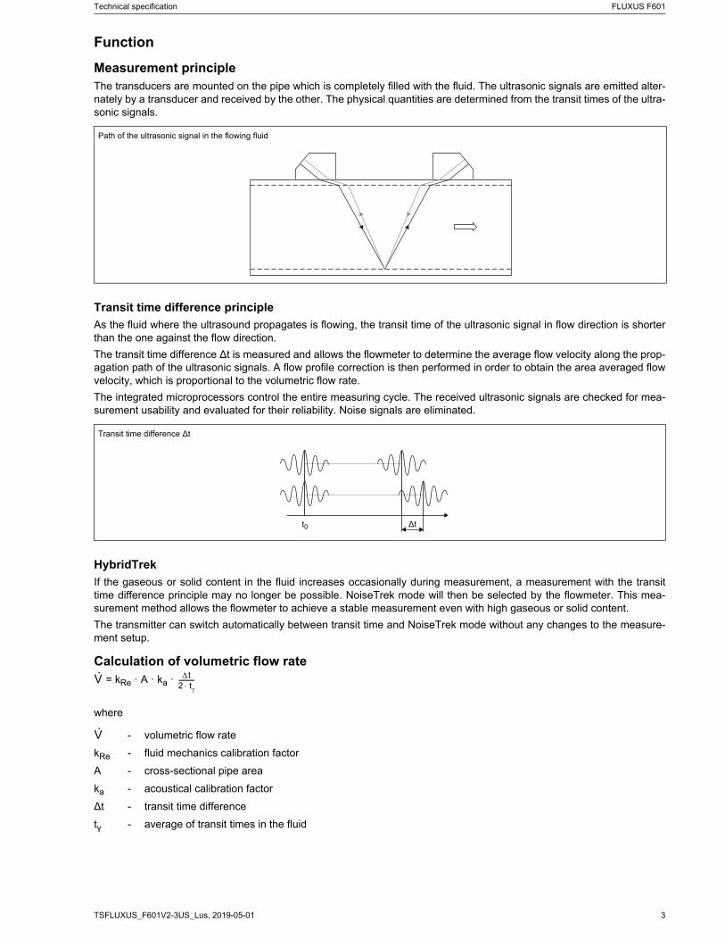
Measurement principleThe transducers are mounted on the pipe which is completely filled with the fluid. The ultrasonic signals are emitted alter-nately by a transducer and received by the other. The physical quantities are determined from the transit times of the ultra-sonic signals.
Transit time difference principle
As the fluid where the ultrasound propagates is flowing, the transit time of the ultrasonic signal in flow direction is shorterthan the one against the flow direction.
The transit time difference ∆t is measured and allows the flowmeter to determine the average flow velocity along the prop-agation path of the ultrasonic signals. A flow profile correction is then performed in order to obtain the area averaged flowvelocity, which is proportional to the volumetric flow rate.
The integrated microprocessors control the entire measuring cycle. The received ultrasonic signals are checked for mea-surement usability and evaluated for their reliability. Noise signals are eliminated.
HybridTrek
If the gaseous or solid content in the fluid increases occasionally during measurement, a measurement with the transittime difference principle may no longer be possible. NoiseTrek mode will then be selected by the flowmeter. This mea-surement method allows the flowmeter to achieve a stable measurement even with high gaseous or solid content.
The transmitter can switch automatically between transit time and NoiseTrek mode without any changes to the measure-ment setup.
Calculation of volumetric flow rate = kRe · A · ka ·
where
Path of the ultrasonic signal in the flowing fluid
Transit time difference ∆t
- volumetric flow rate
kRe - fluid mechanics calibration factor
A - cross-sectional pipe area
ka - acoustical calibration factor
∆t - transit time difference
tγ - average of transit times in the fluid
∆tt0
V· t2 t-----------
V·
FLUXUS F601 Technical specification
2019-05-01, TSFLUXUS_F601V2-3US_Lus4
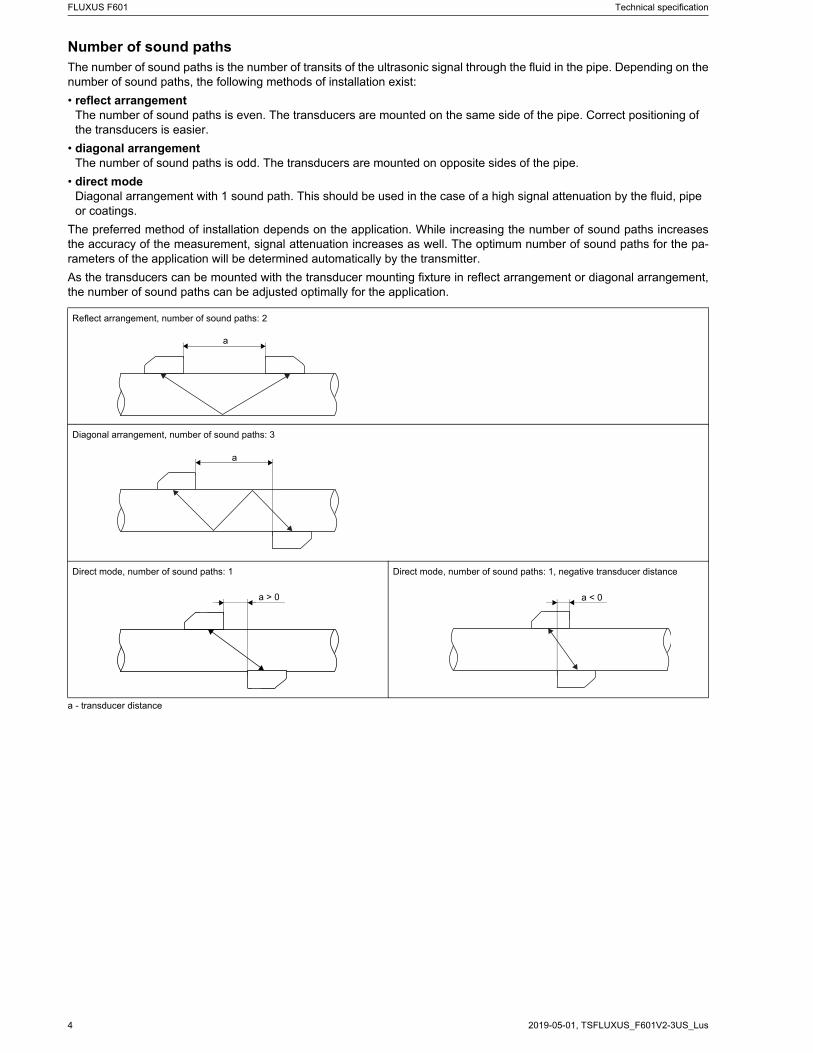
Number of sound pathsThe number of sound paths is the number of transits of the ultrasonic signal through the fluid in the pipe. Depending on thenumber of sound paths, the following methods of installation exist:
• reflect arrangementThe number of sound paths is even. The transducers are mounted on the same side of the pipe. Correct positioning of the transducers is easier.
• diagonal arrangementThe number of sound paths is odd. The transducers are mounted on opposite sides of the pipe.
• direct modeDiagonal arrangement with 1 sound path. This should be used in the case of a high signal attenuation by the fluid, pipe or coatings.
The preferred method of installation depends on the application. While increasing the number of sound paths increasesthe accuracy of the measurement, signal attenuation increases as well. The optimum number of sound paths for the pa-rameters of the application will be determined automatically by the transmitter.
As the transducers can be mounted with the transducer mounting fixture in reflect arrangement or diagonal arrangement,the number of sound paths can be adjusted optimally for the application.
a - transducer distance
Reflect arrangement, number of sound paths: 2
Diagonal arrangement, number of sound paths: 3
Direct mode, number of sound paths: 1 Direct mode, number of sound paths: 1, negative transducer distance
a
a
a > 0 a < 0
Technical specification FLUXUS F601
5TSFLUXUS_F601V2-3US_Lus, 2019-05-01
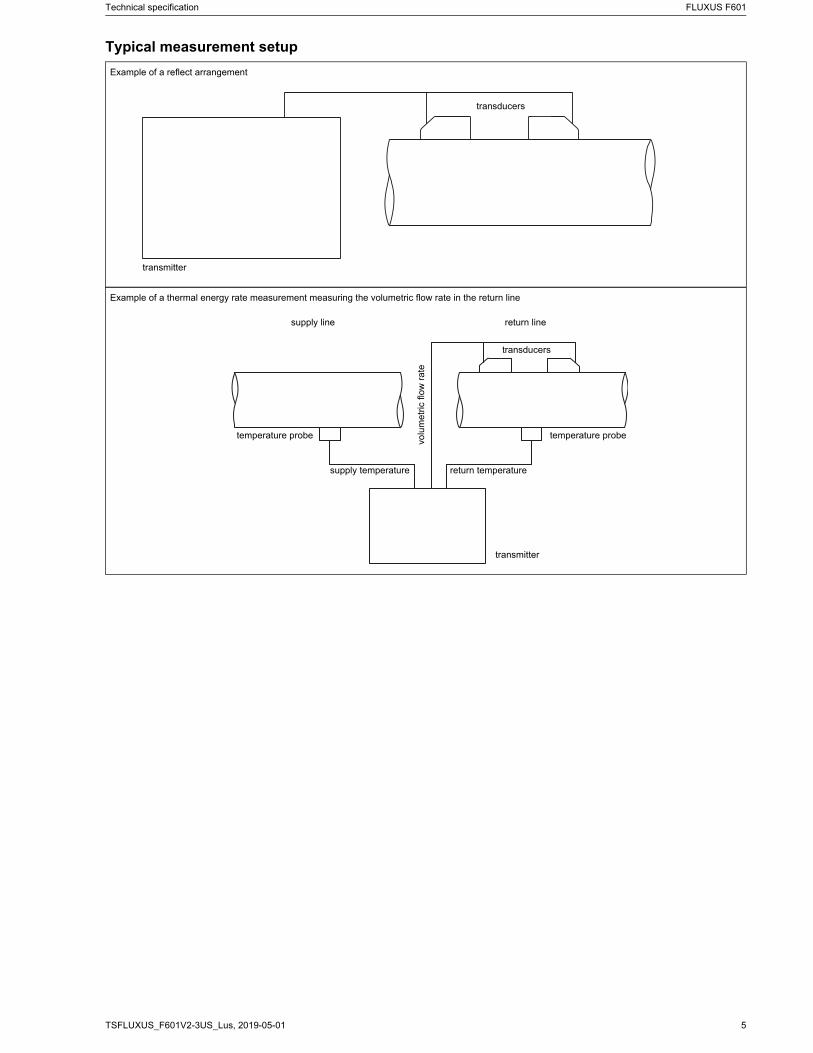
Typical measurement setup
Example of a reflect arrangement
Example of a thermal energy rate measurement measuring the volumetric flow rate in the return line
transducers
transmitter
transducers
transmitter
temperature probetemperature probe
supply line return line
volu
met
ric fl
ow
ra
te
supply temperature return temperature
FLUXUS F601 Technical specification
2019-05-01, TSFLUXUS_F601V2-3US_Lus6
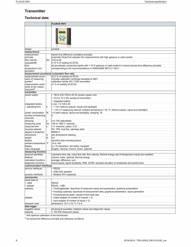
Transmitter
Technical data
FLUXUS F601
design portablemeasurementmeasurement principle
transit time difference correlation principle,automatic NoiseTrek selection for measurements with high gaseous or solid content
flow velocity ft/s 0.03 to 82repeatability 0.15 % of reading ±0.02 ft/sfluid all acoustically conductive liquids with < 10 % gaseous or solid content in volume (transit time difference principle)temperature com-pensation
corresponding to the recommendations in ANSI/ASME MFC-5.1-2011
measurement uncertainty (volumetric flow rate)measurement uncer-tainty of measuring system1
±0.3 % of reading ±0.02 ft/sincludes calibration certificate traceable to NISTcalibration facility ISO 17025 accredited
measurement uncer-tainty at the measu-ring point2
±1 % of reading ±0.02 ft/s
transmitterpower supply • 100 to 230 V/50 to 60 Hz (power supply unit)
• 10.5 to 15 V DC (socket at transmitter)
• integrated batteryintegrated battery Li-Ion, 7.2 V/6.2 Ah• operating time h • > 14 h (without outputs, inputs and backlight)
• > 25 h (1 measuring channel, ambient temperature > 50 °F, without outputs, inputs and backlight)power consumption W < 6 (with outputs, inputs and backlight), charging: 18number of measuring channels
2
damping s 0 to 100 (adjustable)measuring cycle Hz 100 to 1000 (1 channel)response time s 1 (1 channel), option: 0.07housing material PA, TPE, AutoTex, stainless steeldegree of protection NEMA 4dimensions in see dimensional drawingweight lb 4.6fixation QuickFix pipe mounting fixtureambient temperature °F 14 to 140display 2 x 16 characters, dot matrix, backlightmenu language English, German, French, Dutch, Spanishmeasuring functionsphysical quantities volumetric flow rate, mass flow rate, flow velocity, thermal energy rate (if temperature inputs are installed)totalizer volume, mass, optional: thermal energycalculation functions average, difference, sumdiagnostic functions sound speed, signal amplitude, SNR, SCNR, standard deviation of amplitudes and transit timescommunication interfacesservice interfaces • RS232
• USB (with adapter)process interfaces • Modbus RTU (optional)accessoriesserial data kit• сable RS232• adapter RS232 - USBsoftware • FluxDiagReader: download of measured values and parameters, graphical presentation
• FluxDiag (optional): download of measurement data, graphical presentation, report generation
• FluxSubstanceLoader: upload of fluid data setsadapter • output adapter (if number of outputs > 4)
• input adapter (if number of inputs > 2)transport case dimensions: 19.7 x 15.7 x 7.5 indata loggerloggable values all physical quantities, totalized values and diagnostic valuescapacity > 100 000 measured values1 with aperture calibration of the transducers2 for transit time difference principle and reference conditions
Technical specification FLUXUS F601
7TSFLUXUS_F601V2-3US_Lus, 2019-05-01
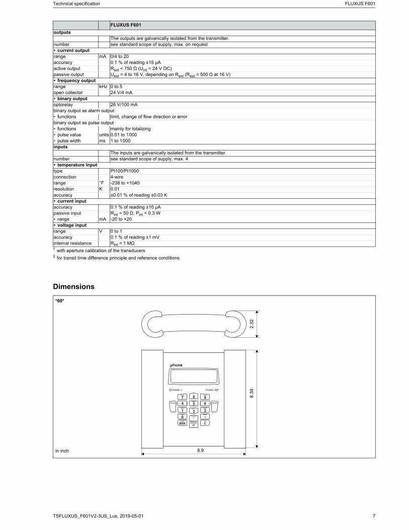
Dimensions
outputsThe outputs are galvanically isolated from the transmitter.
number see standard scope of supply, max. on request• current outputrange mA 0/4 to 20accuracy 0.1 % of reading ±15 μAactive output Rext < 750 Ω (Uint = 24 V DC)passive output Uext = 4 to 16 V, depending on Rext (Rext < 500 Ω at 16 V)• frequency outputrange kHz 0 to 5open collector 24 V/4 mA• binary outputoptorelay 26 V/100 mAbinary output as alarm output• functions limit, change of flow direction or errorbinary output as pulse output• functions mainly for totalizing• pulse value units 0.01 to 1000• pulse width ms 1 to 1000inputs
The inputs are galvanically isolated from the transmitter.number see standard scope of supply, max. 4• temperature inputtype Pt100/Pt1000connection 4-wirerange °F -238 to +1040resolution K 0.01accuracy ±0.01 % of reading ±0.03 K• current inputaccuracy 0.1 % of reading ±10 μApassive input Rint = 50 Ω, Pint < 0.3 W• range mA -20 to +20• voltage inputrange V 0 to 1accuracy 0.1 % of reading ±1 mVinternal resistance Rint = 1 MΩ
*60*
FLUXUS F601
1 with aperture calibration of the transducers2 for transit time difference principle and reference conditions
CHANNEL BCHANNEL A
BATTERY
1 20
4 5 67
SNAPQ- Q+
MUX
NEXT
9DISP
3DISP
–MODEFAST
.LIGHT
3x OFF
3x QOFF
8QON
ENTER ENTER
BRKON
C
8.9
2.3
28
.39
in inch
FLUXUS F601 Technical specification
2019-05-01, TSFLUXUS_F601V2-3US_Lus8
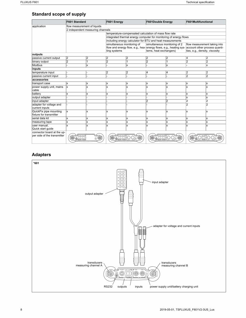
Standard scope of supply
Adapters
F601 Standard F601 Energy F601Double Energy F601Multifunctional
application flow measurement of liquids2 independent measuring channels
temperature-compensated calculation of mass flow rateintegrated thermal energy computer for monitoring of energy flowsincluding energy calculator for BTU and heat measurementssimultaneous monitoring of flow and energy flow, e.g., hea-ting systems
simultaneous monitoring of 2 energy flows, e.g., heating sys-tems, heat exchangers)
flow measurement taking into account other process quanti-ties, e.g., density, viscosity
outputspassive current output 2 2 2 2 2 2 4 2binary output 2 1 2 1 2 1 2 2Modbus - x - x - x - xinputstemperature input - - 2 2 4 4 2 2passive current input - - - - - - 2 2accessoriestransport case x x x x x x x xpower supply unit, mains cable
x x x x x x x x
battery x x x x x x x xoutput adapter - - - - - - x xinput adapter - - - - 2 2 2 2adapter for voltage and current inputs
- - - - - - 2 2
QuickFix pipe mounting fixture for transmitter
x x x x x x x x
serial data kit x x x x x x x xmeasuring tape x x x x x x x xuser manual,Quick start guide
x x x x x x x x
connector board at the up-per side of the transmitter
*601
output adapter
input adapter
adapter for voltage and current inputs
transducersmeasuring channel A
outputs inputs
transducersmeasuring channel B
power supply unit/battery charging unitRS232
Technical specification FLUXUS F601
9TSFLUXUS_F601V2-3US_Lus, 2019-05-01
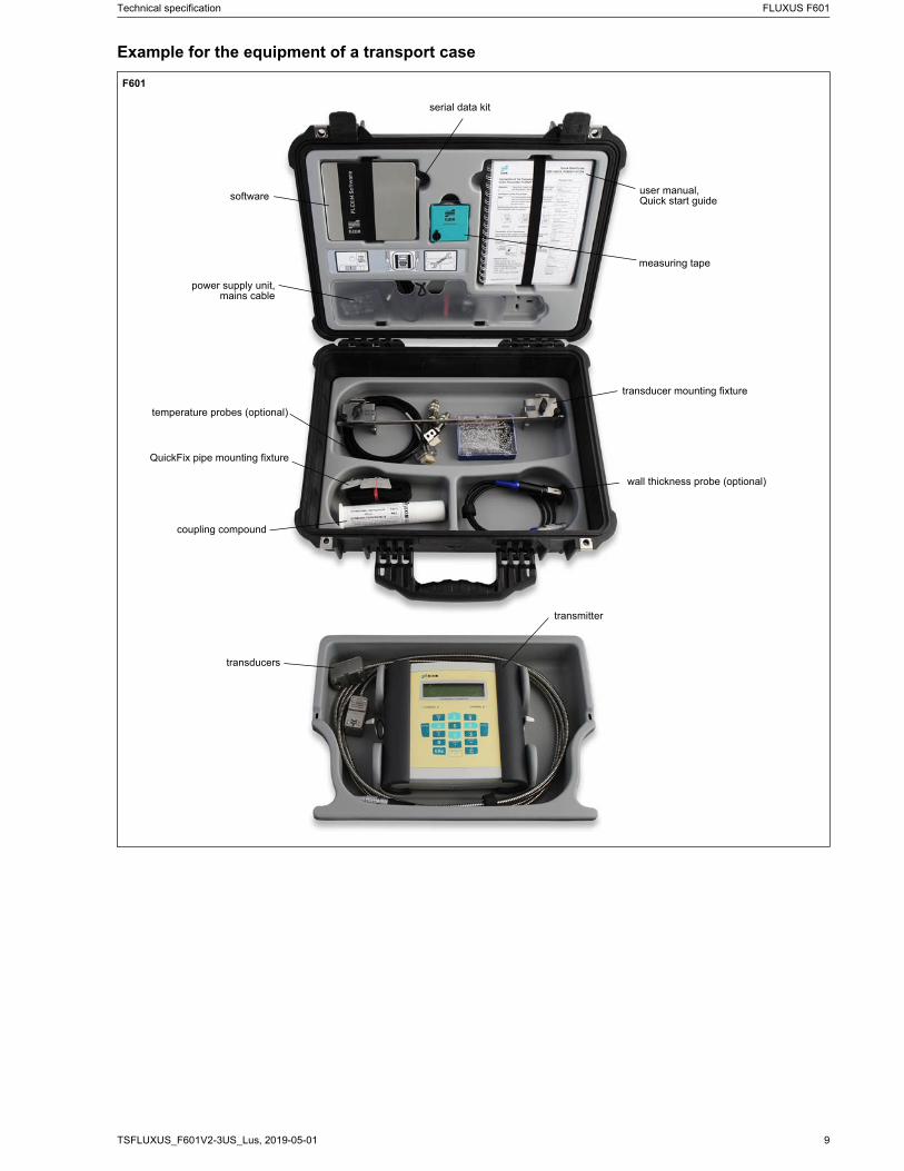
Example for the equipment of a transport case
F601
software
power supply unit,mains cable
transducer mounting fixture
measuring tape
transmitter
transducers
user manual,Quick start guide
coupling compound
wall thickness probe (optional)
QuickFix pipe mounting fixture
temperature probes (optional)
serial data kit
FLUXUS F601 Technical specification
2019-05-01, TSFLUXUS_F601V2-3US_Lus10
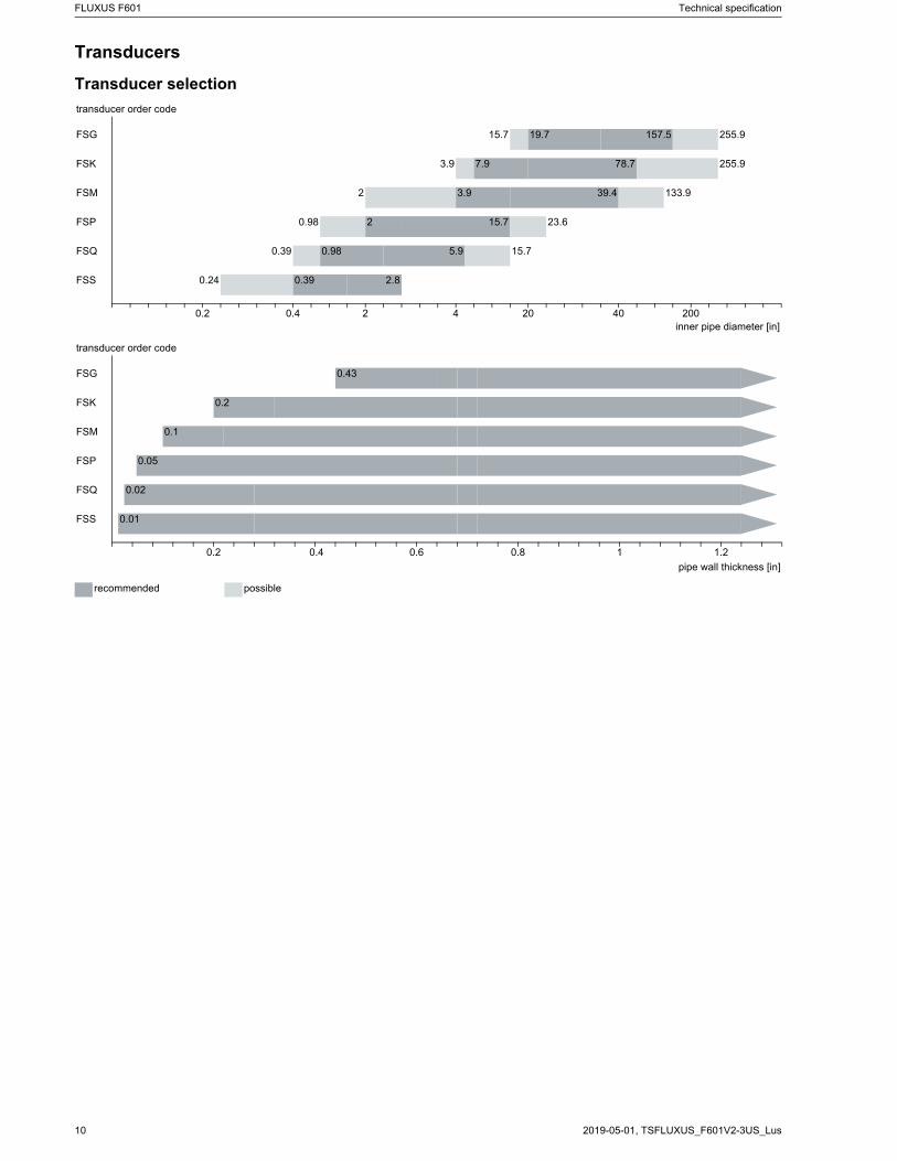
Transducers
Transducer selection
transducer order code
FSG 15.7 19.7 157.5 255.9
FSK 3.9 7.9 78.7 255.9
FSM 2 3.9 39.4 133.9
FSP 0.98 2 15.7 23.6
FSQ 0.39 0.98 5.9 15.7
FSS 0.24 0.39 2.8
0.2 0.4 2 4 20 40 200inner pipe diameter [in]
transducer order code
FSG 0.43
FSK 0.2
FSM 0.1
FSP 0.05
FSQ 0.02
FSS 0.01
0.2 0.4 0.6 0.8 1 1.2
pipe wall thickness [in]
recommended possible
Technical specification FLUXUS F601
11TSFLUXUS_F601V2-3US_Lus, 2019-05-01
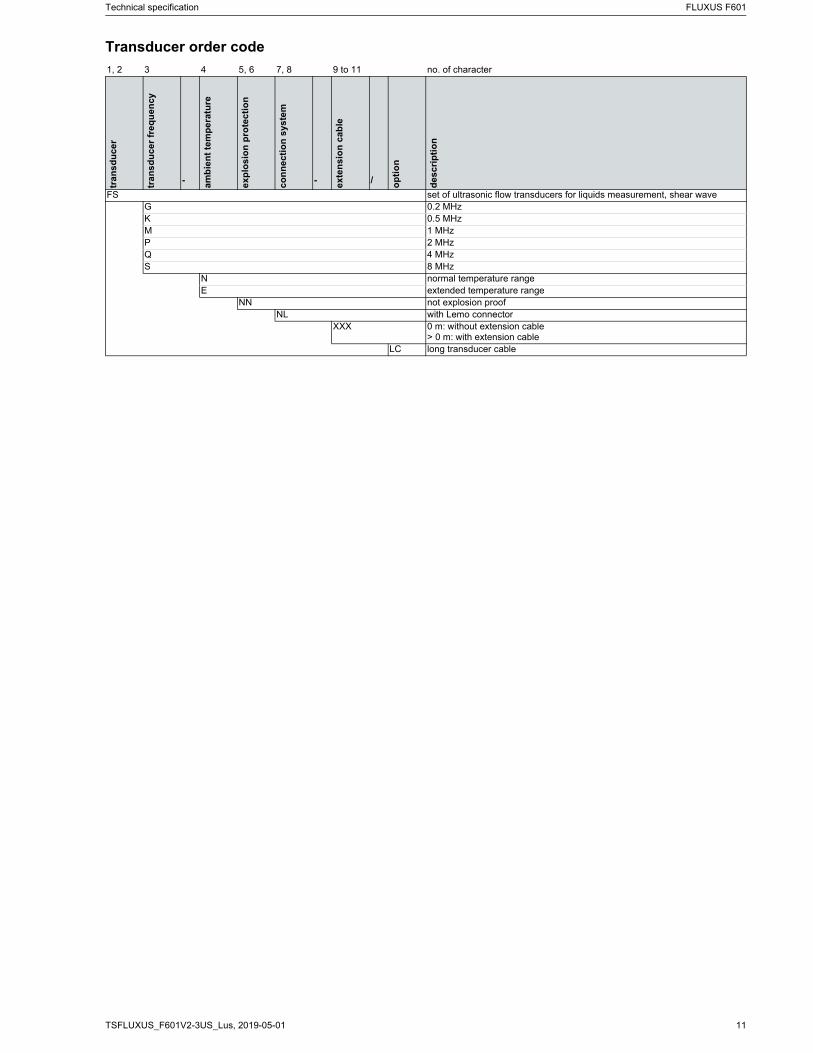
Transducer order code
1, 2 3 4 5, 6 7, 8 9 to 11 no. of character
tra
ns
du
ce
r
tra
ns
du
ce
r fr
equ
ency
- am
bie
nt
tem
pe
ratu
re
exp
losi
on
pro
tec
tio
n
co
nn
ec
tio
n s
yste
m
- ex
ten
sio
n c
ab
le
/ op
tio
n
de
sc
rip
tio
n
FS set of ultrasonic flow transducers for liquids measurement, shear waveG 0.2 MHzK 0.5 MHzM 1 MHzP 2 MHzQ 4 MHzS 8 MHz
N normal temperature rangeE extended temperature range
NN not explosion proofNL with Lemo connector
XXX 0 m: without extension cable> 0 m: with extension cable
LC long transducer cable
FLUXUS F601 Technical specification
2019-05-01, TSFLUXUS_F601V2-3US_Lus12
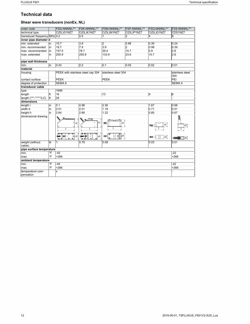
Technical data
Shear wave transducers (nonEx, NL)
order code FSG-NNNNL/** FSK-NNNNL/** FSM-NNNNL/** FSP-NNNNL/** FSQ-NNNNL/** FSS-NNNNL/**technical type C(DL)G1NZ7 C(DL)K1NZ7 C(DL)M1NZ7 C(DL)P1NZ7 C(DL)Q1NZ7 CDS1NZ7transducer frequency MHz 0.2 0.5 1 2 4 8inner pipe diameter dmin. extended in 15.7 3.9 2 0.98 0.39 0.24min. recommended in 19.7 7.9 3.9 2 0.98 0.39max. recommended in 157.5 78.7 39.4 15.7 5.9 2.8max. extended in 255.9 255.9 133.9 23.6 15.7 2.8
pipe wall thicknessmin. in 0.43 0.2 0.1 0.05 0.02 0.01materialhousing PEEK with stainless steel cap 304 stainless steel 304 stainless steel
304contact surface PEEK PEEK PEIdegree of protection NEMA 6 NEMA 4transducer cabletype 1699length ft 16 13 9 6length (***-*****/LC) ft 29 -dimensionslength l in 5.1 4.98 2.36 1.67 0.98width b in 2.01 2.01 1.18 0.71 0.51height h in 2.64 2.66 1.32 0.85 0.67dimensional drawing
weight (without cable)
lb 1 0.79 0.08 0.03 0.01
pipe surface temperaturemin. °F -40 -22max. °F +266 +266ambient temperaturemin. °F -40 -22max. °F +266 +266temperature com-pensation
x -
l
hb
l
hb
l
hb
l
hb
l
bh
Technical specification FLUXUS F601
13TSFLUXUS_F601V2-3US_Lus, 2019-05-01
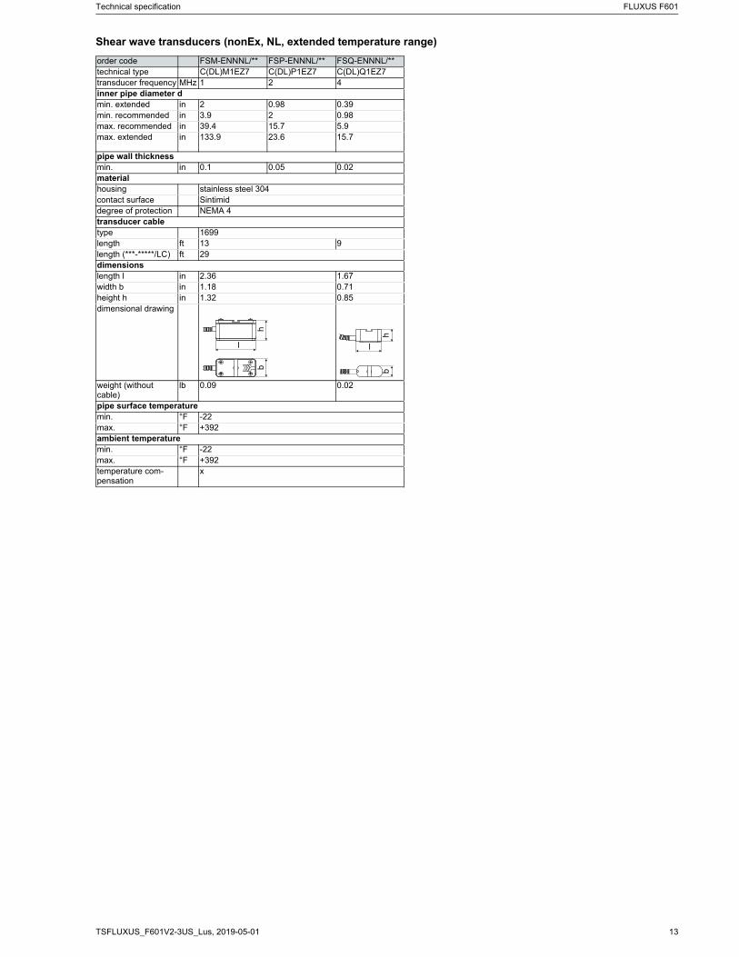
Shear wave transducers (nonEx, NL, extended temperature range)
order code FSM-ENNNL/** FSP-ENNNL/** FSQ-ENNNL/**technical type C(DL)M1EZ7 C(DL)P1EZ7 C(DL)Q1EZ7transducer frequency MHz 1 2 4inner pipe diameter dmin. extended in 2 0.98 0.39min. recommended in 3.9 2 0.98max. recommended in 39.4 15.7 5.9max. extended in 133.9 23.6 15.7
pipe wall thicknessmin. in 0.1 0.05 0.02materialhousing stainless steel 304contact surface Sintimiddegree of protection NEMA 4transducer cabletype 1699length ft 13 9length (***-*****/LC) ft 29dimensionslength l in 2.36 1.67width b in 1.18 0.71height h in 1.32 0.85dimensional drawing
weight (without cable)
lb 0.09 0.02
pipe surface temperaturemin. °F -22max. °F +392ambient temperaturemin. °F -22max. °F +392temperature com-pensation
x
l
hb
l
hb
FLUXUS F601 Technical specification
2019-05-01, TSFLUXUS_F601V2-3US_Lus14
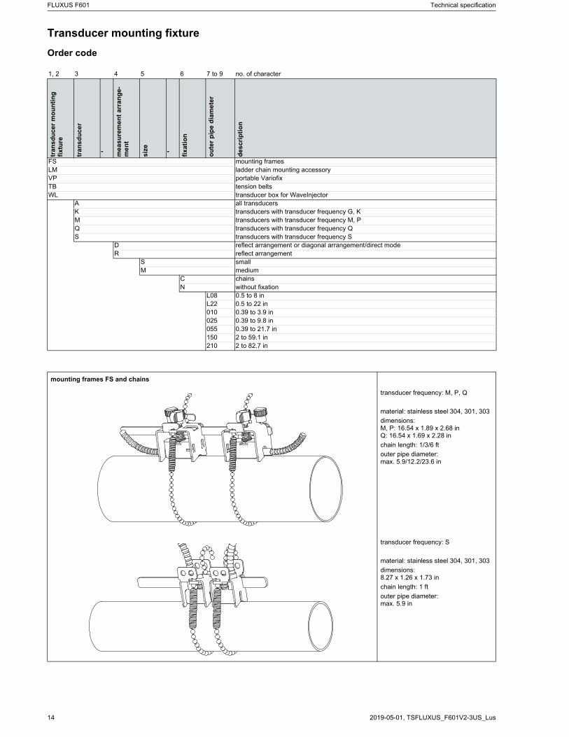
Transducer mounting fixture
Order code
1, 2 3 4 5 6 7 to 9 no. of character
tran
sdu
cer
mo
un
tin
g
fix
ture
tra
ns
du
ce
r
- mea
su
rem
ent
arr
an
ge
-m
ent
siz
e- fi
xa
tio
n
ou
ter
pip
e d
iam
ete
r
de
scr
ipti
on
FS mounting framesLM ladder chain mounting accessoryVP portable VariofixTB tension beltsWL transducer box for WaveInjector
A all transducersK transducers with transducer frequency G, KM transducers with transducer frequency M, PQ transducers with transducer frequency QS transducers with transducer frequency S
D reflect arrangement or diagonal arrangement/direct modeR reflect arrangement
S smallM medium
C chainsN without fixation
L08 0.5 to 8 inL22 0.5 to 22 in010 0.39 to 3.9 in025 0.39 to 9.8 in055 0.39 to 21.7 in150 2 to 59.1 in210 2 to 82.7 in
mounting frames FS and chains
transducer frequency: M, P, Q
material: stainless steel 304, 301, 303
dimensions:M, P: 16.54 x 1.89 x 2.68 inQ: 16.54 x 1.69 x 2.28 in
chain length: 1/3/6 ft
outer pipe diameter:max. 5.9/12.2/23.6 in
transducer frequency: S
material: stainless steel 304, 301, 303
dimensions:8.27 x 1.26 x 1.73 in
chain length: 1 ft
outer pipe diameter: max. 5.9 in
Technical specification FLUXUS F601
15TSFLUXUS_F601V2-3US_Lus, 2019-05-01
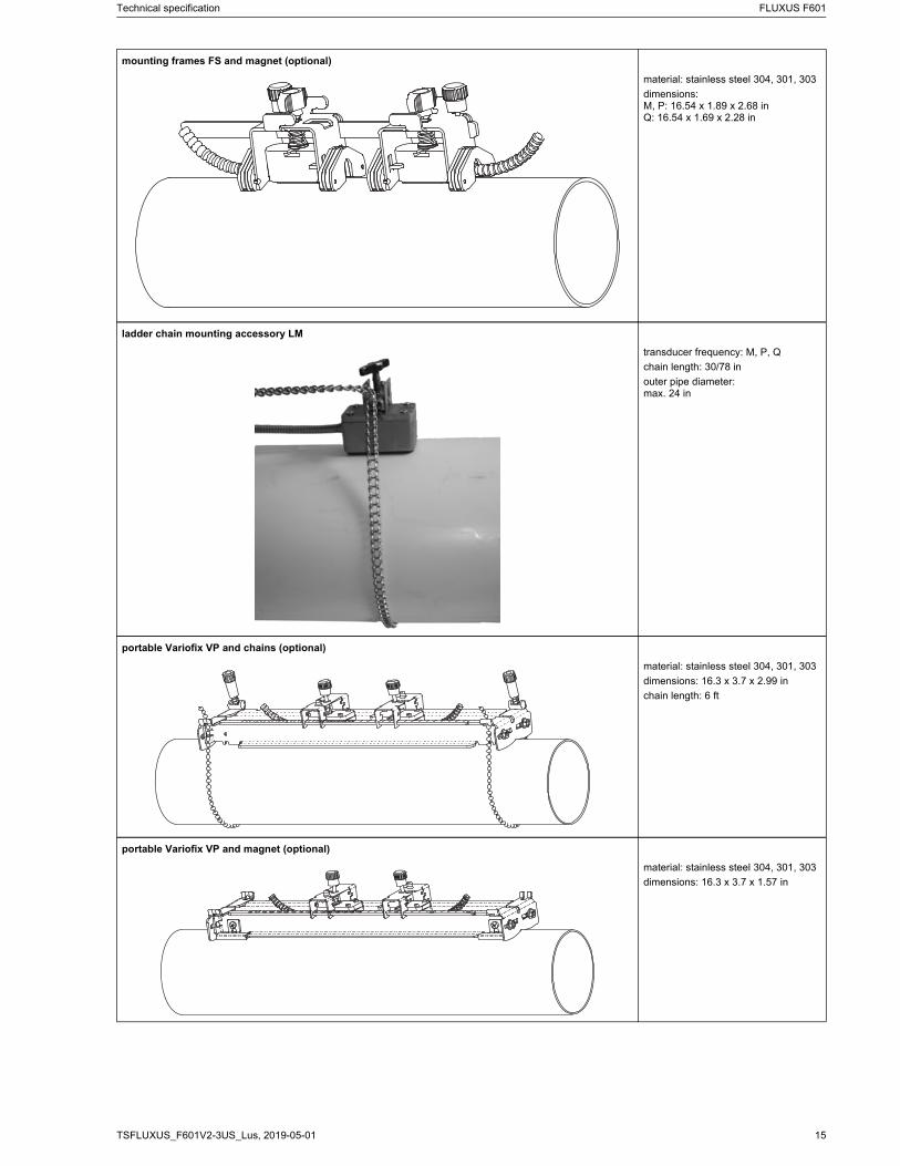
mounting frames FS and magnet (optional)
material: stainless steel 304, 301, 303
dimensions:M, P: 16.54 x 1.89 x 2.68 inQ: 16.54 x 1.69 x 2.28 in
ladder chain mounting accessory LM
transducer frequency: M, P, Q
chain length: 30/78 in
outer pipe diameter:max. 24 in
portable Variofix VP and chains (optional)
material: stainless steel 304, 301, 303
dimensions: 16.3 x 3.7 x 2.99 in
chain length: 6 ft
portable Variofix VP and magnet (optional)
material: stainless steel 304, 301, 303
dimensions: 16.3 x 3.7 x 1.57 in
FLUXUS F601 Technical specification
2019-05-01, TSFLUXUS_F601V2-3US_Lus16
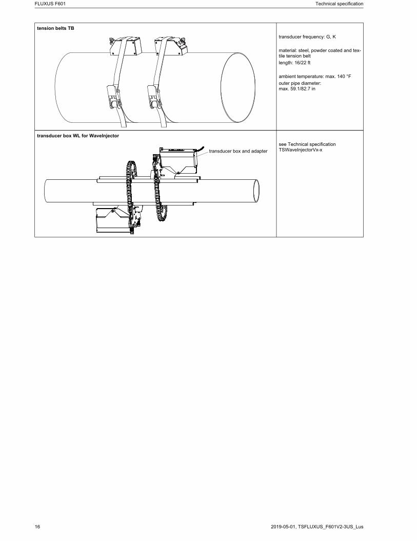
tension belts TB
transducer frequency: G, K
material: steel, powder coated and tex-tile tension belt
length: 16/22 ft
ambient temperature: max. 140 °F
outer pipe diameter:max. 59.1/82.7 in
transducer box WL for WaveInjector
see Technical specificationTSWaveInjectorVx-xtransducer box and adapter
Technical specification FLUXUS F601
17TSFLUXUS_F601V2-3US_Lus, 2019-05-01
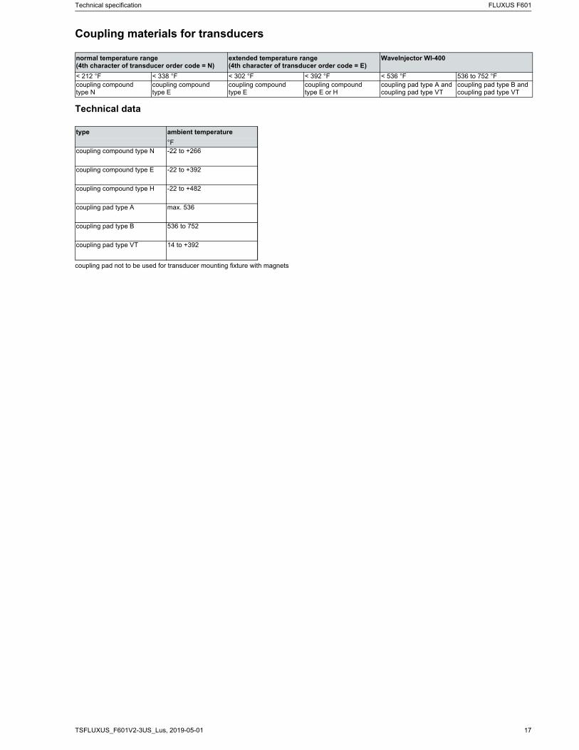
Coupling materials for transducers
Technical data
normal temperature range(4th character of transducer order code = N)
extended temperature range(4th character of transducer order code = E)
WaveInjector WI-400
< 212 °F < 338 °F < 302 °F < 392 °F < 536 °F 536 to 752 °Fcoupling compound type N
coupling compound type E
coupling compound type E
coupling compoundtype E or H
coupling pad type A and coupling pad type VT
coupling pad type B and coupling pad type VT
type ambient temperature
°Fcoupling compound type N -22 to +266
coupling compound type E -22 to +392
coupling compound type H -22 to +482
coupling pad type A max. 536
coupling pad type B 536 to 752
coupling pad type VT 14 to +392
coupling pad not to be used for transducer mounting fixture with magnets
FLUXUS F601 Technical specification
2019-05-01, TSFLUXUS_F601V2-3US_Lus18
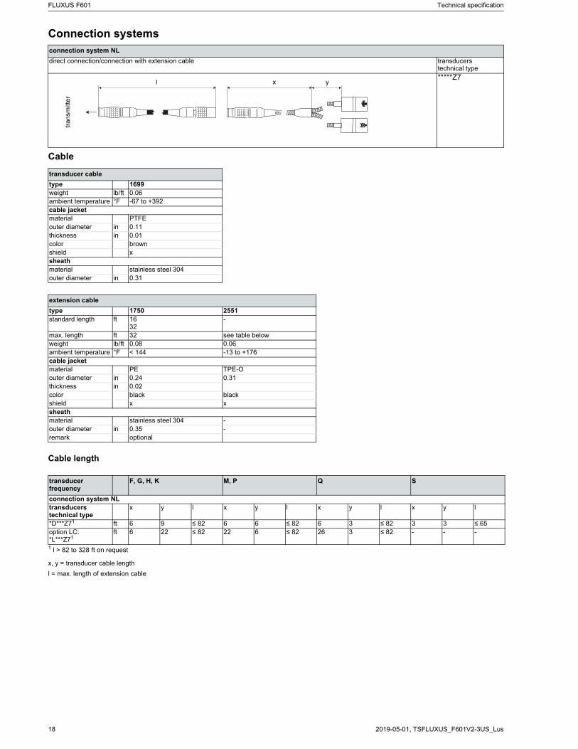
Connection systems
Cable
Cable length
connection system NL
direct connection/connection with extension cable transducerstechnical type*****Z7
transducer cable
type 1699weight lb/ft 0.06ambient temperature °F -67 to +392cable jacketmaterial PTFEouter diameter in 0.11thickness in 0.01color brownshield xsheathmaterial stainless steel 304outer diameter in 0.31
extension cable
type 1750 2551standard length ft 16
32-
max. length ft 32 see table belowweight lb/ft 0.08 0.06ambient temperature °F < 144 -13 to +176cable jacketmaterial PE TPE-Oouter diameter in 0.24 0.31thickness in 0.02color black blackshield x xsheathmaterial stainless steel 304 -outer diameter in 0.35 -remark optional
transducer frequency
F, G, H, K M, P Q S
connection system NLtransducerstechnical type
x y l x y l x y l x y l
*D***Z71 ft 6 9 ≤ 82 6 6 ≤ 82 6 3 ≤ 82 3 3 ≤ 65option LC:*L***Z71
ft 6 22 ≤ 82 22 6 ≤ 82 26 3 ≤ 82 - - -
1 l > 82 to 328 ft on request
x, y = transducer cable length
l = max. length of extension cable
tra
nsm
itte
r
l x y
Technical specification FLUXUS F601
19TSFLUXUS_F601V2-3US_Lus, 2019-05-01
Clamp-on temperature probe (optional)
Technical data
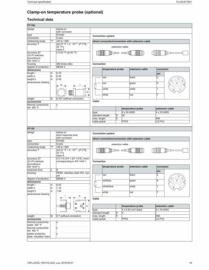
PT13N
design clamp-onwith connector
type Pt1000connection 4-wiremeasuring range °F -40 to +392accuracy T ±(0.27 °F + 2 . 10-3 . (|T [°F]| -
32 °F))class A
accuracy ∆T(2x Pt matched according to EN 1434-1)
≤ 0.03 °F (at 50 °F)
housing 360 brass alloydegree of protection NEMA 4dimensionslength l in 0.79width b in 0.59height h in 0.49dimensional drawing
weight lb 0.437 (without connector)accessoriesthermal conductivity foil 482 °F
x
PT13F
design clamp-onshort response time,with connector
type Pt1000connection 4-wiremeasuring range °F -58 to +482accuracy T ±(0.27 °F + 2 . 10-3 . (|T [°F]| -
32 °F))class A
accuracy ∆T(2x Pt matched according to EN 1434-1)
≤ 0.1 K (3 K < ∆T < 6 K), more corresponding to EN 1434-1
response time s 8housing PEEK, stainless steel 304, cop-
perdegree of protection NEMA 4dimensionslength l in 0.55width b in 1.18height h in 1.06dimensional drawing
weight lb 0.7 (without connector)accessoriesthermal conductivity paste 392 °F
x
thermal conductivity foil 482 °F
x
plastic protection plate, insulation foam
x
Connection system
Connection
Cable
direct connection/connection with extension cable
temperature probe extension cable connector
pin
red black 2
red green 6
white white 1
white red 7
temperature probe extension cable
type 4 x 24 AWG 4 x 18 AWGstandard length ft 20 -max. length ft - 656cable jacket PTFE LS PVC
extension cable
hlb
Connection system
Connection
Cable
direct connection/connection with extension cable
temperature probe extension cable connector
pin
red black 2
red/blue green 6
white/blue white 1
white red 7
temperature probe extension cable
type 4 x 0.25 mm² black 4 x 18 AWGstandard length ft 9 -max. length ft - 656cable jacket PTFE LS PVC
extension cable
h
bl

FLUXUS F601 Technical specification
2019-05-01, TSFLUXUS_F601V2-3US_Lus20
Fixation
tension strap PT13N
material: stainless steel 301, 410
ball chain PT13F
material: stainless steel 316L
length: 3 ft
Technical specification FLUXUS F601
21TSFLUXUS_F601V2-3US_Lus, 2019-05-01
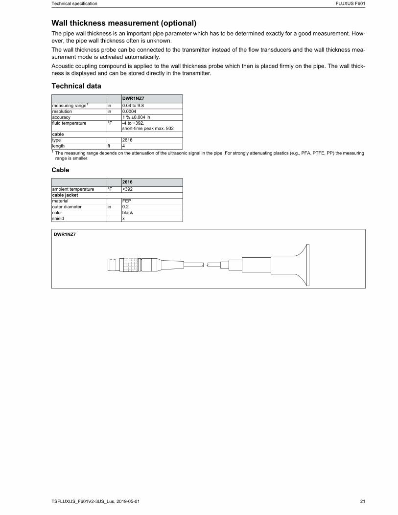
Wall thickness measurement (optional)The pipe wall thickness is an important pipe parameter which has to be determined exactly for a good measurement. How-ever, the pipe wall thickness often is unknown.
The wall thickness probe can be connected to the transmitter instead of the flow transducers and the wall thickness mea-surement mode is activated automatically.
Acoustic coupling compound is applied to the wall thickness probe which then is placed firmly on the pipe. The wall thick-ness is displayed and can be stored directly in the transmitter.
Technical data
Cable
DWR1NZ7
measuring range1 in 0.04 to 9.8resolution in 0.0004accuracy 1 % ±0.004 influid temperature °F -4 to +392,
short-time peak max. 932сabletype 2616length ft 41 The measuring range depends on the attenuation of the ultrasonic signal in the pipe. For strongly attenuating plastics (e.g., PFA, PTFE, PP) the measuring
range is smaller.
2616
ambient temperature °F <392cable jacketmaterial FEPouter diameter in 0.2color blackshield x
DWR1NZ7

2019-05-01, TSFLUXUS_F601V2-3US_Lus
FLEXIM AMERICAS CorporationEdgewood, NY 11717
USA
Tel.:(631) 492-2300Fax:(631) 492-2117
internet: www.flexim.come-mail: [email protected]
1-888-852-7473
Subject to change without notification. Errors excepted.FLUXUS is a registered trademark of FLEXIM GmbH.
Copyright (©) FLEXIM GmbH 2019