ports & maritime - cavoteccavotec.co.uk/pdfs/ports and maritime.pdf · • stacker &...
TRANSCRIPT

Ports & Maritime
Market Unit Brochure

Motorised cable reels are usually divided into applications for horizontal and vertical reeling with a further distinction being made between Intermittent Duty and Continuous Duty applications.
For Intermittent Duty applications, our Hydrodynamic System is usually recommended due to its simplicity and re-liability. Key features of this system include compact design, even torque output in reeling and unreeling mode, standard motor and low maintenance. Normal torque outputs are 10-700 daNm with speeds ranging from 10 to 60 m/min.
For Continuous Duty applications, we recommend our family of T-series gearboxes. These can be used with several drive systems and fitted with different drums such as monospiral, random lay, parallel lay and a Pull & Store configuration.
We recommend our Torque Motor units for small re-els and slow speed applications (5-40 daNm and 0-60 m/min), while our Cavotec Reel Control (CRC) is best suited for larger reels (torque output 40-750 daNm).
Motorised Cable Reels
GUIDELINES FOR CABLE REEL SELECTION
CAvOTEC SpECImAS hAS ESTABLIShED ITSELF AS A LEADING SUppLIER OF INNOvATIvE, ROBUST AND COmpACT SySTEmS, BACkED By ExpERT ENGINEERING CLIENT SUppORT.
AppLICATIONS TEND TO BE DIvIDED INTO ThOSE REqUIRING hORIzONTAL AND vERTICAL mOvEmENT AND BETwEEN INTERmITTENT AND CONTINUOUS USE.
2 Motorised Cable Reels

3
The above chart shows different typical cable reel applications related to the most suitable cable reel system and drive.
1
3
4
2
1. Motor (with drive) Standard squirrel cage motor, according to IEC Norms. Alternatively, the cable reel can be supplied with a pneumatic or hydraulic motor.
2. Gearbox or Torque Unit Seven gearboxes and eight torque units are available with variable output torque from 10-1200 daNm.
3. Collector Standard sizes of collectors are available for power and signals. Current ratings vary from 10 to 2400Amp, voltages up to 30kV. We also manufacture customised collectors exceeding the above parameters.
4. Drum The drums are composed of standard elements and can easily be adjusted to required widths. Standard drum diameters range from 300mm to 8700mm.
CAvOTEC CABLE REEL SySTEm
Typical cable reel applications
ContinuousDuty
IntermittentDuty
10 20 40 80 160 320 640 1280Torque Output (daNm)
Large RMGC’s Log handlers •• Bridge Cranes Small 100% ED• Small Vertical Applications
• Drill Jumbos Harbour
• Stacker & Reclaimers• Vertical Applications
• Ship-to-shore Cranes Pull & Store Applications
• Trippers Small Cranes
Hydrodynamic Torque Motor CRC
• Small RMGC’s Gantry Cranes• Large Vertical Applications

The most unique feature of the Cavotec hydrodynamic system is that the clutch acts directly on the main drum shaft. This gives an even torque output in reeling and unreeling modes, independently of clutch slip or reeling speed, thus assuring long cable life.
Due to its unique design our hydrodynamic system provides a simple and rational solution for many cable and hose reel applications. The system is based on a gearbox in which a reduction gear, clutch and brake are built as one unit. It provides a constant torque output, allowing an even recovery of any type of cable.
Our hydrodynamic cable reel is driven by a standard squirrel cage motor but can also be supplied with a hydraulic or pneumatic motor. Another major advantage is that the torque can easily be readjusted on site. This way, the tension of the cable may be reduced or increased according to the actual requirement.
hyDRODyNAmICSySTEmS
4 Motorised Cable Reels

The chart above shows typical torque/speed for a hydrodynamic torque unit with a completely even torque output. The torque variation due to slip or reeling speed does not exceed 5-10%, depending on the size of the torque unit.
Slip/Torquediagram
Nominal Torque
Drum Speed (rpm)
-30 -20 -10 0 +10 +20 +30
1,0
2,0
5
Torque/speed diagramm for hydrodynamic unit

The Cavotec torque motor for cable reels has been designed to provide a virtually constant torque in reeling and unreeling mode. The system is also designed for continuous duty. The resulting mechanical cable tension could be compared to a hydrodynamic system. This has been obtained by using a torque motor with a very flat torque/slip curve. The motors are used up to maximum of ± 400 rpm and, within this range, the torque fluctuation is approximatley 10%. Besides the motor characteristics, the gearbox
efficiency also influence the traction to which the cable is submitted. The T-series gearboxes are designed with this in mind. They incorporate a single shaft planetary gear which makes them highly reversible. The torque motors are equipped with an electromagnetic brake and are servo-ventilated. The standard protection class is IP55 and the motors are suitable for environment temperatures up to 40°C. Special ventilation and motor insulation are supplied for higher temperature ranges.
1. Self-braking torque motor2. Pre-reducer3. Gearbox4. Collector5. Drum
CAvOTEC TORqUEmOTOR SySTEm
1
2
345
6 Motorised Cable Reels

The Cavotec cable reel with CRC drive is the result of a technical cooperation between drive manufacturers and Cavotec. The CRC system achieves precise speed and torque control of standard maintenance-free squirrel cage motors. A slipping device between motor and gear-box is not needed.
The Cavotec CRC driven cable reel allows an almost constant pull on the cable. In fact, by following the
torque reference signal computed on the basis of reeling variables – such as cable weight, reeled cable on the drum, acceleration or deceleration of the crane, position on the track – the CRC minimises the pulling force on the cable.
Cavotec has also chosen to use oversized, not force ventilated, motors for reliability and for simplicity in system layout. The result is a longer cable life and increased reliability of the cable reel system.
CAvOTEC TORqUE CONTROL (CRC), DRIvE
7
1
2
CavotecSpecimas
3
4
1. CRC drive.2. Standard squirrel cage electric motor.
One or more motors can be used in parallel.
3. Pre-reducer and holding brake.4. Main gear-box.

CAvOTECREEL CONTROL(CRC)
M3 ~
Power supply
Interlocking for crane
SignalCavotecSpecimas
applicationsoftware
PowerOutput
Interlocking for crane
Brakesignal
Chopper Resistor
Encoder
Brake spring app.elect. released
AUX power
220V AC
Drum
Gearbox
Transducer
Torque reference
Processing
Cablereel motor
Brake controlcircuit
Slipringassembly
1. CRC drive.2. Standard squirrel cage electric motor. On or more motors can be used in parallel.3. Pre-reducer and holding brake.4. Main gear-box.
Standstill slipring applications often require a high degree of de-rating of the current capacity of conventional carbon brush gear. Increasing the physical size of the brushes is not always a solution, since the actual contact area does not increase proportionally. Cavotec has overcome this problem by developing a multi-contact brush gear, which has effectively drastically increased the capacity. A division of the brush into independent sections, thus ensuring a larger effective contact area, achieves this.
kp BRUShES
8 Motorised Cable Reels

Optical signals are increasingly used in ports and terminals, where both composite and fibre-optic bundles are common.
To meet these demands, Cavotec has developed a fibre-optic rotary accumulator. Thanks to its innovative design, this unit can also be used as a stand-alone rotary accumulator if the reel is equipped only with fibre-optic cable. The housing is made of stainless steel and includes anti-condensation heating elements and rotary limit switches. The signal transmission is uninterrupted, and with a fibre length of about 15 m in the rotary connector, fibre dimming can be disregarded.
A dimming of less than 3 dB must be taken into account for the rotary accumulator (including any bilateral connections). The connection is made on either side via plug connectors in the fixed and rotating terminal boxes.
Cavotec has developed a range of cable guides designed to ensure smooth cable guiding during crane operation. Engineered to the highest standards, these guides improve the operational life of cables and ensure continuous safe crane operation.
FIBRE OpTICROTARyACCUmULATOR
CABLE GUIDES
9

Panzerbelt guarantees the cable inside the channel is entirely protected from vehicles crossing the track and from objects falling into the cable duct. The system has several major advantages over other, more conventional cable protection systems:
• Complete operational safety• Low installation cost• Full cable protection• Maintenance free• No load restrictions• Channel free from spillage• Operates in any climate• No crane speed limitations• No alignment problems• Easily adaptable to existing systems
The most significant feature of the Panzerbelt System is the belt itself. Defined and perfected after decades of testing and practical experience, it is able to perform apparently conflicting duties: it has a high transversal rigidity necessary to support all vehicle types while simultaneously possessing sufficient longitudinal flexibility to allow the belt to be lifted into a near vertical position.
Thanks to its high quality design and manufacture, the belt resists mechanical, ambient and abrasive wear extremely well, significantly reducing maintenance costs.
mAIN ADvANTAGES
TEChNICALChARACTERISTICS
Panzerbelt
The main components of the Panzerbelt system are: 1. Stainless steel rivets2. Pre-drilled fixing strip3. Panzerbelt steel reinforced rubber cover4. Stainless steel channel profile
10 Panzerbelt
pANzERBELT IS A CABLE pROTECTION SySTEm INCORpORATING A CONTINUOUS SEmI-FLExIBLE BELT, FABRICATED FROm RUBBER wITh INLAID STEEL REINFORCEmENT, whICh LIES OvER A ChANNEL CAST IN ThE qUAy.
ThE BELT IS RIvETED TO ThE qUAy SURFACE ALONG ONE EDGE, whILE ThE OThER REmAINS FREE TO BE RAISED By A CABLE GUIDE AND BELT-LIFTING DEvICE FITTED TO ThE CRANE. STEEL REINFORCEmENT hAS BEEN INCORpORATED TO RETAIN STRENGTh AND FLExIBILITy OF ThE BELT IN ALL DIRECTIONS.

Ambient temperature: -30°C up to 80°C
Opening angle: 90° max
Estimate lifetime: > 250,000 cycles (open/close)
Horizontal bending radius: 35m (minimum) with hinge profile external; 45m (minimum) with hinge profile internal
Maximum load: The maximum load applied on a Panzerbelt System with a 100mm wide slot should not exceed 400 N/cm2
Maximum breaking load at joint: 1750kg for standard Panzerbelt; 2650kg for Super Panzerbelt
Elongation: 2% with load of 3000 N
Approx. lenght of rolls: 50m
Max force to open the belt at 90°: 40kg
11
Weight (kg/m)dimension A (mm)TypePB 300 295 ≈ 6.0PB 400 395 ≈ 7.5PB 500 495 ≈ 9.5PB 600 595 ≈ 11.5
Standard Panzerbelt type PB
*rebbuR eneidatuB enerytS-RBS %08:slairetaM15% Steel cord
5% Nylon
* Other types of rubber and reinforcement layers are available for special working enviroments.
Reinforcing: Warp: • Two layers of RFL dipped nylon yarn - breaking load 50 kN/m
Weft: • Brass coated steel cord - breaking load 640 kN/m
A
15
15 30.5 80.5
A
15
15 30.5 80.5
Weight (kg/m)dimension A (mm)TypeSPB 300 295 ≈ 6.5SPB 400 395 ≈ 8.0SPB 500 495 ≈ 10.0SPB 600 595 ≈ 12.0
Super Panzerbelt type SPB (USA and Europe Patent)
:slairetaM15% Steel cord10% Nylon
Reinforcing: Warp: • Two layers of RFL dipped nylon yarn - breaking load 50 kN/m
• Two layers of RFL dipped nylon fabric - breaking load 55 kN/m
• Two layers of RFL dipped nylon fabric - breaking load 160 kN/m
Weft: • Brass coated steel cord - breaking load 640 kN/m
rebbuR eneidatuB enerytS-RBS %57
GENERAL ChARACTERISTICS OF ThE BELT

SImpLE AND FASTINSTALLATION
12 Panzerbelt
Thanks to its innovative and versatile design, the Panzerbelt System can be installed in any type of port with relative ease and can be fully customised to meet any given operational requirement. Retrofitting is also possible, even without using the stainless steel channel.
A standard Panzerbelt System consists of the following components:
• EitherStandardorSuperreinforcedbeltinrollsofapprox. 50m, with joints at their ends
• StainlesssteelchannelAISI304orAISI316, 1.5mm thick
• Hotdipgalvanised30x8mmfixingstrips,with 13 predrilled holes per metre
• Stainlesssteelornickelcopperrivets• Earthingcopperstripswithscrewsandnuts• Anti-fillingandalignmentsystemwithexpanded
polystyrene• Alignmentbracketsforchannelsections

The Panzerbelt channel is made of stainless steel sheet and serves primarily as a framework for the creation of a duct in the quay. It is shaped to provide a recess for the belt thereby ensuring protection of its edges. It also carries the additional profile allowing the belt to be firmly fixed to the concrete quay.
Belt sections are supplied with galvanised steel joints already fixed at one end. The rivets used to connect the joints to the belt sections are the same as those used to fix the belt to the channel.
Panzerbelt can be supplied with several optional items including:•Stainlesssteelturnoveranchors(singleordouble)•Junctionboxes•FixedPanzerbeltopeningdevices•Beltliftingdevices•Easyliftaccesscovers(springloaded)
Thanks to the characteristics of the flexible rubber cover, the belt-lifting device has a simple and light construction. The device is made of stainless steel with rollers in nylon charged with molybdenum and is easily adaptable to existing cable guides or pick-up systems.
SySTEmACCESSORIES
13
ThE STANDARD ChANNEL

MoorMaster™
Cavotec’sautomatedmooringsystem,MoorMaster™,uses vacuum and hydraulic based technology instead of mooring ropes, simplifying vessel mooring to a press of a button. Mooring is entirely automated and can be performed in as little as 25-30 seconds.
Key advantages of the system include:
Safety •Reducedriskofmooringaccidentsasmanisremoved fromhazardworkingzones. •Real-timemonitoringofactualmooringprocessand forces during the port stay.
Infrastructure • Improvedpierutilisationduetocloservesselspacing. •Quaylengthcanbe‘virtuallyextended’astheship’s bow can overhang the end of the quay. •MoorMaster™mayreducearequirementforextension of breakwater protection.
Efficiency •Highercontainertransferrates. Shipisheldsteady alongside, which may allow for the automation of shore cranes in future.•Shipmotionduetoswell,surge,passingshipsetc is dampened.• Improvedcontinuityofworkprocesses. •Shorteroperatingtimesfortugs. •Nomooringteamsrequired,harbourpilotsable to disembark faster.
Environment •Reducedemissionsasshipsenginescanbeshutdown
earlier and tugs leave earlier.•Quickerconnectiontoshorepowerifavailable.
GENERALINFORmATION
14 MoorMaster™
AUTOmATED mOORING SySTEmS
TRADITIONALLy, mOORING ShIpS hAS ALwAyS BEEN DONE wITh ThE USE OF ROpES. ThIS pRACTICE hAS REmAINED UNChANGED DESpITE STRONG TEChNICAL DEvELOpmENTS wIThIN pORTS AND ShIppING OvER RECENT DECADES.
ThE AUTOmATED mOORING SOLUTIONS DEvELOpED By CAvOTEC mOORmASTER NOw BRING mOORING Up TO SpEED wITh ThE pACE OF ThE mODERN ShIppING INDUSTRy.

Container terminals have become a crucial link in today’s global economy. Often they are the main logistics hub for a large geographical region ensuring the smooth exchange of consumer goods, commodities and industrial products. Gains in efficiency and productivity from improvement of the ship to shore interface is potentially significant further down the logistics chain and can have a profound impact on the commercial success of terminal operators, shipping lines and their customers.
Container ships are becoming larger and in many ports the mooring of these huge vessels with ropes can easily exceed 30 minutes. With MoorMaster™ the vessels are moored in a matter of seconds, allowing shore personnel faster access to the vessel to begin cargo operations. In surge-affected ports, MoorMaster™ holds ships steady providing a stable platform for faster crane and cargo movements.
SOLUTIONSFOR CONTAINERTERmINALS
15

Transport of RoRo cargo by sea plays an increasingly important role in reducing road congestion. Good examples are the specialised pure car carriers (PCTC) which form an integral part of the logistics chain within global car manufacturing, and passenger ferries which are mostly employed on short sea routes where reliability of schedule and quick crossing times are of vital importance.
While many RoRo ships and ferries trade on fixed routes, adaptability to different ports remains important to ship owners and terminal operators. With increasing ship sizes, the challenge is often to safely moor in adverse environmental conditions, especially where pier space for ropes is restricted.
The Cavotec MoorMaster reduces the amount of time vessels need to spend in port and allows terminals to operate in adverse environmental conditions that are incompatible with traditional rope mooring. Retrofitting existing terminals with Cavotec MoorMaster allows usage by vessel sizes beyond the original design envelope, without the need for investment in expensive pier extensions or dolphin contructions that also may disturb restricted waterways in the port.
SOLUTIONSFOR RoRo AND FERRy TERmINALS
16 MoorMaster™

SOLUTIONSFOR DRy BULk AND TANkER TERmINALS
The MoorMaster™ 200LS (Lock System) is designed specifically for use in locks in harbours and inland waterways. The MoorMaster™ cuts vessel transit times and creates a safer environment for those working on ships and shore-side.
Bulk cargoes represent the largest proportion of global trade categories by volume, and transporting by sea remains the most effective option. Bulk carriers are categorised according to their size, and vessels in a given class share similar hull shapes and dimensions.
SOLUTIONS FOR LOCk SySTEm
17

Alternative Maritime Power
Cavotec supplies two types of shore-to-ship power systems. One incorporates a ship-based or shore-mounted cable management system with shore connection made via high voltage cables to a pit fitted into the quay or to ashipsocketoutletJB. Ourshore-sidepitsaredesignedto occupy a minimum amount of space. The ship-based cable management system consists of the following components: electrical connectors (up to 12kV), flexible cables, slipring, optical fibre accumulator, motor reducer, cable drum, electrical control panel and a retractable hydraulic cable guide.
The second alternative is similar to the ship-based version, although fitted inside a standard container and stored on board ship, either aft or forward of the accommodation block. As the system is entirely modular, the container can be moved according to vessel or loading requirements.
Amp – ChALLENGES AND SOLUTIONS
18 Alternative Maritime Power
ThE ENvIRONmENTAL ImpACT OF ThE GLOBAL pORTS INDUSTRy IS INCREASINGLy BECOmING A hIGh-pROFILE ISSUE.
IN ThE pAST 15 yEARS, CONCERTED EFFORTS hAvE BEEN mADE TO REDUCE EmISSIONS FROm ShIpS’ AUxILIARy DIESEL ENGINES whEN IN pORT.

For cruise ships, the power cables are handled on shore. The socket outlet receiving panel is normally installed in a dedicated room on the lower decks which can be accessed from the shore through a water tight hatch. Cavotec has developed a specific range of solutions for these types of applications. AMP Mobile guarantees the highest operational flexibility along the berth: accommodating a wide range of vessel types and shore connection points. When not in use, AMP Mobile can easily be moved from the quayside and parked elsewhere.
Quaysidespaceincontainerterminalsisatapremium,soour shore-to-ship power cable management systems are vessel-based and include two types:•Ship-integratedsystem•Semi-fixedcontainerisedsystem
The ship-integrated system includes all equipment necessary for shore connection, including the cable management system, installed on board, often near crew quarters and in the vicinity of the electrical room. This option tends to be recommended for new-build projects.
SOLUTIONS FORCRUISE ShIpS(6,6kv / 11kv)
SOLUTIONS FOR CONTAINER ShIpS (ShIp INTEGRATEDSOLUTION 6,6kv)
19

Space constraints on vessels can preclude the installation of a fixed module. Seeking to overcome this, Cavotec has developed a shore-to-ship power system housed in either one 40ft container or two 20ft containers. The cable management system and all electrical components
are also installed in the container(s). Operators therefore have the option of moving the containers according to loading and other requirements.
In order to supply power to each individual cable management system, a shore pit must be installed on the quay. This connection pit serves as the main connection point for all the cables leading from the main quay power supply up to the cable management system.
The Cavotec shore pit consists of:
• One-Hand Lift, Load-Rated Cover Assembly (with optional Fiberglass Pit Form and Cable Roller Guide) and concrete embedded frame.
• Stainless steel shore power junction box (IP66).• Electrical sockets up to 12kV (fitted with safety features
such as pilots and interlocks).• Optical fiber connectors.
SOLUTION FORCONTAINER ShIpS(SEmI FIx CONTAINER 6,6kv OR 6,6kv/440v)
ShORE pIT
20 Alternative Maritime Power

Bringing more than 40 years’ experience of high-load rated, one-hand lift covers, Cavotec has designed the ’Easy Lift Cover Assembly’. This robust, cost-effective, marine-grade assembly enables operators to safely open the covers with a lift weight of only approx. 15kg. Furthermore, the Easy Lift covers require a positive force to close so they can not accidentally slam closed on an operator. Cavotec Easy Lift Covers can be produced to meet site-specific size and load-bearing requirements.
We also manufacture a fiberglass pit form for use in conjunction with the Easy Lift Cover. Use of this pre-formed fiberglass enclosure can result in significant on-site labour savings since time-consuming forming of the concrete vault is no longer required, and internal components, such as the stainless steel junction box, can be factory installed prior to shipment.
Since 1988, Cavotec has also engineered numerous state-of-the-art shore-based cable management systems for Ro-Ro vessels and ferries, that tend to use dedicated berths and dock in the same positions.
In these cases, the degree of flexibility required from cable management systems is not as great, allowing the equipment to be integrated into the berth.
Cavotec has also developed similar systems for integration into dolphins specifically for tankers and LNG vessels.
EASy LIFT COvERASSEmBLy
ShORE BASEDSOLUTION
21

Marine Slipring Systems
With more than 80 vessels using the Azipod propulsion with Cavotec sliprings installed, the system has accumulated more than four million hours of operational service, making the Cavotec MPS Slipring System an industry standard.
Cavotec MPS slipring:
• Slipring design range from data and signal voltages to 6kV power phase voltage
• Slipring design range from mA data and signals to 6000Amp power phase currents
• Hydraulic swivel joint design range from low pressure pneumatic or hydraulics to 350 Bar hydraulic pressure
• All in one, complete slip ring with hydraulic joint and auxiliary equipment, supplied in one easily mounted unit
• Simple installation using standard mechanical, electric and pipe interfaces
• Carefully designed bus-bar system with symmetric current flow and multi contact point carbon brush system
• Self-cleaning ring and brush system of self cleaning type• Basic design test at resonance frequencies of up to 2G
and at shock loads of up to 5G• Low maintenance with easy and fast replacement of rings
and brushes if required• Customised design• Client-specific auxiliary equipment available, for example:
steering feedback, control and support equipment
mARINE SLIpRING SySTEmS
22 Marine Propulsion System
CAvOTEC hAS wORkED CLOSELy wITh ENGINEERING GROUp ABB SINCE ThE 1990’S ON DEvELOpING ELECTRIC pOD pROpULSION FOR CRUISE ShIpS, ICE BREAkERS AND OThER ICE CLASS SpECIAL pURpOSE vESSELS.
23
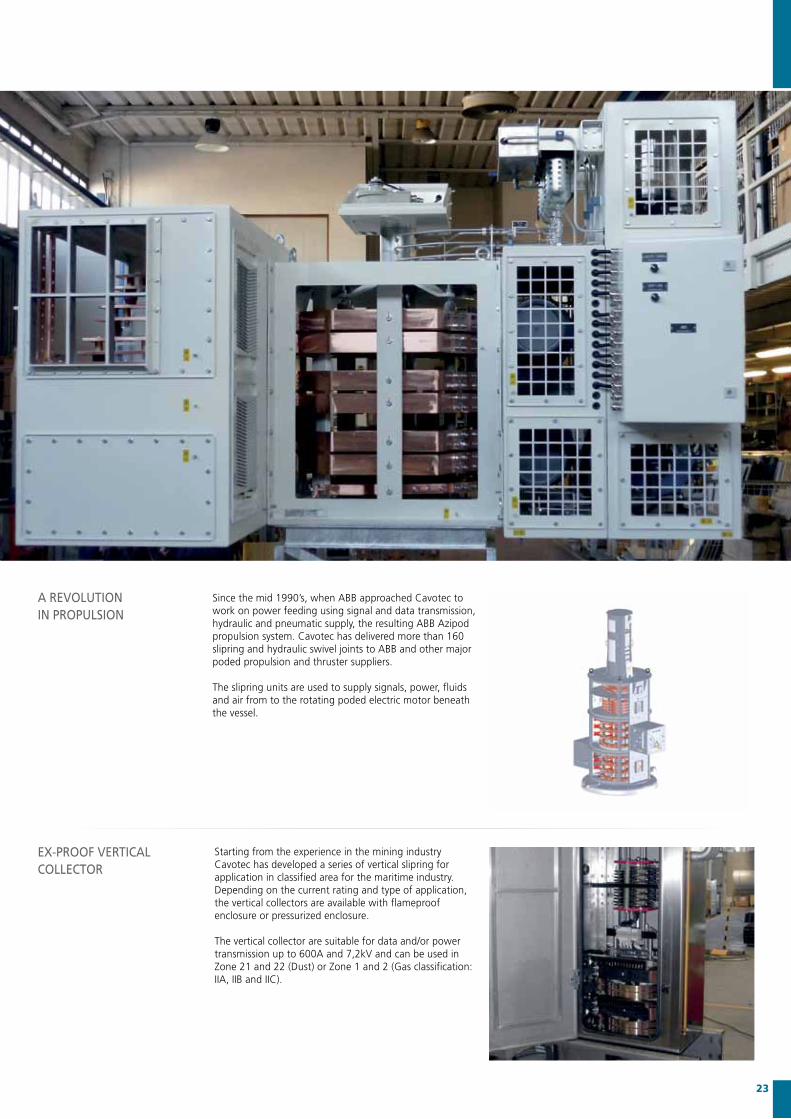
Since the mid 1990’s, when ABB approached Cavotec to work on power feeding using signal and data transmission, hydraulic and pneumatic supply, the resulting ABB Azipod propulsion system. Cavotec has delivered more than 160 slipring and hydraulic swivel joints to ABB and other major poded propulsion and thruster suppliers. The slipring units are used to supply signals, power, fluids and air from to the rotating poded electric motor beneath the vessel.
Starting from the experience in the mining industry Cavotec has developed a series of vertical slipring for application in classified area for the maritime industry.Depending on the current rating and type of application, the vertical collectors are available with flameproof enclosure or pressurized enclosure.
The vertical collector are suitable for data and/or power transmission up to 600A and 7,2kV and can be used in Zone 21 and 22 (Dust) or Zone 1 and 2 (Gas classification: IIA, IIB and IIC).
A REvOLUTIONIN pROpULSION
Ex-pROOF vERTICAL COLLECTOR

24 Marine Propulsion System
The cavotec Marine collectors can be equipped with slipring for data transmission. These sliprings are specifically designed for the transfer of small streams of data. Six gold-coated contact fingers guarantee secure transmission in a wide variety of applications including all standard field bus systems such as CAN bus, ASI-Bus and Profibus. They can also transfer Category 5e and 6 Ethernet signals of up to 1Gbit and audio and video signals.
Modular design enables assembly specific to customer requirements. There are different ring diameters available, ring spacing is determined by specific voltage requirements, and it is possible to incorporate power rings. The integration of encoders and limit switches is also possible.
SLIpRINGS FOR DATA TRANSmISSION

25

Power Connectors
Customers have the option of ordering our power connectors and plug & sockets pre-fitted in standard units, including circuit breakers. Cavotec also produces a comprehensive range of multi-pin outlets for control cables, manufactured for an upper limit of 50 pins and 40Amps. The range of connectors can be divided into two different operating systems: Push & Pull and Screw Ring types.
Cavotec power connectors make use of a special technique using lamellar technology with multi-contacts (Multi-Way Technology).
The lamellar system MWT greatly improves the contact between the male pin and female contact. When the MWT becomes warm it expands thus increasing the contact pressure between the surfaces. This additional contact pressure allows for an exceptional current-carrying capacity relative to the size of the contacts and makes connecting and disconnecting the plug and socket easier.
MWT system contacts
INTRODUCTION
26 Power Connectors
CAvOTEC CONNECTOR’S LOw AND mEDIUm vOLTAGE ELECTRICAL pOwER CONNECTORS ARE DESIGNED TO mEET ThE INTENSE DEmANDS OF ThE pORTS AND mARITImE SECTOR, AND mEET A vAST ARRAy OF INDUSTRy REqUIREmENTS.
ThEIR hIGh qUALITy DESIGN mAkES OUR CONNECTORS INDUSTRy FAvOURITES ThE wORLD OvER.
12mm

All Cavotec connectors are provided with interlocking pilot contacts. The pilots are last to connect and first to disconnect, so that inserted in a proper safety wiring, this insures that no disconnection under load can take place. Mechanical interlocking can be provided on request.
All connectors are manufactured in accordance with NFC 63300 rules and additionally confirm to the following standards NFC 20 040, VDE 0110, NFC 63300 IEC 309-1, CEE 17, BS 4343 IEC 529, DIN 40050, NFC 20010. The Cavotec high voltage Push & Pull connectors are tested according to VDE 0432 - List 2.
All Cavotec power connectors have a standard inter-protection class of IP667, while our range of power units have a standard inter-protection class of IP557.
NORmS ANDREGULATIONS
Type size N° Pins Max current AMP Max voltage kV Screw Ring/Push&Pull
PC4 4/5 250 1,1 YES / YES
PC5 4/5 420 1,1 YES / YES
PC6 4 660 1,1 NO / YES
PC5_K 4 350 7,2 YES / YES
PC6_K 4 540 7,2 NO / YES
PC6_L 4 500 12 NO / YES
PC8 4 500 25 YES / NO
27

Cavotec power connectors for low voltage applications are robustly designed for use in harsh and demanding environments. They have a standard inter-protection class of IP667 and have a standard maximum temperature resistance of 80°C. On request, the maximum temperature range can be extended to a maximum of 400°C.
Their robust versatility makes our power connectors ideal for offshore, railway, port, bulk and container handling applications.
Our electrical connectors provide a flexible, convenient and reliable means of extending cables from fixed or mobile powers sources to ships, cranes and other cargo handling equipment. They are also often used for portable junction boxes either in above- or underground applications.
LOw vOLTAGEpOwER CONNECTORS Up TO 1100v
mEDIUm vOLTAGE pOwER CONNECTORS Up TO 25000v
28 Power Connectors

Cavotec Connectors has also developed a standard range of power units made in 2mm stainless steel plate designed for the same harsh environments as the plugs and sockets. The cabinets are custom made to fit any requirements.
Cavotec has designed standard outlet panels for 150A to 630A with a voltage range of 380V to 1000V. These are equipped with molded-case circuit breakers interlocked via the pilot contacts in plug and socket. On request, Cavotec also provides power units in 2mm AISI 316 stainless steel.
The Cavotec PC2-EX is an Ex-rated connector designed for use in the oil and gas industry and for petrochemical applications. Used on offshore and land-based oil rigs to power top drives, and magnets and motors as well as low current applications like lights and signalings. Other applications include pits in aircraft maintenance hangars and petrochemical processes.
Made from marine grade aluminium, the unit is uniquely light and compact and can be fitted with a wide range of insulator assemblies covering any cable size from 1,5mm2 up to 300mm2. Maximum voltage is 690V, and currents of up to 660A are possible. The body can be anodised and painted to protect against the extreme environments found on offshore oil rigs.
pOwER UNITS
ExpLOSION pROOFpOwER CONNECTOR
29

FLT - Spring Driven Cable Reels
Spring driven cable reels are subject to the standards set out in VDE 0100 and the most recent edition of UVV in Europe countries. Our warranty follows the general delivery conditions of the electric industry for products and services. Cavotec’s spring driven electric cable reels meet all applicable IEC international norms and standards and comply with the latest EU requirements (CE marking).Our cable range includes a wide variety of flexible cables for reeling applications that withstand the highest mechanical stresses and harshest ambient conditions.
Standard inter-protection for drums and slipring bodies is IP66, with the drums being hot-dip galvanised and the slip ring assemblies housing made from glass fibre reinforced polyamide.
OvERvIEw
The drum shall be installed in such a way to ensure that the cable is reeled and unreeled to and from the drum freely. Forced guidance and too small bending radii on sheaves and roller guides should be avoided. The design of the reel allows the feeding point of the cable to be placed on either side of the drum.
In order to make the correct reel selection, it is necessary to know the nature of the application. It is important to take in consideration the heating of the cable due to the number of layers on the drum. Lower temperatures may require a higher spring force due to the higher rigidity of the cable.
Operating conditions
Particular care should be taken regarding operating conditions, especially in extreme environments. The following factors are of primary importance:
• extreme temperatures• substantial temperature variation• humidity levels• vibration• emission
INSTALLATIONINSTRUCTIONS
30 FLT - Spring Driven Cable Reels
CAvOTEC SpRING REELS, mANUFACTURED By CAvOTEC RmS IN FRANCE AND CAvOTEC ALFO IN GERmANy, ARE USED IN pORTS ALL OvER ThE wORLD FOR A wIDE RANGE OF AppLICATIONS.
DESIGNED AND mANUFACTURED TO wIThSTAND ThE ExACTING DEmANDS OF ThIS SECTOR, OUR ELECTRIC CABLE REELS ARE INDUSTRy STANDARDS ACROSS ThE GLOBAL pORTS INDUSTRy.

When selecting the cable, please take in consideration the cable data and the instructions provided by the manufacturer. In order to make the correct reel selection it is absolutely necessary to know the correct conditions of use. It is important to take in consideration the heating of the cable due to the number of layers on the drum. Also when selecting the cable it is important not to exceed the maximum allowed tension of the cable.
The ambient temperature is assumed to be within +30°C to -10°C. Lower temperatures may require a higher spring force due to the higher rigidity of the cable.
CABLE SELECTION
It is absolutely necessary to reel the cable onto the drum without twists or bends. To this end, lay out the complete cable straight along the travel length. When reeling the cable on the drum be sure to maintain the same reeling direction used on the wooden drum delivered by the manufacture.
When roller guides and sheaves are used, it is important to avoid reverse bending whenever possible.
REELING CABLE ON DRUm
31
Wrong
Correct

CAvOTEC mEyERINCk LOADING ARmS ARE USED whEREvER LIqUID pRODUCTS hAvE TO BE TRANSFERRED.
NO mATTER IF IT wILL BE A ShIp, TANk TRUCk, RAILCAR OR ANy kIND OF CONTAINER OUR LOADING ARmS ARE pROvIDING hIGhEST SAFETy COmBINED wITh EASy OpERATION FOR LOADING OR UNLOADING pROCESS. hANDLED LIqUIDS CAN BE ChEmICAL, pETROChEmICAL OR FOOD.
Loading Technology
LOADING ARmS Quality standard Swivel Joints 3” - 32”Sturdy, maintenance free and longlife Cavotec Meyerinck SwivelJointsareusedwhereverrigidpipeshavetofollow3dimensional movements. 2, 3 or 4 bearings combined with two active seals provide highest safety and easy operation.
For instance, more than 3.000 Loading Arms with about 25. 000SwivelJointsareinoperationsince1980.
Loading Arms sizes 3” to 8”Pressure class: 125 PSI / 10 bar to 300 PSI / 25 barMaterial for piping: our standard is stainless steel, carbon steel or aluminum, others on request.Material Swivel Joint: our standard is stainless steel or with internal coating acc. to customers specification on request.Sealings: NBR, FKM, PTFE and others.Temperature: -50°C ÷ +220°C
32 Loading Technology

Filter / WaterSeparators
Filter / WaterSeparators
PumpControlSystem
PumpsPumps
Receiving Filter Station
Ship Receiving StationShip Unloading Station
Rail Car Receiving Station
Tank Truck Receiving Station
Pump and Filter Station
Suction Arms
Tanks
Filter / WaterSeparators
Filter / WaterSeparators
PumpControlSystem
Pumps Pumps
Receiving Filter Station
Ship Receiving Station Ship Unloading Station
Rail Car Receiving Station
Tank Truck Receiving Station
Pump and Filter Station
Suction Arms
Tanks
Loading Technology
Cavotec Meyerinck Marine Loading Arms for river barges are fully counter weight balanced.
Moreover, the loading arms have a self supporting design and are also manually operated due to the high quality of the swivel joints.
The stainless steel Marine Loading Arms can be manufactured with a maximum diameter of 8”. The loading arms can be equipped with special couplers for a quick connection to the ship.
mARINE LOADING ARmS
IN-TANk FLOATING SUCTION UNITS
33
Cavotec Meyerinck Floating Suction Units are used within storage tanks for liquid products.
Float operated they draw of clean product near from the product surface.
Our Floating Suction Units are available for horizontal and vertical tanks but also for floating roofs. They are also available as a single or a double suction arm.
The Floating Suction Units are made of stainless steel and are available from 3” to 32”.
Other materials available on request.
Filter / WaterSeparators
Filter / WaterSeparators
PumpControlSystem
Pumps Pumps
Receiving Filter Station
Ship Receiving Station Ship Unloading Station
Rail Car Receiving Station
Tank Truck Receiving Station
Pump and Filter Station
Suction Arms
Tanks
Filter / WaterSeparators
Filter / WaterSeparators
PumpControlSystem
Pumps Pumps
Receiving Filter Station
Ship Receiving Station Ship Unloading Station
Rail Car Receiving Station
Tank Truck Receiving Station
Pump and Filter Station
Suction Arms
Tanks
Port Fuelling Solutions
Filter / WaterSeparators
Filter / WaterSeparators
PumpControlSystem
Pumps Pumps
Receiving Filter Station
Ship Receiving Station Ship Unloading Station
Rail Car Receiving Station
Tank Truck Receiving Station
Pump and Filter Station
Suction Arms
Tanks
Filter / WaterSeparators
Filter / WaterSeparators
PumpControlSystem
Pumps Pumps
Receiving Filter Station
Ship Receiving Station Ship Unloading Station
Rail Car Receiving Station
Tank Truck Receiving Station
Pump and Filter Station
Suction Arms
Tanks

Radio Remote Controls
Safety, reliability and innovation have been our three guiding principles throughout Cavotec Micro-control’s 20 years’ experience in the industry. Our systems serve a vast array of applications in a broad range of industries, including the offshore oil industry – an indication of our units matching the world’s most stringent safety requirements.
Directives and StandardsAll our RRC units are developed, manufactured, tested and certified in accordance with relevant international directives and standards. Our radio controls conform with EU R&TTE directive EN 300 220 and EMC/ERM standards for short range devices and all our systems’ emergency stop functions are manufactured according to EN-954-1, Cat 2, 3 and 4.
Cavotec Micro-control is a certified manufacturer of Ex-proof equipment and systems according to (ATEX) Directive 94/9/EC.
GENERALINFORmATION
34 Radio Remote Controls
CAvOTEC mICRO-CONTROL’S RADIO REmOTE CONTROL (RRC) SySTEmS ARE BUILT FOR ThE TOUGhEST OpERATING ENvIRONmENTS IN ThE pORTS AND mARITImE SECTOR. wITh BOTh ATEx AND IEC CERTIFICATIONS, OUR RRCS GUARANTEE SAFE AND SECURE COmmUNICATIONS AT ALL TImES, IN ALL CONDITIONS.

Base unit
4. Two way radio link with unique ID-coding, CRC check and hamming distance of 6m.
5. High priority emergency stop message ensures immediate stop.
6. Continuous radio link monitoring. Activation of emergency stop if communication is lost.
Radio terminal and base unit
1. Full system check at power-up.2. Emergency stop ensures immediate stop
of all operations. Redundant monitoring of emergency stop.
3. Redundant monitoring of joystick activity.
7. Dual processor system with surveillance of all safety functions.
8. Radio signal filtering that blocks out all other radio emitters (W-Lan, Bluetooth, GSM).
9. Double monitoring of emergency stop relays.
12
3
4
5
6
710
8
9
35
10. Dual processor system implemented according to IEC61508 ensuring independent processor operation.
Radio terminal
36 Radio Remote Controls
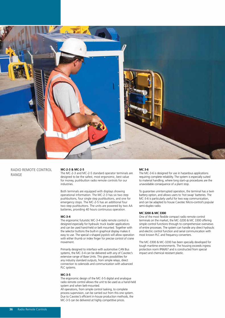
MC-2-3 & MC-2-5The MC-2-3 and MC-2-5 standard operator terminals are designed to be the safest, most ergonomic, best value for money, pushbutton radio remote controls for our industries.
Both terminals are equipped with displays showing operational information. The MC-2-3 has six two step pushbuttons, four single step pushbuttons, and one for emergency stops. The MC-2-5 has an additional four two step pushbuttons. The units are powered by two AA batteries, providing 40 hours continuous operation.
MC-3-4The ergonomic futuristic MC-3-4 radio remote control is designed especially for hydraulic truck loader applications and can be used hand-held or belt mounted. Together with the selector buttons the built-in graphical display makes it easy to use. The special v-shaped joystick will allow operation with either thumb or index finger for precise control of crane movement.
Primarily designed to interface with automotive CAN Bus systems, the MC-3-4 can be delivered with any of Cavotec’s extensive range of Base Units. This gives possibilities for any industry standard outputs, from simple relays, direct connection to solenoids and communication with advanced PLC systems.
MC-3-5The ergonomic design of the MC-3-5 digital and analogue radio remote control allows the unit to be used as a hand-held system and when belt-mounted.All operations, from simple control tasking, to complete process supervision, can be carried out from this one system. Due to Cavotec’s efficient in-house production methods, the MC-3-5 can be delivered at highly competitive prices.
MC 3-6The MC-3-6 is designed for use in hazardous applications requiring complete reliability. The system is especially suited to material handling, where long start-up procedures are the unavoidable consequence of a plant stop.
To guarantee uninterrupted operation, the terminal has a twin batteryoption,andallowsusersto‘hotswap’batteries. TheMC-3-6 is particularly useful for two way communication, and can be adapted to house Cavotec Micro-control’s popular semi-duplex radio.
MC 3200 & MC 3300One of the most flexible compact radio remote control terminals on the market, the MC-3200 & MC 3300 offering simple control functions through to comprehensive overviews of entire processes. The system can handle any direct hydraulic and electric control function and serial communication with most known PLC and frequency converters.
The MC-3300 & MC-3200 has been specially developed for tough maritime environments. The housing exceeds ingress protection norm IP66/67 and is constructed from special impact and chemical resistant plastic.
RADIO REmOTE CONTROL RANGE

37
RADIO REmOTE CONTROLS Ex-proof The MC-3000 Ex and MC-3-6 Ex radio remote controls provide secure and flexible control for a vast range of machinery. In addition to including similar features common to standard radio remote controls (RRCs), these units can also be adapted to use cable control. These systems provide users with an extra guarantee against shutdown if other communication links fail.
Both systems can be delivered with simplex or duplex communication. The duplex communication option allows operators to receive messages, such as alarms and status indications, via LEDs, control display and indicator instruments.
Typical applications for these radio remote controls are offshore oil and gas equipment, mining applications and maritime cranes and winches.

Cable Chains
Our nylon cable chains create substantial efficiency gains by speeding the movement of equipment, while fully protecting the cables and hoses inside. Cavotec cable chains permit any cable combination and are easy to maintain.
Extensive endurance tests carried out by leading crane manufacturers and certification institutes have proven the reliability of the system even in the most extreme working conditions. Our cable chains offer users the following advantages:
• Hydraulic hoses and electric cables• Uninterrupted operation in harsh environments• High speed and acceleration• Reduced maintenance costs and installation time• Turnkey systems equipped with pre-inserted cables
and hoses
OvERvIEw
38 Cable Chains
ESTABLIShED IN 1976, ITALy’S BREvETTI STENDALTO wAS ThE FIRST EvER COmpANy TO pRODUCE NyLON CABLE ChAINS.
ThE INTRODUCTION OF ThIS REvOLUTIONARy ADvANCE IN CABLE AND hOSE pROTECTION hAS mADE BREvETTI ONE OF ThE LEADING SUppLIER OF NyLON AND STEEL CABLE ChAINS IN EUROpE.

Specific applications, characterised by particularly aggressive working conditions, require steel cable chains. Brevetti offers a comprehensive range of steel cable chains designed to meet the increasingly sophisticated demands of industry. Our steel chains are found in all types of applications throughout the world.
The internal and external links used in Brevetti steel chains are made of mild steel that is bright zinc plated.These are separated by anti-friction spacers or with bronze spacers for high temperature applications. If required, steel components can be made from stainless steel AISI 316.
Internal cross elements are either two aluminium blocks, pre-cut with apertures for cables and hoses, or special rods with moveable separators. Special disc springs are installed to compensate for any play between pivot points.
For special applications with long travel distances, Brevetti has developed its own system based on a travelling internal support frame.
STEEL ChAINS
39

Crane Controllers
The large range of different controllers designed and manufactured by Gessman solve the majority of interface issues between operators and machines. Once the physical size and features are determined for an application, the ergonomic issues become a very important part of designing the controller for a specific machine.
In addition to the high quality mechanical systems, a number of electronic solutions have been developed and manufactured by Gessmann, such as Opto-electronic encoders and bus systems.
The Gessmann reference list includes companies such as Siemens, Alstom, General Electric, MAN,Liebherr, Noell, Terex, Konecrans, Potain, Hydralift, Mannesmann-Dematic, Mannesmann-Rexroth, Linde, Kranbau Eberswalde, Steinbock, Boss, Clark, Kalmar, and Kamewa.
Gessmann products are marketed by Cavotec in the following countries: Argentina, Australia, China, Hong Kong, New Zealand, Norway, the UAE, the UK and the US.
GENERALINFORmATION
40 Crane Controllers
GESSmANN INDUSTRIAL CONTROLLERS AND SwITChES, mARkETED By CAvOTEC, ARE USED IN A wIDE RANGE OF AppLICATIONS, INCLUDING CRANE OpERATING SySTEmS, REmOTE CONTROLS AND wELDING mAChINE CONTROLS.
OUR RANGE OF INDUSTRIAL CONTROLLERS ALSO COmpRISES CRANE TEChNOLOGy AND CRANE CONTROLLERS FOR SpECIALISED mARITImE AppLICATIONS, AND FOR SITES wITh A hIGh ExpLOSION RISk.

41

The correct choice of cable is vital to maximise performance and service life. Other critical considerations include:• Minimum bending radius• Tensile stress• Operating speed and acceleration• Installation height and length• Ambient temperature
Flexible Cables
pRODUCT OvERvIEw
1
42 Flexible Cables
CABLES pAy A kEy ROLE IN ThE pORTS AND mARITImE SECTOR. CAvOTEC SUppLIES A wIDE RANGE OF CABLES RANGING FROm STANDARD pOwER CABLES TO hIGhLy ADvANCED pOwER AND SIGNAL CABLES. DEpENDING ON CUSTOmER REqUIREmENTS, OUR CABLES CAN ALSO BE SUppLIED wITh FIBER OpTIC CONNECTORS AND kEvLAR.

Bending radius and overall diameters Precise calculation of the bending radius is a determining factor for cable reliability. A decrease in minimum bending radius has a major effect on the life of a cable because it causes stretching and internal distortions. Another important factor is the frequency of the cable movements. If movement is slow and infrequent a tighter bending radius can be considered. Special attention should also be paid to installations where flexing and torsion is present due to the reels being parallel to the line of travel of the machine.
Tensile strengthThe maximum admissible continuous operating load is calculated by taking the sum of the cross sections of the power conductors (phases + earth of equal cross section) in the cable. Greater loads will result in permanent elongation of the conductors, which would shorten the life of the cable considerably. For occasional or very infrequent stresses the calculated limit can be exceeded slightly. For control cables, where the resistant cross section consists of numerous small conductors, special types of cables are available. In special cases, where the pulling strength exceeds the resistance of the conductors, cables are used fitted with strainers or other means such as Kevlar reinforcement.
Operating speedAll cables in this catalogue have been designed, manufactured and tested for the operating speeds commonly in use today. Of course these speeds are only possible if the recommendations made concerning the choice of cable have been observed. Please note that high acceleration in combination with high operating speeds should be taken into account when calculating the tensile stress in the cable.
Monospiral reelsWhen using this type of reel the natural tendency of the cable is utilised. It is also possible to position the reel in order to eliminate the use of intermediate pulleys and any changes of direction. This increases the life of the cable and the operating speeds considerably.
Multi-spiral and multi-layer reelsThese types of reels are normally used in cases of long cable length and large diameter cables. The current capacity must also be carefully calculated using correction factors for layers and winding.
Spreader cablesSome cables have specially designed to be collected in baskets. With these types of applications a correct design is not only important for good cable treatment but also to avoid operating malfunctions. High stress applications will typically involve long vertical lengths, high speeds combined with lateral movement and a presence of strong winds (typical port conditions). In these cases attention should be paid to ensure that the coiling diameter is no less than 1.5 mtr. and that a guide cone is located in the basket for even coiling of the cable. The shape of the basket and the size and shape of the opening are also important factors.
Other systems of cable movementThe systems most frequently employed are perhaps cable tender systems, pulley systems and cable chains. The first two systems involve high tensile stress whereas the third on a whole does not. Particular attention must be paid to the minimum bending radius and to the distribution of loads between the cables and cable tenders.
CABLE SELECTION
43

Guide pulley and anchoring devicesWhen designing these components, care must be taken to observe the recommended minimum bending radius and also the following factors:
Intermediate sheavesUsedforlongcablelengthsmustbedesignedwitha‘flatbottom profile’ in order to avoid torsion. Small, light-weight rollers are preferred to sheave pulleys or wheels. With twin directional cable guides it is preferable to use light-weight, low friction rollers with a rounded bottom profile, as these types of rollers guide the cable in the centre without developing torsion stresses.
If possible, reduce the number intermediate pulleys and keep changes of direction to a minimum. Where possible rollers instead of pulleys should be used as these have considerably less contact area with the cable. Should the route of the cable require more than one change of direction, the distance between two sheaves or rollers must be greater than 25 times the overall diameter of the cable.
Cable anchoringThe anchoring systems must be designed to distribute the tensile stress over a wide area of the outer cable sheath. This prevents localised faults or damage. It is preferable to make the connections at both ends of the installation by using the same method normally adopted for installations with a central feeding point. Both the reel and the feeding pointmusthaveafew‘dead’turnsofcablebeforethecable joint.
Mobile anchoring points usually consist of ordinary terminalsor‘cablegrips’. Inthesecasesitisrecommendedthat the tensile load is distributed over a length of cable equal to 20-25 times the overall diameter of the cable. It is also recommendable that an additional loop of cable be left before entry into the terminal box to allow movement.
Current carrying capacityCurrent carrying capacities for non-continuous operation in some cases electrical operation is not continuous. In these cases it is therefore advisable to check the values of the operating times so as to determine if the cross section of the cable can be reduced. A typical example of intermittent operating with hoisting equipment consists of repeated cycles where, for example, an operating period of 10 minutes of full load is followed by a longer period without load.
These 10 minutes, taken as a percentage of the total duration (DT) of the cycle, provide the load factor. Load factor ED% = (10/DT min) x 100. In this case the current carrying capacity (as calculated in the preceding paragraph) can be increased using the factors given on page 45. For further information and advice please consult our technical department.
CABLE SELECTION
44 Flexible Cables

4
5
7
9
12
22
29
44
55
66
77
89
101
119
5
6
8
11
14
20
27
35
44
55
81
95
109
124
6
8
10
14
18
25
34
45
55
85
102
120
137
157
184
211
8
10
13
17
22
31
42
55
85
105
148
170
194
227
9
11
15
20
49
79
99
123
147
172
198
275
304
11
14
18
25
32
45
80
99
123
153
184
215
281
329
378
1 LAYER
A0,8
2 LAYERS
A0,61
3 LAYERS*
A0,49
4 LAYERS
A0,42
5 LAYERS
A0,34
6 LAYERS
A0,27
7 LAYERS
A0,22
14
18
24
33
42
59
79
105
130
200
241
282
323
432
19
24
32
43
78
104
138
170
212
370
424
484
1
1,5
2,5
4
6
10
16
25
35
50
70
95
120
150
240
300
18
23
30
41
53
74
99
131
202
250
301
352
404
540
620
23
31
38
47
58
70
82
94
107
145
28
38
58
72
100
132
155
178
47
58
73
90
108
195
224
44
58
72
90
111
134
180
205
241
277
51
84
105
130
182
210
239
281
323
85
105
131
195
298
350
403
84
111
138
172
212
255
297
342
390
459
528
16
25
35
50
70
120
150
240
300
105
139
172
215
319
371
428
488
574
REELED INCROSS-SECTION
mm2
STRECHTED LAYING
AFactor 1
SUSPENDED FREELY IN AIR
A1.05
CABLES UP TO 10 kV
CABLES ABOVE 10 kV
162
461
263
185
56
316
567
651
162
369
496
60
246
226
64
36
26
260
126
68
69
167
146
68
136
36
16
95
185
265
660
110
146
181
226
335
390
449
512
603
278
693
64
162
226
261
68
156
156
36
126
146
166
46
86
116
126
CURRENT CARRyING CApACITy
45

DE-RATING FACTORS FOR vARyING AmBIENT TEmpERATURES
Reel type sleer laripsonoMsleer larips-itluMsuoiraVsuoiraV4321leer no sreyal fo rebmuN
5,08,016,008,0rotcaf noitcerroCselbac talFselbac dnuoRselbac dnuoRelbac fo epyT
For multi-core cables044291410175dedaol srotcudnoc fo rebmuN53,004,054,005,055,056,057,0rotcaf noitcerroC
Cross section of cable mm2 1,5 2,5 4 6 10 16 25 35 50 70 95 120 150 185 240 300srotcaf noitcerroC daoLnoitarud elcyC
Load min. Total DT min. factor-ED%10 17 60% 1,00 1,00 1,00 1,00 1,03 1,07 1,10 1,13 1,16 1,18 1,20 1,21 1,22 1,23 1,24 1,2510 25 40% 1,00 1,00 1,03 1,04 1,09 1,16 1,23 1,28 1,34 1,38 1,42 1,44 1,46 1,48 1,49 1,5010 40 25% 1,00 1,02 1,05 1,13 1,21 1,34 1,45 1,53 1,62 1,69 1,74 1,78 1,81 1,82 1,85 1,8710 50 20% 1,00 1,04 1,11 1,18 1,31 1,45 1,59 1,69 1,79 1,87 1,93 1,97 2,01 2,04 2,10 2,1510 67 15% 1,00 1,08 1,19 1,27 1,44 1,62 1,79 1,90 2,03 2,13 2,21 2,26 2,30 2,32 2,36 2,39
0,49 0,42Reel type sleer laripsonoMsleer larips-itluM
suoiraVsuoiraV4321leer no sreyal fo rebmuN5,08,016,008,0rotcaf noitcerroC
selbac talFselbac dnuoRselbac dnuoRelbac fo epyTFor multi-core cables
044291410175dedaol srotcudnoc fo rebmuN53,004,054,005,055,056,057,0rotcaf noitcerroC
Cross section of cable mm2 1,5 2,5 4 6 10 16 25 35 50 70 95 120 150 185 240 300srotcaf noitcerroC daoLnoitarud elcyC
Load min. Total DT min. factor-ED%10 17 60% 1,00 1,00 1,00 1,00 1,03 1,07 1,10 1,13 1,16 1,18 1,20 1,21 1,22 1,23 1,24 1,2510 25 40% 1,00 1,00 1,03 1,04 1,09 1,16 1,23 1,28 1,34 1,38 1,42 1,44 1,46 1,48 1,49 1,5010 40 25% 1,00 1,02 1,05 1,13 1,21 1,34 1,45 1,53 1,62 1,69 1,74 1,78 1,81 1,82 1,85 1,8710 50 20% 1,00 1,04 1,11 1,18 1,31 1,45 1,59 1,69 1,79 1,87 1,93 1,97 2,01 2,04 2,10 2,1510 67 15% 1,00 1,08 1,19 1,27 1,44 1,62 1,79 1,90 2,03 2,13 2,21 2,26 2,30 2,32 2,36 2,39
0,49 0,42
CURRENT CARRyING CApACITIES CORRECTION FACTORS
CORRECTION FACTOR FOR INTERmITTENT OpERATION
46 Flexible Cables
Ambient temperature °C 10 15 20 25 30 35 40 45 50 55 60 65 70
De-rating Factor 1.18 1.14 1.10 1.05 1.00 0.95 0.98 0.84 0.77 0.71 0.63 0.55 0.45

47
FLExIBLE pOwER AND CONTROL CABLES To be able to offer a comprehensive selection of high quality cables to our customers, the Cavotec Group decided to select specialised manufacturing partners sharing our philosophy on quality and customer service.
In the flexible cables segment, our partners include Baude, Gore, Prysmian, Tratos and Nexans.
We manufacture and service control cables, power cables, fiber optic cables and Kevlar reinforced cables for high stress applications.

vOLTAGE DROp The value is calculated by multiplying the factors K (mV/Am) given on page 49, with the current capacity I (A) of the cable and by the length of the connection L (km). This calculation is valid with sufficient approximation for all voltages where: conductor temperature = 80°C; cos ϕ = 0,8; frequency = 50 Hz. Voltage drop (V) = I(A) x L (km) x K(mV/Am).
The above factors have been calculated using the formula: K(mV/Am) = 1,73 x (R cos ϕ + X sen ϕ) where:R= Resistance of the conductor (Ohm/km) at 50 Hz. X = cable reactance (Ohm/km) at 50Hz.
Values for electrical resistance R (80°C) and for reactance X (calculated for round cables, three phase cores plus earth, but it can also be applied to flat cables) are also given on page 50. Please note that for the conductor temperatures of 90°C, the resistance R must be multiplied by 1,03, while for a frequency of 60Hz, the cable reactance X must be multiplied by 1,2 and the value for K (mV/Am) recalculated.
48 Flexible Cables

49
Nominal crosssection of cable
≤ 1 kV 3 kV 6 kV 10 kV 15 kV 20 kV (cosϕ = 0,8)
Ω / km Ω / km Ω / km Ω / km Ω / km Ω / km Ω / km mV / Am1,52,54
10
16
25
6
35
5070
120150185
240
95
0,1070,1010,0970,091
0,087
0,083
0,082
0,079
0,0780,0760,075
0,0740,0740,073
0,072
0,13
0,1230,113
0,127
0,121
0,1140,1080,104
0,121
0,114
0,108
0,1030,0980,094
0,0910,089
0,109
0,104
0,099
0,0940,0900,088
0,0850,0830,081
0,098
0,096
0,091
0,087
0,0830,0800,079
0,0770,0760,074
0,074
16,9510,156,294,20
2,41
1,54
0,986
0,700
0,4900,3450,260
0,2050,1630,134
0,101
kA (Indicative value) kA
10 kV
50556063
6875788084
15 kV
55606570
7580
20 kV
7580
83
6 kV
45505358
6370727580
3 kV
40434850
5560656872
≤ 1 kV
30354045
5055606570
80
0,20,320,510,771,292,063,224,506,43
9,0012,215,419,323,8
31,0
1,52,5461016253550
7095120150185
240
Operating electricalresistance (R)
at 80°C, A.C. 50 Hz
Nominal crosssection of cable
1 secondTHERMAL LIMITfor all voltage
Reactance (x) at 50 Hz for three core+earth cablesat operating voltage of:
Voltage drop
mm2
factor k
11,06
0,770,57
3,45
2,24
1,46
0,36
0,22
14,223,5
8,805,93
0,45
0,300,26
DYNAMIC LIMIT for three core cable operating voltage of:
(mm2)
FACTORS FOR CALCULATION OF vOLTAGE DROp

50 Flexible Cables
Nominal crosssection of cable
≤ 1 kV 3 kV 6 kV 10 kV 15 kV 20 kV (cosϕ = 0,8)
Ω / km Ω / km Ω / km Ω / km Ω / km Ω / km Ω / km mV / Am1,52,54
10
16
25
6
35
5070
120150185
240
95
0,1070,1010,0970,091
0,087
0,083
0,082
0,079
0,0780,0760,075
0,0740,0740,073
0,072
0,13
0,1230,113
0,127
0,121
0,1140,1080,104
0,121
0,114
0,108
0,1030,0980,094
0,0910,089
0,109
0,104
0,099
0,0940,0900,088
0,0850,0830,081
0,098
0,096
0,091
0,087
0,0830,0800,079
0,0770,0760,074
0,074
16,9510,156,294,20
2,41
1,54
0,986
0,700
0,4900,3450,260
0,2050,1630,134
0,101
kA (Indicative value) kA
10 kV
50556063
6875788084
15 kV
55606570
7580
20 kV
7580
83
6 kV
45505358
6370727580
3 kV
40434850
5560656872
≤ 1 kV
30354045
5055606570
80
0,20,320,510,771,292,063,224,506,43
9,0012,215,419,323,8
31,0
1,52,5461016253550
7095120150185
240
Operating electricalresistance (R)
at 80°C, A.C. 50 Hz
Nominal crosssection of cable
1 secondTHERMAL LIMITfor all voltage
Reactance (x) at 50 Hz for three core+earth cablesat operating voltage of:
Voltage drop
mm2
factor k
11,06
0,770,57
3,45
2,24
1,46
0,36
0,22
14,223,5
8,805,93
0,45
0,300,26
DYNAMIC LIMIT for three core cable operating voltage of:
(mm2)
0,103
0,0950,092
0,083
0,078
0,078
0,075
0,075
0,073
0,072
0,071
0,071
0,071
0,070
10,1
4,19
2,41
1,53
0,983
0,343
0,204
0,104
1,5
2,54
6
10
25
35
50
70
95
120
150
185
240
NOMINAL CROSS SECTION
mm2
≤ 0,6/1 kV(X)
Ohm/km
0,108
0,102
0,097
0,092
0,088
0,085
0,083
0,081
0,080
3,6/6 kV(X)
Ohm/km
A.C. RESISTANCEAT %= Hz and 80 °C
(R)Ohm/km
REACTANCE AT 50 Hz FOR THERE CORE CABLE (3 PHASE + EARTH) AT OPERATING VOLTAGE:
0,111
0,105
0,100
0,095
0,091
0,087
0,085
0,083
0,082
6/10(X)
Ohm/km
0,118
0,111
0,105
0,100
0,095
0,092
0,089
0,087
0,084
8,7/15(X)
Ohm/km
0,118
0,112
0,106
0,101
0,097
0,094
0,091
12/20(X)
Ohm/km
0,086
0,126
0,486
0,261
0,165
0,136
16,9
6,29
0,699
16
vOLTAGE DROp CALCULATION
ShORE CIRCUIT wIThSTAND CApACITy
51
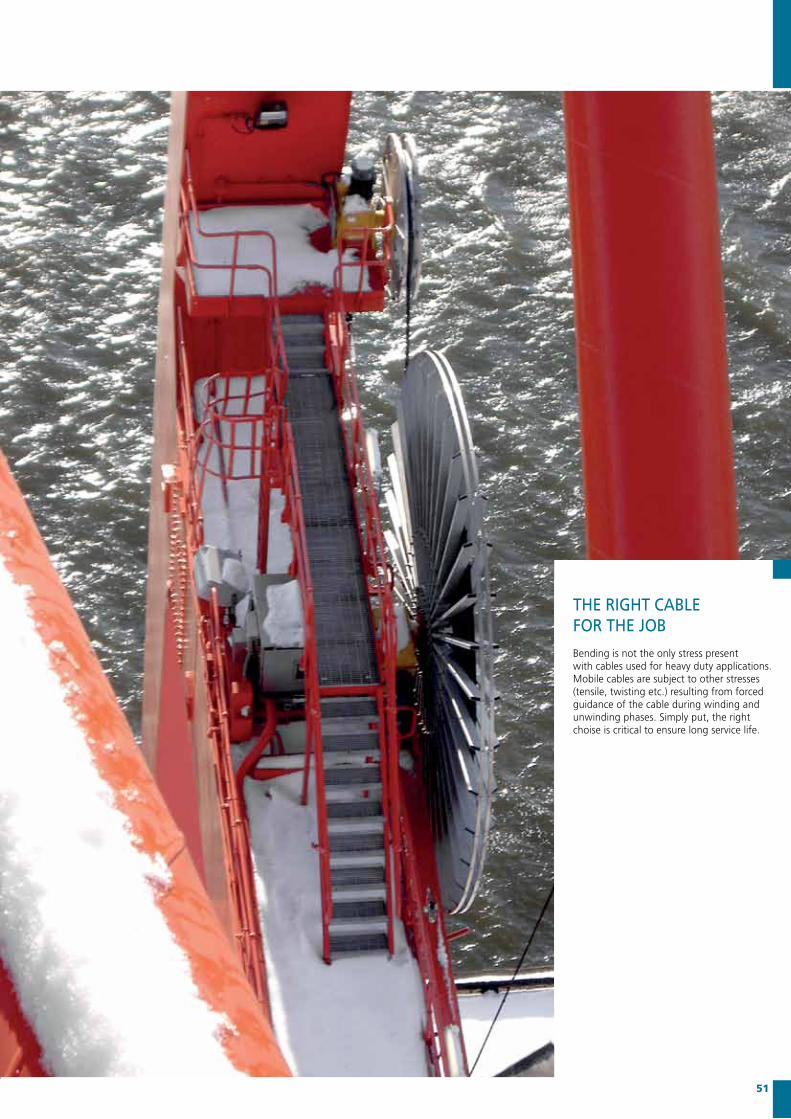
ThE RIGhT CABLEFOR ThE jOBBending is not the only stress present with cables used for heavy duty applications. Mobile cables are subject to other stresses (tensile, twisting etc.) resulting from forced guidance of the cable during winding and unwinding phases. Simply put, the right choise is critical to ensure long service life.

CABLE hANDLING
INSTALLATION INSpREADER-BASkETS
Storing and handling cables on their original drums is recommended in order to prevent defects. Avoid rolling drums; either on level or uneven ground. If the application and working conditions allow, it is preferable to roll out the cable along the line of movement of the machine prior to installation. This allows checks to be carried out to ensure cables are free from torsions and twists.
Appropriate equipment, (rollers or pulley devices), should be used to erradicate the risk of round cables (especially multi-core models) spiralling. At this stage, any longitudinal twists should be removed ensuring the cable rewinds correctly on the reel, or is properly festooned. Longitudinal reference markings on our cables make this a straight forward operation.
With cables designed for installation in baskets, the right hand lay-up of the cores means that cables must be introduced into the bottom of the basket, coiling anti-clockwise, unwinding from the outer layer of the original drum. In order to facilitate basket coiling and uncoiling operations, the outer surface of the cable should be periodically lubricated with a suitable product (such as silicone grease) designed to prevent any adhesion of dirt, dust or other matter.
52 Flexible Cables

TRANSFERONTO REELS
If working conditions prevent our recommended method is, the cable should be transferred directly from the original drum to the cable reel. Undesired twists and torsions that have a negative effect on the cable should be eliminated during this operation.
The transfer must be direct, with no intermediate guides, (rollers pulleys, twin-directional rollers etc.), and with no changes of direction or inversions of the original direction of winding on the delivery drum (see Figure 1).
Most cables are manufactured with right-hand lay-up of the conductors (both for power and control cables). It is important to remember therefore that when winding onto multispiral reels the first turn must be with the cable against the right flange of the reel. This will have the effect of exploiting the natural tendency of a cable under traction to move to the right and will keep subsequent turns tight (see Figure 2).
Transfer of cable from original delivery drum Ato the cable winding reel B.
Winding of cable onto multi-spire reel
53
Wrong method Right methodWrong method Right method
A A
B
Wrong method
B
A
B5 m
Right method
A A
B
Wrong method
B
A
B5 m
Right method
Figure 1
Figure 2

Cavotec’s service teams support your installation, commissioning and maintenance requirements, and are available around the clock to deliver on- or off-site assistance.
We also provide on-site commissioning and training, as well as dedicated training classes at our own Centres of Excellence. Using in-depth manuals and system documentation, our highly qualified engineers provide all training levels and maintenance instruction, according to your operational requirements.
Installation & Maintenance
SERvICE AND SUppORT
54 Installation & Maintenance
ExpERT CLIENT SERvICE IS A CRITICAL COmpONENT OF CAvOTEC’S AppROACh.
OUR SALES OFFICES, LOCATED AROUND ThE wORLD, ARE BACkED By OUR CENTRES OF ExCELLENCE, whERE OUR ENGINEERS ARE pOSIED TO RESpOND TO ANy SERvICE AND SUppORT REqUEST.

ABBAker SolutionsPort of AntwerpAPLAPM TerminalsBPBritish Royal NavyPort of Buenos AiresPort of BuzanPort of ChennaiChina Shipping LinesContship/EurokayDoosan Heavy Ind.DPWorldCochinJNPTPort of DubaiPort of El CallaoPort of EvergladesEvergreenFantuzzi-ReggianePort of FelixstoweFels craneFMC TechnologiesPort of Gioia TauroPort of GothenburgPort of GuanghzouPort of HamburgPort of HeidlandPort of Helsinki Port of Ho Ci MinhPort of Hong KongHyundai Heavy IndustryImpsa
Italia MarittimaKalmarKochKonecranesKuwait oil CoPort of Long BeachPort of Los AngelesMacGregorMAERSK DrillingMaher TerminalPort of ManzanilloMatson ShippingPort of MiamiMitsubishi Heavy IndustryMitsuiMOLMSCPort of MumbaiNational OilwellPort of NingboNoellNYKOdimPort of PiraeusP.S.A.QatarPetroleumCoPortofQingdaoPort of RotterdamPort of SalalahSamsungPort of San AntonioPort of Santos
SeawellSiemensPort of SingaporePort of ShanghaiPort of ShenzhenStatoilHydroPort of St LaurenceStora EnsoPort of St PetersburgPort of StockholmSTX ShipyardSumimotoSwedish NavyTechintPort of TianjinTTSU.S. Coast GuardU.S. NavyPort of VancouverPort of VirginiaYang MingZPMC
CAvOTEC IN ACTION - AROUND ThE GLOBE
Reference List 55
ACROSS OUR mARkET UNITS AND AROUND ThE GLOBE,
CAvOTEC SEEkS TO DELIvER SAFE, RELIABLE, COST-EFFICIENT AND SUSTAINABLE SOLUTIONS.
Reference List

For more information please visit our website www.cavotec.com or contact us directly at [email protected]
may
201
1 –
x2E
N –
pO
RTS
– 03
we are present in:
with a global presence of sales and manufacturing companies across six continents, Cavotec ensures each of our clients receives personal and local service.
Cavotec’s creativity and professionalism is founded on teamwork: working closely with clients, exchanging knowledge and ideas.
AustraliaBahrain Belgium Brazil Canada Chile China Denmark Finland
France Germany Greecehong kong India Ireland Italy LebanonLuxemburg
The Netherlands New zealand Norway peruqatar Russia Singapore South AfricaSouth korea
SpainSweden Switzerland U.A.E. U.k. U.S.A.