pose estimation of periacetabular osteotomy fragments with ... · pose estimation of periacetabular...
TRANSCRIPT

ACCEPTED FOR PUBLICATION IN IEEE TRANSACTIONS ON BIOMEDICAL ENGINEERING, VOL. XX, NO. XX, XXXX 2019 1
Pose Estimation of Periacetabular OsteotomyFragments with Intraoperative X-Ray Navigation
Robert B. Grupp, Rachel A. Hegeman, Ryan J. Murphy, Clayton P. Alexander, Yoshito Otake,Benjamin A. McArthur, Mehran Armand, and Russell H. Taylor, Life Fellow, IEEE
Abstract— Objective: State of the art navigation systemsfor pelvic osteotomies use optical systems with externalfiducials. We propose the use of X-Ray navigation for poseestimation of periacetabular fragments without fiducials.Methods: A 2D/3D registration pipeline was developed torecover fragment pose. This pipeline was tested throughan extensive simulation study and 6 cadaveric surgeries.Using osteotomy boundaries in the fluoroscopic images,the preoperative plan is refined to more accurately matchthe intraoperative shape. Results: In simulation, averagefragment pose errors were 1.3°/1.7 mm when the plannedfragment matched the intraoperative fragment, 2.2°/2.1 mmwhen the plan was not updated to match the true shape,and 1.9°/2.0 mm when the fragment shape was intraop-eratively estimated. In cadaver experiments, the averagepose errors were 2.2°/2.2 mm, 3.8°/2.5 mm, and 3.5°/2.2mm when registering with the actual fragment shape, apreoperative plan, and an intraoperatively refined plan, re-spectively. Average errors of the lateral center edge anglewere less than 2° for all fragment shapes in simulation andcadaver experiments. Conclusion: The proposed pipelineis capable of accurately reporting femoral head coveragewithin a range clinically identified for long-term joint sur-vivability. Significance: Human interpretation of fragment
This work was supported by NIH/NIBIB grant R21EB020113,MEXT/JSPS KAKENHI 26108004, and Johns Hopkins University Inter-nal Funds.
R. B. Grupp and R. H. Taylor are with the Department of Com-puter Science, Johns Hopkins University, Baltimore, MD, USA. (e-mail:[email protected], [email protected]).
R. A. Hegeman is with the Research and Exploratory DevelopmentDepartment, Johns Hopkins University Applied Physics Laboratory,Laurel, MD, USA. (e-mail: [email protected])
R. J. Murphy was with the Research and Exploratory DevelopmentDepartment, Johns Hopkins University Applied Physics Laboratory,Laurel, MD, USA. He is now with Auris Surgical Robotics.
C. P. Alexander is with the Department of Orthopaedic Surgery, JohnsHopkins Medicine, Baltimore, MD, USA. (e-mail: [email protected])
Y. Otake is with the Graduate school of Information Science, NaraInstitute of Science and Technology (NAIST), Nara, Japan (e-mail:[email protected]).
B. A. McArthur was with Washington Orthopedics and SportsMedicine, Chevy Chase, MD, USA. He is now with the Dell MedicalSchool, University of Texas, Austin, TX, USA and Texas Orthopedics,Austin, TX, USA.
M. Armand is with the Research and Exploratory Develop-ment Department, Johns Hopkins University Applied Physics Lab-oratory, Laurel, MD, USA and the Department of Mechanical En-gineering, Johns Hopkins University, Baltimore, MD, USA. (e-mail:[email protected])
This paper has supplementary downloadable material available athttp://ieeexplore.ieee.org, provided by the authors (File size: 111 MB).
Copyright (c) 2019 IEEE. Personal use of this material is per-mitted. However, permission to use this material for any other pur-poses must be obtained from the IEEE by sending an email to [email protected]. DOI: 10.1109/TBME.2019.2915165
pose is challenging and usually restricted to rotation abouta single anatomical axis. The proposed pipeline providesan intraoperative estimate of rigid pose with respect toall anatomical axes, is compatible with minimally invasiveincisions, and has no dependence on external fiducials.
Index Terms— 2D/3D Registration, Orthopedics, Periac-etabular Osteotomy, X-Ray Navigation
I. INTRODUCTION
DEVELOPMENTAL hip dysplasia (DDH) is a congenitalcondition which may cause greater contact pressures
between the femoral head and acetabular cartilage due toa deformed acetabulum or femoral head. These conditionsmay cause pain and limit the amount of physical activity anindividual may perform. When DDH is not addressed, severearthritis by age 30 is typical, and requires surgical intervention[1].
In 1984, the periacetabular osteotomy (PAO) was developedby Ganz for the purpose of treating DDH [2]. StandingAP and false profile radiographs are used to preoperativelyassess the condition and develop an initial surgical plan.Osteotomies along the pubis, ilium, ischium, and posteriorcolumn of the pelvis are performed, typically with fluoroscopicguidance [2]. The ischial and posterior cuts present significantchallenges, including using difficult to interpret fluoroscopicviews, potentially affecting the Sciatic nerve, and risking jointbreakage due to the osteotome’s proximity to the acetabulum.After completing the osteotomies, the acetabular fragment isfreed from the pelvis and repositioned to increase femoralcoverage and improve joint contact pressure [2]–[6] (Fig. 1).
Mentally resolving the 3D pose of the acetabular fragmentusing intraoperative fluroscopy is challenging, especially fornovice surgeons [7]. An acceptable repositioning is oftendetermined using the lateral center edge (LCE) angle [8],which estimates the amount of lateral femoral head coverageprovided by the acetabulum. In order to achieve long-termsurvivability of the joint, a LCE angle between 30° − 40°is desired [9]. Mentally resolving the LCE angle from 2Dradiographs, without any other tools, was shown to have alarge variance [10].
To address the challenges with performing PAO, severalcomputer assisted systems using optical tracking technologyhave been developed; e.g. [11]–[16]. However, intraopera-tive optical tracking systems are not yet standard equipment
arX
iv:1
903.
0933
9v2
[cs
.CV
] 9
May
201
9

2 ACCEPTED FOR PUBLICATION IN IEEE TRANSACTIONS ON BIOMEDICAL ENGINEERING, VOL. XX, NO. XX, XXXX 2019
Fig. 1. Example of periacetabular osteotomies and a fragment repo-sition. This is taken from the cadaver experiments and represents theground truth fragment pose. The manually segmented fragment shapeis shown. See Fig. 3 for the corresponding intraoperative fluoroscopicimages. The orientations of each anatomical axis for the anterior pelvicplane are also depicted: left/right x axis (LR), inferior/superior y axis (IS),and anterior/posterior z axis (AP).
in most operating rooms, and have several technical disad-vantages, such as a sensitivity to occlusion and a limitedworkspace. Moreover, the need to digitize points on the iliumand iliac crest for registration of the patient’s pelvis to apreoperative model, requires more invasive incisions thantypically needed for a PAO [12], [17], [18]. These reasons,and the universal availability of intraoperative fluoroscopicimaging, provide motivation for the use of an X-Ray basednavigation system. In place of specialized 3D tracking de-vices, computer-assisted X-Ray navigation systems use thefluoroscopic or radiographic imagers already present duringmany interventions [19]–[32]. Since the acetabular fragmentis created intraoperatively, an accurate model of the fragmentshape is not available, and invalidates the assumptions used inexisting multiple-object registration methods [22], [24], [28].
We propose a fiducialess approach that performs multiple-object, multiple-view, 2D/3D X-Ray to CT registration toresolve the pose of an acetabular fragment with respect tothe anterior pelvic plane (APP). After the clinician performsa repositioning of the fragment, the pelvis and fragmentare registered using several fluoroscopic images, and thefragment’s pose and LCE angle are reported. The fragmentshape is estimated after registering the patient’s non-acetabularportion of the pelvis. Cut lines present in the 2D images areused to approximate the ilium and pubis osteotomies, whilethe ischial and posterior osteotomies remain set accordingto a preoperative plan. The pose and LCE values may beinterpreted by the clinician to determine whether the fragmentis in an acceptable pose, or whether further adjustment isneeded. When the fragment needs to be moved, the currentpose estimate may help determine the direction in which thefragment should next be adjusted. Additionally, but beyondthe scope of this work, biomechanical indicators may also becomputed once the fragment’s relative pose is known [3]–[6].The high-level workflow of our proposal is shown in Fig. 2.
We believe this is the first computer assisted system forintraoperatively tracking an acetabular fragment with X-Raynavigation without the use of artificial fiducial objects. Com-
Fig. 2. High level workflow detailing the steps performed during thesurgery and the data required for each. The registration and shapeestimation steps are the primary focus of this paper.
pared to other multiple-view registration approaches in liter-ature, our approach does not require a tracked, encoded, ormotorized, C-Arm. Unlike existing multiple-object registra-tion solutions, an inaccurate model of the fractured shape isallowed and a prior distribution over fragment shapes is notrequired. Moreover, non-standard equipment is not required toperform the surgery and no burdensome steps are added to theoperating workflow.
We have evaluated the proposed method with a large sim-ulation study and six cadaver surgeries. In both experimentswe report fragment pose and LCE errors when knowing thetrue fragment shape, a preoperatively planned shape, and anintraoperatively estimated shape. To evaluate the performanceof our method, we examine rotation and translation compo-nents of the pose differences from ground truth, as well asthe error in LCE angle measurement. Since it is expected thatfragment pose and LCE angle errors will increase as the shapesused for registration match intraoperative shapes less, analysisof the simulation and cadaver experiments will determine ifthe proposed methods are sufficiently accurate to assist withintraoperative evaluation of dysplasia.
II. RELATED WORK
Initial work on computer aided systems for pelvic os-teotomy focused on performing the actual osteotomies, ratherthan tracking the mobilized acetabular fragment. Langlotzdemonstrated the use of preoperative CT and optically trackedsurgical instruments to assist with PAOs, but did not provideestimates on the relocated pose of the acetabular fragment[11], [33]. Mayman used optical tracking to intraoperativelyplace guiding screws on the patient’s pelvis and matchingosteotomies from a preoperative plan, but did not provide

GRUPP et al.: POSE ESTIMATION OF PERIACETABULAR OSTEOTOMY FRAGMENTS WITH INTRAOPERATIVE X-RAY NAVIGATION 3
intraoperative tracking of the fragment [13]. Akiyama alsotracked osteotomes during a curved periacetabular osteotomy(CPO) [34] using optical tracking [15]. In [35], Radermacherconstructed patient specific cutting guides for use in a tripleosteotomy [36], however the pose of the fragment was notreported during the procedure. Similarly, Otsuki developedpatient specific cutting guides to perform CPO and did nottrack the pose of the acetabular fragment [37].
Also using preoperative CT and optical tracking devices,Murphy did not track the ostoetomes, but instead tracked theacetabular movements and computed intraoperative biome-chanics [12], [38]. Through repeated digitizations of pointson the acetabular fragment body, the fragment was trackedand the appropriate biomechanical properties were presentedto the clinician [12]. Fragment pose errors of 1.4 − 1.8° and1.0−2.2 mm were reported. The process of manually digitizingthe bone bur points during each fragment reposition addsa small amount of time to the overall procedure and maybe subject to some error [38]. Liu also developed a systemfor preoperative PAO planning and intraoperative trackingof the fragment using optical tracking and a separate rigidbody attached to the fragment [14], [39]. However, fixing aseparate rigid body to the fragment is not necessarily practicalwhen using a state-of-the-art, minimally invasive, approachsuch as [17] and [18]. For rotational acetabular osteotomies(RAO) [40], Takao used an optically tracked system to monitorthe osteotomes and fragment movement [16]. The fragmentpose was intraoperatively estimated by digitizing the anterioredge of the acetabulum, which resulted in some difficultydistinguishing between rotation and translation.
X-Ray navigation has been used to assist with the reduc-tion of traumatic bone fractures, by providing real-time 3Dvisualizations of relocated bone fragments [24] and feedbackcorresponding to a 3D preoperative plan [22]. Methods toautomatically annotate intraoperative images have been usedto avoid wrong-level spinal surgery [30] and mitigate themalpositioning of surgical implants [19]. Using intraoperativeX-Ray imaging, a surgical robot may be guided into an optimallocation for the milling [23], [31], or drilling [32], of bone.Automatic 3D visualization and kinematic analysis of the wrist[20] and knee [21], [25] have also been demonstrated with X-Ray navigation. To our knowledge, no existing method basedon X-Ray navigation, without fiducials, is able to localize abone fragment without accurate preoperative knowledge or astatistical prior of the fragment shape.
At the core of an X-Ray based navigation system is a 2D/3Dregistration algorithm [26]. The goal of 2D/3D registrationis to determine the pose of 3D objects with respect to a3D coordinate frame using a series of 2D X-Ray images.Typically, a preoperative 3D model, such as a CT scan is usedto represent the patient, and the information contained in theX-Ray image is used to determine the pose of the patientwith respect to the intraoperative X-Ray imager. The majorityof 2D/3D X-Ray registration methods may be classified aseither “intensity-based” or “feature-based,” however we limitdiscussion to intensity-based methods in this paper.
Intensity-based registration performs an optimization overthe relevant pose parameters, using an objective function that
compares simulated radiographs, commonly referred to asdigitally reconstructed radiographs (DRRs), with the intra-operative image [29]. The comparison is performed using amathematical construct known as a similarity measure [29].Due to the differences in X-Ray energy between preoperativeCT and intraoperative fluoroscopy, the most effective similaritymetrics compare the 2D gradients of a measured radiographand a DRR, such as normalized cross-correlation between theSobel gradient images (Grad-NCC) [29]. Robustness to metal-lic objects and bone fractures may be improved by taking aweighted sum of similarity measures computed in local regionsof interest [41], [42]. Registration with multiple 2D views, andknown relative poses between each view, is accomplished bycreating DRRs at each view and summing the similarity scoresfor each view [27]. In order to register multiple objects withknown shape, each object may be treated as a separate volume,and DRRs for each object are summed together to createa single DRR [28]. The registration problem for N objectposes: θ1, . . . , θN , with M intraoperative views: I1 . . . IM , apre-operative CT: V , a DRR operator: P , similarity metric: S,and regularizer over plausible poses: R, is concisely stated in(1).
minθ1,...,θN∈SE(3)
M∑m=1
S
(Im,
N∑n=1
P (V ; θn)
)+R (θ1, . . . θN )
(1)With the advent of general purpose GPU programming
resources, Otake was able to efficiently form many DRRssimultaneously and use a state of the art “Covariance Ma-trix Adaptation: Evolutionary Search” (CMA-ES) optimizationstrategy [43] to carry out registration of a single femurusing three views in under 22 seconds [27]. Relative poseinformation was computed using an external fiducial for anon-motorized C-Arm and was preoperatively calibrated whenusing a motorized C-Arm.
Several groups have demonstrated registration of multipleobjects with intensity-based objective functions and accurateshape models, or with a statistical prior of the shape distribu-tions.
In [28], Otake’s framework was extended to multiple objectsfor the knee joint (distal femur, patella, proximal tibia) trackingwith bi-plane fluoroscopy. Initial registration times at the startof each sequence for the femur, tibia, and patella bones werebetween 2 and 5 minutes. All femur and tibia poses wereestimated within 2° and 2 mm, and 74% of patella poses wereestimated within the same thresholds.
Gong proposed to use intensity-based registration to intra-operatively estimate the position of bone fragments resultingfrom a distal radius fracture [22]. The approach requirespreoperative knowledge of the bone fragment shapes anduses a preoperative, but post-trauma, CT scan [22]. Two 3Dprinted phantoms with synthetic fractures were used to testthe method with four fluoroscopic views from a tracked C-Arm. Target registration errors (TREs) smaller than 3 mm wereachieved when using a manual, interactive, initialization ofthe registration. Execution times of 3-9 minutes were reportedusing modest hardware.
In order to localize and determine the shape of carpal bones

4 ACCEPTED FOR PUBLICATION IN IEEE TRANSACTIONS ON BIOMEDICAL ENGINEERING, VOL. XX, NO. XX, XXXX 2019
in the hand, Chen, et al. use a 2D/3D registration of a singlefluoroscopic view to 3D statistical shape and pose models ofthe carpal bones, radius, and ulna [20]. TREs of 2.45 mmwere reported in simulation, and TREs from 0.93−2.37 werereported in the flouroscopic experiments. Registration timeswere approximately 3 minutes per frame.
Although related by the motivation to track multiple objectswith intensity-based registration, the aforementioned works donot provide a complete solution for the localization of anacetabular fragment. Most importantly, the fragment shape isnot completely known pre-operatively and, to our knowledge,no statistical priors of pelvic osteotomies exist. In contrastto the fluoroscopic data collected of the phantom in [22],the fluoroscopic images of a human have more heterogeneoushard and soft tissue distributions, usually resulting in a morechallenging registration. Additionally, objects such as metallicscrews, wires, or tools may confound a registration strategy,and were not present in the fluoroscopic views used by [20],[22], [28].
Without any external fiducial objects or optical trackingsystems, the methods proposed in this paper intraoperativelyestimate an acetabular fragment’s pose using X-Ray naviga-tion. The pose estimation problem is solved by extendingprevious 2D/3D X-Ray registration techniques to partially es-timate the acetabular fragment shape during surgery, and thenlocalize the pelvis and fragment without a tracked, motorized,or encoded, X-Ray imager. Furthermore, our method aimsto provide intraoperative feedback in a reasonable timeframe,with computation times on the order of seconds.
III. MATERIALS AND METHODS
A. Preoperative Processing and Planning
Lower torso preoperative CT images were acquired andresampled to have 1 mm isotropic voxel spacing. Segmentationof the pelvis, and left and right femurs was performed usingan automatic method [44], followed by manual touch up. Themanual touch up was occasionally necessary to distinguishbetween the acetabulum of a pelvis and the correspondingfemoral head. Using manually annotated landmarks, the APPwas computed as described by [45] and the origin was re-located to the ipsilateral femoral head. The APP coordinateaxes are aligned with the left/right (LR), inferior/superior (IS),and anterior/posterior (AP) anatomical axes. An example ofthe APP axis orientations is shown in Fig. 1. In order toreport LCE angles intraoperatively, the most lateral pointsof the acetabulum are digitized from coronal slices of thepreoperative CT volume.
Other landmarks identified for registration purposes werethe medial and inferior points of maximal curvature on theobturator foramen, the greater sciatic notch, and inferiorsymphysis. To allow for accurate initialization of full pelvisregistration in the presence of a mobilized fragment, theregistration landmarks should not be located on portions ofthe pelvis that may become fragment.
A preoperative plan of the osteotomies is created by manualselection of several landmarks on the pelvis surface and cuttingplanes are fit to pass through the landmarks. Next, a label
Fig. 3. Top Row: Intraoperative fluoroscopic images used for registeringthe fragment on the left side of a cadaveric specimen. Note the four BBson the mobilized fragment and four BBs on the ilium used for groundtruth computation. The left image shows an approximate AP view andthe yellow circle indicates the single-landmark used for initialization ofthe intraoperative pipeline. Middle Row: DRRs created as part of theintensity-based registration using manual segmentation of the fragment;the final pose estimates are shown. Prior to performing any similaritycomparisons, the images in the top-row will be log-corrected. BottomRow: An example of simulated fluoroscopic data generated using theprotocol of the simulation study. The image includes soft-tissue andinserted K-wires, with object poses determined by the registrationsfrom the middle row. Despite the visual similarity with the top row, thechallenge of visually determining a fragment’s pose is confirmed by anapproximate 3°/3 mm pose error difference from the top row’s groundtruth. See Fig. 1 for the ground truth 3D view.
map is computed that indicates whether a voxel represents theacetabular bone fragment, the non-fragment pelvis, a portionof bone removed due to the chiseling action, left femur, orright femur. The osteotomy action is simulated by moving avirtual chisel, of width 1 mm, along the virtual cutting planesdefined by the preoperative plan. Starting from the originalsegmentation, all pelvis labels contained within the convex hulldefined by the virtual cutting planes are marked as a candidatefragment voxel. Furthermore, if a candidate fragment voxel iswithin a chisel width of any virtual cut plane, it is also markedas a candidate “cut” voxel. The set of candidate fragmentvoxels is divided into connected components, with the largestcomponent kept as candidate fragment voxels, and the othersreverted to pelvis labels. Of the remaining candidate fragmentvoxels, any marked as candidate cut voxels are labeled as cuts,and are otherwise labeled as fragment. Tight bounding boxesare computed about the pelvis labels, fragment labels, andfemur labels to create sub-volumes for each object.
B. Intraoperative Registration StrategyOur registration strategy is based on the methods described
in [27] and [28]. However, the methods proposed here do

GRUPP et al.: POSE ESTIMATION OF PERIACETABULAR OSTEOTOMY FRAGMENTS WITH INTRAOPERATIVE X-RAY NAVIGATION 5
not rely on external information to recover the multiple-view geometry, provide a quick single-landmark initialization,use a similarity metric robust to mismatches between thepreoperative models and intraoperative reality, perform a fasterlocal search at higher resolution levels, and attempt to recoverthe shape of intraoperatively created bone fragments withoutan additional CT.
DRRs are formed by ray casting through each object’sattenuation volume with a ray step size of 1 mm and trilin-ear interpolation. Grad-NCC scores are computed throughoutimage patches, with the mean value used as the similaritymeasure for all intensity-based registrations in this work [42].Ray casting and similarity metric computation are computedon a GPU through the use of OpenCL [46], while optimizationlogic is conducted on the CPU. Image parameters and theprojection geometry are derived from a Siemens CIOS FusionC-Arm with 30 cm flat panel detector. Using DICOM metadatapopulated by a CIOS Fusion, we created a naıve set of intrinsicparameters for the C-Arm: image dimensions of 1536×1536,isotropic pixel spacing of 0.194 mm/pixel, a source-to-detectordistance of 1020 mm, no distortion, and a principal point atthe center of the image.
We use two 2D image resolution levels in this work,starting from coarse (8× downsampling in each 2D dimension)and moving to a finer resolution (4× downsampling). Atthe coarsest resolution level, all optimizations are conductedwith the CMA-ES strategy, and the Bounded Optimization byQuadratic Approximation (BOBYQA) strategy [47] is used atthe second level. The CMA-ES search strategy is a derivativefree method which requires a large number of objectivefunction evaluations per iteration, but approximates a tradi-tional second-order algorithm while maintaining robustnessto local minima [43]. Since the BOBYQA strategy requiresonly a single objective function evaluation per iteration, ithas significantly faster runtimes compared to CMA-ES forthis work. Even though BOBYQA does not provide the samerobustness to local minima as CMA-ES, we justify its use atthe second resolution level due to its efficiency, and becausewe assume that pose estimates after the first resolution levellie within a smooth, convex, region about the true minima.
The C-Arm is not required to be motorized, encoded, orcapable of reporting relative pose information. In order toobtain the relative pose information required by the multi-object fragment registration, we treat the patient’s anatomy asa “fiducial” object. Single-view registrations of the pelvis areperformed for each view and the pelvis coordinate frame isthen used as the C-Arm world frame.
Assuming the first fluoroscopic view is approximately AP,a single landmark is manually annotated in 2D to initializepelvis registration. The 3D landmark location, with respect tothe C-Arm, is estimated by traversing the source-to-detectorray of this landmark 85% of the source-to-detector distance.Orientation of the pelvis is computed using the APP coordinateframe described in section III-A. Translation is recovered byaligning the landmark points in the two coordinate frames.The point of maximal curvature on the medial portion of theipsilateral obturator foramen was chosen as the initializationlandmark used in this work, and an example annotation is
shown in the top left of Fig. 3. If the first view is notapproximately AP, an initial pose estimate of the pelvis may beobtained by annotating more landmarks in 2D and solving thePnP problem [48]. Once the initial pose is estimated, a single-view intensity-based registration of the pelvis is performed.
By restricting the possible movements of the C-Arm forsubsequent views, initial pelvis pose estimates for the remain-ing views are automatically obtained through an exhaustivesearch starting from the registered pose of the pelvis in thefirst view. More precisely, we limit the geometries of theremaining views to only differ from the first view by a rotationalong the C-Arm’s orbit. DRRs are computed by adjusting theregistered pelvis pose of the initial view by C-Arm orbitalrotations of ±90° in 1° increments, for a total of 181 DRRs.Similarity computations are made between the second andthird fluoroscopic views, and the poses corresponding to thebest similarity scores are used to initialize intensity-basedregistrations. An offline calibration process was conducted todetermine center of orbital rotation and rotation axis for theCIOS Fusion.
Prior to any further registrations, the preoperative plan ofthe fragment may be refined as described in section III-C.
Once the single view pelvis registrations are complete,the multiple-view geometry is recovered using the pelviscoordinate frame and the multiple-object registration is con-ducted. Specifically, we attempt to solve problem (1) throughsuccessive optimizations of individual objects, followed by asimultaneous optimization. At each resolution level, the pelvispose estimate is refined starting from its current estimate.The pose of the pelvis is kept fixed, while an optimizationover the pose of the femur is performed. Keeping the posesof the pelvis and femur fixed, the pose of the acetabularfragment is estimated. At the coarse level, the femur andfragment poses are initialized with the current estimate of thepelvis pose, while previous poses are used for initializationat the second level. At the second level, a “simultaneous”optimization is performed after the “sequential” optimizations;which optimizes over all object poses simultaneously. Anexample of three views used for a fragment localization isshown in Fig 3.
The registration process produces pose estimates of theextrinsic C-Arm frame (C) with respect to the pelvis (PV )and fragment (FV ) volumes: TPVC and TFVC . The relativepose of the fragment with respect to the APP is computed as:
∆APP = TAPPPV TFVC TCPV TPVAPP . (2)
TPVAPP is obtained when estimating the APP from preoperativelandmarks and maps points in the APP to the preoperativepelvis and fragment volumes. Using ∆APP , the intraoperativefragment movement may be visualized in 3D (see Fig. 1) andshown to the clinician. Additional information useful for theassessment of dysplasia may also be displayed, such as theLCE angle and a decomposition of the pose with respect toeach anatomical axis. Similar to the approach in [49], the LCEangle is computed by applying the fragment’s relative pose totransform the 3D preoperative lateral trace of the acetabulum.
Given initial estimates for poses of each object, the op-timization for each object is performed over the se(3) Lie

6 ACCEPTED FOR PUBLICATION IN IEEE TRANSACTIONS ON BIOMEDICAL ENGINEERING, VOL. XX, NO. XX, XXXX 2019
Algebra [50], with the SE(3) reference point set from theinitialization point. For a single view registration, an interme-diate coordinate frame that is axis aligned with the cameraprojection frame, with origin at the initial estimate of thefemoral head, is used. For multiple view registrations, theAPP with origin at ipsilateral femoral head is used as anintermediate frame during the optimization. To discourageimplausible poses, regularization is applied when using theCMA-ES optimization strategy. For single view registrations,regularization is applied separately to each translation com-ponent and the Euler decompositions of the rotation matrix,whereas the total rotation and translation magnitudes are usedfor multiple view registrations. Box constraints are used forall optimizations using the BOBYQA optimization strategy.Since the pelvis is initially registered with single-views, theoptimization parameters used during the multi-view/multi-object registration for the pelvis are set for quicker executiontime and tighter constraints in comparison to those used toregister the femur and fragment.
Exact parameter values are listed in supplementary sectionB.
C. Fragment Shape Estimation
Since the fracture line introduced during bone chiseling isdependent on bone quality, the cut does not always follow aplanned path. Therefore, it is not realistic for a clinician toexactly reproduce the planned cuts, even when the osteotomeis guided by a navigation system. To account for the potentialuncertainties associated with the osteotomies, we have devel-oped a method to estimate the fragment shape; starting from apreoperative plan and refined from intraoperative fluoroscopicimages.
For each osteotomy to be estimated, a post-osteotomyfluoroscopic view clearly showing the cut lines is required. Thefull pelvis shape is registered to this view and a user manuallyannotates 2D pixels along the cut lines visible on the mainpelvis object. For each 2D label, a ray is cast from the C-Armdetector towards the X-Ray source, and the 3D intersectionpoints with the pelvis surface are computed. The osteotomy isestimated by fitting a plane to the recovered 3D points. Whenlooking approximately down the cut line, the ray is nearlytangent to the entire cut and 3D intersection points enteringand leaving the pelvis surface are used. Otherwise, a labelmust indicate whether the ray intersects the 3D osteotomywhen entering or exiting the pelvis surface; in this case onlythe entry or exit intersection point is used. Fig. 4 shows anexample of the 2D labeling of ilium and pubis cut pixels.
If an appropriate view and corresponding pelvis registrationis not available, then the preoperative plan for that osteotomyis used for shape estimation. For the ischial and posteriorosteotomies, it is challenging to obtain a view that clearlyshows the cut lines, and for which a pelvis registration maybe successfully performed. Therefore, only the ilium and pubisosteotomies will be estimated in the following experiments,and the ischium and posterior osteotomies will be set at theplanned values.
Fig. 4. An example of the 2D cut manual annotations from fluoroscopicimages corresponding to the case shown in Fig. 1. Labels identifyingilium cuts are shown in (a), and labels identifying pubis cuts are shownin (b). Zoomed displays of the regions of interest in (a) and (b) are shownin (c) and (d), respectively. In (a) and (c) biege labels indicate rays thatenter the pelvis surface when moving from the detector to source, whileblue labels indicate rays that exit the pelvis surface. In (b) and (d), redlabels indicate rays that both enter and exit the pelvis surface; the viewlooks approximately down the cut line.
D. Simulation Study
In order to determine the feasibility of this registrationstrategy, we conducted a large simulation study using the CTscans of 6 non-dysplastic cadaveric specimens. The groupof specimens consisted of 4 male and 2 female subjects,with ages ranging from 57 to 94 years (81 ± 14). For theleft and right sides of each specimen, we created simulatedacetabular fragments, simulated fragment movements, andsimulated intraoperative fluoroscopic images.
All PAOs were performed bilaterally by a single surgeon(B.A.M.). In order to create nominal fragment shapes, planeswere fit to the osteotomy contours in postoperative CT vol-umes and then mapped into preoperative CT coordinates.Random surgeries were simulated by applying random rigidtransformations to the cutting planes associated with eachnominal osteotomy. The random adjustments were manuallyverified to create plausible PAO fragments and any invalidfragments were rejected. This resulted in 15 simulated frag-ments for each side of each patient and 180 for the entirestudy.
Random movements of each fragment and ipsilateral femurwere sampled. Random rotations of the fragment and femurwere sampled along with a random translation component forboth the fragment and femur. The translation component isshared, since the fragment and femur tend to move together.To mimic clinically relevant movements of the fragment andfemur, Euler angles and translations about each anatomicalaxis were sampled. All transformations are with respect tothe APP with appropriate femoral head origin. Collision de-tection was performed to ensure that different bones did not

GRUPP et al.: POSE ESTIMATION OF PERIACETABULAR OSTEOTOMY FRAGMENTS WITH INTRAOPERATIVE X-RAY NAVIGATION 7
overlap in 3D space. When a collision occurred, the set oftransformations was rejected, and another set was sampled. Atotal of 20 movements for each fragment were sampled, witha mean rotation of 15.49° ± 6.77° and mean translation of4.35 mm ± 1.57 mm. This yields a total of 3, 600 fragmentmovements for this study.
Three views are used for each repositioned fragment: aperturbed AP view, followed by two views offset at randomrotations about the C-Arm’s orbit. The simulated fluoroscopyincorporates soft-tissues by piece-wise rigidly warping theoriginal CT volume according to the pelvis, femur, and frag-ment labels as described in [42]. A temporary fixation of thefragment is simulated by inserting two random K-wires intothe volume, each at a random pose intersecting the ilium andfragment. Using a protocol similar to [51], fluoroscopic imagesare created from this new volume and view geometries. Anexample set of simulated fluoroscopic images is shown in thebottom row of Fig. 3.
The registration process proceeds according to the strategydescribed in III-B. Registrations are initialized by simulatinga 2D and 3D point picking process for the single landmarkstrategy. Using the registration point manually identified ineach CT, the corresponding 2D pixel location is computedfor each set of fluoroscopic views. Random noise is addedto the 2D and 3D points to simulate variation in humanpoint picking behavior. The landmarks are offset by a randomdistance along a random direction. The offset directions aredrawn uniformly from the appropriate (2D or 3D) sphere. The3D offset magnitudes are sampled, in mm, from N(0, 3), andthe 2D magnitudes are sampled, in pixels, from N(0, 7.5).Five different initializations are estimated for each set offluoroscopic views.
These simulations result in a total of 18, 000 multiple-object/multiple-view registrations that need to be evaluated.Each registration is run over four scenarios; each with adifferent fragment shape used during the registration. Thefirst case considered is when the fragment shape in thefluoroscopic views exactly matches the preoperative plan. Wealso considered the case of tracking a fragment with anunknown, or uncertain shape. To achieve this we assumedthat the nominal fragments represent preoperative plans forthe randomly adjusted fragments present in the simulatedfluoroscopic images. The remaining two cases examined theeffect of using intraoperative information to update the plannedcut model. For the first case of incorporating intraoperativeknowledge, it was assumed that the ilium and pubis os-teotomies would be perfectly recovered; the planned ilium andpubis cuts were replaced with the actual values. In the secondcase, synthetic 2D cut annotations were used to simulate thefragment shape estimation described in section III-C.
Further details regarding the simulated datasets are de-scribed in supplementary section D.
E. Cadaver Study
In order to further evaluate the proposed methods, intra-operative fluoroscopy was collected during six of the PAOspreviously used for simulation studies. Four specimens, three
Fig. 5. Intraoperative setup for the PAO procedure performed on theright side of a cadaveric specimen. The current fluoroscopic view isshown in the bottom left. The enlarged region in the top right showsthe markings used to control the orbital rotation of the C-Arm.
male and one female, were used. Each surgery was performedunder fluoroscopic guidance with a Siemens CIOS Fusion C-Arm with 30 cm flat panel detector. Fig. 5 shows a photographof the operating theater. Each fluoroscopy image of the repo-sitioned fragments contains screws, K-wires, or a combinationof the two.
Fragment registrations were evaluated using the true frag-ment shape, preoperative planned fragments, and intraopera-tively estimated fragment shapes. Postoperative CT scans weretaken, and the fragment shape was manually segmented, toobtain the true fragment shape. Fifteen preoperative plans foreach surgery were created by fitting cutting planes to themanually segmented fragment, followed by random adjust-ments. Each preoperative plan was manually verified to bea valid PAO, with any invalid plan rejected and resampled.The 2D cut lines of the ilium and pubis osteotomies weremanually annotated in the fluoroscopic images, and were usedto compute the ilium and pubis cutting planes of the estimatedfragment shape. Each estimated shape is completed with theplanned ischium and posterior osteotomies.
Included with this paper is a supplementary video1, whichillustrates the workflow used to perform the fragment shapeand pose estimation for the left side of the specimenshown in Figures 1, 3, 4, and 5. This will be available athttp://ieeexplore.ieee.org.
Ground truth poses of each fragment were obtained usingmetallic BBs implanted into the pelves. The postoperativeCT volumes contain the relocated fragment which had beenintraoperatively fixed in place using screws and K-wire. Priorto osteotomy, BBs were implanted onto the interior iliumsurface in a region expected to lie on the fragment, andadditional BBs were implanted onto the interior ilium surfacein a region expected to not lie on the fragment. The groundtruth fragment poses are calculated with 3D/3D paired-pointregistrations [52] between the 3D locations of the fragmentBBs before osteotomy, and the 3D locations after osteotomy.For two specimens, and three PAOs, the fragment BB locations
1https://youtu.be/pXmVa3-MJXo

8 ACCEPTED FOR PUBLICATION IN IEEE TRANSACTIONS ON BIOMEDICAL ENGINEERING, VOL. XX, NO. XX, XXXX 2019
were computed using 3D CT imaging only. Eight BBs wereplaced on the ilium region and another eight placed on thefragment, with each eight BB constellation made of four 1.5mm diameter BBs and four 1 mm diameter BBs. A HalifaxBiomedical Inc. injection device was used to insert the 1mm diameter BBs. One of our clinical co-authors, C.P.A.,inserted these BBs after performing soft-tissue dissections. Anadditional preoperative CT of the specimens was obtained torecover the pre-osteotomy BB locations. For the remainingtwo specimens, and remaining three PAOs, four BBs (1.5mm diameter) were inserted on the ilium region and fourBBs (1.5 mm diameter) inserted on the fragment region. Noadditional preoperative CT was obtained, however a seriesof fluoroscopic images were taken prior to osteotomy. Usingthe BB constellations obtained from the postoperative CT,the pre and post-osteotomy 3D locations of the BBs wereobtained through a series of 2D/3D landmark registrations onthe fluoroscopic images. A similar approach, using a plasticpelvis phantom with injected BBs and three views from CBCTprojections, showed that the fragment pose may be recoveredwithin 1°/1 mm of CBCT ground truth [53], [54]. Details ofBB insertion and the methods used to obtain ground truthposes are described in supplementary section E. The BBs werenot present in the preoperative CTs used to drive the intensity-based registrations and did not aid the proposed methods inany way.
IV. RESULTS
A. Simulation Study
Fragment pose estimation was most accurate when the exactfragment shape was used during registration, and accuracymonotonically decreased as knowledge of the shape decreased.For each simulation in which the osteotomies were at leastpartially known or estimated, the mean rotation and transla-tion errors were less than 2° and 2 mm, respectively. Meanfragment pose errors of 2.2° and 2.1 mm were obtained fromthe simulation using preoperatively planned shapes. For allfragment shapes, mean LCE errors were less than 1°. TableI lists the mean and standard deviations of the fragmentpose and LCE errors for each simulation study. Fig. 6 showsthe joint histograms for the fragment pose estimation errors.The shape of the error distribution “widens” as the amountof uncertainty associated with the fragment shape increases,particularly with respect to rotation error. The percentages ofregistrations with rotation errors below 3° were 96%, 83%,92%, and 91%, for the cases of all cuts known, no cutsknown (preoperatively planned), known ilium and pubis cuts,and estimated ilium and pubis cuts, respectively. Similarly, thecorresponding percentages of trials with LCE errors below 3°were 99%, 97%, 98%, and 98%.
Single-tailed Mann-Whitney U-Tests were performed to de-termine any statistical significance between the errors obtainedwhen running registration with different fragment shapes. Thep-values are shown in Table II, and indicate that pose andLCE estimation errors associated with the various categories offragment shape are statistically different. Moreover, the single-tailed test indicates that the errors associated with fragment
shapes using less intraoperative osteotomy information arestatistically larger than errors determined by fragment shapesincorporating more knowledge of the intraoperative cuts.
B. Cadaver StudyA summary of the fragment pose and LCE error statistics
is provided in Table III. Two results, one correspondingto a planned fragment shape and another to an estimatedshape, produced fragment rotation errors above 20° and werediscarded from analysis. The pose estimations with manualsegmented fragments, planned fragments, and estimated frag-ments resulted in mean rotation/translation errors of 2.2°/2.2mm, 3.8°/2.5 mm, and 3.5°/2.5 mm, respectively. Mean LCEerrors were below 2° for all fragment shapes. Additionally,the standard deviations of all rotation and LCE errors strictlyincreased as knowledge of the fragment’s 3D shape decreased.Rotation errors were less than 3° for 83%, 39%, and 39% ofthe registration trials when using a manual segmentation ofthe fragment, a planned fragment, and an estimated fragment,respectively. The corresponding proportions of LCE errors lessthan 3° were 100%, 85%, and 85%.
Table IV shows p-values from statistical tests of significanceconducted on the rotation, translation, and LCE errors. Theprotocol was identical to that used for evaluating the simula-tion study results. Using a threshold of p = 0.005, no statisticaldifferences are indicated between the rotation, translation, orLCE errors when comparing the various fragment shapes.
The single-landmark initialization strategy was used for fourof the six cases, and multiple-landmark initialization was usedfor the remaining two. In the two cases requiring multiple-landmark initialization, the initial views were taken with thedetector parallel to the operating table and did not match atypical AP view due to the pelvic tilt of the specimens.
An expected runtime of 25.3 seconds was obtained byre-running the estimated-fragment pose estimation pipeline20 times for each surgery. The expected time required tomanually choose a single 2D landmark, required for regis-tration initialization, was 2 seconds; the expected time formanual annotation of 2D cut lines, required for fragment shapeestimation, was 51.2 seconds.
The ground truth fragment poses from each surgery, theerror statistics for each individual surgery, violin plots of theerror distributions, and a breakdown of timings across theindividual components of the registration pipeline are providedin supplementary section G.
V. DISCUSSION
The simulation study yielded promising results for thelocalization of the acetabular fragment. As one would ex-pect, the pose errors were smallest on average when theexact shape of each bone was known during registration,and degraded as less information about the osteotomies wasknown. This increase in average error was consistent acrosstotal rotation and translation magnitudes, the decompositionsabout anatomical axes, and for the LCE angle estimates. Theincreases in rotation error magnitudes and LCE angle errorswere statistically significant for all comparisons and highlight

GRUPP et al.: POSE ESTIMATION OF PERIACETABULAR OSTEOTOMY FRAGMENTS WITH INTRAOPERATIVE X-RAY NAVIGATION 9
TABLE ISIMULATION STUDY FRAGMENT AVERAGE POSE AND LATERAL CENTER EDGE ANGLE ERRORS
Study Rotation (°) Translation (mm) LCE (°)AP LR IS Total AP LR IS TotalAll Cuts Known 0.47± 1.48 0.73± 1.35 0.67± 1.14 1.25± 2.24 1.54± 1.29 0.32± 0.59 0.43± 0.59 1.73± 1.42 0.50± 1.53No Cuts Known 0.60± 1.62 1.53± 1.77 1.07± 1.29 2.19± 2.58 1.84± 1.46 0.38± 0.63 0.50± 0.58 2.05± 1.56 0.88± 1.72Ilium & Pubis Known 0.50± 1.59 1.07± 1.64 0.83± 1.28 1.63± 2.54 1.74± 1.38 0.33± 0.61 0.49± 0.60 1.94± 1.49 0.61± 1.66Ilium & Pubis Est. 0.58± 1.67 1.16± 1.78 1.00± 1.24 1.86± 2.62 1.75± 1.48 0.34± 0.57 0.49± 0.57 1.96± 1.56 0.73± 1.82Means and standard deviations of the fragment pose errors and lateral center edge (LCE) angle errors for each simulation study. The errors areorganized by the type of fragment shape used for pose estimation, the total rotation and translation error magnitudes, the decompositions of the errorsabout each anatomical axis, and the LCE angle. Small LCE errors for all fragment shapes indicate that any shape is reliable for reporting lateralcoverage of the femoral head.
Fig. 6. Normalized 2D histograms of fragment pose error for the simulation studies. (a) The actual fragment shape is known and matches theplanned fragment shape, (b) the actual fragment shape is not known and none of the osteotomies match the planned fragment, (c) the actualfragment is partially known, with the ilium and pubis osteotomies matching the planned fragment, (d) the actual fragment is not known, but the iliumand pubis osteotomies are estimated from 2D cut lines.
TABLE IISIMULATION STUDY STATISTICAL TEST RESULTS
Fragment Shapes p-Value1 2 Rot. Trans. LCE
All Cuts Known No Cuts Known < 10−6 < 10−6 < 10−6
All Cuts Known Ilium & Pubis Known < 10−6 < 10−6 < 10−6
All Cuts Known Ilium & Pubis Est. < 10−6 < 10−6 < 10−6
Ilium & Pubis Known Ilium & Pubis Est. < 10−6 0.74 < 10−6
Ilium & Pubis Est. No Cuts Known < 10−6 < 10−6 < 10−6
Results of the Mann-Whitney U-Tests on fragment pose errors for thesimulation studies. The total rotation and translation magnitudes of thepose errors, along with the error of the lateral center edge (LCE) angleare examined. The null hypothesis indicates that both sets of errors aredrawn from the same distribution with identical medians and the alternativehypothesis indicates that the errors are drawn from different distributionswith the second distribution (fragment shape with label 2) having largermedian. Applying a threshold of 0.005 to the above p-values results in arejection of the null-hypothesis for all but one of the tests. This implies thaterrors associated with fragment shapes incorporating less information of thetrue cuts are statistically larger than the errors associated with cuts that moreclosely match intraoperative cuts, except when comparing translation errorswhen ilium and pubis cuts are known versus estimated.
the impact of preoperative/intraoperative fragment shape mis-match on registration accuracy. Increases in the translationerror magnitudes were statistically significant in all but onecomparison: using true pubis and ilium osteotomies, mixedwith planned ischial and posterior osteotomies, compared withestimating the pubis and ilium osteotomies. This also indicatesthat the fragment localization is partially robust to differencesbetween the planned and intraoperative osteotomies for theischial and posterior cuts.
To our knowledge, no bounds on the accuracy of fragmentpose or LCE angle have been identified in previous literature,therefore we consider 3° to be an acceptable upper bound
on LCE angle error. This threshold allows the clinician totarget LCE angles between 33°−37°, while having confidencethat the true LCE angle is within the 30° − 40° criteria putforth by [9]. At this threshold, the lowest success rate of 97%corresponds to a preoperatively planned fragment shape, andindicates that an arbitrary preoperative plan is sufficient toobtain a successful registration. However, if the LCE errorthreshold is lowered to 2°, successful pose estimates werefound in 98%, 92%, 97%, and 96% of trials, for the casesof the fragment shape with all cuts known, the preoperativelyplanned fragment shape, the shape with known ilium andpubis cuts, and the shape with estimated ilium and pubis cuts,respectively. Therefore, a clinician may attach more confidenceto pose estimates obtained after estimating the fragment’silium and pubis cuts.
In cadaver surgeries, registrations using each fragment shapeyielded average LCE errors less than 2°. This indicates thatthe proposed pipeline is capable of producing clinically usableestimates on real fluoroscopic imagery. In terms of averagerotational and LCE error, registrations using the manuallysegmented fragment shape outperformed registrations usingpreoperatively planned shapes and intraoperatively refinedshapes. However, when examining translation dimensions, themanually segmented fragment did not offer a noticeable advan-tage over the remaining two shapes. The performance acrossall error metrics was roughly equivalent when comparingthe registrations using the preoperative plan and estimatedfragments. Moreover, when comparing the errors producedthrough registrations using differing shape types, no statis-tically significant differences were found. This is in starkcontrast to the simulation study results, which imply that

10 ACCEPTED FOR PUBLICATION IN IEEE TRANSACTIONS ON BIOMEDICAL ENGINEERING, VOL. XX, NO. XX, XXXX 2019
TABLE IIICADAVER EXPERIMENT FRAGMENT POSE AND LATERAL CENTER EDGE ANGLE ERRORS
Study Rotation Errors (°) Translation Error (mm) LCE (°)AP LR IS Total AP LR IS TotalMan. Seg. 0.51± 0.25 1.76± 0.93 1.02± 0.51 2.22± 0.73 1.22± 0.50 1.03± 0.79 1.29± 1.01 2.18± 1.10 1.08± 0.52Planned 1.17± 1.10 2.59± 1.70 1.89± 1.48 3.77± 1.88 1.49± 1.40 1.06± 0.90 1.16± 0.99 2.48± 1.51 1.80± 1.39Estimated 0.98± 0.80 2.62± 1.38 1.55± 1.21 3.46± 1.47 0.98± 0.83 1.07± 0.83 1.15± 0.90 2.17± 0.94 1.80± 1.18Means and standard deviations of fragment pose and lateral center edge angle (LCE) errors for the cadaver surgeries. For each type of fragment shapeused during registration, the total rotation and translation error magnitudes are reported, along with the errors about each anatomical axis and the LCEangle error. The manual segmented fragment shape, planned fragment shape, and estimated fragment shapes roughly correspond to the simulationcases of a fragment shape with all cuts known, a preoperatively planned fragment shape with no cuts known, and a shape with ilium and pubis cutsestimated, respectively, as shown in Table I.
TABLE IVCADAVER EXPERIMENTS STATISTICAL TEST RESULTS
Fragment Shapes p-Value1 2 Rot. Trans. LCE
Man. Seg. Planned 0.0194 0.3798 0.1194Man. Seg. Ilium & Pubis Cuts Est. 0.0187 0.5208 0.0741Ilium & Pubis Cuts Est. Planned 0.1678 0.1023 0.7167Results of the Mann-Whitney U-Tests on fragment pose and lateral centeredge (LCE) angle errors for the cadaver experiments. See Table II for adiscussion of the hypotheses. Using a threshold of 0.005, no significantdifference is reported for any of the errors and for each comparison ofshapes.
an estimated shape should perform statistically better than apreoperatively planned fragment.
We believe this is primarily caused by low bone qualitiesfrom two specimens used for three surgeries. Prior to anyosteotomies made to free the acetabular fragment, a smallosteotomy of the anterior superior iliac spine (ASIS) is per-formed in order to provide sufficient access to the ilium. Atthe conclusion of the surgery, the ASIS is reattached in itsoriginal location. The ASIS osteotomy was excessively largefor two specimens, resulting in a fragment shape with anadditional osteotomy not representable by our four-cut model.When these three surgeries are removed from the results,100% of the registrations using manually segmented fragmentshapes, 95% using preoperatively planned fragment shapes,and 100% using estimated shapes produce LCE errors less than3°. Furthermore, mean rotation errors of the fragment posewere 2.4°, 4.0°, and 3.1° when using a manually segmentedfragment shape, a preoperative plan, and estimated shape,respectively. Although no statistical difference was found be-tween these error distributions, the results are more consistentwith the trend established by the simulation study of increasingerrors, corresponding to registrations using more mismatchedfragment shapes. Since most patients undergoing PAO areyoung adults, bone quality is not expected to be an issue inclinical use. Considering these factors, we can say that thefragment pose estimation using an estimated shape providedclinically relevant results to determine femoral head coverage,with LCE errors less than 3°.
The mean rotation error of 3.5°, when using the estimatedfragment shape during the cadaver surgeries, is noticeablylarger than the 1.8° error reported by a state-of-the-art op-tically tracked solution [12]. Translation errors found withthe proposed system are roughly equivalent to the 2.2 mmidentified by the optically tracked method. Although the X-Ray
navigation approach has inferior rotation performance com-pared to the optically tracked method, the previous analysis ofLCE angle errors indicate it is capable of providing clinicallyappropriate pose estimates.
The amount of femoral head coverage is primarily derivedfrom the series of rotations applied to the acetabular fragmentabout the femoral head. For this reason, we report errors usingrotation and translation components of the pose differencesbetween registered estimates and ground truth poses. Further-more, large TREs at regions distant from the cartilage surface,such as the ilium osteotomy, do not imply an incorrect estimateof the femoral head coverage.
Given the promising results in cadaveric experiments, andthe diversity of data used in simulation, we believe this methodshould perform well on human subjects. Although we did notevaluate the proposed methods on dysplastic hips, our methodshould not suffer any performance degradation when run ondysplastic hips of younger patients. We have not made anyassumptions in our processing specific to normal hip anatomy,and we only require an intensity volume of the pelvis thatwe may compute DRRs from. Some dysplastic hips may besubject to severe arthritis, which would likely cause difficultyduring preoperative segmentation and also create a less-smoothregistration similarity metric, however these patients wouldmost likely undergo a total hip replacement (THR) instead ofpelvic osteotomy.
The expected computation time of approximately 25 sec-onds is reasonable for intraoperative operation, however thisdoes not include the time required to perform any manualannotations. Since the fragment will not change shape afterthe osteotomies are completed, annotation of the cut linesonly needs to be performed once. It is likely that severaladjustments to the fragment’s pose will be required, thereforewe believe that the cut annotation time is amortized overeach of these adjustments. A similar amortization is notapplicable to registration re-initialization via landmark identi-fication. However, other techniques using neural networks forrecognizing fluoroscopic landmarks [55], or for approximatepose regression [56], could be applied to avoid this bottleneck.
Although implicitly penalized by the image similarity met-ric, the proposed registration method does not penalize 3Dcollision or overlap of bones. It is possible that the method’sperformance may improve by including collision and overlapinformation into the regularization term of (1). When thefragment shape used during registration does not match thetrue fragment shape, it is possible for collisions to occur,

GRUPP et al.: POSE ESTIMATION OF PERIACETABULAR OSTEOTOMY FRAGMENTS WITH INTRAOPERATIVE X-RAY NAVIGATION 11
particularly about the ischial and posterior osteotomies. There-fore, it may be possible to recover more accurate shapes by up-dating the volumetric segmentation to remove collisions afterregistration. Shapes could be refined by iteratively switchingbetween registration and shape updates.
The six cadaver surgeries have served as proof-of-conceptfor the methods proposed in this work, however we believefurther efforts should include clinical PAO cases. This wouldinclude the acquisition of clinical PAO fluoroscopic data usedfor further validation, and move towards a comparison of pa-tient outcomes and operative times of non-navigated, opticallynavigated, and X-Ray navigated cases. The system could alsointegrate a preoperative plan of the biomechanically optimalfragment reposition, and intraoperatively provide feedbackconsisting of adjustments that would maximize the likelihoodof achieving the plan.
Although the experiments in this paper were restricted toPAO, we have not made any assumptions that would precludeapplication to other pelvic osteotomies, such as RAO, CPO,or triple osteotomy. Forty percent of THR surgeries result ina mal-positioned (with respect to the “safe zone”) acetabu-lar component [57], therefore we believe that our fragmenttracking approach would also be useful for the intraoperativevisualization, and guidance, of the THR acetabular implant.
Although the use of a preoperative CT scan is an in-creasingly common practice, it is not considered the currentstandard of care at all centers. When CT scans are used fordiagnosis or preoperative planning, slice spacings are typicallyin the range of 2−3 mm [10]. It is not clear what effect lowerresolution CT data will have on the accuracy of the proposedsystem and remains an important topic to be investigated.Furthermore, higher resolution preoperative CT scans mayadd additional cost and expose the patient to, potentiallyhazardous, radiation. In the future, a “CT free” approach couldbe implemented using a statistical deformation model (SDM)created from a database of existing pelvic CTs [58]. TheSDM would be used in a deformable 2D/3D registration torecover the patient’s 3D anatomy from standard preoperativestanding radiographs and several pre-osteotomy fluoroscopicimages [59]. However, the SDM would most likely be unableto recover a sufficiently accurate cartilage model required forbiomechanical measures and analysis. This could be overcomethrough the use of a partial preoperative CT, scanning only theacetabulum and extrapolating the remaining anatomy with theSDM, similar to the methods proposed in [60] and [61].
VI. CONCLUSION
The proposed method for intraoperative localization of amobilized acetabular fragment, with uncertain shape, has beendemonstrated to report LCE angles within clinical tolerance insimulated cases and also in cadaveric cases for PAO. Less com-mon equipment used in other approaches, such as an encodedor motorized CBCT C-Arm or an optical tracking device, isnot required by this method. Additionally, the processing runsin an amount of time which is reasonable for incorporation intoan intraoperative workflow. As entry-level flat panel imagingtechnology becomes more common in operating theaters, our
method should be directly applicable to pelvic osteotomies orother similar fragment tracking tasks. The proposed X-Raynavigation could make pelvic osteotomies more accessible tonovice surgeons, reduce the number of times a fragment needsto be adjusted during a procedure, and possibly reduce theradiation exposure to the surgical team by reducing the numberof fluoroscopic images used.
ACKNOWLEDGMENT
The authors would like to thank Mr. Demetries Boston forhis assistance during cadaveric testing. Professor YoshinobuSato provided productive and insightful discourse during thealgorithmic development of this work, for which we are verygrateful. Additionally, we are indebted to Dr. Masaki Takaoand Dr. Nobuhiko Sugano for allowing us to observe an RAOprocedure and become aware of the challenges involved. Wealso thank Professor Mathias Unberath for helpful discussions.Finally, we are appreciative of the constructive comments andcritiques provided by the anonymous reviewers, which haveresulted in an improved paper. This feedback led to the single-landmark registration initialization strategy, and has greatlyimproved the system’s ease of use. This research was sup-ported by NIH/NIBIB grants R01EB006839, R21EB020113,MEXT/JSPS KAKENHI 26108004, Johns Hopkins Univer-sity Internal Funds, and a Johns Hopkins University Ap-plied Physics Laboratory Graduate Student Fellowship. Partof this research project was conducted using computationalresources at the Maryland Advanced Research ComputingCenter (MARCC).
REFERENCES
[1] S. B. Murphy, R. Ganz, and M. Muller, “The prognosis in untreateddysplasia of the hip. A study of radiographic factors that predict theoutcome.” J Bone Joint Surg Am, vol. 77, no. 7, pp. 985–989, 1995.
[2] R. Ganz et al., “A new periacetabular osteotomy for the treatment ofhip dysplasias technique and preliminary results.” Clin. Orthop. Relat.Res., vol. 232, pp. 26–36, 1988.
[3] M. Armand et al., “Outcome of periacetabular osteotomy: joint contactpressure calculation using standing AP radiographs, 12 patients followedfor average 2 years,” Acta Orthop, vol. 76, no. 3, pp. 303–313, 2005.
[4] R. S. Armiger et al., “Three-dimensional mechanical evaluation of jointcontact pressure in 12 periacetabular osteotomy patients with 10-yearfollow-up,” Acta Orthop, vol. 80, no. 2, pp. 155–161, 2009.
[5] N. Niknafs et al., “Biomechanical factors in planning of periacetabularosteotomy,” Front Bioeng Biotechnol, vol. 1, 2013.
[6] J. A. Hipp et al., “Planning acetabular redirection osteotomies based onjoint contact pressures.” Clin. Orthop. Relat. Res., vol. 364, pp. 134–143,1999.
[7] A. Troelsen, “Surgical advances in periacetabular osteotomy for treat-ment of hip dysplasia in adults,” Acta Orthop, vol. 80, no. sup332, pp.1–33, 2009.
[8] G. Wiberg, “Studies on dysplastic acetabulum and congenital sublux-ation of the hip joint with special reference to the complications ofosteoarthritis,” Acta Chir Scand, vol. 83, no. 58, 1939.
[9] C. Hartig-Andreasen et al., “What factors predict failure 4 to 12 yearsafter periacetabular osteotomy?” Clin. Orthop. Relat. Res., vol. 470,no. 11, pp. 2978–2987, 2012.
[10] A. Troelsen et al., “Assessment of hip dysplasia and osteoarthritis:Variability of different methods,” Acta Radiol, vol. 51, no. 2, pp. 187–193, 2010.
[11] F. Langlotz et al., “Computer assistance for pelvic osteotomies.” Clin.Orthop. Relat. Res., vol. 354, pp. 92–102, 1998.
[12] R. J. Murphy et al., “Development of a biomechanical guidance systemfor periacetabular osteotomy,” Int J Comput Assist Radiol Surg, vol. 10,no. 4, pp. 497–508, 2015.

12 ACCEPTED FOR PUBLICATION IN IEEE TRANSACTIONS ON BIOMEDICAL ENGINEERING, VOL. XX, NO. XX, XXXX 2019
[13] D. J. Mayman et al., “The kingston periacetabular osteotomy utilizingcomputer enhancement: a new technique,” Comput Aided Surg, vol. 7,no. 3, pp. 179–186, 2002.
[14] L. Liu et al., “Computer assisted planning and navigation of periacetab-ular osteotomy with range of motion optimization,” in Proc. Med. ImageComput. Comput.-Assist. Interv, 2014, pp. 643–650.
[15] H. Akiyama et al., “Computed tomography-based navigation for curvedperiacetabular osteotomy,” J Orthop Sci, vol. 15, no. 6, pp. 829–833,2010.
[16] M. Takao et al., “Comparison of rotational acetabular osteotomy per-formed with navigation by surgeons with different levels of experienceof osteotomies,” Int J Comput Assist Radiol Surg, vol. 12, no. 5, pp.841–853, 2017.
[17] A. Troelsen, B. Elmengaard, and K. Søballe, “A new minimally invasivetranssartorial approach for periacetabular osteotomy,” J Bone Joint SurgAm, vol. 90, no. 3, pp. 493–498, 2008.
[18] A. Troelsen, B. Elmengaard, and K. Søballe, “Comparison of theminimally invasive and ilioinguinal approaches for periacetabular os-teotomy 263 single-surgeon procedures in well-defined study groups,”Acta Orthop, vol. 79, no. 6, pp. 777–784, 2008.
[19] P. Belei et al., “Fluoroscopic navigation system for hip surface replace-ment,” Comput. Aided Surg., vol. 12, no. 3, pp. 160–167, 2007.
[20] X. Chen et al., “Automatic inference and measurement of 3D carpalbone kinematics from single view fluoroscopic sequences,” IEEE Trans.Med. Imag., vol. 32, no. 2, pp. 317–328, 2013.
[21] D. A. Dennis et al., “In vivo determination of normal and anteriorcruciate ligament-deficient knee kinematics,” J Biomechan, vol. 38,no. 2, pp. 241–253, 2005.
[22] R. H. Gong, J. Stewart, and P. Abolmaesumi, “Multiple-object 2-D–3-Dregistration for noninvasive pose identification of fracture fragments,”IEEE Trans. Biomed. Eng., vol. 58, no. 6, pp. 1592–1601, 2011.
[23] A. Gueziec et al., “Anatomy-based registration of CT-scan and intraop-erative X-ray images for guiding a surgical robot,” IEEE Trans. Med.Imag., vol. 17, no. 5, pp. 715–728, 1998.
[24] L. Joskowicz et al., “FRACAS: a system for computer-aided image-guided long bone fracture surgery,” Comput. Aided Surg., vol. 3, no. 6,pp. 271–288, 1998.
[25] M. R. Mahfouz et al., “A robust method for registration of three-dimensional knee implant models to two-dimensional fluoroscopy im-ages,” IEEE Trans. Med. Imag., vol. 22, no. 12, pp. 1561–1574, 2003.
[26] P. Markelj et al., “A review of 3D/2D registration methods for image-guided interventions,” Med Image Anal, vol. 16, no. 3, pp. 642–661,2012.
[27] Y. Otake et al., “Intraoperative image-based multi-view 2D/3D regis-tration for image-guided orthopaedic surgery: Incorporation of fiducial-based C-arm tracking and GPU-acceleration,” IEEE Trans. Med. Imag.,vol. 31, no. 4, pp. 948–962, 2012.
[28] Y. Otake et al., “Robust patella motion tracking using intensity-based2D-3D registration on dynamic bi-plane fluoroscopy: toward quantitativeassessment in MPFL reconstruction surgery,” in Proc. SPIE, 2016, pp.97 860B–97 860B.
[29] G. P. Penney et al., “A comparison of similarity measures for use in2-D-3-D medical image registration,” IEEE Trans. Med. Imag., vol. 17,no. 4, pp. 586–595, 1998.
[30] L. L. Sheng-fu et al., “Automatic localization of target vertebrae in spinesurgery: clinical evaluation of the LevelCheck registration algorithm,”Spine, vol. 40, no. 8, p. E476, 2015.
[31] J. Yao et al., “A C-arm fluoroscopy-guided progressive cut refinementstrategy using a surgical robot,” Comput. Aided Surg., vol. 5, no. 6, pp.373–390, 2000.
[32] T. Yi et al., “Robotic drill guide positioning using known-component3D–2D image registration,” J Med Imag, vol. 5, no. 2, p. 021212, 2018.
[33] F. Langlotz et al., “The first twelve cases of computer assisted periac-etabular osteotomy,” Comput. Aided Surg., vol. 2, no. 6, pp. 317–326,1997.
[34] M. Naito et al., “Curved periacetabular osteotomy for treatment ofdysplastic hip.” Clin. Orthop. Relat. Res., vol. 433, pp. 129–135, 2005.
[35] K. Radermacher et al., “Computer assisted orthopaedic surgery withimage based individual templates.” Clin. Orthop. Relat. Res., vol. 354,pp. 28–38, 1998.
[36] D. Tonnis et al., “Triple pelvic osteotomy.” J Pediatr Orthop B, vol. 3,no. 1, pp. 54–67, 1994.
[37] B. Otsuki et al., “Developing a novel custom cutting guide for curvedperi-acetabular osteotomy,” Int Orthop, vol. 37, no. 6, pp. 1033–1038,2013.
[38] R. J. Murphy et al., “Clinical evaluation of a biomechanical guidancesystem for periacetabular osteotomy,” J Orthop Surg Res, vol. 11, no. 1,p. 1, 2016.
[39] L. Liu et al., “Periacetabular osteotomy through the pararectus approach:technical feasibility and control of fragment mobility by a validatedsurgical navigation system in a cadaver experiment,” Int Orthop, vol. 40,no. 7, pp. 1389–1396, 2016.
[40] S. Ninomiya and H. Tagawa, “Rotational acetabular osteotomy for thedysplastic hip.” J Bone Joint Surg Am, vol. 66, no. 3, pp. 430–436, 1984.
[41] D. Knaan and L. Joskowicz, “Effective intensity-based 2D/3D rigidregistration between fluoroscopic X-ray and CT,” in Proc. Med. ImageComput. Comput.-Assist. Interv. Springer, 2003, pp. 351–358.
[42] R. B. Grupp, M. Armand, and R. H. Taylor, “Patch-based image simi-larity for intraoperative 2D/3D pelvis registration during periacetabularosteotomy,” in Proc. Int. Workshop Clin. Image-Based Procedures.Springer, 2018, pp. 153–163.
[43] N. Hansen and A. Ostermeier, “Completely derandomized self-adaptation in evolution strategies,” Evol Comput, vol. 9, no. 2, pp. 159–195, 2001.
[44] M. Krcah, G. Szekely, and R. Blanc, “Fully automatic and fast segmen-tation of the femur bone from 3D-CT images with no shape prior,” inProc. IEEE Intl. Symp. Biomed. Imag, 2011, pp. 2087–2090.
[45] C. Nikou et al., “Description of anatomic coordinate systems andrationale for use in an image-guided total hip replacement system,” inProc. Med. Image Comput. Comput.-Assist. Interv, 2000, pp. 1188–1194.
[46] J. E. Stone, D. Gohara, and G. Shi, “OpenCL: A parallel programmingstandard for heterogeneous computing systems,” Computing in science& engineering, vol. 12, no. 3, pp. 66–73, 2010.
[47] M. J. Powell, “The BOBYQA algorithm for bound constrained optimiza-tion without derivatives,” Cambridge NA Report NA2009/06, Universityof Cambridge, Cambridge, 2009.
[48] R. Hartley and A. Zisserman, Multiple view geometry in computer vision.Cambridge university press, 2003.
[49] R. S. Armiger et al., “Evaluation of a computerized measurement tech-nique for joint alignment before and during periacetabular osteotomy,”Comput Aided Surg, vol. 12, no. 4, pp. 215–224, 2007.
[50] R. M. Murray et al., A mathematical introduction to robotic manipula-tion. CRC press, 1994.
[51] P. Markelj, B. Likar, and F. Pernus, “Standardized evaluation methodol-ogy for 3D/2D registration based on the visible human data set,” MedPhys, vol. 37, no. 9, pp. 4643–4647, 2010.
[52] B. K. Horn, “Closed-form solution of absolute orientation using unitquaternions,” J Opt Soc Am A, vol. 4, no. 4, pp. 629–642, 1987.
[53] M. Armand et al., “Biomechanical guidance system for periacetabularosteotomy,” in Intelligent Orthopaedics. Springer, 2018, pp. 169–179.
[54] R. Murphy et al., “Computer-assisted X-ray image-based navigation ofperiacetabular osteotomy with fiducial based 3D acetabular fragmenttracking,” in Orthop. Proc., vol. 95, no. SUPP 28. The British EditorialSociety of Bone & Joint Surgery, 2013, pp. 84–84.
[55] B. Bier et al., “X-ray-transform invariant anatomical landmark detectionfor pelvic trauma surgery,” in Proc. Med. Image Comput. Comput.-Assist.Interv. Springer, 2018, pp. 55–63.
[56] A. Kendall, M. Grimes, and R. Cipolla, “PoseNet: A convolutionalnetwork for real-time 6-DOF camera relocalization,” in Proc. IEEE Int.Conf. Comput Vis, 2015, pp. 2938–2946.
[57] M. C. Callanan et al., “The John Charnley Award: risk factors for cupmalpositioning: quality improvement through a joint registry at a tertiaryhospital,” Clin. Orthop. Relat. Res., vol. 469, no. 2, pp. 319–329, 2011.
[58] Y. Otake et al., “Comparison of optimization strategy and similarity met-ric in atlas-to-subject registration using statistical deformation model,”in Proc. SPIE. International Society for Optics and Photonics, 2015,pp. 94 150Q–94 150Q.
[59] O. Sadowsky, G. Chintalapani, and R. Taylor, “Deformable 2D-3Dregistration of the pelvis with a limited field of view, using shapestatistics,” in Proc. Med. Image Comput. Comput.-Assist. Interv, 2007,pp. 519–526.
[60] R. Grupp et al., “Pelvis surface estimation from partial CT for computer-aided pelvic osteotomies,” in Orthop. Proc., vol. 98, no. SUPP 5. TheBritish Editorial Society of Bone & Joint Surgery, 2016, pp. 55–55.
[61] G. Chintalapani et al., “Statistical atlas based extrapolation of CT data,”Proc. SPIE, pp. 762 539–762 539, 2010.
[62] A. Fedorov et al., “3D Slicer as an image computing platform for theQuantitative Imaging Network,” Magnetic resonance imaging, vol. 30,no. 9, pp. 1323–1341, 2012.
[63] C. Chu et al., “FACTS: fully automatic CT segmentation of a hip joint,”Ann. Biomed. Eng., vol. 43, no. 5, pp. 1247–1259, 2015.

GRUPP et al.: POSE ESTIMATION OF PERIACETABULAR OSTEOTOMY FRAGMENTS WITH INTRAOPERATIVE X-RAY NAVIGATION 13
[64] C. Chu et al., “MASCG: multi-atlas segmentation constrained graphmethod for accurate segmentation of hip CT images,” Med Image Anal,vol. 26, no. 1, pp. 173–184, 2015.
[65] F. Yokota et al., “Automated CT segmentation of diseased hip usinghierarchical and conditional statistical shape models,” in Proc. Med.Image Comput. Comput.-Assist. Interv. Springer, 2013, pp. 190–197.
[66] D. F. Dementhon and L. S. Davis, “Model-based object pose in 25 linesof code,” Int J Comput Vis, vol. 15, no. 1, pp. 123–141, 1995.
[67] N. Navab et al., “3D reconstruction from projection matrices in a C-armbased 3D-angiography system,” in Proc. Med. Image Comput. Comput.-Assist. Interv, 1998, pp. 119–129.
[68] M. A. Fischler and R. C. Bolles, “Random sample consensus: a paradigmfor model fitting with applications to image analysis and automatedcartography,” Commun. ACM, vol. 24, no. 6, pp. 381–395, 1981.
[69] P. J. Besl and N. D. McKay, “A method for registration of 3-D shapes,”IEEE Trans. Pattern Anal. Mach. Intell., vol. 14, no. 2, pp. 239–256,Feb 1992.
APPENDIXSUPPLEMENTARY MATERIAL
A. Preoperative Processing and Planning
Preoperative CT scans of the full pelvis and proximal femurfor each cadaveric specimen were measured with a ToshibaAquilion ONE. Table S-1 shows pixel spacings, slice spacings,and slice thicknesses for each scan.
After resampling to 1 mm isostropic voxel spacings, thepelvis and femurs of each specimen were segmented using animplementation of [44]. The average runtime of this methodwas 50.8± 13.0 seconds when run on a Late 2013 MacBookPro with a 2.3 GHz Intel Core i7-4850HQ CPU and 16 GBof RAM. For three of the joints, a manual touch was requiredto ensure proper separation of the acetabulum and femoralhead; this took an average of 16.0 ± 4.6 minutes. Since thistouch up was performed with a generic segmentation modulein 3D Slicer [62], it is possible that the touch up couldbe accelerated with software tailored to this task, or eveneliminated through the use of more advanced automatic pelvissegmentation methods [63]–[65].
The manual selection of landmarks used for establishing theanterior pelvic plane (APP) coordinate frame, and possible usein registration initialization, took an average of 132.7 ± 7.1seconds using 3D Slicer. An example of these landmarksis shown in Fig. S-1, and consists of bilateral annotationsof the anterior superior iliac spine (ASIS), anterior inferioriliac spine (AIIS), center of femoral head (FH), superiorpubic symphysis (SPS), inferior pubic symphysis (IPS), medialobturator foramen (MOF), inferior obturator foramen (IOF),and the greater sciatic notch (GSN). The ipsilateral MOF isused for all single-landmark registration initializations.
The average time to annotate points along the trace of theacetabular rim was 70.9 ± 17.1 seconds. These points arerequired in order to produce intraoperative estimates of thelateral center edge angle.
B. Intraoperative Registration
When it is not possible to use the single-landmark ini-tialization strategy, the system is initialized using at leastfour landmarks. When identifiable in the 2D image, each ofthe preoperatively defined 3D registration landmarks, p(i)
3D , ismanually annotated in the 2D image, p(i)
2D . An initial pose is
TABLE S-1CT VOLUME PIXEL SPACINGS AND SLICE THICKNESSES
Specimen In-Plane Spacing(mm/pixel)
Out-of-PlaneSpacing (mm)
Slice Thickness(mm)
1* 0.740 0.5 0.52* 0.896 0.5 0.53 0.839 0.5 0.54 0.850 0.5 0.55* 0.881 0.5 0.56* 0.873 0.5 0.5Isotropic in-plane pixel spacings, constant out-of-plane slice spacings,and slice thicknesses for each of the preoperative cadaver CT scans. Allspecimens were used in the simulation study, and an * indicates that thespecimen was used as part of the cadaver study.
Fig. S-1. An example of 3D landmarks manually identified in apreoperative CT for establishment of the anterior pelvic plane coordinateframe, and for initialization of the registration pipeline. The specimenshown here also corresponds to Figures 1, 3, 4, and 5.
computed with the POSIT method [66], which is then used asthe initialization to a nonlinear optimization of landmark re-projection error, described in (3). The solution of (3) is usedto initialize the intensity-based registration of the initial view.
minθ∈SE(3)
∑i
1
2
∥∥∥p(i)2D − P(p
(i)3D ; θ)
∥∥∥22
(3)
POSIT works well to initialize this process, since it requiresno initial pose estimate as input and the scaled orthographicassumption is reasonably accurate, given that the C-Arm has alarge focal length and the anatomical landmarks are relativelyclose to each other with respect to depth.
The center of orbital rotation and the rotation axis of theCIOS Fusion was not provided by the manufacturer, thereforean offline calibration process similar to [67] was conducted.Using the single-view registration strategy, previously de-scribed in section III-B, a sawbones pelvis was used as afiducial to perform 2D/3D registrations at 41 C-Arm posesalong the main orbit. From these registrations, the isocenterand main orbital axis of rotation were computed.
CMA-ES population and initial sigma parameters for eachregistration phase are shown in Table S-2.
The regularization functions applied during the CMA-ESoptimization phases are modeled as the log-probability den-sities of pose parameters. For single view registrations ofthe pelvis, each translation component and Euler angle areassumed to be drawn from independent single-variate Normaldistributions. The exact parameters of these distributions are

14 ACCEPTED FOR PUBLICATION IN IEEE TRANSACTIONS ON BIOMEDICAL ENGINEERING, VOL. XX, NO. XX, XXXX 2019
TABLE S-2CMA-ES PARAMETERS
View Init./Object Pop. Size σ (°, °, °,mm,mm,mm)
Single-View PelvisLandmark Init. 100 15, 15, 30, 50, 50, 100Rotation Init. 20 2.5, 2.5, 5, 2.5, 2.5, 2.5
Multi-ViewPelvis 20 2.3, 2.3, 2.3, 2, 2, 2Femur 100 17.2, 17.2, 17.2, 5, 5, 5
Fragment 100 17.2, 17.2, 17.2, 5, 5, 5The single-view σ parameters are referenced at the in the camera frame,and the multi-view parameters are referenced in the APP frame.
TABLE S-3SINGLE-VIEW REGULARIZATION PARAMETERS
Initialization Rotation (°) Translation (mm)σX σY σZ σX σY σZ
Landmark Init. 10 10 10 20 20 100Rotation Init. 2.5 2.5 2.5 2.5 2.5 25Standard deviation parameter values for the regularizations used for single-view registrations. All distributions are zero-mean. X and Y represent thein-plane directions and the Z indicates the out-of-plane, or depth direction.
shown in Table S-3. Folded-Normal distributions are usedto model the probability densities of the total rotation andtranslation magnitudes of each object’s pose in the multiple-object, multiple-view, registrations. Parameter values and plotsof the Folded-Normal distributions used in this paper areshown in Fig. S-2. When combining the image similarityscore and regularization value as a weighted sum, the imagesimilarity term is given a weight of 0.9 and the regularizationterm is weighted at 0.1.
BOBYQA box constraints used in each registration phaseare shown in Table S-4.
The diameter of the patch used for similarity metric com-putations is defined to have a diameter of 83 pixels in the fullresolution 2D images, and is scaled at each resolution levelproportionally to the downsample ratio.
C. Fragment Shape EstimationThe estimated set of 3D osteotomy points often contains
outliers as a result of human error when labeling osteotomycut lines in 2D and pelvis registration errors in 3D. Includingoutliers into the cutting plane estimation may produce unreal-istic fragment shapes and yield poor registration performance.We first perform an anatomy-based pruning of points, by onlyconsidering points on the ipsilateral side, and points abovethe femoral head for the ilium cut, and points in front of thefemoral head for the pubis cut. A RANSAC [68] strategy isthen employed on the pruned set of points to obtain the finalfit. Fig. S-3 shows an unrealistic fragment created without anyoutlier removal and a corresponding realistic fragment afteraccounting for outliers.
D. Simulation StudyThe parameters used for sampling random fragment and
femur poses are shown in Table S-5.Soft-tissues were incorporated into our simulated fluoro-
scopic data by transforming the fragment and femur voxelsin the original CT volume. The warped fragment and femurintensity values overwrite any existing intensities. Pelvis and
TABLE S-4BOBYQA BOX CONSTRAINTS
Registration Type Object Bounds ±(°, °, °,mm,mm,mm)Single View Land. Init. Pelvis 7.5, 7.5, 15, 25, 25, 50Single View Rot. Init. Pelvis 1.25, 1.25, 1.25, 1.25, 1.25, 12.5
Multi-Obj./View Seq.Pelvis 2.5, 2.5, 2.5, 5, 5, 5Femur 10, 10, 10, 30, 30, 30
Fragment 10, 10, 10, 30, 30, 30
Multi-Obj./View Simult.Pelvis 2.5, 2.5, 2.5, 5, 5, 5Femur 2.5, 2.5, 2.5, 10, 10, 10
Fragment 2.5, 2.5, 2.5, 10, 10, 10The constraints are applied to se(3) elements, referenced at the initialpose estimate. The axes are aligned with the camera frame for singleview registrations and the APP frame for multiple-object/multiple-viewregistrations.
Fig. S-2. Plots of the Folded-Normal densities used for regularizationin the multiple-object/multiple-view registrations. Each density usedhas the two parameters set equal (µ = σ). This creates a flattercurve around zero, which smoothly decreases asymptotically to zero.This behavior simulates a soft box-constraint, so that poses about theinitialization are uniformly likely, and slowly become less likely for valuesapproximately greater than µ.
contralateral femur intensities remain unchanged, since poseadjustments were sampled free of collision with boney struc-tures. Random HU intensities roughly corresponding to muscletissue are used for any voxel that no longer corresponds tothe fragment or femur. The muscle intensities are randomlydrawn from N(α, 20) for each voxel location; α is drawn fromU [35, 55] for each pair of fragment and femur relocations.
Two randomly configured K-wires are inserted into thevolume at random, but anatomically relevant, poses. Theorientation of each wire will be determined by the choiceof insertion points into the pelvis and the ending point onthe acetabular fragment. Each insertion point is uniformlysampled from the post-osteotomy iliac crest surface. If thesecond wire’s insertion point lies within 20 mm of the firstinsertion point, it is rejected and resampled. Denote the validinsertion point as pi, let ni be the surface unit normal at pi,and let nf be the unit vector oriented from pi to its closestpoint on the relocated acetabular fragment. Define nif as theunit vector obtained from 1
2 (ni + nf ). The direction definedby nif imposes a constraint that the wire be oriented towardsthe fragment, yet also be influenced by the curvature of the

GRUPP et al.: POSE ESTIMATION OF PERIACETABULAR OSTEOTOMY FRAGMENTS WITH INTRAOPERATIVE X-RAY NAVIGATION 15
Fig. S-3. Examples of fragment shape estimation without outlier rejec-tion (a),(b), and with outlier rejection (c),(d) applied on the reconstructed3D cut points. Figures (a) and (c) overlay the reconstructed 3D ilium cutpoints over the ground truth fragment shape; the cutting planes fit tothese points are shown in green. An implausible cutting plane is causedby the many outliers present in (a) due to the view geometry along,noisy 2D cut labels, and an imperfect registration. By using the anatomy-based and RANSAC outlier removal process described in section C,these outliers are not present in (c) and the ilium cutting plane intersectsthe ground truth cut. The cutting planes shown in (a) generate the invalidfragment shape in (b), while the cutting planes shown in (c) generate thereasonable fragment shape shown in (d). This example is taken fromone of the simulated cases on the left side of specimen 4.
TABLE S-5SIMULATION STUDY FRAGMENT AND FEMUR SAMPLING PARAMETERS
Axis Fragment Rotation (°) Femur Rotation (°) Translation (mm)LR U [0, 20] U [0, 20] U [−2.5, 7.5]IS U [0, 6] U [−5, 5] U [−4, 0]AP U [0, 25] U [−2, 2] U [−1, 5]
The LR rotation always rotates the fragment “forwards,” and the signs forrotations about IS and AP and translation along LR are set depending onthe patient side to return realistic movements.
iliac crest. Despite these constraints, it is possible for nif toyield unrealistic wire poses directed at parts of the fragmentcloser to the iliac spine, or to not intersect the fragment at all.In order to overcome this, the normal is re-oriented towardsthe femoral head by combing nif with nfh, the unit normaldirected from pi to the femoral head, as shown in (4).
n =βnfh + (1− β)nif‖βnfh + (1− β)nif‖2
(4)
For a given value of β ∈ [0, 1], let pf denote the intersectionpoint of the ray, starting at pi and oriented by n, with therelocated acetabular fragment. The direction, n, is consideredvalid when there is an intersection and ‖pi− pf‖2 ∈ [40, 110].Values of β are evaluated from {0.5, 0.6, 0.7, 0.8, 0.9, 1.0}, inincreasing order, until a valid n is computed. If a valid n is notobtained, the process is restarted by sampling a new insertionpoint. When a valid n is obtained, the K-wire’s orientation isdefined by pi and pf . Two geometric primitives, a cylindricalbody and a conical tip, define the shape of each wire. Onecap of the cylindrical body is located at pf , with the other caporiented towards pi at a distance sampled from U [190.5, 266.7](mm). Likewise, the bottom of the cone is coincident withthe body at pf , with the tip oriented away from pi, into thefragment body, with a height sampled from U [4, 6] (mm).The radius of the body is sampled from U [0.5, 1.5] (mm).
Each wire’s attenuation is determined by a constant HU valuesampled from U [14000, 26000]. The wire is inserted into thevolume by checking to see if each voxel is contained withinthe geometric primitives, and replacing the existing voxel’sintensity with the wire’s HU value. In order to avoid aliasing,the volume is upsampled in each dimension by 4× prior to K-wire insertion; the volume is downsampled back to its originalresolution after the intensities are updated.
The updated HU volume is mapped into a volume of linearattenuation coefficients. Similar to [51], the HU conversiontransform was shifted to be piecewise linear, with all HUvalues less than −130 mapping to zero attenuation, and thenlinearly progressing from zero for values greater than −130HU. Clamping and shifting in this manner attempts to accountfor the difference in X-Ray energies between the CT imagesand intraoperative fluoroscopic images. No upper bound wasused for clamping.
The simulated fluoroscopic image intensities are sampledfrom a Poisson distribution defined at each pixel location(x, y). Each pixel’s distribution uses a mean parameter,N(x, y), defined by the Beer-Lambert law shown in (5).
N (x, y) = N0exp{−∫ 1
0
µ (` (x, y, t)) dt
}(5)
The line connecting the X-Ray source to the detector locationat (x, y) is denoted as `, the volume of attenuation coefficientsis written as µ, and N0 approximates the number of photonsemitted from the X-Ray source. N0 was set to 2000 for allexperiments.
An initial AP view of the patient was simulated by firstaligning the APP with the projective coordinate frame: match-ing the left-right (LR) and inferior-superior (IS) axes withthe in-plane detector directions, and the anterior-posterior axiswith the source-to-detector axis. The patient was orientedsupine with the detector located anterior of the patient, andwith the center of the ipsilateral femoral head at 80% of thesource to detector distance and projecting to the center of thedetector. In order to include more of the pelvis in the field ofview, the patient was translated 25 mm along the LR directionand 35 mm along the IS direction. A diverse set of initialviews was obtained by applying a random rigid transformin the APP frame. Random rotations were sampled by firstuniformly sampling a random rotation axis and then drawinga rotation angle from U [−10°, 10°]. Translation was sampledby uniformly sampling a direction, followed by a magnitudefrom U [0, 10] (mm).
Two additional views were obtained by sampling random or-bital rotation angles, followed by small random perturbations.Orbital rotation angles were sampled from N(−10°, 3°) andN(15°, 3°). Random perturbations were sampled analogouslyto the random rigid movement applied to AP views, exceptwith rotation angles drawn from U [−2°, 2°] and translationmagnitudes drawn from U [−2, 2] (mm).
Initial 2D ilium and pubis simulated cut annotations werecomputed by ray casting and checking for collision with theground truth intersection of each cut with the pelvis surface.When annotating cuts in the cadaver fluoroscopy images, itwas typical to have discontinuities in the annotation due to
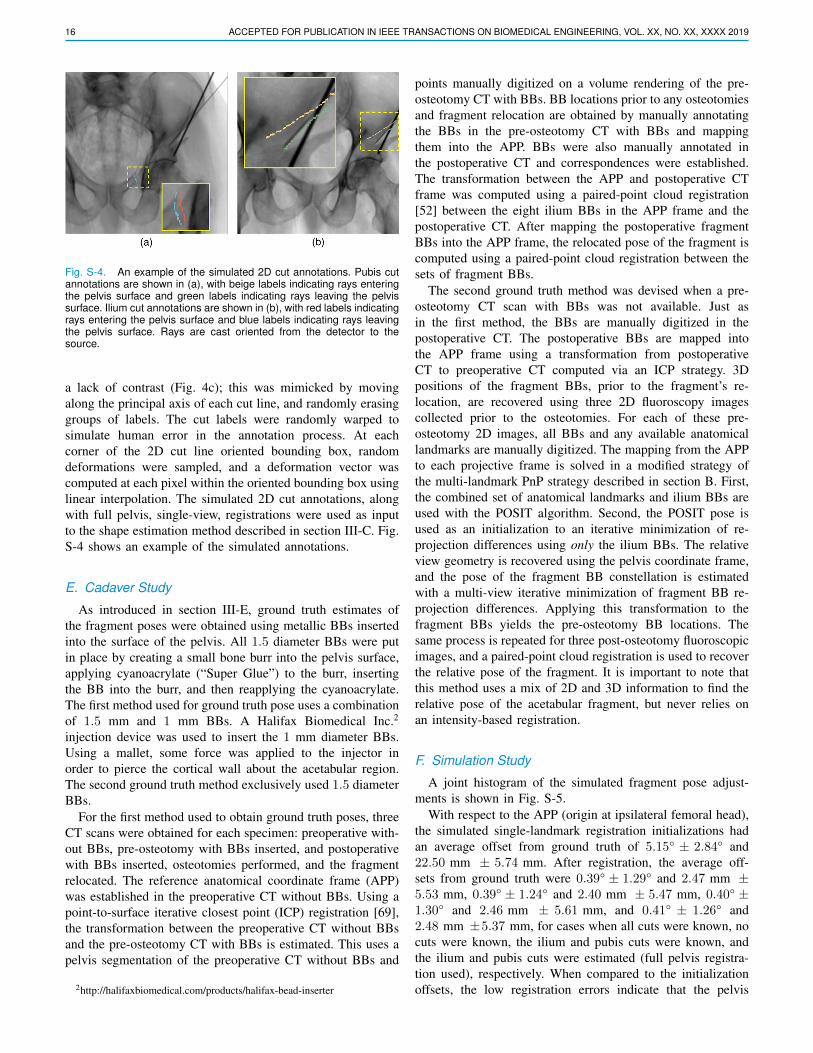
16 ACCEPTED FOR PUBLICATION IN IEEE TRANSACTIONS ON BIOMEDICAL ENGINEERING, VOL. XX, NO. XX, XXXX 2019
Fig. S-4. An example of the simulated 2D cut annotations. Pubis cutannotations are shown in (a), with beige labels indicating rays enteringthe pelvis surface and green labels indicating rays leaving the pelvissurface. Ilium cut annotations are shown in (b), with red labels indicatingrays entering the pelvis surface and blue labels indicating rays leavingthe pelvis surface. Rays are cast oriented from the detector to thesource.
a lack of contrast (Fig. 4c); this was mimicked by movingalong the principal axis of each cut line, and randomly erasinggroups of labels. The cut labels were randomly warped tosimulate human error in the annotation process. At eachcorner of the 2D cut line oriented bounding box, randomdeformations were sampled, and a deformation vector wascomputed at each pixel within the oriented bounding box usinglinear interpolation. The simulated 2D cut annotations, alongwith full pelvis, single-view, registrations were used as inputto the shape estimation method described in section III-C. Fig.S-4 shows an example of the simulated annotations.
E. Cadaver Study
As introduced in section III-E, ground truth estimates ofthe fragment poses were obtained using metallic BBs insertedinto the surface of the pelvis. All 1.5 diameter BBs were putin place by creating a small bone burr into the pelvis surface,applying cyanoacrylate (“Super Glue”) to the burr, insertingthe BB into the burr, and then reapplying the cyanoacrylate.The first method used for ground truth pose uses a combinationof 1.5 mm and 1 mm BBs. A Halifax Biomedical Inc.2
injection device was used to insert the 1 mm diameter BBs.Using a mallet, some force was applied to the injector inorder to pierce the cortical wall about the acetabular region.The second ground truth method exclusively used 1.5 diameterBBs.
For the first method used to obtain ground truth poses, threeCT scans were obtained for each specimen: preoperative with-out BBs, pre-osteotomy with BBs inserted, and postoperativewith BBs inserted, osteotomies performed, and the fragmentrelocated. The reference anatomical coordinate frame (APP)was established in the preoperative CT without BBs. Using apoint-to-surface iterative closest point (ICP) registration [69],the transformation between the preoperative CT without BBsand the pre-osteotomy CT with BBs is estimated. This uses apelvis segmentation of the preoperative CT without BBs and
2http://halifaxbiomedical.com/products/halifax-bead-inserter
points manually digitized on a volume rendering of the pre-osteotomy CT with BBs. BB locations prior to any osteotomiesand fragment relocation are obtained by manually annotatingthe BBs in the pre-osteotomy CT with BBs and mappingthem into the APP. BBs were also manually annotated inthe postoperative CT and correspondences were established.The transformation between the APP and postoperative CTframe was computed using a paired-point cloud registration[52] between the eight ilium BBs in the APP frame and thepostoperative CT. After mapping the postoperative fragmentBBs into the APP frame, the relocated pose of the fragment iscomputed using a paired-point cloud registration between thesets of fragment BBs.
The second ground truth method was devised when a pre-osteotomy CT scan with BBs was not available. Just asin the first method, the BBs are manually digitized in thepostoperative CT. The postoperative BBs are mapped intothe APP frame using a transformation from postoperativeCT to preoperative CT computed via an ICP strategy. 3Dpositions of the fragment BBs, prior to the fragment’s re-location, are recovered using three 2D fluoroscopy imagescollected prior to the osteotomies. For each of these pre-osteotomy 2D images, all BBs and any available anatomicallandmarks are manually digitized. The mapping from the APPto each projective frame is solved in a modified strategy ofthe multi-landmark PnP strategy described in section B. First,the combined set of anatomical landmarks and ilium BBs areused with the POSIT algorithm. Second, the POSIT pose isused as an initialization to an iterative minimization of re-projection differences using only the ilium BBs. The relativeview geometry is recovered using the pelvis coordinate frame,and the pose of the fragment BB constellation is estimatedwith a multi-view iterative minimization of fragment BB re-projection differences. Applying this transformation to thefragment BBs yields the pre-osteotomy BB locations. Thesame process is repeated for three post-osteotomy fluoroscopicimages, and a paired-point cloud registration is used to recoverthe relative pose of the fragment. It is important to note thatthis method uses a mix of 2D and 3D information to find therelative pose of the acetabular fragment, but never relies onan intensity-based registration.
F. Simulation Study
A joint histogram of the simulated fragment pose adjust-ments is shown in Fig. S-5.
With respect to the APP (origin at ipsilateral femoral head),the simulated single-landmark registration initializations hadan average offset from ground truth of 5.15° ± 2.84° and22.50 mm ± 5.74 mm. After registration, the average off-sets from ground truth were 0.39° ± 1.29° and 2.47 mm ±5.53 mm, 0.39° ± 1.24° and 2.40 mm ± 5.47 mm, 0.40° ±1.30° and 2.46 mm ± 5.61 mm, and 0.41° ± 1.26° and2.48 mm ±5.37 mm, for cases when all cuts were known, nocuts were known, the ilium and pubis cuts were known, andthe ilium and pubis cuts were estimated (full pelvis registra-tion used), respectively. When compared to the initializationoffsets, the low registration errors indicate that the pelvis

GRUPP et al.: POSE ESTIMATION OF PERIACETABULAR OSTEOTOMY FRAGMENTS WITH INTRAOPERATIVE X-RAY NAVIGATION 17
Fig. S-5. A 2D histogram of the rotation and translation magnitudes forthe fragment poses sampled as part of the simulation study. Note thatthis is not a uniform distribution matching the parameters in Table S-5due to the rejection sampling via collision detection.
TABLE S-6CADAVER SURGERY GROUND TRUTH VALUES
Surgery Rotation (°) Translation (mm) LCEAP LR IS Total AP LR IS Total#1 Left −4.8 −0.1 +1.1 5.0 −0.5 +2.0 −4.3 4.8 36.7#2 Left +2.4 +13.8 +12.9 18.8 +1.8 −0.6 −2.1 2.8 39.3#2 Right +6.8 +12.3 −14.0 20.2 −1.0 −4.6 −1.0 4.8 42.6#5 Right +6.2 +11.5 −6.0 14.6 −0.3 −1.4 −2.0 2.5 57.1#6 Left −3.1 +17.2 +10.3 20.5 −2.0 −0.2 −3.1 3.7 42.8#6 Right +6.3 +11.6 −1.5 13.3 −1.0 +3.4 +1.9 4.0 41.2Ground truth pose parameters and lateral center edge (LCE) angles ofthe adjusted fragment for each cadaver surgery. LCE angles are measuredin degrees. The transform is with respect to the APP with origin at theipsilateral femoral head. The specimen numbers correspond to Table S-1.
registration is robust against the inherent inaccuracy of thesingle-landmark initialization strategy.
Histograms of the lateral center edge (LCE) angle estimatesare shown in Fig. S-6. An increase in variance is noticeableas mismatch between the fragment shape used for registrationand the actual fragment increases.
G. Cadaver StudyFig. S-7 shows the fluoroscopy used for each cadaver
experiment, along with 3D visualizations of each fragment’sground truth pose. The explicit values of the ground truth posesand LCE angles are listed in Table S-6.
For each case that used single-landmark initialization, man-ually identifying the MOF in each AP view took approxi-mately 2 seconds. In order to analyze the annotation times,multiple landmarks were annotated in all initial views, takingan average time of 14.3 ± 3.3 seconds. The times measuredfor multiple-landmark annotations are listed in Table S-7.
The pipeline components, excluding manual annotations,for each cadaver surgery were re-run 20 times to collectruntime statistics. Single-landmark pelvis pose initialization isa very quick, non-iterative, method which always completedin less than 0.001 seconds. The multiple-landmark pelvis poseinitialization was also very quick, and always completed in
Fig. S-6. Histograms of lateral center edge (LCE) angle errors forthe simulation studies. (a) The actual fragment shape is known andmatches the planned fragment shape, (b) the actual fragment shape isnot known and none of the osteotomies match the planned fragment,(c) the actual fragment is partially known, with the ilium and pubisosteotomies matching the planned fragment, (d) the actual fragment isnot known, but the ilium and pubis osteotomies are estimated from 2Dcut lines.
TABLE S-7CADAVER EXPERIMENT MULTIPLE-LANDMARK ANNOTATION TIMES
Surgery #1 Left #2 Left #2 Right #5 Right #6 Left #6 RightTime (seconds) 8 14 16 17 16 15Time measured to complete the manual annotation of multiple 2D landmarksfor the initial views of each surgery. The specimen numbers correspondto Table S-1. When reporting registration results, the multiple landmarkinitialization strategy was only used for the left side of specimen 1 andright side of specimen 2.
less than 0.1 seconds. Table S-8 shows the times for theintensity-based registrations, manual cut annotations, fragmentshape estimations, and multiple-view fragment registrations.The orbital view registration measurements include time tocompute the 181 DRRs and similarity scores required forinitialization. Summing the mean execution times computedfor the individual steps of the cadaver study, using single-landmark initialization, and the case of intraoperative fragmentestimation, yields an expected runtime of 78.5 seconds. Whenmanual annotation is excluded that time is 25.3 seconds. Thistiming analysis was conducted using a single NVIDIA TeslaP100 (PCIe) GPU and access to seven cores of an Intel XeonE5-2680 v4 CPU.
A breakdown of errors across each surgery, each fragment,each pose dimension, and LCE angles is shown in Table S-9. Visualizations of the rotation, translation, and LCE angledistributions for all surgeries are shown by the violin plots inFigures S-8, S-9, and S-10, respectively.

18 ACCEPTED FOR PUBLICATION IN IEEE TRANSACTIONS ON BIOMEDICAL ENGINEERING, VOL. XX, NO. XX, XXXX 2019
Fig. S-7. Intraoperative fluoroscopy (left) used in the cadaver studies for pose estimation of the acetabular fragment, along with 3D visualizationsof the fragment’s pose (right). Manually annotated landmarks used for registration initialization are overlaid as yellow circles in the approximateAP views shown in the left-most fluoroscopic images. Note the pelvic tilt away from a standard AP orientation for the two cases that require morethan one landmark for initialization. Registration initialization is automatically obtained for the center and right fluoroscopic views which are pureorbital rotations starting from the AP view. The second row, from top, is the specimen shown in Figures 1, 3, 4, and 5. Starting from the top row, thespecimen numbers corresponding to Table S-1 are 1, 2, 2, 5, 6, and 6.

GRUPP et al.: POSE ESTIMATION OF PERIACETABULAR OSTEOTOMY FRAGMENTS WITH INTRAOPERATIVE X-RAY NAVIGATION 19
TABLE S-8CADAVER EXPERIMENT TIMES FOR INTENSITY-BASED
REGISTRATIONS, CUT LINE ANNOTATION, AND FRAGMENT SHAPE
ESTIMATIONS
Surgery Time (seconds)InitialViewRegi.
OrbitalViewRegis.
Cut LineAnnotation
Frag.Shape Est.
3-ViewFrag.Regi.
#1 Left 4.5± 0.2 1.5± 0.1 43 0.7± 0.1 15.6±0.4#2 Left 4.4± 0.1 1.6± 0.1 47 0.9± 0.3 16.3±0.6#2 Right 3.7± 0.2 1.6± 0.1 38 0.9± 0.0 17.2±0.6#5 Right 5.3± 0.3 2.2± 0.1 70 1.2± 0.1 15.8±0.5#6 Left 4.6± 0.1 1.6± 0.1 39 1.0± 0.0 16.6±0.5#6 Right 4.5± 0.3 1.7± 0.1 70 1.0± 0.2 16.7±0.6All 4.5± 0.5 1.7± 0.3 51.2±14.9 1.0± 0.2 16.4±0.8Means and standard deviations of runtimes for individual components ofthe intensity-based registration pipeline for each cadaver surgery. Manualcut line annotation was only performed once per surgery. For the fragmentestimation cases with standard deviation of zero, the actual statistic was< 0.1. The specimen numbers correspond to Table S-1.
Fig. S-8. Violin plot of the rotation errors associated with the cadaverexperiments. Analogous to Table III, the errors are organized by thetype of fragment shape used for pose estimation, the total rotationerror magnitudes, and the decompositions of the errors about eachanatomical axis. For each entry, a scatter plot of the errors is shownby the shaded dots, enclosed by a kernel density function. The whitedot indicates the median, and the vertical bar indicates the [25, 75]percentiles.
Fig. S-9. Violin plot of the translation errors associated with the cadaverexperiments, organized in the same manner as Fig. S-8.
Fig. S-10. Violin plot of the lateral center edge (LCE) angle errorsassociated with the cadaver experiments. The errors are organized bythe type of fragment shape used during registration.

20 ACCEPTED FOR PUBLICATION IN IEEE TRANSACTIONS ON BIOMEDICAL ENGINEERING, VOL. XX, NO. XX, XXXX 2019
TABLE S-9INDIVIDUAL CADAVER SURGERY FRAGMENT POSE AND LATERAL CENTER EDGE ANGLE ERRORS
Surgery Frag. Shape Rotation (°) Translation (mm) LCE (°)AP LR IS Total AP LR IS Total
#1 LeftManual Seg. 0.59 2.79 0.97 3.01 1.58 1.05 3.08 3.62 1.35Planned 0.56±0.61 3.52±1.59 2.17±2.14 4.73±1.47 2.01±2.47 1.45±1.20 2.73±1.09 4.21±2.07 1.55±0.79Estimated 0.29±0.16 3.71±0.32 1.14±0.22 3.90±0.33 0.75±0.43 1.12±0.11 2.86±0.33 3.19±0.38 1.30±0.16
#2 LeftManual Seg. 0.64 2.82 0.74 2.99 1.27 2.50 1.37 3.12 0.50Planned 1.66±1.30 2.40±2.14 1.65±0.84 3.55±2.30 1.01±0.49 2.43±0.18 0.63±0.45 2.77±0.19 1.93±1.40Estimated 1.39±0.44 1.84±1.13 1.50±0.71 2.93±0.90 0.64±0.45 2.64±0.23 0.36±0.28 2.79±0.26 1.80±0.59
#2 RightManual Seg. 0.50 0.53 0.75 1.04 1.82 0.60 0.85 2.09 0.47Planned 1.37±1.16 2.25±1.79 2.13±1.81 3.70±2.29 1.71±1.54 0.27±0.18 0.42±0.36 1.84±1.52 1.17±0.88Estimated 1.25±0.61 1.32±1.47 1.09±0.78 2.30±1.48 1.26±1.25 0.28±0.25 0.35±0.27 1.44±1.16 1.14±0.55
#5 RightManual Seg. 0.07 1.45 1.65 2.20 0.44 0.26 0.14 0.53 1.52Planned 0.46±0.43 2.55±1.74 1.19±0.84 2.96±1.80 0.58±0.46 0.24±0.19 0.64±0.45 0.99±0.51 1.56±1.26Estimated 0.31±0.23 2.47±1.47 1.12±0.58 2.80±1.46 0.61±0.42 0.17±0.13 0.93±0.19 1.18±0.31 1.70±1.12
#6 LeftManual Seg. 0.44 1.07 1.61 1.98 0.83 1.13 0.72 1.57 1.69Planned 2.30±1.11 2.42±1.29 3.20±0.79 4.84±0.98 1.92±0.82 1.20±0.13 1.23±0.36 2.66±0.59 3.70±1.35Estimated 2.15±0.64 3.28±0.83 3.74±0.98 5.51±0.68 1.82±0.85 1.19±0.17 1.14±0.26 2.54±0.62 3.87±0.89
#6 RightManual Seg. 0.80 1.88 0.39 2.08 1.36 0.64 1.55 2.16 0.96Planned 0.71±0.28 2.36±1.55 1.00±0.65 2.83±1.37 1.67±1.01 0.87±0.23 1.31±0.66 2.40±0.98 0.86±0.40Estimated 0.50±0.27 3.03±1.17 0.72±0.53 3.26±0.98 0.77±0.55 1.14±0.33 1.21±0.51 1.95±0.45 1.02±0.37
Summary of the means and standard deviations of the fragment pose and lateral center edge angle (LCE) errors for each cadaver surgery. Specimennumbers correspond to those in Table S-1. The organization presented here is analogous to Table III.