position control of robot arm using genetic algorithm
TRANSCRIPT

Youns: Position Control Of Robot Arm Using Genetic Algorithm Based PID Controller
91
Position Control Of Robot Arm Using Genetic Algorithm Based PID Controller
Majed D. Youns
1 , Salih M. Attya
2 , Abdulla I. Abdulla
3
College of Electronics Engineering / University of Mosul /Mosul, Iraq
[email protected],[email protected]
3
Abstract
It is known that PID controller is used in every facet of industrial automation. The application
of PID controller span from small industry to high technology industry. The aim of this paper
is to design a position controller of a robot arm by selection of a PID parameters using
genetic algorithm. The model of a robot arm is considered a third order system. And this
paper compares two kinds of tuning methods of parameter for PID controller. One is the
controller design by the genetic algorithm, second is the controller design by the Ziegler and
Nichols method. It was found that the proposed PID parameters adjustment by the genetic
algorithm is better than the Ziegler & Nichols’ method. The proposed method could be
applied to the higher order system also.
Keywords: Robot arm, Genetic algorithm(GA), PID controller, Ziegler-Nichols (ZN)
Method.
التفاضلي بالاستناد -التكاملي -المسيطر التناسبي باستخدام أليذراع ل موقعالعلى تحكمال
. ةجينيال يةخوارزمإلى ال
ر يونسد.ماجد ضرا1
صالح محمود عطية ، 2
عبد الله إبراهيم عبدالله ، 3
مدرس مساعد ، مدرس مساعد ، مدرس
كلية هندسة الالكترونيات /جامعة الموصل/ الموصل /العراق
ةصالخلا
وكما يتم كل جانب من جوانب الأتمتة الصناعية يستخدم في التفاضلي -التكاملي -ر التناسبي المسيطمن المعروف أن
لي.أالمسيطر للسيطرة على الموقع الزاوي لذراع الهدف من هذا البحث هو تصميمإن . في مختلف تقنيات الصناعة هتطبيق
من ظامن تم اعتباره الآليذراع الموديل الرياضي لل جينية. بالاستناد على تقنية الخوارزمية اليتم اختيار ثوابت هذا المسيطر
ألأول باستخدام الخوارزمية الأسلوب .تنغيم ثوابت المسيطرأساليب نوعين من بين . يقارن هذا البحثةالثالث الدرجة
الأول أفضل من الأسلوب من خلال مقارنة النتائج تبين إن الأسلوب نكلس. –الجينية أما الثاني تم باستخدام طريقة زيكلر
. أعلىعلى نظام ذو درجة الأول الأسلوبكما يمكن تطبيق الثاني .
نكلس -التفاضلي، طريقة زيكلر-التكاملي-الذراع الآلي، الخوارزمية الجينية،المسيطر التناسبي الكلمات الدالة:
Received: 6 – 6 - 2012 Accepted: 22 – 4 - 2013
Al-Rafidain Engineering Vol.21 No. 6 December 2013
02
1-Introduction:
In general, the arm of a robot has a number of joints .The current approach to the design of
control system for robot joints is to treat each joint of the arm as a simple joint
servomechanism, ignoring the effect of the movements of all other joints. In industrial robots,
hydraulic or pneumatic actuators may be used rather than dc servomotors. Due to it's excellent
speed and position control characteristic ,the dc servomotors has been widely used in
industry ,therefore the actuator is assumed to be an armature-control dc motor . In addition it
is assumed that the robot arm is connected to the motor through gears. Proportional-Integral-
Derivative (PID) controllers have been widely used for speed and position control of robot
arm. This paper endeavors to design a system using Genetic Algorithm (GA). Genetic
Algorithm (GA) is a stochastic algorithm based on principles of natural selection and
genetics. Genetic Algorithms (GAs) are a stochastic global search method that mimics the
process of natural evolution. Using genetic algorithms to perform the tuning of the controller
will result in the optimum controller being evaluated for the system every time. The objective
of this paper is to show that by using the GA method of tuning a system , an optimization can
be achieved. This can be seen by comparing the result of the GA optimized system against the
classically tuned system.[6]
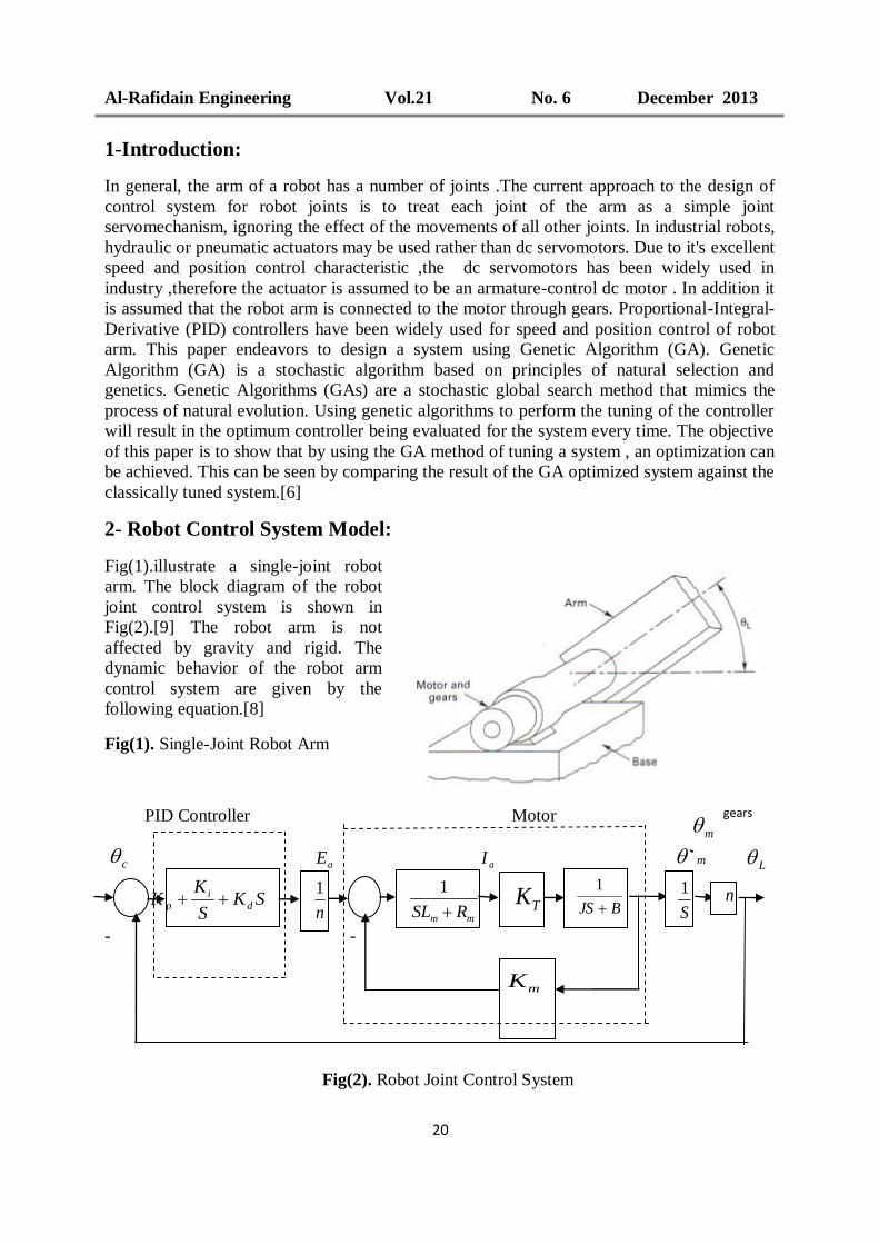
2- Robot Control System Model:
Fig(1).illustrate a single-joint robot
arm. The block diagram of the robot
joint control system is shown in
Fig(2).[9] The robot arm is not
affected by gravity and rigid. The
dynamic behavior of the robot arm
control system are given by the
following equation.[8]
Fig(1). Single-Joint Robot Arm
PID Controller Motor
aE
aI
m
- -
Fig(2). Robot Joint Control System
SKS
KK d
i
p
mm RSL
1
BJS
1
n
mK
TK
S
1
gears
L
c
n
1
m

Youns: Position Control Of Robot Arm Using Genetic Algorithm Based PID Controller
09
)()(
)()( tedt
tdiLtiRte m
a
mama - ------------------ (1)
dt
tdKte m
mm
)()(
------------------ (2)
)(tiKT aTm ------------------ (3)
dt
tdB
dt
tdJT mm
m
)()(2
2 ------------------ (4)
JlnJJ m
2 ------------------ (5)
BlnBB m
2 ------------------ (6)
mL n ------------------ (7)
After simplification and taking the ratio of )(
)(sE
s
a
L we will get the transfer function as
below.
SBRKKSBLJRSJL
nK
sE
s
mmTmmm
T
a
L
)()()(
)(23
------------------ (8)
Where.
mR armature- winding resistance in ohm. mL armature - winding inductance in Henry. ai armature - winding current in ampere. ae armature voltage in volt . me back emf voltage in volt. mK back emf constant in volt / (rad/sec) mT torque developed by the motor in N.m TK motor torque constant in N.m/A
J moment of inertia of motor and robot arm in kg. 2m /rad. B viscous - friction coefficient of motor and robot arm in N.m/rad /sec. m angular displacement of the motor shaft in rad. L angular displacement of the robot arm in rad. c angular displacement of the reference input in rad. n gear ratio
2
1
NN
The robot arm control system under study has the following parameters.
mR 21 , mL 2 , TK 38 N.m/A , J 2 kg.m2 /rad , B 1 N.m/rad/sec , mK 0.5
V/(rad/sec) and n20
1 .
The block diagram of the servo control system for one of the joint of a robot is shown in
Fig(3).[8]

Al-Rafidain Engineering Vol.21 No. 6 December 2013
00
PID Controller
c L
-
Fig.(3). Joint Control System For A Robot Arm .
3- Ziegler -Nichols Rule For Tuning PID Controller:
The control system performs poor in characteristics and even it becomes unstable, if improper
values of the controller tuning constants are used. So it becomes necessary to tune the
controller parameters to achieve good control performance with the proper choice of tuning
constants. Controller tuning involves the selection of the values of kp, Ki and Kd.By setting Ki
=0 and Kd=0 ,we obtain the closed- loop transfer function. The value of kp that makes the
system marginally stable so that sustained oscillation occurs can be obtained by use of Routh's
stability criterion .By examining the coefficients of the first column of the Routh table, we
find that sustained oscillation will occur if Kp = 11.57 .Thus the critical gain Kcr=11.57 .To
find the frequency of oscillation (w),we substitute S=jw in the characteristics equation .From
which we find w= 3.16 rad/sec. Hence ,the period of sustained oscillation (pcr) is 2π/w= 2
sec .Referring to table 1 ,we determine Kp , Ki and Kd as follows[1]
Kp=0.6 Kcr= 6.94 , Ki=1.2 Kcr/Pcr=6.94 and Kd=0.075 Kcr*Pcr =1.73 .
Table 1 : Ziegler-Nichols Tuning Rule
Type of controller Kp Ki Kd
P 0.5Kcr 0 0
PI o.45Kcr 0.54 Kcr/Pcr 0
PID 0.6Kcr 1.2 Kcr/Pcr 0.075 Kcr*Pcr
The unit step response of the closed -loop system with PID controller can be obtained easily
with MATLAB. The maximum overshoot is approximately 63%. The amount of maximum
overshoot is excessive. It can be reduced by fine tuning the controller parameter. Such fine
tuning can be made on the computer .The important thing to note here is that the Ziegler-
Nichols tuning rule has provided a starting point for fine tuning .It is approximately twice the
value suggested by the Ziegler-Nichols tuning rule.[1]
Kp= 15.26 , Ki= 6.94 and Kd= 8.39 .
The transfer function of the PID controller is
SKS
KK d
i
p SSS 40444
3823
+
Youns: Position Control Of Robot Arm Using Genetic Algorithm Based PID Controller
02
S
KSKSKsG
ipd
c
2
)(
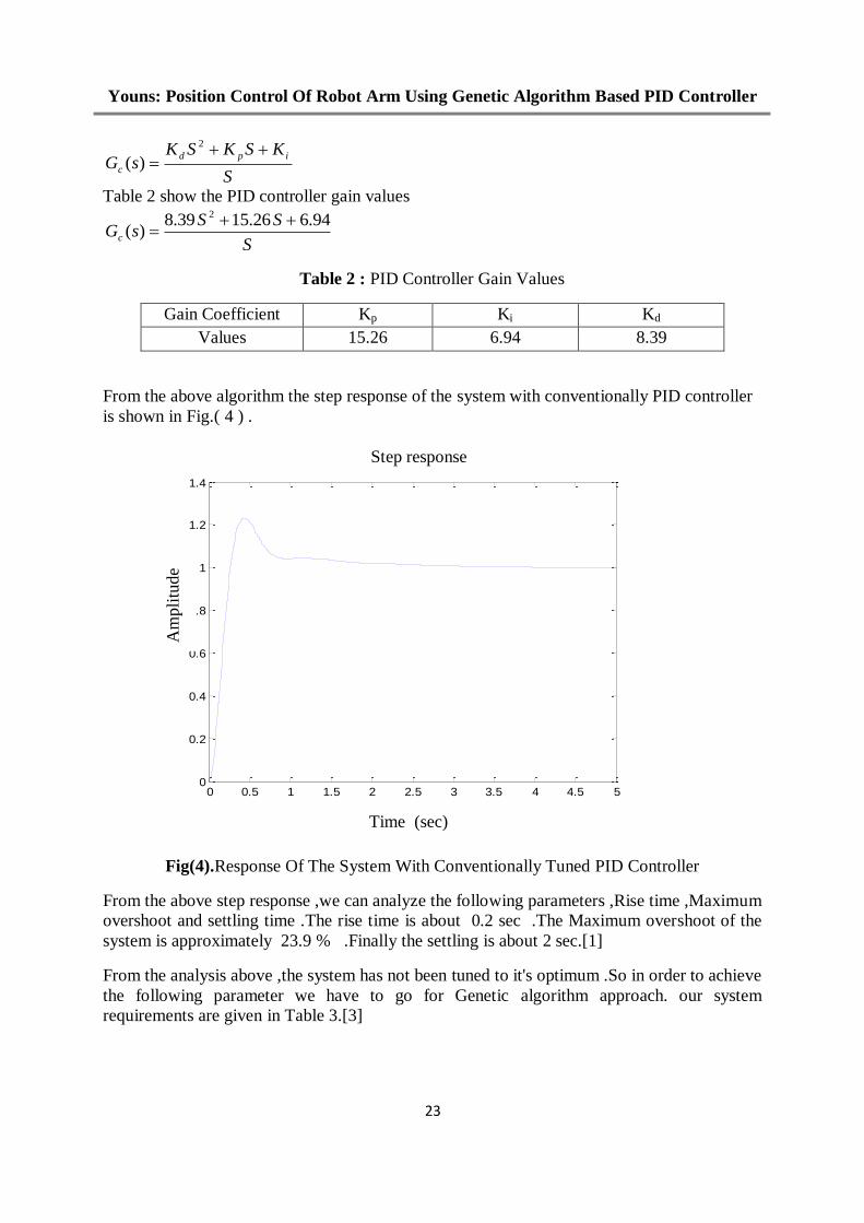
Table 2 show the PID controller gain values
S
SSsGc
94.626.1539.8)(
2
Table 2 : PID Controller Gain Values
Gain Coefficient Kp Ki Kd
Values 15.26 6.94 8.39
From the above algorithm the step response of the system with conventionally PID controller
is shown in Fig.( 4 ) .
Fig(4).Response Of The System With Conventionally Tuned PID Controller
From the above step response ,we can analyze the following parameters ,Rise time ,Maximum
overshoot and settling time .The rise time is about 0.2 sec .The Maximum overshoot of the
system is approximately 23.9 % .Finally the settling is about 2 sec.[1]
From the analysis above ,the system has not been tuned to it's optimum .So in order to achieve
the following parameter we have to go for Genetic algorithm approach. our system
requirements are given in Table 3.[3]
0 0.5 1 1.5 2 2.5 3 3.5 4 4.5 50
0.2
0.4
0.6
0.8
1
1.2
1.4
Time (sec)
Am
pli
tude
Step response

Al-Rafidain Engineering Vol.21 No. 6 December 2013
02
Table 3 : System Requirements
System
Specification
Max Over Shoot Rise Time (Sec) Settling Time (Sec)
< 15 % < 0.4 < 0.8
4-Tuning of PID controller using genetic algorithm approach :
GA is a stochastic global adaptive search optimization technique based on the mechanisms of
natural selection. Recently, GA
has been recognized as an
effective and efficient technique
to solve optimization problem.
Compared with other optimization
techniques. GA starts with an
initial population containing a
number of chromosomes where
each one represents a solution of
the problem which performance is
evaluated by a fitness function.
Basically, GA consists of three
main stages: Selection, Crossover
and Mutation. The application of
these three basic operations
allows the creation of new
individuals which may be better
than their parents. This algorithm
is repeated for many generations
and finally stops when reaching
individuals that represent the
optimum solution to the problem.
The GA architecture is shown in
Fig.5.[6]
5-Genetic Algorithm For
PID Tuning The implementation of the tuning procedure through genetic algorithms starts with the
definition of the chromosome representation. As illustrated in Fig.6 ,the chromosome is
formed by three values that correspond to the three gains to be adjusted in order to achieve a
satisfactory behavior. The gains Kp , Ki and Kd are real numbers and characterize the
individual to be evaluated.[5]
Fig.6 Chromosome Definition
Kp Ki Kd
Start
Inputs No. Of Chromosome=80
Initial Value
Random=[ Kp Ki Kd]
Evaluate Fitness function value For
Each Chromosome
Is Max.
Number of
generation
is achieved
Index reached
Perform Selection, Crossover
And Mutation Process
Stop
Gen=Gen+1
Best chromosome =[Kp Ki Kd]
No
Yes Fig.5. Simulation flow chart for the computation of
GA-PID controller parameters
Youns: Position Control Of Robot Arm Using Genetic Algorithm Based PID Controller
02
The objective function is the calculation of its associated fitness. The fitness function is the
measure of the quality of chromosome and can be defined as.
5-1 First Fitness Function (minimize the settling time, rise time and the overshoot):
Minimize J
Where,
N
i
ieN
J1
1
N=3 and
ei={tsga/tszn, trga/trzn, Mpga/Mpzn} , where,
tsga is the settling time, trga is the rising time and Mpga is the maximum over shoot
5-2 Second Fitness Function (minimize the settling Time only ):
Minimize J
Where,
J = tsga
tsga is the settling time
5-3 Third Fitness Function (based on model reference approach): Minimize J
Where,
tMyyJ axsm /)( 2
ys system response.
ym model response.
Max t = 500 Sample
t/(Nm-1) for 0 ≤ t < Nm
1 for t ≥ Nm
Nm= 21, 26, 31 and 36 Sample
Note .Each 100 sample equal 1sec (sampling time =0.01sec).
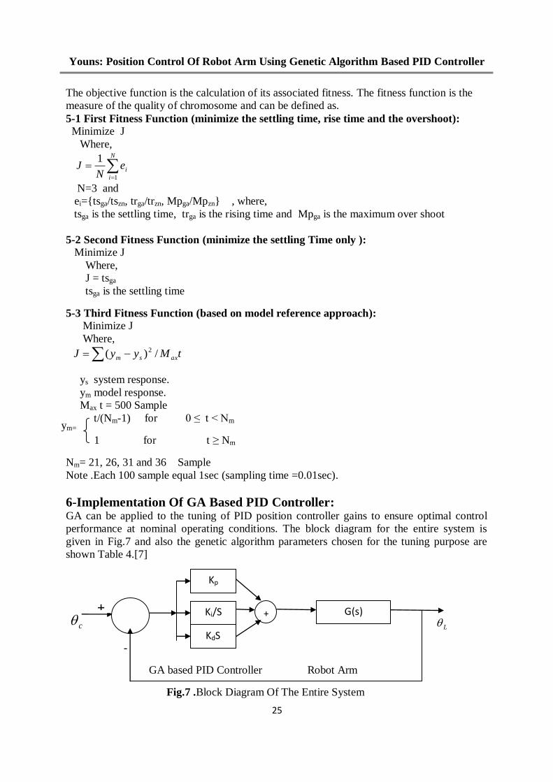
6-Implementation Of GA Based PID Controller: GA can be applied to the tuning of PID position controller gains to ensure optimal control
performance at nominal operating conditions. The block diagram for the entire system is
given in Fig.7 and also the genetic algorithm parameters chosen for the tuning purpose are
shown Table 4.[7]
c L
-
GA based PID Controller Robot Arm
Fig.7 .Block Diagram Of The Entire System
ym=
+ G(s)
Kp
Ki/S
KdS
+
Al-Rafidain Engineering Vol.21 No. 6 December 2013
02
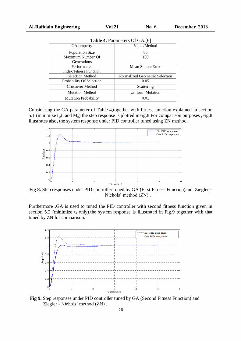
Table 4. Parameters Of GA.[6] GA property Value/Method
Population Size
Maximum Number Of
Generations
80
100
Performance
Index/Fitness Function
Mean Square Error
Selection Method Normalized Geometric Selection
Probability Of Selection 0.05
Crossover Method Scattering
Mutation Method Uniform Mutation
Mutation Probability 0.01
Considering the GA parameter of Table 4,together with fitness function explained in section
5.1 (minimize ts,tr and Mp) the step response is plotted inFig.8.For comparison purposes ,Fig.8
illustrates also, the system response under PID controller tuned using ZN method.
Fig 8. Step responses under PID controller tuned by GA (First Fitness Function)and Ziegler -
Nichols’ method (ZN) .
Furthermore ,GA is used to tuned the PID controller with second fitness function given in
section 5.2 (minimize ts only).the system response is illustrated in Fig.9 together with that
tuned by ZN for comparison.
Fig 9. Step responses under PID controller tuned by GA (Second Fitness Function) and
Ziegler - Nichols’ method (ZN) .
0 1 2 3 4 5 60
0.2
0.4
0.6
0.8
1
1.2
1.4
Time(Sec)
Am
plitu
de
ZN PID response
GA PID response
Am
pli
tude
Time (sec)

Youns: Position Control Of Robot Arm Using Genetic Algorithm Based PID Controller
02
Finally, the PID controller tuned by GA according to the third fitness function (section 5-3)is
illustrated in Fig.10.
Fig.10 GA-tuned PID controller based on model- reference approach.
The following prescribed model references are used.
sec2.058344
58321
sm tfor
ssG
sec25.050344
50322
sm tfor
ssG
sec3.044444
44423
sm tfor
ssG
sec35.039744
39724
sm tfor
ssG
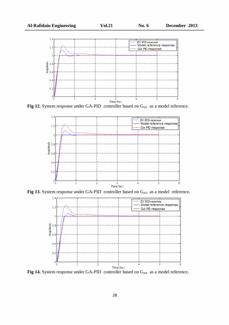
Figures 11 to 14 ,illustrate the GA-PID controller tuned according to 3rd
fitness function (in a
model reference context ) using Gm1, Gm2, Gm3 and Gm4 as a model reference. Moreover ,the
ZN tuned PID response is also plotted for comparison.
Fig 11. System response under GA-PID controller based on Gm1 as a model reference.
Step response
PID plant
GA
Model reference
-
-
+ ym
ys
em
Kp Ki kd
cym
Al-Rafidain Engineering Vol.21 No. 6 December 2013
02
Fig 12. System response under GA-PID controller based on Gm2 as a model reference.
Fig 13. System response under GA-PID controller based on Gm3 as a model reference.
Fig 14. System response under GA-PID controller based on Gm4 as a model reference.
Time (sec)
Youns: Position Control Of Robot Arm Using Genetic Algorithm Based PID Controller
01
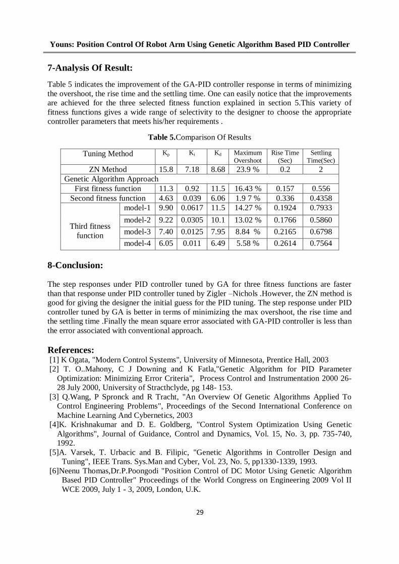
7-Analysis Of Result:
Table 5 indicates the improvement of the GA-PID controller response in terms of minimizing
the overshoot, the rise time and the settling time. One can easily notice that the improvements
are achieved for the three selected fitness function explained in section 5.This variety of
fitness functions gives a wide range of selectivity to the designer to choose the appropriate
controller parameters that meets his/her requirements .
Table 5.Comparison Of Results
Tuning Method Kp Ki Kd Maximum
Overshoot
Rise Time
(Sec)
Settling
Time(Sec)
ZN Method 15.8 7.18 8.68 23.9 % 0.2 2
Genetic Algorithm Approach
First fitness function 11.3 0.92 11.5 16.43 % 0.157 0.556
Second fitness function 4.63 0.039 6.06 1.9 7 % 0.336 0.4358
Third fitness
function
model-1 9.90 0.0617 11.5 14.27 % 0.1924 0.7933
model-2 9.22 0.0305 10.1 13.02 % 0.1766 0.5860
model-3 7.40 0.0125 7.95 8.84 % 0.2165 0.6798
model-4 6.05 0.011 6.49 5.58 % 0.2614 0.7564
8-Conclusion:
The step responses under PID controller tuned by GA for three fitness functions are faster
than that response under PID controller tuned by Zigler –Nichols .However, the ZN method is
good for giving the designer the initial guess for the PID tuning. The step response under PID
controller tuned by GA is better in terms of minimizing the max overshoot, the rise time and
the settling time .Finally the mean square error associated with GA-PID controller is less than
the error associated with conventional approach.
References: [1] K Ogata, "Modern Control Systems", University of Minnesota, Prentice Hall, 2003
[2] T. O..Mahony, C J Downing and K Fatla,"Genetic Algorithm for PID Parameter
Optimization: Minimizing Error Criteria", Process Control and Instrumentation 2000 26-
28 July 2000, University of Stracthclyde, pg 148- 153.
[3] Q.Wang, P Spronck and R Tracht, "An Overview Of Genetic Algorithms Applied To
Control Engineering Problems", Proceedings of the Second International Conference on
Machine Learning And Cybernetics, 2003
[4]K. Krishnakumar and D. E. Goldberg, "Control System Optimization Using Genetic
Algorithms", Journal of Guidance, Control and Dynamics, Vol. 15, No. 3, pp. 735-740,
1992.
[5]A. Varsek, T. Urbacic and B. Filipic, "Genetic Algorithms in Controller Design and
Tuning", IEEE Trans. Sys.Man and Cyber, Vol. 23, No. 5, pp1330-1339, 1993.
[6]Neenu Thomas,Dr.P.Poongodi "Position Control of DC Motor Using Genetic Algorithm
Based PID Controller" Proceedings of the World Congress on Engineering 2009 Vol II
WCE 2009, July 1 - 3, 2009, London, U.K.

Al-Rafidain Engineering Vol.21 No. 6 December 2013
22
[7] Naeem, W., Sutton, R. Chudley. J, Dalgleish, F.R. and Tetlow, S., . "An Online Genetic
Algorithm Based Model Predictive Control Autopilot Design With Experimental
Verification". International Journal Of Control, Vol 78, No. 14, pg 1076 . 1090,
September 2005
[8] L.phillips and D.Harbar, "Feedback Controller System ",3rd
edition , Prentice Hall, 1996
[9] Chun Htoo Aung, Khin Thandar Lwin, and Yin Mon Myint," Modeling Motion Control
System for Motorized Robot Arm using MATLAB" World Academy of Science,
Engineering and Technology 42, 2008
The work was carried out at the college of Engineering. University of Mosul