positioning of transparent targets using defocusing … · we report a positioning method for...
TRANSCRIPT

Article submitted to: High Power Laser Science and Engineering, 2018 April 30, 2018
Positioning of Transparent Targets Using DefocusingMethod in a Laser Proton Accelerator
Yinren Shou1, Dahui Wang1,2, Pengjie Wang1, Jianbo Liu1, Zhengxuan Cao1, Zhusong Mei1, Yixing Geng1,Jungao Zhu1, Qing Liao1, Yanying Zhao1, Chen Lin1, Haiyang Lu1, Wenjun Ma1,3, and Xueqing Yan1,3,4
1State Key Laboratory of Nuclear Physics and Technology, and Key Laboratory of HEDP of the Ministry ofEducation, CAPT, Peking University, Beijing 100871, China2State Key Laboratory of Laser Interaction with Matter, Northwest Institute of Nuclear Technology, P. O.Box 69-26, Xi’an 710024, China3Shenzhen Research Institute of Peking University, Shenzhen 518055, China4Collaborative Innovation Center of Extreme Optics, Shanxi University, Taiyuan, Shanxi 030006, China
AbstractWe report a positioning method for transparent targets with an accuracy of 2µm for a compact laser proton accelerator.The positioning system consists of two light-emitting diodes (LED), a long working distance objective and two chargecoupled devices (CCD) for illumination, imaging and detection, respectively. We developed a defocusing method makingtransparent targets visible as phase objects and applied it to our system. Precise positioning of transparent targets can berealized by means of minimizing the image contrast of the phase objects. Fast positioning based on the relationshipbetween the radius of spherical aberration ring and defocusing distance is also realized. Laser proton accelerationexperiments have been performed to demonstrate the reliability of this positioning system.
Keywords: relativistic laser; Transparent targets positioning system; laser-driven ion source
1. Introduction
Highly energetic ions can be generated when a relativisticlaser pulse (intensity I exceeding 2.14× 10¹⁸ W/cm2 forwavelength λ = 800 nm) is focused on a solid target. [1–3]
Compact proton accelerators based on laser solid interactionhave three orders of magnitude higher acceleration gradientin comparison to conventional accelerators. [4] The obtainedproton beams with the characters of ultrashort duration, ex-treme brightness and small emittance are suitable for a seriesof potential applications, for instance, production of warmdense matter [5], injectors for conventional accelerators [6]
and tumor therapy [7].The accuracy of target positioning can directly influence
the intensity of laser pulse irradiated on the target, whichis a key point to improve the cut-off energy of laser-drivenprotons. The well-studied proton acceleration mechanismnamed target normal sheath acceleration [8] (TNSA) pre-dicted a relationship between the maximum proton energyand laser intensity as Emax ∝ I1/2 theoretically. [9] Scalinglaws investigated in a huge number of experiments world-
Correspondence to: W. Ma and X. Yan, State Key Laboratory of NuclearPhysics and Technology, Peking University, Beijing 100871, China. Email:[email protected], [email protected]
wide indicated Emax ∝ I0.7−1 for short duration pulses(30 ∼ 100 fs) and Emax ∝ I0.5 for long duration pulses(0.3 ∼ 1.0 ps). [10,11] Another important acceleration mecha-nism promising for the generation of quasi-monoenergeticprotons named radiation pressure acceleration (RPA) alsopredicted a scaling law as Emax ∝ I . [12,13] In order toincrease the intensity, and consequently, to improve themaximum energy of the proton beams, small f-number off
axis parabolic (OAP) mirrors are widely used to tightly focusthe laser beam to micrometer-scale spot. However, a tightlyfocused pulse will lead to an extreme short Rayleigh length,which requires precise target positioning. A number ofexperiments have been performed to investigate the depen-dency of the proton energy on the position of the targetswith respect to the laser focus spot. [14–16] For instance, it’sreported that 8µm difference on shooting position can resultin 30% difference on the maximum proton energy and nearlyone order of magnitude larger proton flux when an f/2 OAPis used. [17]
In order to precisely position the target, several methodshave been proposed and utilized in laser-driven proton ac-celeration experiments. A widely used indirect detectionmethod is transverse shadowgraphy imaging, which is suit-
1
arX
iv:1
804.
1043
3v1
[ph
ysic
s.ap
p-ph
] 2
7 A
pr 2
018
2 Y. Shou et al.
able for few-micrometer-thick targets by imaging the thinside of the target using a CCD camera. [18] Retro-focus sys-tem has also been applied to target positioning. This schemeinjects a green pulse through the back of a dielectric infra-red mirror and then images the back-scattered light fromthe target. [19] Another indirect detection method employingmulti-wavelength interferometer can realize an accuracy of10µm with the use of a three-wavelength interferometerbased on a Mach-Zehnder design. The target is placedat one arm of the interferometer as a reflecting mirror torecord depth changes. [20] However, these indirect detectionschemes are not very reliable due to the absence of targetsurface imaging. Directly imaging of the target surfacecan be realized by using Questar telephoto microscope [16]
or a long work distance objective. [17] Recently, Gao et al.improved the objective imaging method with a confocaldistance sensor and demonstrated the possibility of aligningnanometer targets with 1 Hz repetition rate. [21]
2. Target positioning system
Nowadays, transparent targets such as plastic foils [22], DLCtargets [23], liquid crystal films [24] and Si3N4 targets [25], arewidely applied in laser-driven proton accelerations. Pro-ton beams with cut-off energy higher than 80MeV havebeen obtained from plastic targets. [26,27] However, precisepositioning of such transparent targets by directly imagingmethod normally is difficult. One reported solution is puttingvisible objects, for example, tiny dots or opaque coatingpatterns, on the surface of transparent targets [24]. Butit makes the target production process more complicated.In the present work, we report a positioning system forboth opaque and transparent targets with an accuracy of2µm. Defocusing method [28–30] is applied to our positioningsystem to make transparent targets visible as phase objects.Precise positioning of transparent targets can be realized byminimizing the image contrast of the phase objects. Fastpositioning by surveying the radius of spherical aberrationring of the phase objects is also realized. The reliabilityof this positioning system has been verified by performinglaser proton acceleration experiments with varied defocusing
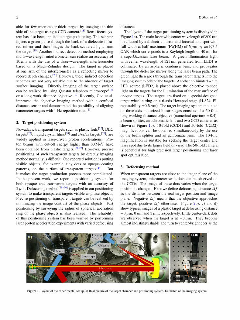
distances.The layout of the target positioning system is displayed in
Figure 1a). The main laser with center wavelength of 800 nmis reflected by a dielectric mirror and focused to a spot withfull width at half maximum (FWHM) of 5µm by an F/3.5OAP, which corresponds to a Rayleigh length of 40µm fora superGaussian laser beam. A green illumination lightwith center wavelength of 525 nm generated from LED1 iscollimated by an aspheric condenser lens, and propagatesthrough the dielectric mirror along the laser beam path. Thegreen light then goes through the transparent targets into theimaging system behind the targets. Another collimated whiteLED source (LED2) is placed above the objective to shedlight on the targets for the illumination of the rear surface ofopaque targets. The targets are fixed on a special-designedtarget wheel sitting on a 6-axis Hexapod stage (H-824, PI,repeatability ±0.5µm). The target imaging system mountedon three-axis motorized linear stages consists of a 50-foldlong working distance objective (numerical aperture = 0.4),a beam splitter, an achromatic lens and two CCD cameras asshown in Figure 1b). 10-fold (CCD1) and 50-fold (CCD2)magnifications can be obtained simultaneously by the useof the beam splitter and an achromatic lens. The 10-foldmagnification is suitable for seeking the target center andlaser spot due to its larger field of view. The 50-fold camerais beneficial for high precision target positioning and laserspot optimization.
3. Defocusing method
When transparent targets are close to the image plane of theimaging system, micrometer-scale dots can be observed onthe CCDs. The image of these dots varies when the targetposition is changed. Here we define defocusing distance ∆fas the distance between the real target position and imageplane. Negative ∆f means that the objective approachesthe target, positive ∆f otherwise. Figure 2b), c) and d)show typical images of a plastic target at defocusing distance−3µm, 0µm and 3µm, respectively. Little center-dark dotsare observed when the target is at −3µm. They becomealmost indistinguishable and turn to center-bright dots as the
Figure 1. Layout of the experimental set up. a) Real picture of the target chamber and positioning system. b) Sketch of the imaging system.

Positioning of Transparent Targets Using Defocusing Method in a Laser Proton Accelerator 3
Figure 2. a) Sketch of the light path of the imaging system. b), c) and d)are the images of targets at varied defocusing distances −3µm, 0µm and3µm, respectively. e) displays the standard deviations of the pixel values ofthe images versus defocusing distance ∆f with target tilting angles of 0◦
and 15◦.
target move to 0µm and 3µm, respectively. The evolutionof the dots on the targets can be quantitatively characterizedby calculating the standard deviations σ of the pixel valuesof the images. Practically, large σ corresponds to a highimage contrast. Figure 2e) displays σ of images versusdefocusing distance ∆f with varied target tilting angles 0◦
and 15◦. Here target tilting angle is the incident angle of thelaser pulse with respect to the target normal. The standarddeviations have a minimum value at ∆f = 0 when the dotsalmost disappear. Highly precise target positioning can berealized by minimizing σ by moving the target step by step.
These dots observed in the images originate from phaseobjects such as local defects or thickness fluctuations onthe transparent target. The emergence and variations of thedots can be interpreted by analysis of the angular spectrumsof the transmitted light using the Fourier optics. Figure2a) displays a schematic diagram of the optical path of theimaging system. SO represents the light source, a greenLED, C is the condenser lens, O represents the object, atransparent target, L is the objective with an approximatefocal length f , u and v are conjugated object and image dis-tances. The image distance v is fixed while the actual objectdistance a is varied from the conjugated object distance uwith the defocusing distance ∆f . The propagation of thelight through our imaging system can be expressed by theformalism of the angular spectrum. [28,31] The initial angular
spectrum out of the target can be expressed as
A0(~q, z) =
∫E0(~ρ, z)e
−i~q·~ρd~ρ (1)
if we assume the green light propagating along the z di-rection with angular components in the x y plane. Here~ρ = xi+ yj and ~q = kxi+ ky j. The final angular spectrumon the CCD plane can be expressed as
A3(~q) =f
2πikeik(a+v)ei[(f−v)/2k]q
2
×∫A0(~ξ)e
i[(f−a)/2k]ξ2e−i(f/k)~q·~ξd~ξ
(2)
To simplify this expression, we make use of the geometricalrelationship a = u + ∆f and imaging formula f = (u +v)/uv, to obtain
E(~ρ) =1
(2π)2f
2πikeik(u+v)
∫A0(~ξ)d~ξ
×∫e−
i2k
(v~q+u~ξ)2
u+v ei~ρ·~q(1− i∆f
2kξ2)d~q
(3)
Here we use the approximation ∆f2k ξ
2 � 1 for small defo-cusing distance. Using the integral formula
∫e−Aq
2±2B~qd~q =πAe
2B2
A and substituting ~q′ = v~q + u~ξ in Equation 3 oneobtains
E(~ρ) = C1
(2π)2
∫A0(~ξ)e
−iu~ξ~ρv (1− i∆f
2kξ2)d~ξ (4)
where C = −uv eik(u+v)e
ik(u+v)
2v2ρ2 . Utilizing the relation-
ship
∇2E0(~ρ) =1
(2π)2
∫A0(~q)e
i~q~ρ(−q2)d~q (5)
we obtain
E(~ρ) = C[E0(−u
v~ρ) +
i∆f
2k∇2E0(−
u
v~ρ)] (6)
By assuming that the target is illuminated by a plane wave,the electric field of this light after passing a phase object canbe written as E0(~ρ) = E0e
iϕ(~ρ). Finally, the image intensityis
I(~ρ) =u2
v2E2
0 [1 +∆f
k∇2ϕ0(−
u
v~ρ)] (7)
The phase difference ϕ(~ρ) introduced by a phase object willlead to a change of I(~ρ) when∆f , 0. Different signs of∆fcan result in center-dark or center-bright dots. So the contrastof the phase objects in the images can reflect the amountof the defocusing distance. The minimal σ is obtained at∆f = 0 as shown in Fig. 2e), which can be used for aprecise target positioning.
Another interesting phenomenon we found in the experi-ments is the linear relationship between the radius of these

4 Y. Shou et al.
Figure 3. a) The ring radius r of a phase object versus defocusing distance∆f from experiment with varied target tilting angles 0◦ and 15◦. b) and c)show images of a phase object at different defocusing distances −8µm and8µm.
dots’ outer rings and defocusing distance ∆f . Figure 3b)and c) display the image of one phase object at different ∆f−8µm and 8µm. One can see the presence of sphericalaberration rings of the phase object when the target is out offocus. When ∆f is large, the approximation ∆f
2k ξ2 � 1
will not be met any more. The wave vector of a typicalphase object is ξ = 2π/R, here R ≈ 3µm is the diameter.As a result, it requires ∆f � 6µm, which means a tinydefocusing distance. Aberration rings will appear when∆f > 6µm, which have be utilized in three-dimensionaltracking of micron-scale particles [32,33]. Figure 3a) displaysthe ring radius r of defocused images versus defocusingdistance ∆f from experiment with varied target tilting an-gles 0◦ and 15◦. In the 15◦ case spherical aberration willlead to an ellipse whose semi-major axis corresponding tor. The ring radius is linearly proportional to the defocusingdistance in a wide range. As a result, one can obtain thedefocusing distance quickly based on the ring radius andprevious calibration results. This out-of-focus method can beapplied to fast targets positioning. The target can be movedto the focus plane directly based on the calculated defocusingdistance rather than scanning ∆f step by step. A targetpositioning program makes use of Hough transformationhas the potential to realize accurate target position in highrepetition experiments.
The accuracy of the target positioning system is mainlydetermined by the objective’s depth of focus and the re-peatability of the Hexapod (0.5µm). The depth of focusin our imaging system is λ/(2NA2) = 1.7µm. It shouldbe noted that the incident angle of the laser makes littleinfluence on the ellipse’s semi-major axis of phase objects.Without regard to the laser spot drifting in full energy case,the precision of the target positioning system is within 2µm.
4. Acceleration results
Laser proton acceleration experiments have been performedto verify the reliability of this positioning system. Theexperimental arrangement is displayed in Fig. 1a). A p-
Figure 4. The spectrum of protons in focus and 25µm defocused from a1.2µm thick plastic target.
polarized, 30 fs laser pulse was irradiated on a 1.2µm thickplastic target at an angle of 15◦. The FWHM of the laser spotwas 5.9µm, corresponding to intensity of 6× 10¹⁹ W/cm2
for a 1.6 J pulse. The energy spectrum of acceleratedprotons along the target normal direction was recorded bya Thomson parabola spectrometer and a microchannel plate(MCP) detector. Laser target coupling could be realized bypositioning every target and optimizing the laser spot onthe same focal plane of the target positioning system. Therecorded parabolic traces of protons were analyzed using aLabview code. Figure 4 shows the spectrum of protons infocus and 25µm defocused respectively. Obviously highercut-off energy and flux of protons can be obtained when thetarget is in focus. This result justify the necessity of a precisetarget positioning system.
5. Conclusions
We report a positioning system for both opaque and trans-parent targets with an accuracy of 2µm for a compact laserproton accelerator. Precise positioning of transparent targetsbased on defocusing method can be realized by means ofminimizing the image contrast of the phase objects. Fasttargets positioning also can be achieved by means of thelinear relationship between the spherical aberration ringradius and defocusing distance. Such an accurate positioningsystem is beneficial for the generations of proton beams withhigh quality and repeatability.
Acknowledgements
This work was supported by National Basic Research Pro-gram of China (Grant No. 2013CBA01502), NationalNatural Science Foundation of China (Grants No. 11575011,11535001, 61631001, 11775010) and National Grand Instru-ment Project (2012YQ030142).

Positioning of Transparent Targets Using Defocusing Method in a Laser Proton Accelerator 5
References
1. T. Tajima and J. Dawson, Phys. Rev. Lett. 43, 267(1979).
2. D. Strickland and G. Mourou, Opt. Comm. 55, 447(1985).
3. A. Macchi, M. Borghesi, and M. Passoni, Rev. Mod.Phys. 85, 751 (2013).
4. B. M. Hegelich, B. Albright, J. Cobble, K. Flippo, S.Letzring, M. Paffett, H. Ruhl, J. Schreiber, R. Schulze,and J. Fernandez, Nature 439, 441 (2006).
5. W. Bang, B. Albright, P. Bradley, D. Gautier, S.Palaniyappan, E. Vold, M. S. Cordoba, C. Hamilton, andJ. Fernandez, Sci. Rep. 5, 14318 (2015).
6. S. Busold, D. Schumacher, C. Brabetz, D. Jahn, F. Kroll,O. Deppert, U. Schramm, T. E. Cowan, A. Blazevic, V.Bagnoud, and M. Roth, Sci. Rep. 5, 12459 (2015).
7. S. Bulanov, T. Z. Esirkepov, V. Khoroshkov, A.Kuznetsov, and F. Pegoraro, Phys. Lett. A 299, 240(2002).
8. S. Wilks, A. Langdon, T. Cowan, M. Roth, M. Singh, S.Hatchett, M. Key, D. Pennington, A. MacKinnon, andR. Snavely, Phys. Plasmas 8, 542 (2001).
9. P. Mora, Phys. Rev. Lett. 90, 185002 (2003).10. M. Borghesi, A. Bigongiari, S. Kar, A. Macchi, L.
Romagnani, P. Audebert, J. Fuchs, T. Toncian, O. Willi,S. Bulanov, A. Mackinnon, and J. Gauthier, PlasmaPhys. Contr. F. 50, 124040 (2008).
11. K. Zeil, S. Kraft, S. Bock, M. Bussmann, T. Cowan,T. Kluge, J. Metzkes, T. Richter, R. Sauerbrey, and U.Schramm, New J. Phys. 12, 045015 (2010).
12. T. Esirkepov, M. Borghesi, S. Bulanov, G. Mourou, andT. Tajima, Phys. Rev. Lett. 92, 175003 (2004).
13. X. Yan, H. C. Wu, Z. Sheng, J. Chen, and J. Meyer-terVehn, Phys. Rev. Lett. 103, 135001 (2009).
14. J. Metzkes, L. Karsch, S. Kraft, J. Pawelke, C. Richter,M. Schurer, M. Sobiella, N. Stiller, K. Zeil, and U.Schramm, Rev. Sci. Instrum. 83, 123301 (2012).
15. S. Fourmaux, S. Buffechoux, B. Albertazzi, D. Capelli,A. Levy, S. Gnedyuk, L. Lecherbourg, P. Lassonde, S.Payeur, P. Antici, H. Pepin, R. Marjoribanks, J. Fuchs,and J. Kieffer, Phys. Plasmas 20, 013110 (2013).
16. W. Wang, B. Shen, H. Zhang, X. Lu, C. Wang, Y. Liu,L. Yu, Y. Chu, Y. Li, T. Xu, H. Zhang, S. Zhai, Y. Leng,X. Liang, R. Li, and Z. Xu, Plasma Phys. Contr. F. 58,025010 (2016).
17. P. K. Singh, K. Kakolee, T. W. Jeong, and S. Ter-Avetisyan, Nucl. Instrum. Methods Phys. Res., Sect. A829, 363 (2016).
18. M. Noaman-ul Haq, H. Ahmed, T. Sokollik, L. Yu, Z.Liu, X. Yuan, F. Yuan, M. Mirzaie, X. Ge, L. Chen, andJ. Zhang, Phys. Rev. Accel. Beams 20, 041301 (2017).
19. D. Carroll, M. Coury, G. Scott, P. McKenna, M. Streeter,H. Nakamura, and Z. Najmudin, Central Laser FacilityAnnual Report (2011).
20. N. Booth, R. Clarke, R. Heathcote, D. Neely, R.Pattathil, D. Rusby, C. Spindloe, D. Symes, M. Tolley,and S. Tomlinson, in SPIE Optical Engineering+Applications, 2014, p. 921107.
21. Y. Gao, J. Bin, D. Haffa, C. Kreuzer, J. Hartmann,M. Speicher, F. H. Lindner, T. M. Ostermayr, P. Hilz,T. F. Rosch, S. Lehrack, F. Englbrecht, S. Seuferling,M. Gilljohann, H. Ding, W. Ma, K. Parodi, and J.Schreiber,, High Power Laser Sci. Eng. 5, e12 (2017).
22. S. Seuferling, M. A. O. Haug, P. Hilz, D. Haffa, C.Kreuzer, and J. Schreiber, High Power Laser Sci. Eng.5, e8 (2017).
23. W. Ma, V. K. Liechtenstein, J. Szerypo, D. Jung, P. Hilz,B. Hegelich, H. Maier, J. Schreiber, and D. Habs, Nucl.Instrum. Methods Phys. Res., Sect. A 655, 53 (2011).
24. P. Poole, C. Andereck, D. Schumacher, R. Daskalova,S. Feister, K. George, C. Willis, K. Akli, and E.Chowdhury, Phys. Plasmas 21, 063109 (2014).
25. F. Dollar, C. Zulick, T. Matsuoka, C. McGuffey, S.Bulanov, V. Chvykov, J. Davis, G. Kalinchenko, G.Petrov, L. Willingale, V. Yanovsky, A. Maksimchuk, A.Thomas, and K. Krushelnick Phys. Plasmas 20, 056703(2013).
26. F. Wagner, O. Deppert, C. Brabetz, P. Fiala, A.Kleinschmidt, P. Poth, V. Schanz, A. Tebartz, B.Zielbauer, M. Roth, T. Stohlker, and V. Bagnoud, Phys.Rev. Lett. 116, 205002 (2016).
27. I. J. Kim, K. H. Pae, I. W. Choi, C. L. Lee, H. T. Kim, H.Singhal, J. H. Sung, S. K. Lee, H. W. Lee, P. V. Nickles,V. Peter, T. Jeong, C. Kim,and C. Nam, Phys. Plasmas23, 070701 (2016).
28. U. Agero, C. Monken, C. Ropert, R. Gazzinelli, and O.Mesquita, Phys. Rev. E 67, 051904 (2003).
29. L. G. Mesquita, U. Agero, and O. N. Mesquita, Appl.Phys. Lett. 88, 133901 (2006).
30. P. Roma, L. Siman, F. Amaral, U. Agero, and O.Mesquita, Appl. Phys. Lett. 104, 251107 (2014).
31. J. W. Goodman, Introduction to Fourier optics (Robertsand Company Publishers, 2005).
32. M. Wu, J. W. Roberts, and M. Buckley, Exp. Fluids 38,461 (2005).
33. M. R. Edwards, R. Wright Carlsen, and M. Sitti, Appl.Phys. Lett. 102, 143701 (2013).