posiwire ws7.5 analog, ssi or canopen outputtechnosupply.com.br/documentos/264_ws7.5.pdf · analog,...
TRANSCRIPT

WS7.5
32 CAT-WS-E-09 ASM GmbH www.asm-sensor.com
POSIWIRE®
WS7.5Analog, SSI or CANopen Output
Compact industrial sensor for long ranges • Protection class IP52 • Measurement ranges 0 ... 10000 mm to 0 ... 40000 mm • Analog output or A/D converted synchronous serial output (SSI) or A/D converted CANopen output
Specifications Outputs Potentiometer 1 kΩ Voltage 0 ... 10 V Current 4 ... 20 mA, 2 or 3 wire Voltage or current output, programmable (PMUV/PMUI) A/D converted synchronous serial interface (SSI) A/D converted CANopen bus
Resolution Analog: essentially infinite ADSI16: max. 16 bit f.s. ADCANOP: 16 bit f.s.
Linearity Up to ±0.05% f.s.Sensing device Precision potentiometerMaterial Aluminum and stainless steel; cable: stainless steelProtection class IP52Connection Male 8 pin socket M12 (ADCANOP: 5 pin socket)Weight Approx. 10 kg maximumEMC, temperature Refer to output specification
Order code WS7.5
Model name
Measurement range (in mm)10000 / 20000 / 30000 / 40000OutputR1K = Potentiometer 1 kΩ10V = 0 ... 10 V signal conditioner420A = 4 ... 20 mA signal conditioner420T = 4 ... 20 mA signal conditionerPMUV/PMUI = Programmable 0... 10 V or 4 ... 20 mA signal conditionerADSI16 = A/D converted synchronous serial interface 16 bit (12 or 14 bit opt.)ADCANOP = A/D converted CANopen busLinearityL10 = ±0.10 % option: L05 = ±0.05 % L25 = ±0.25 %Cable fixingM4 = M4 cable fixingSB0 = Cable clipConnectionM12 = 8 pin socket M12 (not for ADCANOP)M12/CAN = 5 pin socket M12 (for ADCANOP)
Order example: WS7.5 - 30000 - 420T - L10 - M4 - M12
Order code connector cable: see page 82/83
1.0.0
WS7.5
CONN-CONIN-12F-G
ASM GmbH CAT-WS-E-09 33 www.asm-sensor.com
POSIWIRE®
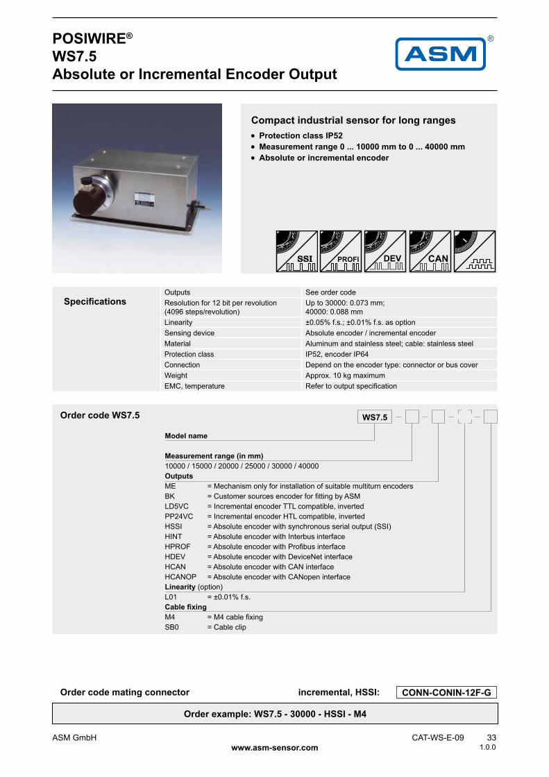
WS7.5Absolute or Incremental Encoder Output
Compact industrial sensor for long ranges • Protection class IP52 • Measurement range 0 ... 10000 mm to 0 ... 40000 mm • Absolute or incremental encoder
Order code WS7.5
Model name
Measurement range (in mm)10000 / 15000 / 20000 / 25000 / 30000 / 40000OutputsME = Mechanism only for installation of suitable multiturn encodersBK = Customer sources encoder for fitting by ASMLD5VC = Incremental encoder TTL compatible, invertedPP24VC = Incremental encoder HTL compatible, invertedHSSI = Absolute encoder with synchronous serial output (SSI)HINT = Absolute encoder with Interbus interfaceHPROF = Absolute encoder with Profibus interfaceHDEV = Absolute encoder with DeviceNet interfaceHCAN = Absolute encoder with CAN interfaceHCANOP = Absolute encoder with CANopen interfaceLinearity (option)L01 = ±0.01% f.s.Cable fixingM4 = M4 cable fixingSB0 = Cable clip
SpecificationsOutputs See order codeResolution for 12 bit per revolution(4096 steps/revolution)
Up to 30000: 0.073 mm; 40000: 0.088 mm
Linearity ±0.05% f.s.; ±0.01% f.s. as optionSensing device Absolute encoder / incremental encoderMaterial Aluminum and stainless steel; cable: stainless steelProtection class IP52, encoder IP64Connection Depend on the encoder type: connector or bus coverWeight Approx. 10 kg maximumEMC, temperature Refer to output specification
Order code mating connector incremental, HSSI:
Order example: WS7.5 - 30000 - HSSI - M4
1.0.0

44,72 1.7600.079[ ]
296 [11.654]13
9[5
.472
]
310 [12.205]
283 [11.142]
142,
8[5
.622
]
8[0
.315
]
583 2.2890.118[ ]
50,5
[1.9
88]
30[1
.181
]
110 [4.331]
24,5
[0.9
65]
34,5
[1.3
58]
6,
1[0
.240
]
14 [0.551]
4x 5,5
M4
OptionSB0
189 [7.441]
199 [7.835]
13,5 [0.531]
34 CAT-WS-E-09 ASM GmbH www.asm-sensor.com
POSIWIRE®
WS7.5Analog, Absolute or Incremental Encoder Output
Cable forces,typical at 20 °C
Range Max. pull-out force Min- pull-in force[mm] [N] [N]
10000 - 30000 8.0 4.240000 7.0 3.4
Outline drawing analog output
Dimensions informative only.For guaranteed dimensions consult factory.
Dimensions in mm [inch]
1.0.0

70,5 [2.776]
296 [11.654]
139
[5.4
72]
44,72 1.7600.079[ ]
583 2.2830.118[ ]
50,5
[1.9
88]
6,
1[0
.240
]
4x 5,5
79,5
[3.1
30]
24,5
[0.9
65]
14 [0.551]
310 [12.205]
8[0
.315
]
142,
8[5
.622
]
283 [11.142]
D
L
F
Maße D, F und L je nach Encodertyp und Befestigung(Dimensions D, F and L are up to encodertyp and the way of mounting)
Montageflansch von ASM
Befestigungsflansch von ASM
Steckbares Kupplungsteil von ASM
OptionSB0
189 [7.441]
199 [7.835]
30[1
.181
]
8,5 [0.335]
ASM GmbH CAT-WS-E-09 35 www.asm-sensor.com
POSIWIRE®
WS7.5Analog, Absolute or Incremental Encoder Output
Dimensions for encoder mounting
Connectable coupling in two parts (output ME)
The outer part of the coupling should be fitted to the encoder shaft. Adjust a 0.5 mm clea-rance between the fastening and the mounting flanges to give an initial tension on the coupling when the mounting bolts are tightened.
Output ME
Dimensions informative only.For guaranteed dimensions consult factory.
Dimensions in mm [inch]
Fastening flange by ASM
Mounting flange by ASM
Connectable coupling by ASM
Dimensions E, F and L depend on the encoder type and mounting.
Outline drawing encoder output
1.0.0

CONN-M12-8F
10V
0 ...10 V
58 CAT-WS-E-09 ASM GmbH www.asm-sensor.com
Voltage divider R1KPotentiometer
Excitation voltage 32 V DC max. at 1 kΩ (max. power 1 W)Potentiometer impedance 1 kΩ ±10 %Thermal coefficient ±25 x 10-6 / °C f.s.Sensitivity Depends on the measuring range, individual
sensitivity of the sensor is specified on the labelVoltage divider utilization range Approx. 3 % ... 97 %Operating temperature -20 ... +85 °C
POSIWIRE®
R1K and 10VAnalog Output
Signal conditioner 10V and 10V5Voltage output
Excitation voltage 18 ... 27 V DC non stabilizedExcitation current 20 mA max.Output voltage 10V: 0 ... 10 V DC; 10V5: 0.5 ... 10 V DCOutput current 2 mA max.Output load > 5 kΩStability (temperature) ±50 x 10-6 / °C f.s.Protection Reverse polarity, short circuitOutput noise 0.5 mVRMS
Operating temperature -20 ... +85 °CEMC According EN 61326:2006
Excitation +
Excitation GND
Signal +
Signal GND
Signal wiringSignal name R1K 10V
Cable color
Connector pin no.
+Vin Excitation + White 1GND Excitation GND Brown 2+Vout Signal + Green 3
Signal GND Yellow 4
View to sensor connector
Connection
Output signals
Output signals+Vin
+Vout
GND
The metal wiper of the potentiometer must be protected against current load! Electrical current flow impact on the wiper causes linearity errors and shortens the lifetime of the potentiometer.
More information:http://www.asm-sensor.com/asm/pdf/pro/ws_poti_technote_en.pdf
1.0.0

420A
4 ...20 mA
420T
4 ...20 mA
CONN-M12-8F
ASM GmbH CAT-WS-E-09 59 www.asm-sensor.com
POSIWIRE®
420A and 420TAnalog Output
Signal conditioner 420ACurrent output (2 wire)
Excitation voltage 12 ... 27 V DC non stabilized, measured at the sensor terminals
Excitation current 35 mA max.Output current 4 ... 20 mA equivalent for 0 ... 100 % rangeStability (temperature) ±100 x 10-6 / °C f.s.Protection Reversed polarity, short circuitOutput noise 0.5 mVRMS
Operating temperature -20 ... +85 °CEMC According to EN 61326:2006
Signal +
Signal –
Output signals
Signal conditioner 420TCurrent output (3 wire)
Excitation voltage 18 ... 27 V DC non stabilizedExcitation current 40 mA max.Load resistor 350 Ω max.Output current 4 ... 20 mA equivalent for 0 ... 100 % rangeStability (temperature) ±50 x 10-6 / °C f.s.Protection Reverse polarity, short circuitOutput noise 0.5 mVRMS
Operating temperature -20 ... +85 °CEMC According to EN 61326:2006
Excitation +
Excitation GND
Signal +
Signal wiringSignal name 420A 420T
Cable color
Connector pin no.
Signal + Excitation + White 1Signal – Excitation GND Brown 2
Signal + Green 3
Output signals
View to sensor connector
Connection
1.0.0

CONN-M12-8F
PMUV PMUI
60 CAT-WS-E-09 ASM GmbH www.asm-sensor.com
POSIWIRE®
PMUV / PMUIProgrammable Analog Output
Signal conditioner PMUV / PMUIVoltage or current output (3 wire)
Excitation voltage 18 ... 27 V DCExcitation current 50 mA max.Voltage output PMUV
Output current Output load
0 ... 10 V 10 mA max. 1 kΩ min.
Current output PMUI Working resistance
4 ... 20 mA (3 wire) 500 Ω max.
Scaling Activation of offset and gain adjust Scalable range
Connect with excitation GND (0 V) 90% max. f.s.
Stability (temperature) ±50 x 10-6 / °C f.s.Operating temperature -20 ... +85 °CProtection Reversed polarity, short circuitEMC According to EN 61326:2006
Output signalsExcitation +
Excitation GND
Signal +
Signal GND
Offset
Gain
Signal wiring PMUV / PMUI
Signal name Connector pin no.
Excitation + 1Excitation GND 2Signal + 3Signal GND 4Not used 5Not used 6Offset 7Gain 8
View to sensor connector
Connection
Signal wiring PMUI2Signal name Connector pin no.
Excitation + 1Excitation GND 2Not used 3Not used 4Signal + 5Signal GND 6Offset 7Gain 8
1.0.0

ADCANOP
ASM GmbH CAT-WS-E-09 61 www.asm-sensor.com
POSIWIRE®
ADCANOPA/D Converted CANopen Bus
Signal diagramExcitation +
Excitation GND
CAN-H
CAN-L
Interface ADCANOPCommunication profile CANopen CiA 301 V 4.02, SlaveEncoder profile Encoder CiA 406 V 3.2Error Control Node Guarding, Heartbeat, Emergency MessageNode ID Adjustable via LSSPDO 3 TxPDO, 0 RxPDO, no linking, static mappingPDO Modes Event-/Time triggered, Remote-request,
Sync cyclic/acyclicSDO 1 server, 0 clientCAM 2 camsCertified YesTransmission rates 50 kBaud to 1 MBaud, adjustable via LSSNodes 127 max.Bus connection M12 connector, 5 pinsIntegrated bus terminating resistor NoBus, galvanic isolated No
Specifications Excitation voltage 8 ... 36 V DCExcitation current Typ. 15/30 mA for 24/12 V, max. 100 mAResolution 16 bit f.s.Measuring rate 1 kHz (asynchronous)Stability (temperature) ±50 x 10-6 / °C f.s.Repeatability 1 LSBOperating temperature -20 ... +85 °CProtection Reverse polarity, short circuitDielectric strength 1 kV (V AC, 50 Hz, 1 min.)Environment - EMC Automation EN 61326:2006
View to sensor connector
Signal wiring / connection
Signal name Connector pin no.
Shield 1Excitation + 2GND 3CAN-H 4CAN-L 5
1.0.0

PP530Encoder
CONN-M12-8F
62 CAT-WS-E-09 ASM GmbH www.asm-sensor.com
POSIWIRE®
PP530Incremental Output
Signal conditioner PP530Incremental
Excitation voltage 5 ... 30 V DCExcitation current 25 mA typ. (w/o load), 200 mA max.Output frequency 200 kHz max.Output Linedriver, Push-Pull, CMOS, TTL- and HTL-
compatibleOutput current 30 mA max.Output voltage Depends on the excitation voltage (e.g. to obtain TTL
signals the excitation voltage must be 5 V). Compatible to EIA RS422/RS485
Saturation voltage high/low Ia <10 mA, UB 5 V/24 V: <0.5 V Ia <30 mA, UB 5 V/24 V: <1 V
Stability (temperature) ±20 x 10-6 / °C f.s. (sensor mechanism)Operation temperature -10 ... +70 °CStorage temperature -30 ... +80 °CTransition time positive edge <200 nsTransition time negative edge <200 nsProtection Reverse polarity, short circuitEMC According to EN 61326:2006
Signal diagram Excitation +
Excitation GND
Signal A
Signal ASignal BSignal BSignal Z (reference pulse)
Signal Z
Recommended processing circuit
View to sensor connectorSignal wiring /
connection
Output signal name Connector pin no.
Excitation + 1Excitation GND (0 V) 2Signal A 4Signal A 6Signal B (A + 90°) 3Signal B 5Signal Z (reference pulse) 7Signal Z 8
1.0.0

CONN-CONIN-12F
LD5VC
PP24VC
ASM GmbH CAT-WS-E-09 65 www.asm-sensor.com
POSIWIRE®
LD5VC and PP24VCIncremental Output
Signal conditioner PP24VCIncremental
Interface Push-pull line driver (24 V-HTL)Excitation voltage 10 ... 30 V DCExcitation current 150 mA max. w/o loadOutput frequency 300 kHz max.Output current 100 mA per channelSignal levelUd High at Id=20 mA, Ub=24 V ≥21VUd Low at Id=20 mA, Ub=24 V ≤2.8 VTransition time positive edge <200 nsTransition time negative edge <200 nsStability (temperature) ±20 x 10-6 / °C f.s. (sensor mechanism)Operating temperature -20 ... +85 °CProtection Reverse polarity, short circuit, overvoltageEMC According to EN 61326:2006
Signal conditioner LD5VCIncremental
Interface Line driver RS422Excitation voltage 5 V DC ±10 %Excitation current 150 mA max. w/o loadOutput frequency 300 kHz max.Output current 20 mA per channelSignal levelUd High at Id=20 mA ≥2.5VUd Low at Id=20 mA ≤0.5 VTransition time positive edge <100 nsTransition time negative edge <100 nsStability (temperature) ±20 x 10-6 / °C f.s. (sensor mechanism)Operation temperature -20 ... +85 °CProtection Short circuit, overvoltageEMC According to EN 61326:2006
Signal A
Signal B
Signal Z
Output signals
Signal wiring / connection
Signal name CONN-CONIN-12F, connector pin no.
Excitation + 12Excitation GND (0 V) 10Signal A 5Signal A 6Signal B (A + 90°) 8Signal B 1Signal Z (reference pulse) 3Signal Z 4Fault detection signal Uas 7Shield Housing
View to sensor connector
1.0.0

CONN-M12-8F
GND (0 V)
66 CAT-WS-E-09 ASM GmbH www.asm-sensor.com
POSIWIRE®
ADSI16A/D Converted SSI Output
• Resolution 16 bit, synchronous serial data transmission/SSI • Optional available with 12 bit (ADSI) or 14 bit (ADSI14) resolution • No loss of data at power down • Easy to connect to PLC´s with SSI input circuitry
The sensing device of the ADSI is a precision potentiometer. The position information is given by an analog/digital converter output serialized as a data word. Data transmission takes place by means of the signals CLOCK and DATA. The processing unit (PLC, Micro- com-puter) sends pulse sequences which clock the data transmission with the required transfer rate. With the first falling edge of a pulse sequence the position of the sensor is recorded and stored. The following rising edges control the bit-by-bit A/D conversion, encoding and output of the data word. After a delay time the next new position information will be transmitted.
Description
Signal conditioner ADSI16 A/D converted synchronous serial
Interface EIA RS422, RS485, short-circuit proofExcitation voltage 11 ... 27 V DCExcitation current 200 mA max.Clock frequency 70 ... 500 kHzCode Gray code, continuous progressionDelay between pulse trains 30 µs min.Resolution 16 bit (65536 counts) f.s.;
optional 12 (ADSI) bit resp. 14 bit (ADSI14)Stability (temperature) ±50 x 10-6 / °C f.s.Operating temperature -20 ... +85 °CEMC According to EN 61326:2006
Data format (train of 26 pulses)
Sensor circuit Subsequent circuitCableRecommended processing circuit
Transmission rateCable length Baud rate
< 50 m < 300 kHz< 100 m < 100 kHz
Signal wiringSignal name Connector pin no.
Excitation + 1Excitation GND (0 V) 2CLOCK 3CLOCK 4DATA 5DATA 6Shield not connected
View to sensor connector
Note:Extension of the cable length will reduce the maximum transmission rate.
DATA
DATA
CLOCK
CLOCK
1.0.0
CONN-CONIN-12F
ASM GmbH CAT-WS-E-09 67 www.asm-sensor.com
POSIWIRE®
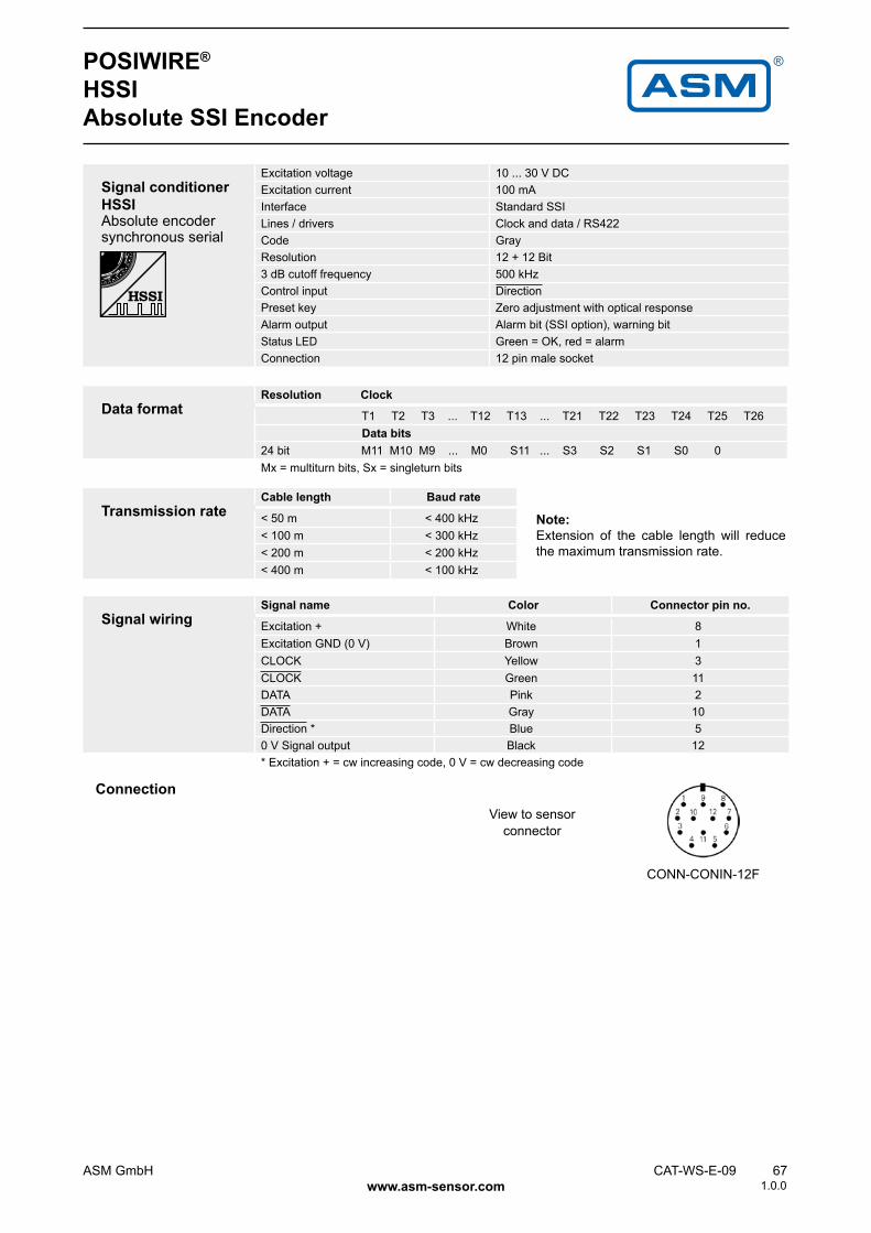
HSSIAbsolute SSI Encoder
Signal conditioner HSSI Absolute encoder synchronous serial
Excitation voltage 10 ... 30 V DCExcitation current 100 mA Interface Standard SSILines / drivers Clock and data / RS422Code GrayResolution 12 + 12 Bit3 dB cutoff frequency 500 kHzControl input DirectionPreset key Zero adjustment with optical responseAlarm output Alarm bit (SSI option), warning bitStatus LED Green = OK, red = alarmConnection 12 pin male socket
Data formatResolution Clock
T1 T2 T3 ... T12 T13 ... T21 T22 T23 T24 T25 T26 Data bits24 bit M11 M10 M9 ... M0 S11 ... S3 S2 S1 S0 0Mx = multiturn bits, Sx = singleturn bits
Transmission rateCable length Baud rate
< 50 m < 400 kHz< 100 m < 300 kHz< 200 m < 200 kHz< 400 m < 100 kHz
Note:Extension of the cable length will reduce the maximum transmission rate.
Signal wiringSignal name Color Connector pin no.
Excitation + White 8Excitation GND (0 V) Brown 1CLOCK Yellow 3CLOCK Green 11DATA Pink 2DATA Gray 10Direction * Blue 50 V Signal output Black 12* Excitation + = cw increasing code, 0 V = cw decreasing code
View to sensor connector
Connection
1.0.0

68 CAT-WS-E-09 ASM GmbH www.asm-sensor.com
POSIWIRE®
HPROFAbsolute Profibus Encoder
Interface HPROF Absolute encoder Profibus
Excitation voltage 10 ... 30 V DCExcitation current 250 mA Interface RS485Protocol Profibus DP with encoder profile C2Resolution 12 (10 ... 14) + 12 bitOutput code BinaryBaud rate Automatically selected between 9,6 kBaud and
12 MBaudProgrammability Resolution, preset, directionIntegrated special functions Velocity, acceleration, operating timeBus terminating resistor Selectable via DIP switchConnection Bus cover with T manifoldEMC EN 61326: class A
Signal wiringSignal name Cable terminal no. (bus cover)
UB in 10V in 2UB out 30V out 4B in 5A in 6B out 7A out 8
1.0.0
ASM GmbH CAT-WS-E-09 69 www.asm-sensor.com
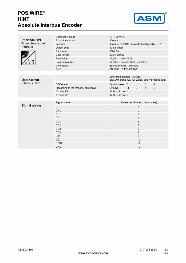
Interface HINT Absolute encoder Interbus
Excitation voltage 10 ... 30 V DCExcitation current 250 mA Interface Interbus, ENCOM profile K3 (configurable), K2Output code 32 Bit binaryBaud rate 500 kBaudData refresh Every 600 µsResolution 12 (10 ... 14) + 12 bitProgrammability Direction, preset, offset, resolutionConnection Bus cover with T manifoldEMC EN 50081-2, EN 50082-2
POSIWIRE®
HINTAbsolute Interbus Encoder
Data format Interbus K2/K3
Differential signals (RS485) ENCOM profile K3, K2, 32 Bit, binary process data
DT-Format Sµpi address 0 1 2 3(according to the Phoenix company) Byte No. 3 2 1 0ID code K2 36 H (= 54 dec.)ID code K3 37 H (= 55 dec.)
Signal wiringSignal name Cable terminal no. (bus cover)
UB + 1GND 2DI1 3DI1 4DO1 5DO1 6DO2 7DO2 8DI2 9DI2 10RBST 11GND 12
1.0.0
70 CAT-WS-E-09 ASM GmbH www.asm-sensor.com
POSIWIRE®
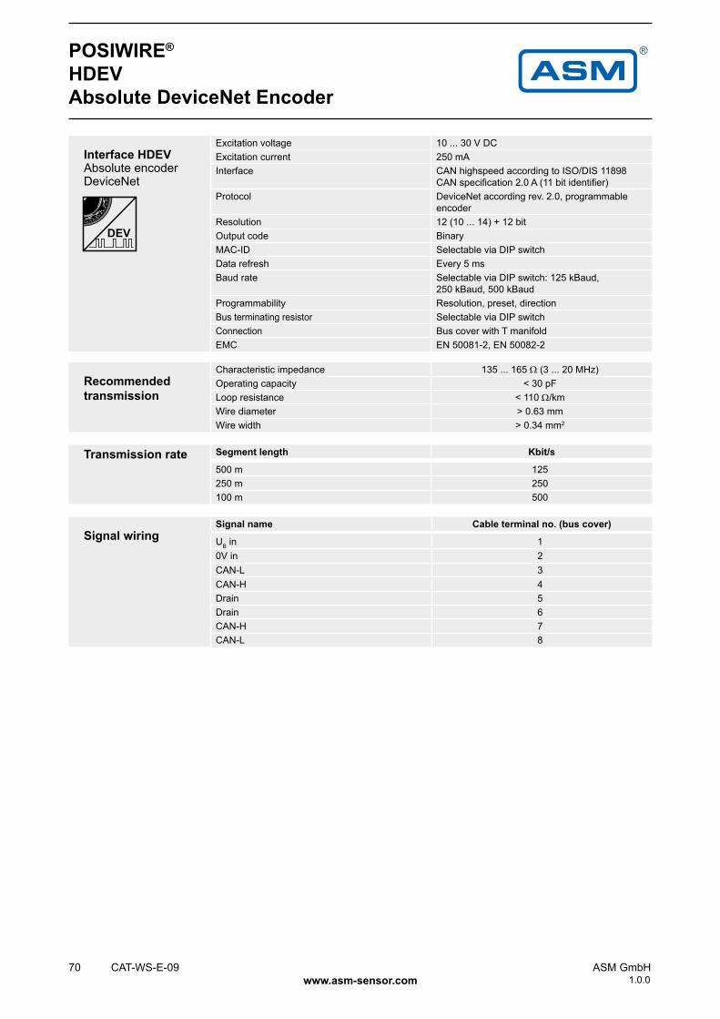
HDEVAbsolute DeviceNet Encoder
Interface HDEV Absolute encoder DeviceNet
Excitation voltage 10 ... 30 V DCExcitation current 250 mA Interface CAN highspeed according to ISO/DIS 11898
CAN specification 2.0 A (11 bit identifier)Protocol DeviceNet according rev. 2.0, programmable
encoderResolution 12 (10 ... 14) + 12 bitOutput code BinaryMAC-ID Selectable via DIP switchData refresh Every 5 msBaud rate Selectable via DIP switch: 125 kBaud,
250 kBaud, 500 kBaudProgrammability Resolution, preset, directionBus terminating resistor Selectable via DIP switchConnection Bus cover with T manifoldEMC EN 50081-2, EN 50082-2
Recommended transmission
Characteristic impedance 135 ... 165 Ω (3 ... 20 MHz)Operating capacity < 30 pFLoop resistance < 110 Ω/kmWire diameter > 0.63 mmWire width > 0.34 mm2
Transmission rate Segment length Kbit/s
500 m 125250 m 250100 m 500
Signal wiringSignal name Cable terminal no. (bus cover)
UB in 10V in 2CAN-L 3CAN-H 4Drain 5Drain 6CAN-H 7CAN-L 8
1.0.0
ASM GmbH CAT-WS-E-09 71 www.asm-sensor.com
POSIWIRE®
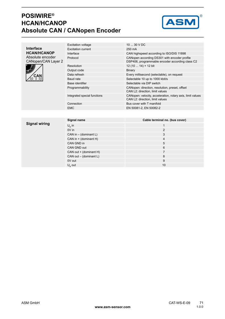
HCAN/HCANOPAbsolute CAN / CANopen Encoder
Interface HCAN/HCANOP Absolute encoder CANopen/CAN Layer 2
Excitation voltage 10 ... 30 V DCExcitation current 250 mA Interface CAN highspeed according to ISO/DIS 11898Protocol CANopen according DS301 with encoder profile
DSP406, programmable encoder according class C2Resolution 12 (10 ... 14) + 12 bitOutput code BinaryData refresh Every millisecond (selectable), on requestBaud rate Selectable 10 up to 1000 kbit/sBase identifier Selectable via DIP switchProgrammability CANopen: direction, resolution, preset, offset
CAN L2: direction, limit valuesIntegrated special functions CANopen: velocity, acceleration, rotary axis, limit values
CAN L2: direction, limit valuesConnection Bus cover with T manifoldEMC EN 50081-2, EN 50082-2
Signal wiringSignal name Cable terminal no. (bus cover)
UB in 10V in 2CAN in – (dominant L) 3CAN in + (dominant H) 4CAN GND in 5CAN GND out 6CAN out + (dominant H) 7CAN out – (dominant L) 80V out 9UB out 10
1.0.0

KAB - XM - M12/8F/W - LITZE
KAB - XM - M12/8F/G - LITZE
KAB - XM - M12/8F/W/69K - LITZE
KAB - XM - M12/8F/G/69K - LITZE
IP69K:
IP69K:
CONN - CONIN - 12F - G
20
~57
18
M12
x1
CONN - M12 - 8F - G
82 CAT-WS-E-09 ASM GmbH www.asm-sensor.com
POSIWIRE®
Accessories for WS® Position Sensors
Connector cable for WS® position sensors8 pin M12
The 8-lead shielded cable is supplied with a mating 8-pin 90° M12 connector at one end and 8 wires at the other end. Available lengths are 2 m, 5 m and 10 m. Wire: cross sectional area 0.25 mm².
Order code:
Length in m
Connector cable wiring - M12, 8 pin
Connector pin / cable color
1 2 3 4 5 6 7 8White Brown Green Yellow Gray Pink Blue Red
Connector cable for WS® position sensors8 pin M12
The 8-lead shielded cable is supplied with a mating 8-pin M12 connector at one end and 8 wires at the other end. Available lengths are 2 m, 5 m and 10 m. Wire: cross sectional area 0.25 mm².
Order code:
Length in m
Connector for WS® position sensors12 pin CONIN
Female connector.
Order code:
Connector for WS® position sensors8 pin M12
Female connector.
Order code:
1.0.0

KAB - XM - M12/5F/G - M12/5M/G - CANKAB - XM - M12/5F/G/69K - M12/5M/G/69K - CANIP69K:
KAB - TCONN - M12/5M - 2M12/5F - CAN
KAB - RTERM - M12/5M/G - CAN
ASM GmbH CAT-WS-E-09 83 www.asm-sensor.com
POSIWIRE®
Accessories for WS® Position Sensors
Connector/bus cable for WS® position sensors5 pin M12 CAN bus/DeviceNet
The 5-lead shielded cable is supplied with a female 5-pin M12 connector at one end and a male 5-pin M12 connector at the other end. Available lengths are 0.3 m, 2 m, 5 m and 10 m.
Order code:
Length in m
Terminating resistance 5 pin M12 CAN bus/DeviceNet
T-piece for bus cable 5 pin M12 CAN bus/DeviceNet Order code:
Order code:
1.0.0