possible short-term introduction of hydrogen as vehicle ... · pdf filelund institute of...
TRANSCRIPT

LUND UNIVERSITY
PO Box 117221 00 Lund+46 46-222 00 00
Possible Short-Term Introduction of Hydrogen as Vehicle Fuel / Fuel Additive
Tunestål, Per; Einewall, Patrik; Stenlåås, Ola; Johansson, Bengt
Published in:Which Fuels For Low CO2 Engines?
Published: 2004-01-01
Link to publication
Citation for published version (APA):Tunestål, P., Einewall, P., Stenlåås, O., & Johansson, B. (2004). Possible Short-Term Introduction of Hydrogenas Vehicle Fuel / Fuel Additive. In P. Duret, & X. Montagne (Eds.), Which Fuels For Low CO2 Engines? (pp.181-188). Editions Technip, Paris.
General rightsCopyright and moral rights for the publications made accessible in the public portal are retained by the authorsand/or other copyright owners and it is a condition of accessing publications that users recognise and abide by thelegal requirements associated with these rights.
• Users may download and print one copy of any publication from the public portal for the purpose of privatestudy or research. • You may not further distribute the material or use it for any profit-making activity or commercial gain • You may freely distribute the URL identifying the publication in the public portalTake down policyIf you believe that this document breaches copyright please contact us providing details, and we will removeaccess to the work immediately and investigate your claim.

Which Fuels For Low CO2 Engines? © P. Duret, X. Montagne (Eds.) and Editions Technip, Paris, 2004, pp. 181-188 27 rue Ginoux, 75015 Paris
POSSIBLE SHORT-TERM INTRODUCTION OF HYDROGEN AS VEHICLE FUEL / FUEL ADDITIVE Per Tunestål, Patrik Einewall, Ola Stenlåås, Bengt Johansson Lund Institute of Technology, Department of Heat & Power Engineering, Lund, Sweden
ABSTRACT –The infrastructure for natural gas distribution can provide the possibility of an evolutionary as opposed to revolutionary introduction of hydrogen as an additive to natural gas (Hythane). In this study, pure natural gas and a hythane blend with 24.8% (vol.) hydrogen have been used to fuel a multi-cylinder heavy-duty natural gas engine.. Some comparisons with pure hydrogen operation are also presented which indicate severely limited load range due to excessive burn rate causing high heat losses. Hythane increases efficiency, reduces CO2 emission and improves the HC-NOX trade-off.
INTRODUCTION
Carbon dioxide (CO2) has been recognized as the most important green house gas responsible for the global warming problem. In order to reduce the amount of CO2 in the atmosphere, the combustion of fossil carbon has to be reduced. This can be achieved by replacing fossil fuels by bio fuels. The plants that the bio fuel is made from absorb as much CO2 when they grow as is subsequently released through combustion. Thus, the net emission of CO2 is zero. The problem with bio fuels is that the plants require a lot of space when they grow and space is a scarce resource in densely populated areas. Another way to reduce the combustion of fossil carbon is by decreasing the total use of energy from combustion. Since the world’s energy consumption is steadily growing, the only way to achieve this is by increasing the efficiency of the devices that utilize combustion. It is also possible to use fossil fuels with a low carbon content. Natural gas e.g. contains about 25% less carbon per heat energy unit compared to gasoline. In [1], natural gas fuelled Internal Combustion (IC) engines are recognized as a viable intermediate step towards hydrogen powered fuel cells. Finally, it is possible to produce
fuels from solar energy, e.g. hydrogen through electrolysis.
There are however problems associated with using hydrogen as a fuel for vehicles. Storing enough hydrogen onboard vehicles is not an easy task. Furthermore, although hydrogen powered fuel cells have a potential for very high fuel efficiency, the cost per kW is prohibitive. Obviously, part of this cost can be reduced by mass production but the cost associated with precious metal content is not reduced by an increasing number of units. There is also the possibility of running an IC engine with hydrogen as fuel, but the combustion properties of hydrogen make it less than ideal. Very promising results are however shown in [2] with both high load and high efficiency achieved using direct injection of hydrogen for an IC engine. Finally, there is no existing infrastructure for hydrogen distribution.
The infrastructure problem can be bridged by gradual introduction of hydrogen into the existing infrastructure for natural gas distribution. Hydrogen then acts as a fuel additive with a certain influence on the combustion process. As the hydrogen fraction in the natural gas increases the properties of the gas will more and more resemble those of hydrogen, and gradual modifications can be made to accommodate these changes. The authors think that this evolutionary approach to hydrogen introduction stands a better chance of success than the revolutionary approach of a completely new system for distribution and energy conversion.
This study investigates the influence of hydrogen addition to natural gas on IC engine combustion, performance and emissions. The measurements are performed on a heavy-duty natural gas engine with various combustion chamber geometries giving different levels of turbulence.

POSSIBLE SHORT-TERM INTRODUCTION OF HYDROGEN AS VEHICLE FUEL / FUEL ADDITIVE 2
EXTENDING THE LEAN LIMIT OF A NATURAL GAS ENGINE
The flame speed of hydrogen is much higher than that of hydrocarbon fuels [3, 4]. Adding hydrogen to natural gas is thus likely to increase the flame speed of the charge. This could be used to extend the lean limit of a natural gas engine to air/fuel ratios where pure natural gas provides insufficient burn rate for stable combustion. A special case of extending the lean limit with hydrogen is presented in [5]. Hydrogen is injected into a prechamber with a spark plug. Partially burned, reacting charge was then injected from the prechamber into the main combustion chamber and served to ignite the charge. This strategy enabled stable engine operation at λ=5. Since the main combustion was essentially that of pure natural gas, there were enormous emissions of HC due to wall and bulk quenching. This phenomenon is not expected with a homogeneous mix of natural gas and hydrogen though. Indeed, [6] shows that the trade-off between NOX and HC for a certain equivalence ratio can be improved by addition of hydrogen.
Another way to increase the flame speed is to introduce charge turbulence. Turbulence of suitable length scale wrinkles the flame front and thus increases its surface area. As an effect, the propagation speed of the reaction zone is increased. The flame speed of a certain charge is essentially proportional to the turbulence intensity and redesign of the combustion chamber for increased turbulence is an alternative way to extend the lean limit. In [7] two different combustion chamber geometries, one with low turbulence and one with high, are operated on a single cylinder engine with various hythane blends. It is concluded that the effects of turbulence and hydrogen addition are to some extent interchangeable.
EXPERIMENTAL SETUP
THE ENGINE
The Engine (TG103/G10A) was originally developed for turbocharged diesel operation and redesigned by Volvo for turbocharged natural gas operation, see Tab. 1 for specifications. The fuel was injected upstream of the turbocharger for enhanced mixing. Natural gas was supplied from the pipeline
whereas hythane was supplied premixed from gas bottles.
Tab. 1 Engine specifications.
Displaced volume/cyl. 1600 cm3
Compression ratio 11.8:1Rated power 184 kW (2000 rpm)Maximum brake torque 1150 Nm (1150 rpm)Bore 120.65 mmStroke 140 mmIgnition sequence 1-5-3-6-2-4
MEASUREMENT SYSTEMS
Cylinder pressure Each cylinder head is equipped with a piezo electric pressure transducer, Kistler 7061B. The signal from the charge amplifier, Kistler 5017A, is processed by two parallel Datel PCI-416 boards in a PC for on-line pressure measurements. The cylinder pressures are measured 5 times per crank angle degree (CAD) using an external clock from a Leine & Linde crank-angle encoder. The pressures are used for heat-release calculations, the program is described in [8]. Pressures are also measured in the inlet manifold (before and after the throttle) and in the exhaust pipe, before the exhaust throttle.
Emissions Emissions are measured after the turbocharger using a Pierburg AMA 2000 emission analyzer. The analyzer consists of; a Heated Flame Ionization Detector (HFID/FID) for hydrocarbons, a Heated Chemiluminescence Detector (HCLD/CLD) for nitric oxides and a Paramagnetic Detector (PMD) for oxygen (O2). The HC emissions are presented as methane equivalent (C1) in the figures. Three Non Dispersive Infra-red Detectors (NDIR) measure carbon monoxide (CO high and low) and carbon dioxide.
In addition to lambda calculations from emission analysis, a lean lambda probe (ETAS) is installed in the exhaust pipe, after the turbocharger.
Flows The mass flow of natural gas is measured with a Bronkhorst F106A-HC.

POSSIBLE SHORT-TERM INTRODUCTION OF HYDROGEN AS VEHICLE FUEL / FUEL ADDITIVE
3
Torque The engine is connected to a Schenk U2-30G water brake, controlled by the engine control system. The torque is measured with a load cell, Nobel Elektronik KRG-4.
All data, except in-cylinder pressure, is collected by a HP 34970A Data Acquisition/Switch unit.
Tab. 2 Natural gas composition
Natural Gas Constituents % Volume
CH4 88.06 C2H6 6.49 C3H8 2.81 C4H10 1.00 C5H12 0.20 C6H14 0.06 CO2 1.05 N2 0.33
RESULTS AND DISCUSSION
The performance and emissions were compared between operation with natural gas and a specific hythane blend (24.8% vol. hydrogen). An intermediate operating point of 7 bar BMEP at 1000 rpm was selected.
TEST MATRIX
Since it is unlikely that the same air/fuel ratio and ignition timing should be optimal for both natural gas and hythane, a whole test matrix was evaluated. The air/fuel ratio was swept between λ=1.0 and λ=1.8 in steps of 0.1, and five different ignition angles from MBT to the stability limit (due to over-retarded ignition) were tested for each air/fuel ratio. The stability limit was defined as the ignition timing where COV(IMEP) is 5%. The design limit on the exhaust temperature is 700° C and served as the limit for the ignition timing in the cases when it was reached before the COV(IMEP) limit. The ignition angles were labeled from a to e where a represents MBT(determined by maximum pressure at 11° ATDC) and e represents the combustion stability limit. Ignition angles b, c and d are evenly distributed between a and e. The ignition
alternatives are illustrated with their respective p-V diagrams in Fig. 1 (natural gas) and Fig. 2 (hythane blend).
0 500 1000 1500 20000
10
20
30
40
50
60
70
Volume (cc)
Pres
sure
(bar
)
Cylinder pressure, NG lambda=1.7
ign=35, aign=30, bign=26, cign=22, dign=18, e
Fig. 1 p-V diagrams for the ignition alternatives a – e for natural
gas at λ=1.7 .
0 500 1000 1500 20000
10
20
30
40
50
60
70
Volume (cc)
Pres
sure
(bar
)Cylinder pressure, NG+H2 lambda=1.7
ign=28, aign=24, bign=20, cign=16, dign=12, e
Fig. 2 p-V diagrams for the ignition alternatives a – e for the
hythane blend at λ=1.7 .
1 1.2 1.4 1.6 1.8 2-45
-40
-35
-30
-25
-20
-15
-10
-5
0
Lambda
Igni
tion
(CA
D A
TDC)
Ignition (a)
NGNG+H2
Fig. 3 Ignition angles for ignition alternative a

POSSIBLE SHORT-TERM INTRODUCTION OF HYDROGEN AS VEHICLE FUEL / FUEL ADDITIVE 4
Fig. 3 shows the selected ignition angles according to ignition alternative a (the most advanced ignition alternative). As expected, the hythane blend has retarded ignition angles relative to pure natural gas due to the higher burn rate indicated in Fig. 4. The heat release rates for natural gas and hythane respectively at λ=1.7 and ignition alternative a are shown in Fig. 5.
1 1.2 1.4 1.6 1.8 210
15
20
25
30
35
40
Lambda
HR1
0-90
(CA
D)
Main combustion duration (CAD, ign (a))
NGNG+H2
Fig. 4 Combustion duration for ignition alternative a.
-20 0 20 40 60 80
0
20
40
60
80
100
120
CAD (ATDC)
dQ (J
/CA
D)
Heat release, ign (a) lambda=1.7
NGNG+H2
Fig. 5 Heat release rates for ignition alternative a at λ=1.7 with
natural gas and hythane blend respectively.
Fig. 6 shows the corresponding ignition angles according to ignition alternative e (the most retarded ignition alternative). The same behavior is observed with the hythane blend requiring retarded ignition angles relative to pure natural gas. It can be seen here also that the ignition timings for 1.2≤λ≤1.4 has been limited to 0 (TDC) since a later ignition timing is not relevant from an efficiency point of view.
1 1.2 1.4 1.6 1.8 2-45
-40
-35
-30
-25
-20
-15
-10
-5
0
Lambda
Igni
tion
(CA
D A
TDC)
Ignition (e)
NGNG+H2
Fig. 6 Ignition angles for ignition alternative e.
Fig. 7 shows the combustion duration for ignition alternative e which is longer since most of the combustion takes place during the expansion stroke with decreasing pressure and temperature. The heat release rates with natural gas and hythane respectively at λ=1.7 and ignition alternative e are shown in Fig. 8. The ignition timings for the three intermediate cases are as mentioned above interpolated between the extremes shown in Fig. 3 and Fig. 6 and the corresponding combustion durations also line up accordingly.
1 1.2 1.4 1.6 1.8 210
15
20
25
30
35
40
Lambda
HR1
0-90
(CA
D)
Main combustion duration (CAD, ign (e))
NGNG+H2
Fig. 7 Combustion duration for ignition alternative e.
POSSIBLE SHORT-TERM INTRODUCTION OF HYDROGEN AS VEHICLE FUEL / FUEL ADDITIVE
5
-20 0 20 40 60 80
0
20
40
60
80
100
120
CAD (ATDC)
dQ (J
/CA
D)
Heat release, ign (e) lambda=1.7
NGNG+H2
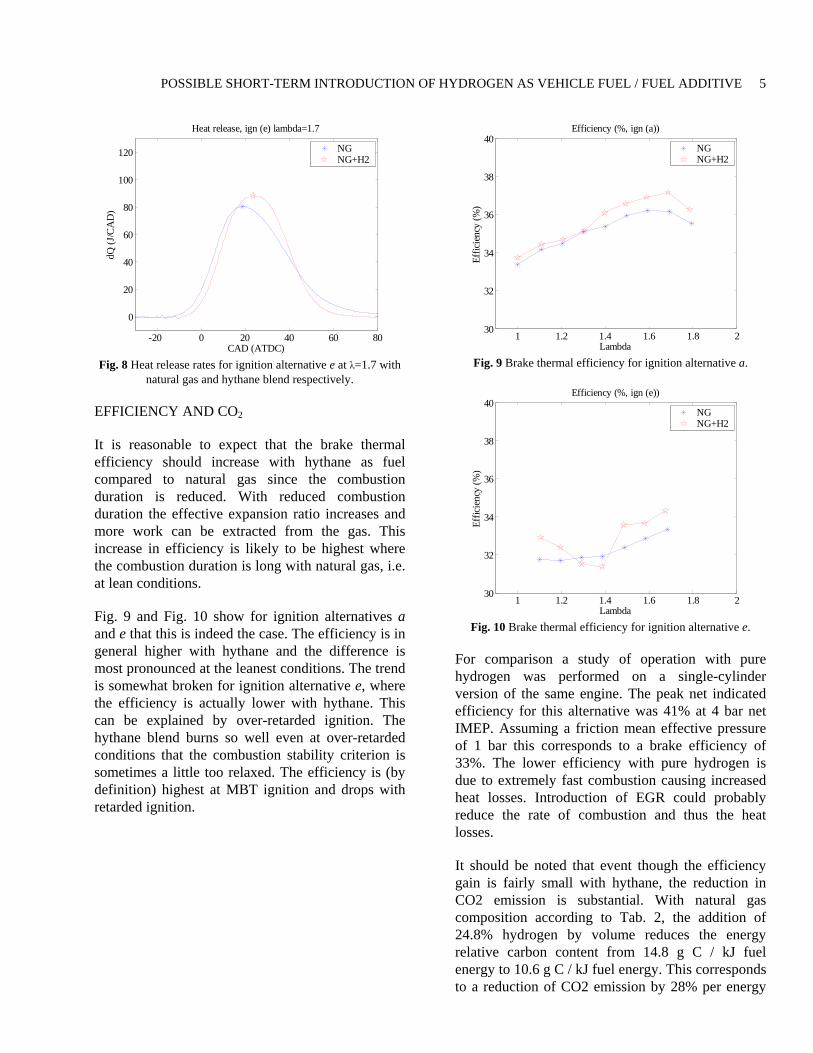
Fig. 8 Heat release rates for ignition alternative e at λ=1.7 with
natural gas and hythane blend respectively.
EFFICIENCY AND CO2
It is reasonable to expect that the brake thermal efficiency should increase with hythane as fuel compared to natural gas since the combustion duration is reduced. With reduced combustion duration the effective expansion ratio increases and more work can be extracted from the gas. This increase in efficiency is likely to be highest where the combustion duration is long with natural gas, i.e. at lean conditions.
Fig. 9 and Fig. 10 show for ignition alternatives a and e that this is indeed the case. The efficiency is in general higher with hythane and the difference is most pronounced at the leanest conditions. The trend is somewhat broken for ignition alternative e, where the efficiency is actually lower with hythane. This can be explained by over-retarded ignition. The hythane blend burns so well even at over-retarded conditions that the combustion stability criterion is sometimes a little too relaxed. The efficiency is (by definition) highest at MBT ignition and drops with retarded ignition.
1 1.2 1.4 1.6 1.8 230
32
34
36
38
40
Lambda
Effic
ienc
y (%
)
Efficiency (%, ign (a))
NGNG+H2
Fig. 9 Brake thermal efficiency for ignition alternative a.
1 1.2 1.4 1.6 1.8 230
32
34
36
38
40
Lambda
Effic
ienc
y (%
)
Efficiency (%, ign (e))
NGNG+H2
Fig. 10 Brake thermal efficiency for ignition alternative e.
For comparison a study of operation with pure hydrogen was performed on a single-cylinder version of the same engine. The peak net indicated efficiency for this alternative was 41% at 4 bar net IMEP. Assuming a friction mean effective pressure of 1 bar this corresponds to a brake efficiency of 33%. The lower efficiency with pure hydrogen is due to extremely fast combustion causing increased heat losses. Introduction of EGR could probably reduce the rate of combustion and thus the heat losses.
It should be noted that event though the efficiency gain is fairly small with hythane, the reduction in CO2 emission is substantial. With natural gas composition according to Tab. 2, the addition of 24.8% hydrogen by volume reduces the energy relative carbon content from 14.8 g C / kJ fuel energy to 10.6 g C / kJ fuel energy. This corresponds to a reduction of CO2 emission by 28% per energy

POSSIBLE SHORT-TERM INTRODUCTION OF HYDROGEN AS VEHICLE FUEL / FUEL ADDITIVE 6
unit. This is in addition to the 25% reduction with natural gas compared to gasoline. Compared to operation with gasoline the reduction in CO2 emission is 45% assuming the same brake efficiency.
EMISSIONS
When an engine is operated part load with a specific combustion timing, e.g. MBT, there is an infinite number of air/fuel ratios that can be used for each load. The air/fuel ratio that is used will affect the emissions and, specifically, there is a trade-off between HC emisssions and NOX emissions. With lean operation, HC emissions increase and NOX emissions decrease with increasing air/fuel ratio. HC emissions increase due to combustion instability. Combustion is too slow to complete before the temperature drops during the expansion stroke. The NOX emissions decrease because the maximum temperature decreases with more air for essentially the same amount of fuel. It is expected that this trade-off should be affected by the addition of hydrogen to the natural gas since it reduces the combustion duration.
Fig. 11 - Fig. 15 show that this is indeed the case. For equal NOX emission levels the reduction in HC emissions is 1-2 g/kWh. All of this can not be attributed to faster combustion. There is also the reduced carbon content in the fuel and the increased efficiency.
0 5 10 150
5
10
15
20
25
30
35
40
HC (g/kWh)
NO
x (g
/kW
h)
NOx vs. HC, advanced ignition (ign (a))
NGNG+H2
Fig. 11 Comparison between HC-NOX trade-off between natural
gas and hythane for ignition alternative a.
0 5 10 150
5
10
15
20
25
30
35
40
HC (g/kWh)
NO
x (g
/kW
h)
NOx vs. HC, ignition (b)
NGNG+H2
Fig. 12 Comparison between HC-NOX trade-off between natural
gas and hythane for ignition alternative b.
0 5 10 150
5
10
15
20
25
30
35
40
HC (g/kWh)
NO
x (g
/kW
h)
NOx vs. HC, ignition (c)
NGNG+H2
Fig. 13 Comparison between HC-NOX trade-off between natural
gas and hythane for ignition alternative c.
0 5 10 150
5
10
15
20
25
30
35
40
HC (g/kWh)
NO
x (g
/kW
h)
NOx vs. HC, ignition (d)
NGNG+H2
Fig. 14 Comparison between HC-NOX trade-off between natural
gas and hythane for ignition alternative d.

POSSIBLE SHORT-TERM INTRODUCTION OF HYDROGEN AS VEHICLE FUEL / FUEL ADDITIVE
7
0 5 10 150
5
10
15
20
25
30
35
40
HC (g/kWh)
NO
x (g
/kW
h)NOx vs. HC, retarded ignition (ign (e))
NGNG+H2
Fig. 15 Comparison between HC-NOX trade-off between natural
gas and hythane for ignition alternative e.
The linear representation of the NOX emissions for ignition alternative e does not reveal the whole truth. In Fig. 16 the NOX emissions are represented logarithmically instead which reveals that the specific NOX emissions are merely 0.06 g/kWh at the leanest operating point. This is well below any NOX regulations and thus NOX after treatment is not necessary.
0 5 10 15
10-1
100
101
HC (g/kWh)
NO
x (g
/kW
h)
NOx vs. HC, retarded ignition (ign (e))
NGNG+H2
Fig. 16 Comparison between HC-NOX trade-off between natural
gas and hythane for ignition alternative e. Logarithmic representation of NOX emissions.
CONCLUSION
Operation with hythane (24.8% vol. hydrogen) and natural gas have been compared for a heavy-duty natural gas engine. The study reveals a small increase in efficiency with hythane. The increase is probably due to faster combustion which increases the effective expansion ratio which allows more work to be extracted. The reduction in CO2 emission
is however substantial, 28% due to the reduced carbon content per energy unit alone. Compared to operation with gasoline the reduction in CO2 emission is 45%, assuming equal efficiency. A comparing single-cylinder study with pure hydrogen revealed a significantly lower efficiency due to increased heat losses.
The trade-off between HC and NOX emissions parameterized by the air/fuel ratio was compared between hythane and natural gas operation for a five different ignition timing alternatives between MBT and the ignition retard limit. The study shows that the trade-off is improved with hythane. For equal NOX emission levels hythane operation, in general, emits 1-2 g/kWh less HC. It is also noted that the specific NOX at the leanest operating point is as low as 0.06 g/kWh which is well below regulations without after-treatment.
It should be noted that the hydrogen content presented in this paper is high enough that some existing natural gas engines may experience decreased performance / efficiency due to the fact that they have been optimized for the existing natural gas quality. Some modification of the engine management may be necessary to take advantage of the change in fuel properties. Bearing this in mind it is the view of the authors that a gradual introduction of hydrogen inte the existing natural gas distribution is a sound way of evolutionary as opposed to revolutionary introduction of hydrogen as fuel.
Acknowledgments. This research was funded by the Swedish Energy Agency (STEM) through the Hythane bus project in the city of Malmö, Sweden. The partners in this project are: Sydkraft, Sydkraft Gas, Swedish Gas Center, Skånetrafiken and Lund Institute of Technology.
REFERENCES
1. Hekkert, M. P., Faaij, A. P. C., Hendriks, F., Neelis, M. L. (2003), Natural gas as an alternative to crude oil in automotive fuel chains well-to-wheel analysis and transition strategy development, Journal of Energy Policy, In Press, doi:10.1016/j.enpol.2003.08.018
2. Berckmüller, M. (2003), Potential of a Charged SI-Hydrogen Engine, SAE Paper No. 2003-01-3210
3. Strahle, W. C. (1993), An Introduction to Combustion, Combustion Science and Technology

POSSIBLE SHORT-TERM INTRODUCTION OF HYDROGEN AS VEHICLE FUEL / FUEL ADDITIVE 8
Book Series, Vol. 1, Gordon and Breach Publishers, Amsterdam
4. Apostolescu, N., Chiriac, R. (1996), A Study of Hydrogen-Enriched Gasoline in a Spark Ignition Engine, SAE Paper No. 960603
5. Lumsden, G., Watson, H. C. (1995), Optimum Control of an S.I. Engine with a λ=5 Capability, SAE Paper No. 950689
6. Collier, K., Hoekstra, R. L., Mulligan, N., Jones, C., Hahn, D. (1996), Untreated Exhaust Emissions of a Hydrogen Enriched CNG Production Engine Conversion, SAE Paper No. 960858
7. Tunestål, P., Christensen, M., Einewall, P., Andersson, T., Johansson, B., Jönsson, O. (2002), Hydrogen Addition for Improved Lean Burn Capability of Slow and Fast Burning Natural Gas Combustion Chambers
8. Johansson, B. (1995), On Cycle to Cycle Variations in Spark Ignition Engines, Doctoral Thesis, Lund Institute of Technology
Contact. Per Tunestål received his PhD 2000 in Mechanical Engineering at the University of California, Berkeley. He currently holds a position as Assistant Professor at the Department of Heat & Power Engineering, Lund Institute of Technology.
e-mail: Web: http://www.vok.lth.se
DEFINITIONS, ACRONYMS, ABBREVIATIONS
ATDC After Top Dead Center BMEP Brake Mean Effective Pressure COV Coefficient Of Variation (mean/std. dev) IMEP Indicated Mean Effective Pressure Hythane Blend of natural gas and hydrogen HC Hydrocarbon IC Internal Combustion (as in IC Engine) λ Air excess ratio MBT Maximum Brake Torque (ignition timing) NO Oxides of nitrogen TDC Top Dead Center
X