post mortem for a wireless emg system, is anwhitmore/courses/ensc305/projects/2002/wmdpost.pdfthe...
TRANSCRIPT
December 11, 2002
Dr. Andrew RawiczSchool of Engineering ScienceSimon Fraser UniversityBurnaby, British ColumbiaV5A 1S6
Subject: Post Mortem for ENSC 340: Wireless EMG Electrodes
Dear Dr. Rawicz:
The document enclosed with this letter, Post Mortem for a Wireless EMG System, is anoutline of the technical and interpersonal experiences during ENSC 340. The goal of ourproject was to develop a system to sense, acquire and wirelessly transmit muscle activitydata from a patient to a computer. Without wires limiting the patient’s freedom ofmotion, this novel technology could revolutionize many aspects of rehabilitation,diagnosis and research.
In this document we present the current state of the device, deviations from the originalspecifications, and our future plans for the device. In addition, there is discussion on ourbudget, time management and personal experiences.
Wireless Medical Devices was formed in June of 2002 by four highly skilled andmotivated Engineering Science students: Eric Chow, Aaron Ridinger, David Press, andAndrew Pruszynski. We look forward to hearing your comments on our proposal. Pleasefeel free to contact us at [email protected].
Sincerely,
Jedrzej (Andrew) PruszynskiChief Executive OfficerWireless Medical DevicesEnclosure: Proposal for Wireless EMG Electrodes

Process Report for a Wireless EMG System
Project Team: Eric ChowDave PressAndrew PruszynskiAaron Ridinger
Submitted To: Dr. Andrew RawiczMr. Steve Whitmore
Revision Number: 1.0
Revision Date: December 13, 2002

1
Process Report for a Wireless EMG System
Copyright 2002 Wireless Medical Devices.
Table of Contents1.0 - INTRODUCTION ................................................................................................................................ 3
2.0 - CURRENT DEVICE............................................................................................................................ 4
2.1 – EMG Pad...................................................................................................................................... 42.2 – TGE Module ................................................................................................................................. 52.3 – Receiver Station............................................................................................................................ 62.4 – PC Software.................................................................................................................................. 8
3.0 – FUTURE PLANS................................................................................................................................. 9
3.1 – More TGEs ................................................................................................................................... 93.2 – New Chipcon Transceiver ............................................................................................................ 93.3 – Miniaturization............................................................................................................................. 93.4 – Acquire Other Biological Signals............................................................................................... 103.5 – Increased Battery Life ................................................................................................................ 103.6 – Fully Independent Wireless EMG............................................................................................... 10
4.0 – PERSONAL EXPERIENCE............................................................................................................. 10
4.1 – Andrew Pruszynski ..................................................................................................................... 104.2 – Eric Chow................................................................................................................................... 114.3 – David Press ................................................................................................................................ 114.4 – Aaron Ridinger........................................................................................................................... 12
5.0 – TIMELINE......................................................................................................................................... 13
6.0 – BUDGET............................................................................................................................................. 14
7.0 – CONCLUSION .................................................................................................................................. 15
APPENDIX.................................................................................................................................................. 16
Transmitter Microcontroller Code (Assembly) ................................................................................... 16Receiver Microcontroller Code (Assembly) ........................................................................................ 23PC Software (C) .................................................................................................................................. 32PC Software (Matlab) ......................................................................................................................... 39
2
Process Report for a Wireless EMG System
Copyright 2002 Wireless Medical Devices.
Acronyms
CMNR Common Mode Noise RejectionDAQ Data AcquisitionECG ElectrocardiogramEEG ElectroencephalogramEMG ElectromyographGUI Graphical User InterfaceiEMG Independent ElectromyographISM Industrial, Scientific, and MedicalI/O Input/OutputMUX MultiplexerNRZ Non-Return to ZeroPC Personal ComputerPCB Printed Circuit BoardPCI Peripheral Card InterfaceRSSI Received Signal Strength IndicatorTGE Transmitter and Ground ElectrodeWMD Wireless Medical Devices
3
Process Report for a Wireless EMG System
Copyright 2002 Wireless Medical Devices.
1.0 - Introduction
An Electromyograph is a recording of muscle activity used for rehabilitation, injuryprevention and performance enhancement. Unfortunately, current systems rely on the useof restrictive wires and equipment that result in inaccurate and inconvenient diagnosis.Applying wireless communications principles to Electromyography (EMG) will leaddirectly to better diagnosis, research and rehabilitation. These advances have far-reachingimplications for corporations, insurance agencies, athletes and patients.
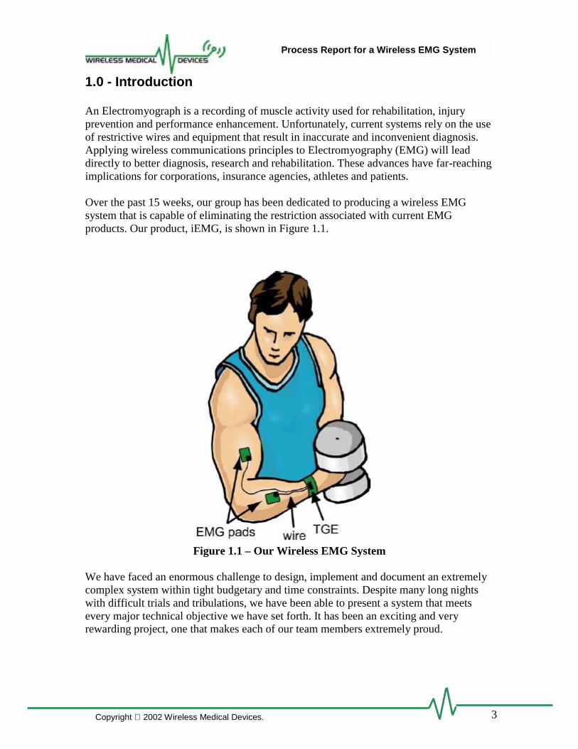
Over the past 15 weeks, our group has been dedicated to producing a wireless EMGsystem that is capable of eliminating the restriction associated with current EMGproducts. Our product, iEMG, is shown in Figure 1.1.
Figure 1.1 – Our Wireless EMG System
We have faced an enormous challenge to design, implement and document an extremelycomplex system within tight budgetary and time constraints. Despite many long nightswith difficult trials and tribulations, we have been able to present a system that meetsevery major technical objective we have set forth. It has been an exciting and veryrewarding project, one that makes each of our team members extremely proud.
4
Process Report for a Wireless EMG System
Copyright 2002 Wireless Medical Devices.
2.0 - Current Device
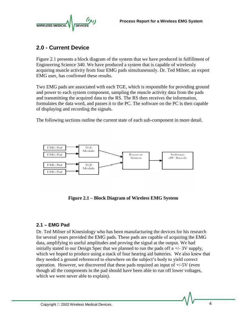
Figure 2.1 presents a block diagram of the system that we have produced in fulfillment ofEngineering Science 340. We have produced a system that is capable of wirelesslyacquiring muscle activity from four EMG pads simultaneously. Dr. Ted Milner, an expertEMG user, has confirmed these results.
Two EMG pads are associated with each TGE, which is responsible for providing groundand power to each system component, sampling the muscle activity data from the padsand transmitting the acquired data to the RS. The RS then receives the information,formulates the data word, and passes it to the PC. The software on the PC is then capableof displaying and recording the signals.
The following sections outline the current state of each sub-component in more detail.
Figure 2.1 – Block Diagram of Wireless EMG System
2.1 – EMG PadDr. Ted Milner of Kinesiology who has been manufacturing the devices for his researchfor several years provided the EMG pads. These pads are capable of acquiring the EMGdata, amplifying to useful amplitudes and proving the signal at the output. We hadinitially stated in our Design Spec that we planned to run the pads off a +/- 3V supply,which we hoped to produce using a stack of four hearing aid batteries. We also knew thatthey needed a ground referenced to elsewhere on the subject’s body to yield correctoperation. However, we discovered that these pads required an input of +/-5V (eventhough all the components in the pad should have been able to run off lower voltages,which we were never able to explain).

5
Process Report for a Wireless EMG System
Copyright 2002 Wireless Medical Devices.
2.2 – TGE ModuleEach TGE module is capable of sampling and transmitting the muscle activity signalfrom two EMG pads at a rate high enough to ensure that no data significant data is lost. Ablock diagram of the TGE is presented in Figure 2.2.
Figure 2.2 – Block Diagram of the TGE Module
TGE Hardware
As mentioned, we initially planned on using a stack of hearing aid batteries to power theTGE. However, after discovering our need a total of 10V, we decided that would simplyrequire too many hearing aid batteries. Thus we decided to use a DC-DC voltageconverter and a lower voltage battery. We decided on a 3V lithium cell, which couldsource enough current to run the EMG pads at over triple its own voltage, while stillhaving sufficient voltage to run the Chipcon transmitter and PIC microcontroller (whichrequire 2.7-3.3 Volts).
When we ran the power supply system as described above, we found that the voltageconverter drew enormous current spikes from the battery, which caused a voltage swingof about 0.2 Volts in the battery’s output. This proved to be too much variation for thePIC to run properly. Thus, we decided to draw the power for the PIC and Chipcon fromthe 10V supply through a 3.3V regulator. This was extremely power inefficient since theChipcon draws more current than all of the EMG hardware combined, but we faced noother options short of purchasing more DC-DC converters to step the voltage down from10V to 3.3V.
This method now allowed us to use batteries that supplied less than 3V (since the MaximDC-DC converters we used accepted supply voltages as low as 1.8V). We then decidedto produce one TGE running off the 3V lithium cells we had already bought, and anotheroff of a pair of rechargeable AAA Ni-MH batteries. The complete TGE including twoEMG pads drew 225 mA at a supply voltage of 2.8V, and this current requirementincreased as the input voltage to the DC-DC converter decreased. We found that a singlelithium cell could run the TGE for 6 hours continuously, while the 2 AAA’s ran in forslightly over 2.5 hours.
EMG Voltage Divider Buffer
EMG Voltage Divider Buffer
PIC Chipcon
microcontroller transmitter
EMG Voltage Divider Buffer
EMG Voltage Divider Buffer
PIC Chipcon
microcontroller transmitter

6
Process Report for a Wireless EMG System
Copyright 2002 Wireless Medical Devices.
Several hardware components were designed to adjust the EMG signal before sending itto the PIC Microcontroller for A/D conversion. The EMG signal varied between +10 and0 volts, whereas the input to the PIC A/D converter needed to be between 3.3 and 0 volts.A simple 2-resistor voltage divider was added to vary the EMG signal between 3.3 and 0volts, and a buffer was added before the PIC A/D input to prevent the converter fromloading the circuit. The buffer was constructed using an OP-AMP in a negative feedbackconfiguration. Initially a generic TLO72 opamp chip was used, but we found that thenegative rail wasn’t close enough to 0 volts, the negative power supply. To ensure thecomplete range down to zero volts, a rail-to-rail opamp was used.
We also faced some choices with regards to the transmitter antenna. After experimentingwith various loops of wire, as well as integrated helical and loop antennas from AntennaFactor, we decided on a small helical antenna called the Antenna Factor JJB.
TGE Firmware
The firmware running on the TGE PIC is much the same as we had initially planned.Essentially, it samples the two A/D channels once per millisecond, and sends the samplesto the Receiver Station.
We initially had hoped to use NRZ format data encoding, which allowed a maximumdata rate of 76.8 kB/s. This allowed us to send every data sample twice, with achecksum, to reduce data errors. We also needed to send an identifier byte everymillisecond before sending a set of data samples so the receiver would be able tosynchronize to the incoming data stream. We found that errors in this start byte weremuch more catastrophic than in the data itself. Thus, the redundant data did little to helpthe overall sample error rate. The data rate wasn’t high enough to send the samples twicein two separate packets with separate identifier bytes.
Thus, we decided to switch to Manchester encoding, which offered a lower data rate of38.4 kB/s, but higher receiver sensitivity and thus fewer bit errors. Since each datasample was only sent once, there was no need for checksums, so we could just barely fiteach packet into the allotted 1 millisecond time slot.
2.3 – Receiver Station
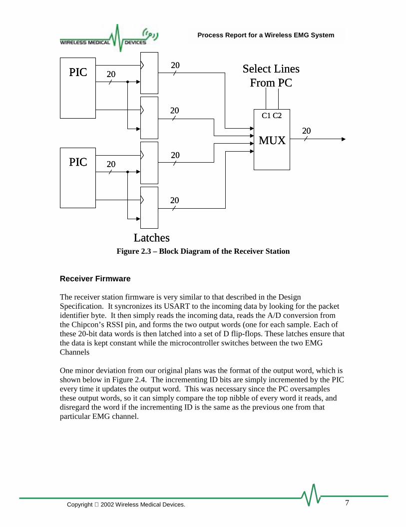
The RS is capable of receiving data from up two TGE modules, formulating the correctdata structure and communicating this to the PC. A block diagram of the RS is presentedin Figure 2.3.
7
Process Report for a Wireless EMG System
Copyright 2002 Wireless Medical Devices.
Figure 2.3 – Block Diagram of the Receiver Station
Receiver Firmware
The receiver station firmware is very similar to that described in the DesignSpecification. It syncronizes its USART to the incoming data by looking for the packetidentifier byte. It then simply reads the incoming data, reads the A/D conversion fromthe Chipcon’s RSSI pin, and forms the two output words (one for each sample. Each ofthese 20-bit data words is then latched into a set of D flip-flops. These latches ensure thatthe data is kept constant while the microcontroller switches between the two EMGChannels
One minor deviation from our original plans was the format of the output word, which isshown below in Figure 2.4. The incrementing ID bits are simply incremented by the PICevery time it updates the output word. This was necessary since the PC oversamplesthese output words, so it can simply compare the top nibble of every word it reads, anddisregard the word if the incrementing ID is the same as the previous one from thatparticular EMG channel.
PIC 2020
20
Latches
PIC 2020
20
MUX20
C1 C2
Select Lines From PC
PICPIC 2020
20
Latches
PICPIC 2020
20
MUX20
C1 C2
Select Lines From PC

8
Process Report for a Wireless EMG System
Copyright 2002 Wireless Medical Devices.
20-Bit Data4 Bits 12 Bits 4 Bits
Incrementing ID EMG Data Signal StrengthFigure 2.4 – Format of Output Word
The output of the latches is connected to multiplexing circuitry that is controlled by thePC DIO Card for use by the software.
We chose to build the RS using spaghetti board rather than design a PCB to save timeand money. We felt that a multi-layer PCB would be more difficult to fix if wediscovered problems, and when we change the design of the receiver station to handlemore TGEs the PCB would have to be redesigned anyways.
The receive side microcontroller source code is presented in the Appendix.
2.4 – PC Software
The PC software serves three major purposes. First, it allows the user to graphicallyobserve the incoming data in real-time. Secondly, the incoming data can be recorded forfuture analysis. Lastly, some Matlab code was written to allow the import andobservation of the acquired data signal.
Real-time graphical observation allows the user to correctly setup the EMG electrodes byensuring correct pad placement and amplification. In addition, the user is shown thesignal strength indicator (via RSSI) from each of the transmitting TGEs. This visualrepresentation of receive signal strength lets the operator decide if the incoming signalstrength is enough to ensure data consistency.
After the system has been verified graphically and the user is satisfied with theexperimental setup, the data acquisition feature can be used to save muscle activity data.When the user begins data acquisition, the system will record the data from each EMGpad into an individual binary data file. The code has been written in such a way thatensures that no data points are lost and that no data points are saved twice.
The Matlab code was written to take advantage of the pre-fabricated GUI interface. Moreimportantly, the ability to import our data files into Matlab is extremely important for theend users who will most likely be performing their data analysis within this softwareenvironment. Since our sampling at the TGE is very synchronous, we can provide theuser with an accurate time-scale for the data stream. In addition, we can guarantee thatthis time scale applies to all the EMG signals recorded in each trial. These are veryimportant features for the user.
We initially planned on a windows based GUI application for our PC software but afterlooking into the requirements and talking with people who have done similar programs,we decided that for this project a windows based GUI would not work. One of the main
9
Process Report for a Wireless EMG System
Copyright 2002 Wireless Medical Devices.
reasons was to have a fast enough sampling time, we had to run the program in DOSbecause there was too much overhead for the API in windows. To be able to operate inwindows, it is estimated that it would take an entire semester of work to write theappropriate device drivers and other software.
The source code for the C-based application software and the Matlab file for data analysisare included in the Appendix.
3.0 – Future Plans
The future for this product is extremely bright. It is ahead of the competition in terms oftechnology and could be produced for a much lower product price. In order to improveour market position and increase our technological advantage, there are severaldevelopments we are planning to make. The following sections outline these changes.
3.1 – More TGEsOur most pressing issue is to expand the number of TGEs we currently have built. Thisdoes not require a redesign of our system, it simply requires manual labour and money toassemble more units. We would also have to expand the receiver station to handle theadditional incoming data. The software is already designed to handle more TGE units. Bymaking all the additional hardware, we will be capable of operating a maximum of 8TGEs supporting up to 16 EMG pads without any significant system design changes.
3.2 – New Chipcon TransceiverChipcon, our supplier of wireless ISM band transceivers has just announced the release ofa new transceiver. This product will be able to handle a higher data rate which wouldallow us to connect more EMG pads to a single TGE or send each sample twice forredundancy and error checking. The new transceiver is also designed specifically fornarrow-band operation. This would allow us to fit more TGEs onto the 915MHz ISMband.
3.3 – MiniaturizationA critical body of work remains to place the design onto a PCB. We decided to avoid thisfor the purpose of this project to maximize our ability to debug the product and save timeand money. Designing a PCB would have many significant effects on the product. Mostimportantly it would reduce the size and weight of the product. We estimate that a finalPCB of the TGE would create a final size of 1.5” by 1.5”. A design for the RS would alsocreate a more compact and reliable package. Product miniaturization is critical to creatingan unobtrusive and high quality product.

10
Process Report for a Wireless EMG System
Copyright 2002 Wireless Medical Devices.
3.4 – Acquire Other Biological SignalsThere are many other biological signals that fall within the same characteristics as EMGin terms of frequency range. Our product has been designed from the very beginning tobe capable of handling these other biological signals. We can transmit any signal fromDC to 500 Hz, and both ECG and EEG are much lower than this limit. We have yet totest this feature and it would be extremely interesting and important to develop our abilityto transmit ECG, EEG, and other patient monitoring signals via the same hardware setup.
3.5 – Increased Battery LifeOur current battery life of 2.5 hours on two rechargeable NiMH batteries and 6 hours onone non-rechargeable lithium is appropriate for EMG data acquisition applications.However, as our system is adapted to other signals, we need to investigate increasing thisbattery life to 24 hours on rechargeable batteries. There are several options that must beinvestigated. First, a different hardware solution on the TGE could eliminate waste due toheat by eliminating voltage regulators. We could use two separate DC-DC converters,one to produce 10V and the other to produce 3.3V. This would cut the currentconsumption of the TGE by a factor of two, more than doubling our battery lifetime.Secondly, there exist proprietary battery technologies that may be better suited in termsof power, size and weight to deliver power to the system.
3.6 – Fully Independent Wireless EMGThe initial goal of our system was to have absolutely no wires on the body.Unfortunately, the pads that were provided by Dr. Ted Milner required an externalground to work properly because of the internal operation of a differential amplifier.Therefore, one major goal is to redesign the EMG pad such that it can be used without theTGE. In this setup the transmitting would be done from each EMG pad directly,eliminating all the wires on the system. Currently, Aaron Ridinger is investigating theopportunity to develop such an EMG pad as his undergraduate thesis.
4.0 – Personal Experience
4.1 – Andrew PruszynskiDeveloping this project has been one of the most rewarding, enjoyable and oftenfrustrating experiences of my education. I have learned many technical and interpersonalskills that I will undoubtedly use for the rest of my life.
From a technical point of view, I have combined all the knowledge that I have gatheredfrom my coursework and coop experience. We have been able to create something fromonly an idea. I developed the C based software which built on my experiences whileworking in the Biomechanics Laboratory and Ballard. I designed and manufactured themother of all spaghetti boards that required digital design knowledge and all the solderingskills and patience that have been developed over the past four years. More important
11
Process Report for a Wireless EMG System
Copyright 2002 Wireless Medical Devices.
then any single discreet contribution to the project was the endless debugging to figureout what was wrong and how to fix it. This has taught me that what is wrong is often themost simple thing, so simple that hours may be spent rejecting it as a possibility.
We have completed a large and difficult task and I am extremely happy with the finaloutcome, the personal experience associated with getting there and the technicalknowledge that I have gained.
4.2 – Eric ChowThis project has shown me that many hours of research and development must go into aproduct in order to ensure a high quality end result. The project required us to work on allaspects of a product design, including research, hardware/software design, assembly andtesting, purchasing and finances, and documentation.
The technical skills I have learned from other courses and jobs enabled me to contributeto the technical design of our project. Notable skills included hardware design, radiofrequency communications, and basic electronics laboratory skills.
My contribution to the team was primarily focused on the research of a suitable RFtransmitter/receiver pair and the TGE hardware design. In addition, I worked on buildingthe prototype and assisted in the microcontroller firmware development.
In working with Andrew, Dave, and Aaron, I have realized the importance of goodcommunication within a group to ensure good team dynamics. Our weekly meetingshelped keep the group on track, and although tasks were divided among us we made sureto that everyone was kept up to date on the status of the project.
I see our product as having great market potential as well as research potential, and Ihope to continue work with this product and this group in the future.
4.3 – David PressI found this project both incredibly frustrating and incredibly rewarding. I have gainedmany skills and experiences that will aid me throughout my career.
Perhaps the most valuable single thing I learned is that when working on a project of thismagnitude, not everything can be perfect. There were many times near the beginningwhen I would spend many hours perfecting a small aspect of the project. Towards theend, I learned that sometimes ‘good enough is good enough’, which is a huge step for meas I am known as a bit of a perfectionist.
My main contribution to this project was the firmware and transmission protocols fortransmitting the data wirelessly. This was the first time I had picked up the manual for acompletely unfamiliar microcontroller, and needed to learn every minute detail and quirkof its operation. I feel much more comfortable that I could do the same again if need be. I
12
Process Report for a Wireless EMG System
Copyright 2002 Wireless Medical Devices.
also gained a lot of experience in haggling and hounding parts suppliers for lower pricesand rushed shipping. I had to communicate frequently with design engineers at Chipconin Norway, which proved to be an interesting cultural and logistical challenge.Overall, I am very pleased that the enormous effort we put into this project early onallowed us to accomplish our ambitious goals with time left to spare at the end of thesemester.
4.4 – Aaron RidingerBy working on this project I have further developed my technical, problem solving andinterpersonal skills. I enjoyed both the technical aspects and team dynamics of thisproject.
New the beginning of this project I learned the many different possibilities of interfacinga PC with external devices such as USB, PCI, ISA, Firewire, and made a decision onwhich would work best for our project based on function and price. By working on thePC software I re-familiarized myself with programming in C, and utilized the Matlabskills I gained through past course work. Near the completion of the project I designedthe TGE hardware and assembled it, which required me to recall my soldering skills Ilearned in high school.
Through this project and other course work this semester, I have discovered that I reallydon’t want to design IC chips, as I initially planned on when I started studyingengineering, but rather work in an area developing products to meet certain needs andsolve specific solutions. After completing this project I now have an interest in bio-medical engineering. In the future I plan on doing a directed studies course in the area ofEMG and mostly likely a thesis on the redesign of the EMG pad to eliminate the groundreference strap.
13
Process Report for a Wireless EMG System
Copyright 2002 Wireless Medical Devices.
5.0 – Timeline
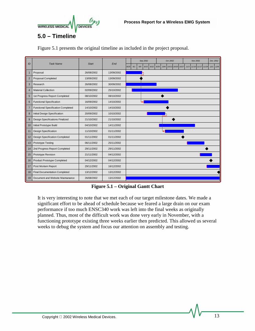
Figure 5.1 presents the original timeline as included in the project proposal.
Figure 5.1 – Original Gantt Chart
It is very interesting to note that we met each of our target milestone dates. We made asignificant effort to be ahead of schedule because we feared a large drain on our examperformance if too much ENSC340 work was left into the final weeks as originallyplanned. Thus, most of the difficult work was done very early in November, with afunctioning prototype existing three weeks earlier then predicted. This allowed us severalweeks to debug the system and focus our attention on assembly and testing.
ID Task Name Start EndSep 2002 Oct 2002 Nov 2002 Dec 2002
8/25 9/1 9/8 9/15 9/22 9/29 10/6 10/13 10/20 10/27 11/3 11/10 11/17 11/24 12/1 12/8
1 13/09/200226/08/2002Proposal
3 30/09/200226/08/2002Research
6 14/10/200216/09/2002Functional Specification
4 25/10/200202/09/2002Material Collection
11 01/11/200211/10/2002Design Specification
10 14/11/200204/10/2002Initial Prototype Build
13 25/11/200206/11/2002Prototype Testing
15 04/12/200221/11/2002Prototype Revision
19 13/12/200226/08/2002Document and Website Maintanance
17 16/12/200229/11/2002Post Mortem Report
8 10/10/200220/09/2002Initial Design Specification
5 08/10/200208/10/20021st Progress Report Completed
7 14/10/200214/10/2002Functional Specification Completed
12 01/11/200201/11/2002Design Specification Completed
14 29/11/200229/11/20022nd Progress Report Completed
16 04/12/200204/12/2002Product Prototype Completed
18 13/12/200213/12/2002Final Documentation Completed
2 13/09/200213/09/2002Proposal Completed
9 21/10/200221/10/2002Design Specifications Finalized
14
Process Report for a Wireless EMG System
Copyright 2002 Wireless Medical Devices.
6.0 – Budget
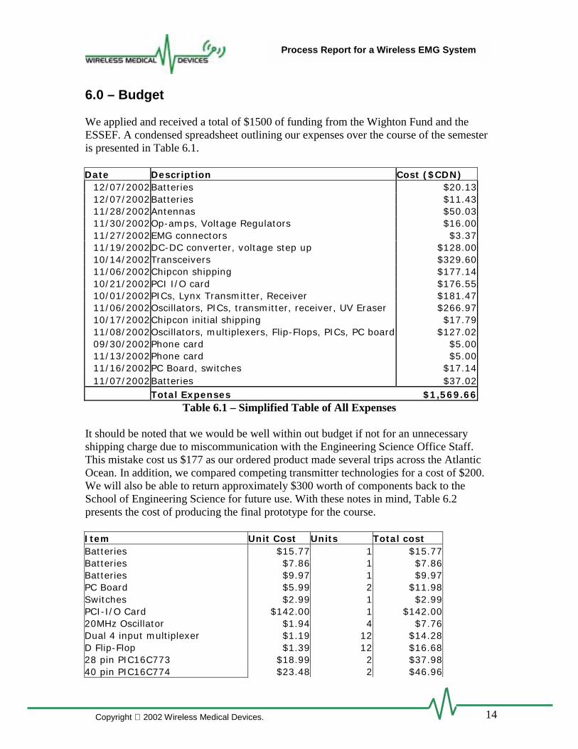
We applied and received a total of $1500 of funding from the Wighton Fund and theESSEF. A condensed spreadsheet outlining our expenses over the course of the semesteris presented in Table 6.1.
Date Description Cost ($CDN)12/07/2002Batteries $20.1312/07/2002Batteries $11.4311/28/2002Antennas $50.0311/30/2002Op-amps, Voltage Regulators $16.0011/27/2002EMG connectors $3.3711/19/2002DC-DC converter, voltage step up $128.0010/14/2002Transceivers $329.6011/06/2002Chipcon shipping $177.1410/21/2002PCI I/O card $176.5510/01/2002PICs, Lynx Transmitter, Receiver $181.4711/06/2002Oscillators, PICs, transmitter, receiver, UV Eraser $266.9710/17/2002Chipcon initial shipping $17.7911/08/2002Oscillators, multiplexers, Flip-Flops, PICs, PC board $127.0209/30/2002Phone card $5.0011/13/2002Phone card $5.0011/16/2002PC Board, switches $17.1411/07/2002Batteries $37.02
Total Expenses $1,569.66Table 6.1 – Simplified Table of All Expenses
It should be noted that we would be well within out budget if not for an unnecessaryshipping charge due to miscommunication with the Engineering Science Office Staff.This mistake cost us $177 as our ordered product made several trips across the AtlanticOcean. In addition, we compared competing transmitter technologies for a cost of $200.We will also be able to return approximately $300 worth of components back to theSchool of Engineering Science for future use. With these notes in mind, Table 6.2presents the cost of producing the final prototype for the course.
Item Unit Cost Units Total costBatteries $15.77 1 $15.77Batteries $7.86 1 $7.86Batteries $9.97 1 $9.97PC Board $5.99 2 $11.98Switches $2.99 1 $2.99PCI-I/O Card $142.00 1 $142.0020MHz Oscillator $1.94 4 $7.76Dual 4 input multiplexer $1.19 12 $14.28D Flip-Flop $1.39 12 $16.6828 pin PIC16C773 $18.99 2 $37.9840 pin PIC16C774 $23.48 2 $46.96
15
Process Report for a Wireless EMG System
Copyright 2002 Wireless Medical Devices.
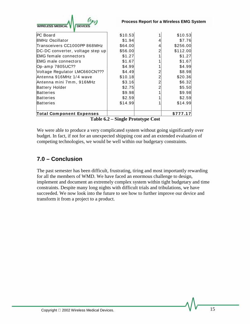
PC Board $10.53 1 $10.538MHz Oscillator $1.94 4 $7.76Transceivers CC1000PP 868MHz $64.00 4 $256.00DC-DC converter, voltage step up $56.00 2 $112.00EMG female connectors $1.27 1 $1.27EMG male connectors $1.67 1 $1.67Op-amp 7805UC?? $4.99 1 $4.99Voltage Regulator LMC660CN??? $4.49 2 $8.98Antenna 916MHz 1/4 wave $10.18 2 $20.36Antenna mini 7mm, 916MHz $3.16 2 $6.32Battery Holder $2.75 2 $5.50Batteries $9.98 1 $9.98Batteries $2.59 1 $2.59Batteries $14.99 1 $14.99
Total Component Expenses $777.17Table 6.2 – Single Prototype Cost
We were able to produce a very complicated system without going significantly overbudget. In fact, if not for an unexpected shipping cost and an extended evaluation ofcompeting technologies, we would be well within our budgetary constraints.
7.0 – Conclusion
The past semester has been difficult, frustrating, tiring and most importantly rewardingfor all the members of WMD. We have faced an enormous challenge to design,implement and document an extremely complex system within tight budgetary and timeconstraints. Despite many long nights with difficult trials and tribulations, we havesucceeded. We now look into the future to see how to further improve our device andtransform it from a project to a product.
16
Process Report for a Wireless EMG System
Copyright 2002 Wireless Medical Devices.
Appendix
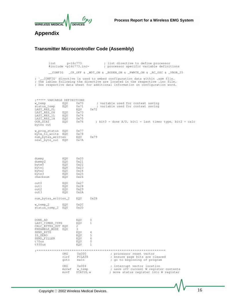
Transmitter Microcontroller Code (Assembly)
list p=16c773 ; list directive to define processor#include <p16c773.inc> ; processor specific variable definitions
__CONFIG _CP_OFF & _WDT_ON & _BODEN_ON & _PWRTE_ON & _RC_OSC & _VBOR_25
; '__CONFIG' directive is used to embed configuration data within .asm file.; The lables following the directive are located in the respective .inc file.; See respective data sheet for additional information on configuration word.
;***** VARIABLE DEFINITIONSw_temp EQU 0x70 ; variable used for context savingstatus_temp EQU 0x71 ; variable used for context savingLAST_RES_0L EQU 0x72LAST_RES_0H EQU 0x73LAST_RES_1L EQU 0x74LAST_RES_1H EQU 0x75OUR_STAT EQU 0x76 ; bit0 = done A/D, bit1 = last timer type, bit2 = calcbytes out
w_prog_status EQU 0x77byte_to_write EQU 0x78num_bytes_written EQU 0x79next_byte_out EQU 0x7A
dummy EQU 0x20dummy2 EQU 0x21byte0 EQU 0x22byte1 EQU 0x23byte2 EQU 0x24byte3 EQU 0x25checksum EQU 0x26
out0 EQU 0x27out1 EQU 0x28out2 EQU 0x29out3 EQU 0x2A
num_bytes_written_2 EQU 0x2B
w_temp_2 EQU 0x2Cstatus_temp_2 EQU 0x2D
DONE_AD EQU 0LAST_TIMER_TYPE EQU 1CALC_BYTES_OUT EQU 2PREAMBLE_MODE EQU 3SEND_BYTE EQU 4IS_ZERO EQU 5SEND_FILLER EQU 6t70us EQU 0t930us EQU 1
;**********************************************************************ORG 0x000 ; processor reset vectorclrf PCLATH ; ensure page bits are clearedgoto main ; go to beginning of program
ORG 0x004 ; interrupt vector locationmovwf w_temp ; save off current W register contentsmovf STATUS,w ; move status register into W register

17
Process Report for a Wireless EMG System
Copyright 2002 Wireless Medical Devices.
movwf status_temp ; save off contents of STATUS register
; isr code can go here or be located as a call subroutine elsewhere;;;;;;; BEGIN ISR ;;;;;;;;;;;;;;;isr
bsf STATUS, RP0 ; page 1
btfss INTCON, T0IFgoto int_was_USART
;;; int for timer
btfss OUR_STAT, LAST_TIMER_TYPEgoto was_70us
; last timer was 930 us
bcf STATUS, RP0 ; page 0movlw 0xEEmovwf TMR0 ; set timer to overflow in 70 us
bsf PORTA, 2
bsf ADCON0, CHS0 ; set next A/D to ch1
movf ADRESH, W ; get ch0 resultmovwf LAST_RES_0Hbsf STATUS, RP0 ; page 1movf ADRESL, Wmovwf LAST_RES_0Lbcf OUR_STAT, LAST_TIMER_TYPE ; last timer now was 70!
goto finish_timer_isr
was_70us bcf STATUS, RP0 ; page 0movlw 0x24movwf TMR0 ; set timer to overflow in 930 usbcf ADCON0, CHS0 ; set next A/D to ch0
movf ADRESH, W ; get ch1 resultmovwf LAST_RES_1Hbsf STATUS, RP0 ; page 1movf ADRESL, Wmovwf LAST_RES_1L
bsf OUR_STAT, LAST_TIMER_TYPE ; last timer was 930bsf OUR_STAT, CALC_BYTES_OUT
finish_timer_isrbcf INTCON, T0IF ; reset the timer0 interupt flag
bcf STATUS, RP0 ; page 0bsf ADCON0, GO_DONE ; start A/D conversion
btfsc OUR_STAT, LAST_TIMER_TYPEgoto end_isr
; last timer was 930 us, update the out0..out3movf byte0,Wmovwf out0movf byte1,Wmovwf out1movf byte2,Wmovwf out2
bcf PORTA, 2
btfsc OUR_STAT, PREAMBLE_MODEgoto end_isr
18
Process Report for a Wireless EMG System
Copyright 2002 Wireless Medical Devices.
movlw 0x01movwf num_bytes_written
goto end_isr
int_was_USART
bcf STATUS, RP0 ; page 0btfss OUR_STAT, PREAMBLE_MODEgoto send_data
send_out_preamble
incf num_bytes_written, Fmovf num_bytes_written, W
sublw 0xFFbtfsc STATUS, Zgoto end_preamblemovlw 0x55movwf TXREGgoto end_isr
end_preamblebcf OUR_STAT, PREAMBLE_MODEmovlw 0x55movwf TXREGmovlw 0x00movwf num_bytes_writtenbsf OUR_STAT, SEND_FILLERclrf num_bytes_writtengoto end_isr
send_data
movlw 0x80
btfsc num_bytes_written, 1movf out0, Wbtfsc num_bytes_written, 2movf out1, Wbtfsc num_bytes_written, 3movf out2, Wbtfsc num_bytes_written, 4movlw 0x55
write_to_txregmovwf TXREG
bcf STATUS, Cbtfss num_bytes_written, 4rlf num_bytes_written, F
goto end_isr
;;;;;;;;; END OF ISR CODE;;;;;;;;;end_isr
movf status_temp,w ; retrieve copy of STATUS registermovwf STATUS ; restore pre-isr STATUS register contentsmovf w_temp, wretfie
;;;;;;;;;; END OF ISR ;;;;;;;;;;;;;;;
main;;;;;; setup ;;;;;;;;;
bcf STATUS, RP1 ; access page 1bsf STATUS, RP0
clrf num_bytes_writtenmovlw 0x08movwf OUR_STATmovlw 0x55movwf next_byte_out
movlw 0x8D ; setup analog/digital IO PA0,PA1 analogmovwf ADCON1

19
Process Report for a Wireless EMG System
Copyright 2002 Wireless Medical Devices.
movlw 0x03 ; PA7..PA2 output PA0, PA1 inputmovwf TRISA
movlw 0x00movwf TRISB ; PORTB outputs
movlw 0x50movwf TRISC ; PC 6,4 input, rest output
movlw 0x02 ; pull ups enabled, int on rise edge, internal clockfor timer0, prescaler to timer0, 1:8 prescaler (Fosc/32)
movwf OPTION_REG
movlw 0x40 ; initialize SSPSTATmovwf SSPSTAT
movlw 0x32 ; initialize USARTmovwf TXSTA
bsf PIE1, TXIE ; enable USART transmit interupt
bcf STATUS, RP0 ; access page 0
movlw 0x80movwf RCSTA
movlw 0x30 ;movwf SSPCON ; enable SPI! must be after SSPSTAT has been written
movlw 0x81 ; A/D TOsc/32, AN0, No Conversion Complete, Onmovwf ADCON0
movlw 0x55 ; put something in USART tx regmovwf TXREG
call config_CC1000_TX
movlw 0xE0 ; global interupt on, , timer0 int on, , ,movwf INTCON
loopbtfss OUR_STAT, CALC_BYTES_OUTgoto loop
; just got out of 70us interupt, calculate the next message bytesbcf STATUS, RP0 ; page 0
movf LAST_RES_0H, W; movlw 0x12 ; REMOVE THIS!!!
andlw 0x0Fmovwf byte0movf LAST_RES_0L, W
; movlw 0x34 ; REMOVE THIS!!!movwf byte1
movf LAST_RES_1H, W; movlw 0x56 ; REMOVE THIS!!!
andlw 0x0Fmovwf byte2movf LAST_RES_1L, W
; movlw 0x78 ; REMOVE THIS!!!movwf byte3
; make byte 0swapf byte0, F
swapf byte1, Wandlw 0x0Fiorwf byte0, F
; make byte 1

20
Process Report for a Wireless EMG System
Copyright 2002 Wireless Medical Devices.
swapf byte1, Fmovlw 0xF0andwf byte1, F
movf byte2, Wandlw 0x0Fiorwf byte1, F
; make byte 2movf byte3, Wmovwf byte2
end_calcbcf OUR_STAT, CALC_BYTES_OUT
goto loop
;;;;;;;;;;;;;;; SUBROUTINES ;;;;;;;;;;;;;
;;;;;;;;;;;;;;;;;;;;;;w_prog_addr
movwf byte_to_writemovf STATUS, Wmovwf w_prog_status
bcf STATUS, RP0bcf STATUS, RP1 ; page 0
bcf PORTC, 2 ; clear PALE
movf w_prog_status, Wmovwf STATUSmovf byte_to_write, W
w_prog_data;;; writes a byte to prog CC1000 thru SPI
movwf byte_to_writemovf STATUS, Wmovwf w_prog_status ; save the current status
bcf STATUS, RP0 ; page 0bcf STATUS, RP1
movf byte_to_write, Wmovwf SSPBUF
bsf STATUS, RP0 ; page 1wait_for_SPI_0 btfss SSPSTAT, BF ; wait for the byte to be written to SPI
goto wait_for_SPI_0
bcf STATUS, RP0 ; page 0bsf PORTC, 2 ; set PALE high
movf w_prog_status, Wmovwf STATUSreturn
;;;;;;;;;;;;;;;;;;;;;;;r_prog
;;;;; reads a byte from CC1000 thru SPI;;;;; returns byte in W regmovf STATUS, Wmovwf w_prog_status ; save the current status
bcf STATUS, RP1bsf STATUS, RP0 ; page 1
bsf TRISC, 5 ; set PC5 (Data out) to input
bcf STATUS, RP0 ; page 0
movwf SSPBUF ; write random crap from W
bsf STATUS, RP0 ; page 1wait_for_SPI_1 btfss SSPSTAT, BF ; wait for the byte to be written to SPI

21
Process Report for a Wireless EMG System
Copyright 2002 Wireless Medical Devices.
goto wait_for_SPI_1
bcf TRISC, 5 ; set PC5 to output
movf w_prog_status, Wmovwf STATUSreturn
;;;;;;;;;;;;;;;;;wait_500us
clrf dummywait1 incf dummy
btfss STATUS, Zgoto wait1return
;;;;;;;;;;;;;;;;;
config_CC1000_TX; make the transmit wake up later than the rx
clrf dummy2wait3 call wait_500us
incf dummy2btfss STATUS, Zgoto wait3
movlw CC1000_MAIN_Wcall w_prog_addrmovlw 0x3Acall w_prog_data
movlw CC1000_MAIN_Wcall w_prog_addrmovlw 0x3Bcall w_prog_data
call wait_500uscall wait_500uscall wait_500uscall wait_500uscall wait_500us
movlw CC1000_FREQ_2A_Wcall w_prog_addrmovlw 0x5Bcall w_prog_datamovlw CC1000_FREQ_1A_Wcall w_prog_addrmovlw 0xA3call w_prog_datamovlw CC1000_FREQ_0A_Wcall w_prog_addrmovlw 0x13call w_prog_data
movlw CC1000_FREQ_2B_Wcall w_prog_addrmovlw 0x5Bcall w_prog_datamovlw CC1000_FREQ_1B_Wcall w_prog_addrmovlw 0xA3call w_prog_datamovlw CC1000_FREQ_0B_Wcall w_prog_addrmovlw 0x13call w_prog_data
movlw CC1000_FSEP1_Wcall w_prog_addrmovlw 0x01call w_prog_datamovlw CC1000_FSEP0_Wcall w_prog_addrmovlw 0xABcall w_prog_data
22
Process Report for a Wireless EMG System
Copyright 2002 Wireless Medical Devices.
movlw CC1000_CURRENT_Wcall w_prog_addrmovlw 0xF3call w_prog_data
movlw CC1000_FRONT_END_Wcall w_prog_addrmovlw 0x32call w_prog_data
movlw CC1000_PA_POW_W ; set PA_POW to zero for calibrationcall w_prog_addrmovlw 0x00call w_prog_data
movlw CC1000_PLL_Wcall w_prog_addrmovlw 0x30call w_prog_data
movlw CC1000_LOCK_Wcall w_prog_addrmovlw 0x10call w_prog_data
movlw CC1000_MODEM2_Wcall w_prog_addrmovlw 0xC2call w_prog_datamovlw CC1000_MODEM1_Wcall w_prog_addrmovlw 0x6F ; was 13, keep at 6Fcall w_prog_datamovlw CC1000_MODEM0_Wcall w_prog_addrmovlw 0x54call w_prog_data
movlw CC1000_MATCH_Wcall w_prog_addrmovlw 0x10call w_prog_data
movlw CC1000_FSCTRL_Wcall w_prog_addrmovlw 0x01call w_prog_data
movlw CC1000_PRESCALER_Wcall w_prog_addrmovlw 0x00call w_prog_data
movlw CC1000_TEST6_Wcall w_prog_addrmovlw 0x10call w_prog_data
movlw CC1000_TEST5_Wcall w_prog_addrmovlw 0x08call w_prog_data
movlw CC1000_TEST4_Wcall w_prog_addrmovlw 0x3Fcall w_prog_datamovlw CC1000_TEST3_Wcall w_prog_addrmovlw 0x04call w_prog_datamovlw CC1000_TEST2_Wcall w_prog_addrmovlw 0x00call w_prog_datamovlw CC1000_TEST1_Wcall w_prog_addrmovlw 0x00call w_prog_datamovlw CC1000_TEST0_W
23
Process Report for a Wireless EMG System
Copyright 2002 Wireless Medical Devices.
call w_prog_addrmovlw 0x00call w_prog_data
; begin calibrationmovlw CC1000_CAL_Wcall w_prog_addrmovlw 0x66call w_prog_data
movlw CC1000_MAIN_Wcall w_prog_addrmovlw 0xA1call w_prog_data
call wait_500uscall wait_500uscall wait_500uscall wait_500uscall wait_500us
movlw CC1000_CURRENT_Wcall w_prog_addrmovlw 0xF3call w_prog_data
movlw CC1000_CAL_Wcall w_prog_addrmovlw 0xE6call w_prog_data
clrf dummy2wait2 call wait_500us
incf dummy2btfss STATUS, Zgoto wait2
movlw CC1000_CAL_Wcall w_prog_addrmovlw 0x66call w_prog_data
; end calibration
movlw CC1000_PA_POW_Wcall w_prog_addrmovlw 0xFFcall w_prog_data
call wait_500us
return
END ; directive 'end of program'
Receiver Microcontroller Code (Assembly)
list p=16c774 ; list directive to define processor#include <p16c774.inc> ; processor specific variable definitions
__CONFIG _CP_OFF & _WDT_ON & _BODEN_ON & _PWRTE_ON & _RC_OSC & _VBOR_25
; '__CONFIG' directive is used to embed configuration data within .asm file.; The lables following the directive are located in the respective .inc file.; See respective data sheet for additional information on configuration word.
;***** VARIABLE DEFINITIONS
24
Process Report for a Wireless EMG System
Copyright 2002 Wireless Medical Devices.
w_temp EQU 0x70 ; variable used for context savingstatus_temp EQU 0x71 ; variable used for context savingRSSI EQU 0x72DATA0 EQU 0x73OUR_STAT EQU 0x74 ; bit0 = done A/D
w_prog_status EQU 0x75num_match_bytes EQU 0x76our_state EQU 0x77byte_to_write EQU 0x78
dummy EQU 0x20dummy2 EQU 0x21
byte_num EQU 0x22byte0 EQU 0x23byte1 EQU 0x24byte2 EQU 0x25byte3 EQU 0x26byte4 EQU 0x27byte5 EQU 0x28byte6 EQU 0x29byte7 EQU 0x2A
checksum1 EQU 0x2Bchecksum2 EQU 0x2Cchecksum3 EQU 0x2Dchecksum4 EQU 0x2E
num_times_waited EQU 0x2F
in0 EQU 0x30in1 EQU 0x31in2 EQU 0x32in3 EQU 0x33in4 EQU 0x34in5 EQU 0x35in6 EQU 0x36in7 EQU 0x37
out1B EQU 0x38out1D EQU 0x39out1A EQU 0x3Aout2B EQU 0x3Bout2D EQU 0x3Cout2A EQU 0x3Dcounter EQU 0x3Eheader EQU 0x3F
; OUR_STAT bitsWAIT_FOR_SB EQU 0DO_CALC EQU 1samp1a_bad EQU 2samp2a_bad EQU 3samp1b_bad EQU 4samp2b_bad EQU 5
; our_state words
WAIT_FOR_SYNC EQU 0x04SYNC_ EQU 0x08
;**********************************************************************ORG 0x000 ; processor reset vectorclrf PCLATH ; ensure page bits are clearedgoto main ; go to beginning of program
ORG 0x004 ; interrupt vector locationmovwf w_temp ; save off current W register contentsmovf STATUS,w ; move status register into W registermovwf status_temp ; save off contents of STATUS register
; isr code can go here or be located as a call subroutine elsewhere;;;;;;; BEGIN ISR ;;;;;;;;;;;;;;;isr
25
Process Report for a Wireless EMG System
Copyright 2002 Wireless Medical Devices.
bcf STATUS, RP0 ; page 0
int_was_USART
movf RCREG, W
movwf DATA0btfsc our_state, 3goto get_data
wait_sync
bcf STATUS, RP0 ; page 0bcf RCSTA, SPEN ; disable the USART
start_countclrf dummy
count_thisincf dummy,F
; nop ; was a nop here, but it fucks thingsup!!! cant lock when initial message is all 0 or all 1 for some reason!
btfss PORTC,7goto count_thisbtfss dummy, 5 ; must get thru this loop 64 times to be the start
bytegoto start_count
movlw SYNC_movwf our_stateclrf OUR_STAT
nopnopnopnopnopnopnopnop
movlw 0x00movwf dummy
gohereincf dummy, Fbtfss dummy, 3goto gohere
bcf RCSTA, CREN ; clear an overrun if there was onemovlw 0x90movwf RCSTA ; turn on USART
goto end_isr
get_data
movf DATA0, Wbtfss OUR_STAT, WAIT_FOR_SBgoto get_data_byte
; check if its a start byteincf num_times_waited, Fbtfsc num_times_waited, 3goto screwed ; if we've looked for the start byte 8 times in a
row, we're screwed upsublw 0x80btfss STATUS, Zgoto end_isr ; nope, not a start byte
; start byte
clrf num_times_waitedbcf OUR_STAT, WAIT_FOR_SBmovlw 0x01movwf byte_num
movf byte0, Wmovwf in0
26
Process Report for a Wireless EMG System
Copyright 2002 Wireless Medical Devices.
movf byte1, Wmovwf in1movf byte2, Wmovwf in2
bcf PORTA, 5btfsc RSSI, 3bsf PORTA, 5swapf RSSI, W
andlw 0x07movwf PORTE
movf out1B, Wmovwf PORTBmovf out1D, Wmovwf PORTD
bsf PORTC, 0bcf PORTC, 0
movf out2B, W ; uncomment this after demomovwf PORTBmovf out2D, Wmovwf PORTD
bsf PORTC, 1bcf PORTC, 1
bsf OUR_STAT, DO_CALCgoto end_isr
screwed; movlw 0x04 ;;;;;old; movwf our_state; movlw 0x01; movwf byte_num
movlw 0x04 ;;;;; newmovwf our_stateclrf OUR_STATclrf num_times_waitedmovlw 0x01movwf byte_num
goto end_isr
get_data_byte ; we're not waiting for SB so its data; W contains data
btfsc byte_num,0movwf byte0btfsc byte_num,1movwf byte1btfsc byte_num,2movwf byte2
bcf STATUS, Crlf byte_num, Fbtfsc byte_num, 3bsf OUR_STAT, WAIT_FOR_SB
goto end_isr
;;;;;;;;; END OF ISR CODE;;;;;;;;;end_isr
movf status_temp,w ; retrieve copy of STATUS registermovwf STATUS ; restore pre-isr STATUS register contentsswapf w_temp,fswapf w_temp,w ; restore pre-isr W register contents

27
Process Report for a Wireless EMG System
Copyright 2002 Wireless Medical Devices.
retfie ; return from interrupt;;;;;;;;;; END OF ISR ;;;;;;;;;;;;;;;
main;;;;;; setup ;;;;;;;;;
bcf STATUS, RP1 ; access page 1bsf STATUS, RP0
movlw 0x0E ; setup analog/digital IO PA0 analog, leftjustified
movwf ADCON1
movlw 0x01 ; PA7..PA1 output PA0, inputmovwf TRISA
movlw 0x00movwf TRISB ; PORTB outputsmovlw 0x00movwf TRISD ; PORTD outputsmovlw 0x00movwf TRISE ; PORTE outputs, PE & PD general purpose I/O
movlw 0xD0movwf TRISC ; PC 7,6,4 input, rest output
movlw 0x02 ; pull ups enabled, int on rise edge, internal clockfor timer0, prescaler to timer0, 1:8 prescaler (Fosc/32)
movwf OPTION_REG
movlw 0x40 ; initialize SPImovwf SSPSTAT
movlw 0x12 ; initialize USARTmovwf TXSTA
bsf PIE1, RCIE ; enable USART receiver interupt
bcf STATUS, RP0 ; access page 0
movlw 0x04movwf our_stateclrf OUR_STATmovlw 0x01movwf byte_num
movlw 0x80movwf RCSTA
movlw 0x30 ;movwf SSPCON ; enable SPI! must be after SSPSTAT has been written
movlw 0x81 ; A/D TOsc/32, AN0, No Conversion Complete, Onmovwf ADCON0
call config_CC1000_RX
movlw 0xC0 ; global interupt on, , timer0 int off, , ,movwf INTCON
movlw 0x90 ; enable cont receive on USARTmovwf RCSTA
loop
bcf STATUS,RP0 ; make sure we're on page 0btfss OUR_STAT, DO_CALCgoto loop
analyze_data
bcf ADCON0, GO_DONEmovf ADRESH, W ; get ch0 result
28
Process Report for a Wireless EMG System
Copyright 2002 Wireless Medical Devices.
movwf RSSI
incf counter, F ; get the header nibble ready, 0F inW
movlw 0x0Fandwf counter, F
movf in0, Wandlw 0xF0movwf out1Bswapf out1B, F
swapf counter, Wiorwf out1B, F
movf in0, Wandlw 0x0Fmovwf out1Dswapf out1D
swapf in1, Wandlw 0x0Fiorwf out1D, F
movf in1, Wandlw 0x0Fmovwf out2B
swapf counter, Wiorwf out2B, F
movf in2, Wmovwf out2D
end_calc
bsf ADCON0, GO_DONE ; start next A/D conversionbcf OUR_STAT, DO_CALCgoto loop
;;;;;;;;;;;;;;; SUBROUTINES ;;;;;;;;;;;;;
;;;;;;;;;;;;;;;;;;;;;;w_prog_addr
movwf byte_to_writemovf STATUS, Wmovwf w_prog_status
bcf STATUS, RP0bcf STATUS, RP1 ; page 0
bcf PORTC, 2 ; clear PALE
movf w_prog_status, Wmovwf STATUSmovf byte_to_write, W
w_prog_data;;; writes a byte to prog CC1000 thru SPI
movwf byte_to_writemovf STATUS, Wmovwf w_prog_status ; save the current status
bcf STATUS, RP0 ; page 0bcf STATUS, RP1
movf byte_to_write, Wmovwf SSPBUF
bsf STATUS, RP0 ; page 1wait_for_SPI_0 btfss SSPSTAT, BF ; wait for the byte to be written to SPI
goto wait_for_SPI_0
bcf STATUS, RP0 ; page 0bsf PORTC, 2 ; set PALE high
movf w_prog_status, W
29
Process Report for a Wireless EMG System
Copyright 2002 Wireless Medical Devices.
movwf STATUSreturn
;;;;;;;;;;;;;;;;;;;;;;;r_prog
;;;;; reads a byte from CC1000 thru SPI;;;;; returns byte in W regmovf STATUS, Wmovwf w_prog_status ; save the current status
bcf STATUS, RP1bsf STATUS, RP0 ; page 1
bsf TRISC, 5 ; set PC5 (Data out) to input
bcf STATUS, RP0 ; page 0
movwf SSPBUF ; write random crap from W
bsf STATUS, RP0 ; page 1wait_for_SPI_1 btfss SSPSTAT, BF ; wait for the byte to be written to SPI
goto wait_for_SPI_1
bcf TRISC, 5 ; set PC5 to output
movf w_prog_status, Wmovwf STATUSreturn
;;;;;;;;;;;;;;;
lock_filtmovlw CC1000_MODEM1_Wcall w_prog_addrmovlw 0x7Fcall w_prog_datareturn
unlock_filtmovlw CC1000_MODEM1_Wcall w_prog_addrmovlw 0x6Fcall w_prog_datareturn
;;;;;;;;;;;;;;;;;wait_500us
clrf dummywait1 incf dummy
btfss STATUS, Zgoto wait1return
;;;;;;;;;;;;;;;;;
config_CC1000_RX
movlw CC1000_MAIN_Wcall w_prog_addrmovlw 0x3Acall w_prog_data
movlw CC1000_MAIN_Wcall w_prog_addrmovlw 0x3Bcall w_prog_data
call wait_500uscall wait_500uscall wait_500uscall wait_500uscall wait_500us
movlw CC1000_FREQ_2A_Wcall w_prog_addrmovlw 0x5Bcall w_prog_datamovlw CC1000_FREQ_1A_W
30
Process Report for a Wireless EMG System
Copyright 2002 Wireless Medical Devices.
call w_prog_addrmovlw 0xA0call w_prog_datamovlw CC1000_FREQ_0A_Wcall w_prog_addrmovlw 0x00call w_prog_data
movlw CC1000_FREQ_2B_Wcall w_prog_addrmovlw 0x5Bcall w_prog_datamovlw CC1000_FREQ_1B_Wcall w_prog_addrmovlw 0xA0call w_prog_datamovlw CC1000_FREQ_0B_Wcall w_prog_addrmovlw 0x00call w_prog_data
movlw CC1000_FSEP1_Wcall w_prog_addrmovlw 0x01call w_prog_datamovlw CC1000_FSEP0_Wcall w_prog_addrmovlw 0xABcall w_prog_data
movlw CC1000_CURRENT_Wcall w_prog_addrmovlw 0x8Ccall w_prog_data
movlw CC1000_FRONT_END_Wcall w_prog_addrmovlw 0x32call w_prog_data
movlw CC1000_PA_POW_W ; set PA_POW to zero for calibrationcall w_prog_addrmovlw 0x00call w_prog_data
movlw CC1000_PLL_Wcall w_prog_addrmovlw 0x30call w_prog_data
movlw CC1000_LOCK_Wcall w_prog_addrmovlw 0x10call w_prog_data
movlw CC1000_MODEM2_Wcall w_prog_addrmovlw 0xC2call w_prog_data
movlw CC1000_MODEM1_Wcall w_prog_addrmovlw 0x6Fcall w_prog_datamovlw CC1000_MODEM0_Wcall w_prog_addrmovlw 0x54call w_prog_data
movlw CC1000_MATCH_Wcall w_prog_addrmovlw 0x10call w_prog_data
movlw CC1000_FSCTRL_Wcall w_prog_addrmovlw 0x01call w_prog_data
movlw CC1000_PRESCALER_W
31
Process Report for a Wireless EMG System
Copyright 2002 Wireless Medical Devices.
call w_prog_addrmovlw 0x00call w_prog_data
movlw CC1000_TEST6_Wcall w_prog_addrmovlw 0x10call w_prog_data
movlw CC1000_TEST5_Wcall w_prog_addrmovlw 0x08call w_prog_data
movlw CC1000_TEST4_Wcall w_prog_addrmovlw 0x3Fcall w_prog_datamovlw CC1000_TEST3_Wcall w_prog_addrmovlw 0x04call w_prog_datamovlw CC1000_TEST2_Wcall w_prog_addrmovlw 0x00call w_prog_datamovlw CC1000_TEST1_Wcall w_prog_addrmovlw 0x00call w_prog_datamovlw CC1000_TEST0_Wcall w_prog_addrmovlw 0x00call w_prog_data
; begin calibrationmovlw CC1000_CAL_Wcall w_prog_addrmovlw 0x66call w_prog_data
movlw CC1000_MAIN_Wcall w_prog_addrmovlw 0x11call w_prog_data
call wait_500uscall wait_500uscall wait_500uscall wait_500uscall wait_500us
movlw CC1000_CURRENT_Wcall w_prog_addrmovlw 0x8Ccall w_prog_data
movlw CC1000_CAL_Wcall w_prog_addrmovlw 0xE6call w_prog_data
clrf dummy2wait2 call wait_500us
incf dummy2btfss STATUS, Zgoto wait2
movlw CC1000_CAL_Wcall w_prog_addrmovlw 0x66call w_prog_data
; end calibration
return
END ; directive 'end of program'
32
Process Report for a Wireless EMG System
Copyright 2002 Wireless Medical Devices.
PC Software (C)/***************************INCLUDES***************************/
#include <stdio.h>#include <dos.h>#include <conio.h>#include <math.h>#include <io.h>#include <process.h>#include <alloc.h>#include <stdlib.h>#include <time.h>#include <fcntl.h>#include <sys\stat.h>#include <graphics.h>
/****************************DEFINITIONS****************************/
#define base 0xfff4#define porta base+0#define portb base+1#define portc base+2#define ctrl base+3
#define DIAG 1#define ACQ 2#define QUIT 3
#define Y_RES 70#define X_RES 1#define XAXSTR 140 //60#define XAXEND 620#define XSTRT 141 //61#define XEND 619#define RECLEAD 10#define YOFFSET 30#define XOFFSET 140//60
#define XMIN 0#define XMAX 640#define YMIN 0#define YMAX 480
#define PAD8 8#define PAD7 7#define PAD6 6#define PAD5 5#define PAD4 4#define PAD3 3#define PAD2 2#define PAD1 1
#define YMIN8 0#define YMIN7 60#define YMIN6 120#define YMIN5 180#define YMIN4 240#define YMIN3 300#define YMIN2 360#define YMIN1 420
#define YMAX8 59#define YMAX7 119#define YMAX6 179#define YMAX5 239#define YMAX4 299#define YMAX3 359#define YMAX2 419#define YMAX1 479
#define XAXIS8 30#define XAXIS7 90#define XAXIS6 150#define XAXIS5 210#define XAXIS4 270

33
Process Report for a Wireless EMG System
Copyright 2002 Wireless Medical Devices.
#define XAXIS3 330#define XAXIS2 390#define XAXIS1 450
/*****************************FUNCTION PROTOTYPES*****************************/
void init(void);int intro(void);void data_diag(void);void data_acq(void);unsigned int truncate(unsigned long int);void rt_graph(int *x_last,int *y_last, int ymin, int ymax, int xaxis);void rt_sigstr(unsigned long int, int);void draw_rectangles(void);void draw_lines(void);
/*****************************GLOBALS*****************************/
FILE *fp_1, *fp_2, *fp_3, *fp_4, *fp_5, *fp_6, *fp_7, *fp_8;
unsigned long int ms_data = 0, ls_data = 0, data = 0;unsigned long int last_data_1, last_data_2, last_data_3, last_data_4, last_data_5,last_data_6, last_data_7, last_data_8;int empty_1 = 1, empty_2 = 1, empty_3 = 1, empty_4 = 1, empty_5 = 1, empty_6 = 1, empty_7= 1, empty_8 = 1;
int x_8 = XSTRT, x_7 = XSTRT, x_6 = XSTRT, x_5 = XSTRT, x_4 = XSTRT, x_3 = XSTRT, x_2 =XSTRT, x_1 = XSTRT;int y_8 = 30, y_7 = 90, y_6 = 150, y_5 = 210, y_4 = 270, y_3 = 330, y_2 = 390, y_1 = 450;unsigned int short_data = 0;int yaxis;
int mode = 0;int input;int mux_sel = 0x0;int check;int delay_sigstr = 0;
int gdriver = DETECT;int gmode;
/************************TEMPORARY GLOBALS************************/
long int x = 0, y = 0;unsigned long int test;int tester=0;
main(){
init(); // initialization of IO Card and Filesmode = intro();
while(1){
if(mode == DIAG)data_diag();
else if(mode == ACQ)data_acq();
else if(mode == QUIT)exit(0);
mode = 0;mode = intro();
}}
void init(){
// Initalize the DIO Control Register, Regular Mode, A,B,CH Inoutp(ctrl, 0x9A);
34
Process Report for a Wireless EMG System
Copyright 2002 Wireless Medical Devices.
if((fp_8 = fopen("C:\\WMD\\emg1.dat", "wb+"))==NULL){
printf("Cannot open file.\n");exit(1);
}if((fp_7 = fopen("C:\\WMD\\emg2.dat", "wb+"))==NULL){
printf("Cannot open file.\n");exit(1);
}if((fp_6 = fopen("C:\\WMD\\emg3.dat", "wb+"))==NULL){
printf("Cannot open file.\n");exit(1);
}if((fp_5 = fopen("C:\\WMD\\emg4.dat", "wb+"))==NULL){
printf("Cannot open file.\n");exit(1);
}if((fp_4 = fopen("C:\\WMD\\emg5.dat", "wb+"))==NULL){
printf("Cannot open file.\n");exit(1);
}if((fp_3 = fopen("C:\\WMD\\emg6.dat", "wb+"))==NULL){
printf("Cannot open file.\n");exit(1);
}if((fp_2 = fopen("C:\\WMD\\emg7.dat", "wb+"))==NULL){
printf("Cannot open file.\n");exit(1);
}if((fp_1 = fopen("C:\\WMD\\emg8.dat", "wb+"))==NULL){
printf("Cannot open file.\n");exit(1);
}}
int intro(){
printf("\n\n\n\n\n\n\n\n\n\n\n\n\n\n\n\n~~~~~~~~~~Welcome toEMGview~~~~~~~~~~\n\n\n\n\n\n\n\n\n\n\n\n\n\n\n\n\n\n\n\n\n");
printf("Please Select Your Mode: (d)iagnositc, (a)cquisition, (q)uit\n");
while(mode == 0){
input = getch();if(input=='d'){
mode = DIAG;printf("Entering Diagnostic Mode\n");
}else if (input == 'a'){
mode = ACQ;printf("Entering Acquisition Mode\n");
}else if (input == 'q'){
mode = QUIT;printf("Now Terminating, GoodBye");delay(1000);
}else
printf("Invald Entry, Please Try Again\n");}return mode;
}
void data_diag(){
("Entering Diagnostic Mode, press any key to Exit\n");
initgraph(&gdriver, &gmode, "\bgi");

35
Process Report for a Wireless EMG System
Copyright 2002 Wireless Medical Devices.
if(graphresult() != grOk){
printf("Error Opening Graphics Window.");getch();exit(1);
}
//labelling display
outtextxy(XSTRT-42,XAXIS8, "EMG1");outtextxy(XSTRT-42,XAXIS7, "EMG2");outtextxy(XSTRT-42,XAXIS6, "EMG3");outtextxy(XSTRT-42,XAXIS5, "EMG4");outtextxy(XSTRT-42,XAXIS4, "EMG5");outtextxy(XSTRT-42,XAXIS3, "EMG6");outtextxy(XSTRT-42,XAXIS2, "EMG7");outtextxy(XSTRT-42,XAXIS1, "EMG8");outtextxy(XSTRT-115, 5, "Sig_Str");
outtextxy(XSTRT - 79, XAXIS8+28, "TGE1");outtextxy(XSTRT - 79, XAXIS6+28, "TGE2");outtextxy(XSTRT - 79, XAXIS4+28, "TGE3");outtextxy(XSTRT - 79, XAXIS2+28, "TGE4");
// draw initial y axissetcolor(1);int yaxis = 0 + YOFFSET;while (yaxis < 480){
line(XAXSTR,yaxis,XAXEND,yaxis);yaxis = yaxis+60;
}// draw initial x axisline(XOFFSET,YMIN,XOFFSET,YMAX);
// draw outline of signal strength boxesdraw_rectangles();draw_lines();test = 0x0;while(!kbhit()){
ms_data = inpw(porta);ls_data = (0xF0 & inp(portc)) >> 4;ms_data = (ms_data << 4);data = ((0x000FFFFF & (ms_data | ls_data)));outp(portc, (0x3 & (mux_sel+1)) << 2); // sets the MUX to toggle to next
pad
if(mux_sel == 0x0){
rt_graph(&x_8,&y_8,YMIN8,YMAX8,XAXIS8);rt_sigstr(data, PAD8);
}else if (mux_sel == 0x2){
rt_graph(&x_7,&y_7,YMIN7,YMAX7,XAXIS7);rt_sigstr(data, PAD7);
}if (mux_sel == 0x1){
rt_graph(&x_6,&y_6,YMIN6,YMAX6,XAXIS6);rt_sigstr(data, PAD6);
}else if (mux_sel == 0x3){
rt_graph(&x_5,&y_5,YMIN5,YMAX5,XAXIS5);rt_sigstr(data, PAD5);
}
if(mux_sel<0x3)mux_sel++;
elsemux_sel = 0x0;
}getch();closegraph();
}
void data_acq()
36
Process Report for a Wireless EMG System
Copyright 2002 Wireless Medical Devices.
{// begin data acquisition
printf("Press any Key to Begin Data Acquisition\n");getch();printf("\n~~~~~~~~~Data Acquisition Started~~~~~~~~~~\n");printf("\n\nPress Any Key to Stop\n");
x = 0;// begin data acquistionwhile(!kbhit()){
ms_data = inpw(porta);ls_data = (0xF0 & inp(portc)) >> 4;ms_data = (ms_data << 4);data = ((0x000FFFFF & (ms_data | ls_data)));check = (0xF0000 & data) >> 16;
outp(portc, (0x3 & (mux_sel+1)) << 2); // sets the MUX to toggle to nextpad outp(portc, (0x3 & (mux_sel+1)) << 2); // sets the MUX to toggle to next pa
if(mux_sel == 0x0){
if((check != last_data_8) || (empty_8 == 1)){
short_data = truncate(data);fwrite(&short_data, sizeof(short_data), 1, fp_8);last_data_8 = check;empty_8 = 0;
}}else if (mux_sel == 0x2){
if((check != last_data_7) || (empty_7 == 1)){
short_data = truncate(data);fwrite(&short_data, sizeof(short_data), 1, fp_7);last_data_7 = check;empty_7 = 0;
}}else if (mux_sel == 0x1){
if((check != last_data_6) || (empty_6 == 1)){
short_data = truncate(data);fwrite(&short_data, sizeof(short_data), 1, fp_6);last_data_6 = check;empty_6 = 0;
}}else if (mux_sel == 0x3){
if((check != last_data_5) || (empty_5 == 1)){
short_data = truncate(data);fwrite(&short_data, sizeof(short_data), 1, fp_5);last_data_5 = check;empty_5 = 0;
}}if(mux_sel<0x3)
mux_sel++;
elsemux_sel = 0x0;
}getch();printf("Please Move the Data (emg1.dat-emg8.dat) Files Before You Attempt to
Acquire More Data\n");printf("\n\nPress any Key to Continue...\n");getch();
}
unsigned int truncate(unsigned long int in_data){
int out_data;in_data = (0x000FFF0 & in_data) >> 4;out_data = in_data;
37
Process Report for a Wireless EMG System
Copyright 2002 Wireless Medical Devices.
return out_data;}
void rt_graph(int *x_last,int *y_last, int ymin, int ymax, int xaxis){
short_data = ((truncate(data))/(Y_RES));setcolor(0);rectangle(*x_last,ymin,*x_last+RECLEAD,ymax);setcolor(2);line(*x_last, *y_last,*x_last+X_RES,ymax-short_data);setcolor(1);line(XAXSTR,xaxis,XAXEND,xaxis);
if(*x_last <= XEND)*x_last = *x_last + 1;
else*x_last = XSTRT;
*y_last = ymax-short_data;}
void rt_sigstr(unsigned long int in_data, int pad){
if(delay_sigstr < 500)delay_sigstr++;
else{
int sigstr, sigstr_last1 = 0, sigstr_last2 = 0;
in_data = 16 - (in_data & 0xF);sigstr = ((4*in_data)-18)*1.53;
if (sigstr <= 0)sigstr = 64;
else if (sigstr > 64)sigstr = 0;
if(pad == PAD8 || pad == PAD7){
if(sigstr < 0)sigstr = sigstr_last1;
else if (sigstr > 64)sigstr = sigstr_last1;
elsesigstr_last1 = sigstr;
setfillstyle(0,0);bar(XSTRT-89,YMAX8+34,XSTRT-86,YMIN8+29);if (sigstr > 40){
setfillstyle(1,2);bar(XSTRT-89,YMAX8+34-sigstr,XSTRT-86,(YMAX8+34));
}else if (sigstr > 20){
setfillstyle(1,14);bar(XSTRT-89,YMAX8+34-sigstr,XSTRT-86,(YMAX8+34));
}else{
setfillstyle(1,4);bar(XSTRT-89,YMAX8+34-sigstr,XSTRT-86,(YMAX8+34));
}}else if(pad == PAD6 || pad == PAD5){
if(sigstr < 0)sigstr = sigstr_last2;
else if (sigstr > 64)sigstr = sigstr_last2;
elsesigstr_last2 = sigstr;
setfillstyle(0,0);bar(XSTRT-89,YMAX6+34,XSTRT-86,YMIN6+29);if(sigstr > 40)
38
Process Report for a Wireless EMG System
Copyright 2002 Wireless Medical Devices.
{setfillstyle(1,2);bar(XSTRT-89,YMAX6+34-sigstr,XSTRT-86,(YMAX6+34));
}else if(sigstr > 20){
setfillstyle(1,14);bar(XSTRT-89,YMAX6+34-sigstr,XSTRT-86,(YMAX6+34));
}else{
setfillstyle(1,4);bar(XSTRT-89,YMAX6+34-sigstr,XSTRT-86,(YMAX6+34));
}
}else if(pad == PAD4 || pad == PAD3){
setfillstyle(0,0);bar(XSTRT-89,YMAX4+34,XSTRT-86,YMIN4+29);setfillstyle(1,1);bar(XSTRT-89,YMAX4+34-sigstr,XSTRT-86,(YMAX4+34));
}else if(pad == PAD2 || pad == PAD1){
setfillstyle(0,0);bar(XSTRT-89,YMAX2+34,XSTRT-86,YMIN2+29);setfillstyle(1,1);bar(XSTRT-89,YMAX2+34-sigstr,XSTRT-86,(YMAX2+34));
}delay_sigstr = 0;
}}
void draw_rectangles(){
setcolor(7);rectangle(XSTRT-90, YMAX8+35, XSTRT-85, YMIN8+28);rectangle(XSTRT-90, YMAX6+35, XSTRT-85, YMIN6+28);rectangle(XSTRT-90, YMAX4+35, XSTRT-85, YMIN4+28);rectangle(XSTRT-90, YMAX2+35, XSTRT-85, YMIN2+28);
}
void draw_lines(){
setcolor(5);line(XSTRT - 25, XAXIS8 + 12, XSTRT - 25, XAXIS7 - 7);line(XSTRT - 25, XAXIS6 + 12, XSTRT - 25, XAXIS5 - 7);line(XSTRT - 25, XAXIS4 + 12, XSTRT - 25, XAXIS3 - 7);line(XSTRT - 25, XAXIS2 + 12, XSTRT - 25, XAXIS1 - 7);
line(XSTRT - 25, YMIN7+2, XSTRT - 45, YMIN7+2);line(XSTRT - 25, YMIN5+2, XSTRT - 45, YMIN5+2);line(XSTRT - 25, YMIN3+2, XSTRT - 45, YMIN3+2);line(XSTRT - 25, YMIN1+2, XSTRT - 45, YMIN1+2);
line(XSTRT-95, YMIN7+2, XSTRT - 115, YMIN7+2);line(XSTRT-95, YMIN5+2, XSTRT - 115, YMIN5+2);line(XSTRT-95, YMIN3+2, XSTRT - 115, YMIN3+2);line(XSTRT-95, YMIN1+2, XSTRT - 115, YMIN1+2);
circle(XSTRT - 117, YMIN7+2, 2);circle(XSTRT - 117, YMIN5+2, 2);circle(XSTRT - 117, YMIN3+2, 2);circle(XSTRT - 117, YMIN1+2, 2);
setcolor(11);arc(XSTRT - 124, YMIN7+2, 90, -90, 4);arc(XSTRT - 126, YMIN7+2, 90, -90, 6);arc(XSTRT - 128, YMIN7+2, 90, -90, 8);
arc(XSTRT - 124, YMIN5+2, 90, -90, 4);arc(XSTRT - 126, YMIN5+2, 90, -90, 6);arc(XSTRT - 128, YMIN5+2, 90, -90, 8);
arc(XSTRT - 124, YMIN3+2, 90, -90, 4);arc(XSTRT - 126, YMIN3+2, 90, -90, 6);arc(XSTRT - 128, YMIN3+2, 90, -90, 8);

39
Process Report for a Wireless EMG System
Copyright 2002 Wireless Medical Devices.
arc(XSTRT - 124, YMIN1+2, 90, -90, 4);arc(XSTRT - 126, YMIN1+2, 90, -90, 6);arc(XSTRT - 128, YMIN1+2, 90, -90, 8);
}
PC Software (Matlab)function emgdisplay(filename);
% This gives what we want, the proper order for the data.% open file for reading with little-endian byte orderFID2 = fopen(filename, 'r', 'l');% read in 16 bit unsigned values into F2, and count how many values are read in[F2, num_samples] = fread(FID2, inf, 'uint16');
% let 0FFF correspond to +1, and 0 correspond to -1;% scale everything appropriately divide by 0FFF/2 = 2047;scale_fact = 2047; %change this for real code to 2047
F3 = (F2/scale_fact) - 1;
sample_rate = 1000; % sampling rate in Hztime_div = 1/sample_rate;t = 0:time_div:((num_samples - 1)*time_div); % time values to plot samples against
F3T = transpose(F3); % take transpose to match matrix dimensions for plottingfigure; % opens new figure
plot(t, F3,'.',t,F3);
ST2 = fclose(FID2);