post-mortem system design - cerncds.cern.ch/record/691828/files/project-note-303.pdf · the...
TRANSCRIPT
LHC Project Note 30315-10-2002
The LHC Post-mortem System
E. Ciapala / SL-HRF, F. Rodriguez Mateos / LHC-ICP, R. Schmidt / AC, J. Wenninger / SL-OP
Keywords: interlocks, logging, protection, operation
Summary
The energy stored in the beam and the magnets of the LHC is of unprecedented scale compared to other existing accelerators. The LHC machine is protected from an uncontrolled release of this energy by a large number of interlock channels. The LHC machine interlock system manages the interlock conditions and has as main task to trigger safe extraction of the energy stored in the electrical circuits and in the beams. To operate the machine in the presence of such a large interlock system requires powerful diagnostics to trace back the origin of power and beam related problems. This diagnostics tool, called herein the post-mortem system, has the role of organizing the collection and analysis of transient data recorded around a beam or power abort by all relevant LHC equipment systems. A first conceptual design of the LHC post-mortem system is presented in this document together with the main requirements for the LHC equipment systems.
This is an internal CERN publication and does not necessarily reflect the views of the LHC project management.
1. Introduction The energy stored in the LHC can potentially lead to severe equipment damage in case of
an uncontrolled release. At nominal operating current, predominately the dipole magnets store a large amount of energy. To limit the energy stored in a particular electrical circuit, the LHC magnets are powered separately in eight sectors. Still, the energy in each sector of the LHC amounts to 1.29 GJ, compared to 0.7 GJ stored in the HERA proton ring. The energy stored in each LHC beam is 0.35 GJ for nominal intensities, which is 2 orders of magnitude larger than in any other accelerator or storage ring. At 7 TeV 107 protons are sufficient to quench a dipole magnet, compared to a total nominal beam intensity of 3×10¹⁴ protons per beam.
The LHC machine is protected by 10000 interlock channels managed by an interlock system [1] that has as objective to trigger a safe extraction of the energy and to avoid damage to the equipment. Whenever a critical failure is detected, the beam and/or the powering must be aborted on an appropriate time scale. In parallel the machine protection system must also optimize the operational efficiency of the LHC, and over-protection must be avoided.
Operation of a complex superconducting collider like the LHC requires complete and detailed diagnostics covering timescales ranging from one machine turn to many days. Logging of equipment and beam parameters through the LHC operation cycle will provide a large amount of information on the evolution of the LHC machine. The usefulness of a logging system providing information all aspects of a large collider has been demonstrated at LEP, where such data was used routinely to understand changes of the machine, analyse machine experiments… However the granularity of a logging system is usually inadequate for fast transients. For example, to understand the detailed sequence of RF trips causing beam loss in LEP, a special transient data recording system had to be put in place [2]. This system turned out to be a key source of information to optimise LEP running when it was pushed to its highest energies.
In the LHC similar difficulties will appear when the origin of beam losses must be traced back. Transient data must be recorded for all beam and equipment parameters over a sufficiently long time interval around a beam or power abort to reconstruct the event sequence. This data set is referred to as the Post-Mortem Event. The collection and the concentration of the data in the form of the post-mortem event and the subsequent analysis of this data are the task of the Post-Mortem System. Its main objective is the reconstruction of the event sequence that leads to a beam or power abort. This detailed fault diagnostics must help improve the operational efficiency of the LHC.
This note provides a first conceptual design and some of the key requirements of a post-mortem system for the LHC. It is based on initial work that is summarized in Ref. [4]. Operation modes and trigger requirements are discussed. Ideas for data analysis and long term storage are also presented.
2. The LHC Machine Protection System The LHC machine protection (interlock) system is split into a powering and a beam
interlock system [1]. The powering interlock system controls the powering of the magnets, while the beam interlock system allows beam injection and requests a beam dump whenever an unsafe situation is detected.
2
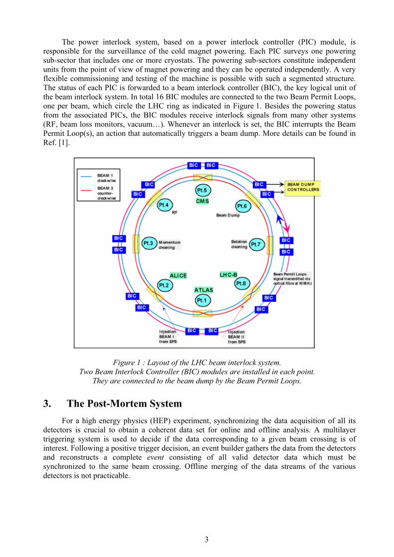
The power interlock system, based on a power interlock controller (PIC) module, is responsible for the surveillance of the cold magnet powering. Each PIC surveys one powering sub-sector that includes one or more cryostats. The powering sub-sectors constitute independent units from the point of view of magnet powering and they can be operated independently. A very flexible commissioning and testing of the machine is possible with such a segmented structure. The status of each PIC is forwarded to a beam interlock controller (BIC), the key logical unit of the beam interlock system. In total 16 BIC modules are connected to the two Beam Permit Loops, one per beam, which circle the LHC ring as indicated in Figure 1. Besides the powering status from the associated PICs, the BIC modules receive interlock signals from many other systems (RF, beam loss monitors, vacuum…). Whenever an interlock is set, the BIC interrupts the Beam Permit Loop(s), an action that automatically triggers a beam dump. More details can be found in Ref. [1].
Figure 1 : Layout of the LHC beam interlock system. Two Beam Interlock Controller (BIC) modules are installed in each point.
They are connected to the beam dump by the Beam Permit Loops.
3. The Post-Mortem System For a high energy physics (HEP) experiment, synchronizing the data acquisition of all its
detectors is crucial to obtain a coherent data set for online and offline analysis. A multilayer triggering system is used to decide if the data corresponding to a given beam crossing is of interest. Following a positive trigger decision, an event builder gathers the data from the detectors and reconstructs a complete event consisting of all valid detector data which must be synchronized to the same beam crossing. Offline merging of the data streams of the various detectors is not practicable.
3
The post-mortem event data set can be considered as the equivalent of a HEP event, the machine protection system playing the role of the HEP experiment trigger. The event data is the central item of the post-mortem system and corresponds to a snapshot of the LHC machine, from the point of view of the beam and equipment, during the transient period around a beam or power abort. Compared to a HEP experiment, there are some fundamental differences that complicate the LHC post-mortem event and have consequences on the design:
− The equipment systems are not localized around one interaction region, but are distributed over the entire ring. Synchronization of such a distributed system is complicated.
− The event data does not cover a single beam crossing or turn but must also hold the history of the ‘last’ moments before the abort.
− Many systems have an active role in the protection of the machine. − Severe incidents like power cuts must be handled.
The post-mortem system must collect data on beam parameters, LHC equipment status, interlocks, alarms, operator and feedback actions, etc. Precise time-stamping at the equipment level (i.e. the source of the data) is mandatory to reconstruct unambiguously the event history. To deliver data around an event that can occur any time, equipment systems must store their live data in a circular buffer with an adequate depth, the so-called post-mortem buffer. The buffer contents must be frozen by a post-mortem trigger that must reach every equipment in the ring within a very short time following an abort. This aspect is particularly important for measurements with high sampling rates (turn by turn or bunch by bunch). Finally the post-mortem data acquisition must gather the information from all sources and construct the complete event data set. Before beam or power operation can be resumed, the post-mortem acquisitions must be re-enabled and the post-mortem buffers un-frozen. For critical systems the ‘acquisition ready’ status could be included in the permit signal to interlock system, as is for example foreseen for the quench protection system.
It will be crucial for the LHC to guarantee a clean extraction of the beams in case of severe power cuts, situations that are delicate to handle. To diagnose a beam dump under such conditions implies that critical systems must be connected to Un-interrupted Power Supplies (UPS). This aspect requires a careful analysis in particular to understand the consequences of major networking problems to make sure that the most critical information (beam dump, beam losses) is not lost. The reliability and availability of the UPS systems must be very high.
4. The Post-mortem Buffer The circular post-mortem buffer is the key post-mortem element that must be implemented
by equipment systems. The buffer depth depends on the equipment and on the sampling rates. The contents of the buffer must be frozen by an external or internal (self-triggering) event. The possibility to read out the post-mortem buffer at any time should be foreseen wherever such a feature could add valuable diagnostics.
4.1. Buffer Depth
The time scales that lead to a beam loss or power abort span a few orders of magnitude [5], from only a few turns to a few seconds. Furthermore, following a quench of one of the main magnet circuits (dipoles, quadrupoles), the energy stored in the magnets will be extracted over a time interval of a few minutes after the power abort. Since monitoring the energy extraction is important to verify the good functioning of the quench protection system, these data must also be part of the post-mortem event.
4
Data delivered to the post-mortem system can be split into 2 main categories, high resolution (turn by turn, bunch by bunch, sampling interval of 1 ms or less) and low resolution. High resolution data should cover ~ 1000 samples before the trigger, which in general corresponds to an equivalent number of machine turns. For low resolution data, the time spanned by the post-mortem data should cover the last 20 to 30 seconds prior to the trigger and some time beyond it. Effects that build up over longer time scales are not considered to be ‘fast’ transients, they must therefore be reconstructed using the normal data logging.
4.2. Time-stamping
Precise time-stamping is mandatory to correlate data from different systems, or from different measurement devices of a given system. For measurements with high sampling rates (turn by turn or bunch by bunch), which concern mainly the beam instrumentation, beam dump, injection and RF systems, the accuracy of the time-stamping should be better than one turn (≤ 50 µsec). This requirement will be fulfilled by the date information transmitted through the general machine timing (GMT) system [6] and by dedicated GPS receivers.
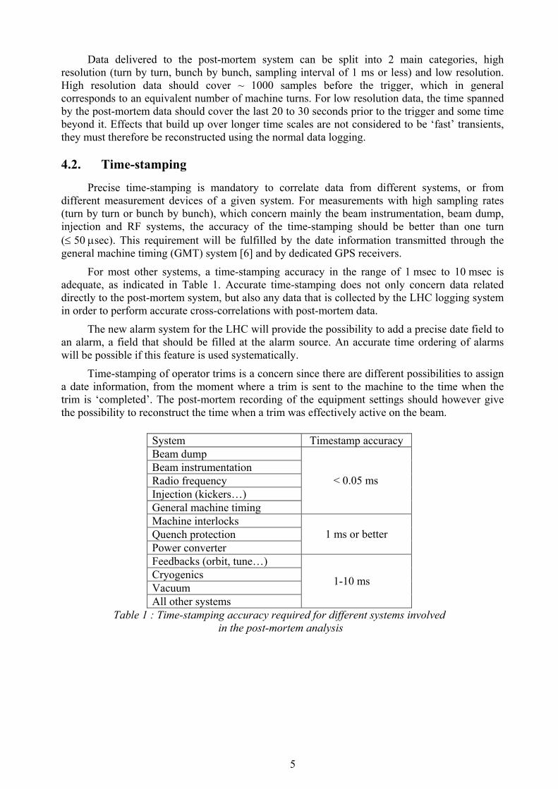
For most other systems, a time-stamping accuracy in the range of 1 msec to 10 msec is adequate, as indicated in Table 1. Accurate time-stamping does not only concern data related directly to the post-mortem system, but also any data that is collected by the LHC logging system in order to perform accurate cross-correlations with post-mortem data.
The new alarm system for the LHC will provide the possibility to add a precise date field to an alarm, a field that should be filled at the alarm source. An accurate time ordering of alarms will be possible if this feature is used systematically.
Time-stamping of operator trims is a concern since there are different possibilities to assign a date information, from the moment where a trim is sent to the machine to the time when the trim is ‘completed’. The post-mortem recording of the equipment settings should however give the possibility to reconstruct the time when a trim was effectively active on the beam.
System Timestamp accuracy Beam dump Beam instrumentation Radio frequency Injection (kickers…) General machine timing
< 0.05 ms
Machine interlocks Quench protection Power converter
1 ms or better
Feedbacks (orbit, tune…) Cryogenics Vacuum All other systems
1-10 ms
Table 1 : Time-stamping accuracy required for different systems involved in the post-mortem analysis
5

5. The Post-Mortem Trigger Ideally all systems involved in the LHC should be triggered by the post-mortem event in
case of a failure, but in reality the situation is more complex due to the involvement of many systems in the protection of the LHC machine, to slow sampling rates and to other design considerations. Therefore only a fraction of all equipment will require or accept the post-mortem trigger. The equipment systems involved in LHC operation can be split into two main categories from the point of view of post-mortem.
A first category includes systems that require or accept an external post-mortem trigger. The main systems in this category are
− beam instrumentation, − power converter system, − radio frequency system (including dampers and longitudinal feedbacks),
which will freeze their buffers on reception of the event, with a few recordings added beyond the post-mortem trigger event.
A second category involves systems providing a self-triggering mode. Such systems will automatically record post-mortem data, either continuously or whenever a fault condition is detected. Some of the systems are exclusively self-triggering, while others also provide external triggering. This category includes
− machine interlock system, − warm magnet surveillance system, − quench protection system (including energy extraction), − beam dumping system, − injection kicker system, − power converter system (in case of converter faults), − radio frequency system (including dampers and longitudinal feedbacks), − vacuum system (in case of valve closure).
The interlock system will provide a continuous logging of all state transitions that can be read out by the post-mortem system. The beam dumping system will automatically record all post-mortem data required for its internal diagnostics. The analysis of this data will be part of the procedure used to re-enable the beam dumping system for operation with beam. It is required to ensure the correct functioning of the beam extraction procedure and to detect abnormal operation of the dump system as soon as possible. A similar automatic analysis is also foreseen for the QPS system.
A certain number of systems are decoupled from the post-mortem event acquisition. Their information will be available through the logging, the alarm and the machine settings database, namely
− vacuum system (pressures), − cryogenic system, − LHC transfer lines (at injection), − general machine parameters (run numbers, optics name, filling pattern,…).
No particular post-mortem recording is required for those systems as long as those data are logged regularly with precise timestamps.
6
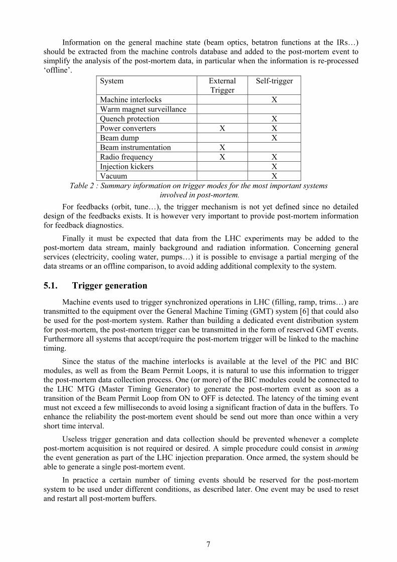
Information on the general machine state (beam optics, betatron functions at the IRs…) should be extracted from the machine controls database and added to the post-mortem event to simplify the analysis of the post-mortem data, in particular when the information is re-processed ‘offline’.
System External Trigger
Self-trigger
Machine interlocks X Warm magnet surveillance Quench protection X Power converters X X Beam dump X Beam instrumentation X Radio frequency X X Injection kickers X Vacuum X
Table 2 : Summary information on trigger modes for the most important systems involved in post-mortem.
For feedbacks (orbit, tune…), the trigger mechanism is not yet defined since no detailed design of the feedbacks exists. It is however very important to provide post-mortem information for feedback diagnostics.
Finally it must be expected that data from the LHC experiments may be added to the post-mortem data stream, mainly background and radiation information. Concerning general services (electricity, cooling water, pumps…) it is possible to envisage a partial merging of the data streams or an offline comparison, to avoid adding additional complexity to the system.
5.1. Trigger generation
Machine events used to trigger synchronized operations in LHC (filling, ramp, trims…) are transmitted to the equipment over the General Machine Timing (GMT) system [6] that could also be used for the post-mortem system. Rather than building a dedicated event distribution system for post-mortem, the post-mortem trigger can be transmitted in the form of reserved GMT events. Furthermore all systems that accept/require the post-mortem trigger will be linked to the machine timing.
Since the status of the machine interlocks is available at the level of the PIC and BIC modules, as well as from the Beam Permit Loops, it is natural to use this information to trigger the post-mortem data collection process. One (or more) of the BIC modules could be connected to the LHC MTG (Master Timing Generator) to generate the post-mortem event as soon as a transition of the Beam Permit Loop from ON to OFF is detected. The latency of the timing event must not exceed a few milliseconds to avoid losing a significant fraction of data in the buffers. To enhance the reliability the post-mortem event should be send out more than once within a very short time interval.
Useless trigger generation and data collection should be prevented whenever a complete post-mortem acquisition is not required or desired. A simple procedure could consist in arming the event generation as part of the LHC injection preparation. Once armed, the system should be able to generate a single post-mortem event.
In practice a certain number of timing events should be reserved for the post-mortem system to be used under different conditions, as described later. One event may be used to reset and restart all post-mortem buffers.
7

6. Post-mortem Operation Modes The operation of the post-mortem system can be split into three basic modes that require a
somewhat different treatment of the post-mortem trigger and data acquisition. The three modes are operation with beam, operation without beam and test mode.
6.1. Operation without beam
During commissioning of LHC sectors, cold-checkout periods and whenever no beam is allowed in the LHC, each powering sub-sector can be operated independently and constitutes an individual entity for the post-mortem system. A quench or a powering problem will affect a single powering sector, controlled by one Power Interlock Controller. Post-mortem data should only be collected for the corresponding sub-sector. The equipment systems that are involved are the quench protection, the power converter, the interlock, the cryogenic and the vacuum systems. Both power converter and quench protection systems will automatically generate post-mortem data for faulty channels, while the interlock system will record input and output state changes continuously. Information of the state of the cryogenics and the vacuum must be available through the LHC logging system.
Generation of a post-mortem trigger in this mode is complicated, since a different trigger event must be assigned to each of the 28 powering sub-sectors. On the other hand, if the post-mortem data collection is restricted to faulty channels, a post-mortem trigger is not required in this operation mode. It is sufficient to detect the state change of the PIC and to gather the post-mortem buffers that are generated automatically by the power converters and the quench protection system.
6.2. Operation with beam
Whenever beam is present in the LHC, a beam dump triggered by the machine interlock system must be followed by a complete post-mortem recording. To distinguish this mode from operation without beam, the post-mortem system must be armed during preparation for injection to enable the generation of the post-mortem trigger event. To avoid useless post-mortem recordings during operation without beam, the system should not be armed in the absence of beam.
Under most running conditions, both LHC beams will be dumped at the same time. This statement applies certainly to dumps that are triggered by the interlock system. Indeed a large number of faults affect both beams and it will not be possible to determine which beam must be dumped with sufficient reliability in the short time available to take a decision. Nevertheless, the Beam Permit Loops and beam dumps being independent for the two rings, a selective dump is possible for each ring,
6.2.1. Operator triggered dumps A selective dump of the beam in one ring will certainly be required at injection when the
parameters of one beam are not adequate (intensity, emittance…), for example after a bad transfer. Rather than dumping both beams to restart injection from scratch, it is more efficient to dump only the beam with incorrect parameters and refill the corresponding ring. For a clean beam dump no post-mortem information is a priori needed, with the exception of the beam dumping system (of the corresponding ring) where the post-mortem data is always required for internal dump diagnostics. It is therefore proposed not to trigger a general post-mortem recording when a single beam is dumped by an operator, to avoid freezing buffers while one beam is still present in the machine.
8
If as a consequence of the dump, the remaining beam becomes unstable and must be also be dumped, the post-mortem buffers should cover the complete event sequence including both dumps. In such a situation the time between the two dumps is likely to be very short (~ seconds or less) and the post-mortem buffer depth of ~ 20 seconds should be adequate. Operational experience of the LHC will eventually determine whether dumping one out of the 2 beams is possible or not.
When an operator dumps both beams, a complete post-mortem recording should be a priori foreseen, at least for operation above injection energy. The possibility to restrict the data collection to a subset of the full data set (including for example only beam instrumentation) should be foreseen for dumps triggered by operators, at least at injection when frequent dumps and refills may be required for machine and transfer line tuning.
6.3. Test mode
The post-mortem system must be tested with beam in the machine, and, since a test implies freezing the buffers in most systems, no post-mortem recording will be possible for a certain time interval after the test. For safety reasons, the beam dump and all other active protection systems must be excluded from the test which must only be allowed with low intensity beams. The intensity should be well below damage threshold, i.e. corresponding to a window around the pilot bunch intensity of 5 × 10⁹ to few 1010 protons in the machine (at injection).
7. The Post-mortem Data Acquisition This section is devoted to some aspects of the data acquisition and to the event structure.
The overall organization of the post-mortem data must be rigid in terms of data encoding formats, but at the same time, the event structure must be open for additions of data at any time (to accommodate new channels, analysis results to be appended to the data stream…).
7.1. Data Format
The diversity of acquisition systems involved in the LHC requires a coherent and self-describing format for port-mortem data. To avoid problems with multiple encoding algorithms, all data could be stored and transmitted in ASCII format with self-describing header information. The data volumes can be reduced at a later stage by file compression and after data analysis. The format could be based on XML (eXtensible Markup Language), a wide spread standard format for ASCII data. Alternatively it could be envisaged to provide a standard encoding software for binary data formats. More details on the proposed data structure are given in Appendix A.
7.2. Data Collection
Construction of the post-mortem event involves the collection and re-combination of all data in the form of a logical event data set. To simplify the collection process, systems that are triggered (and therefore know that their data will be requested) should forward their data automatically to central fileservers where it must be stored in a well-defined location. Such a scenario has the advantage of simplifying the data collection. This option cannot be applied to un-triggered systems (interlocks) and a certain number of servers must be operated to collect these data. Finally it will always be necessary to verify the completeness of the event and a database holding the complete list of measurement/equipment devices will be required for a verification procedure.
9

A certain number of central servers may be required to manage data collection and event re-construction from the individual pieces. Constant monitoring of the interlock state of the LHC is required to trigger the correct actions, including the analysis of the data.
7.3. Event Number
During the data collection process, a unique event number must be assigned to a given post-mortem event. This event number could be sent out together with the trigger such that all externally triggered systems could add this information to the data stream to ease the processing.
8. Data Analysis and Display A large amount of data (a few Gb) will be recorded for every trigger during operation with
beam. Manual browsing and viewing of selected data items must be possible, but an automated online data reduction and analysis must be performed for each event. This online analysis must assist the operation crews in understanding the cause of failure and the state of the machine. It must be possible to rerun the analysis programs offline, in particular to refine the analysis for events with a complex sequence of failures.
The primary task of the online analysis consists in generating an overall view of the machine in terms of interlocks and faulty elements. This will allow the operations crews to know which elements are in fault and which interlock channel triggered the beam. This first level analysis should be available within less than a minute in the control room. On a time scale of a few minutes, more refined analysis tasks can be performed: summary information on the evolution of the orbit, the beam losses (location and rates), beam currents, power converters… must be provided. The post-mortem analysis should be able to detect simple abnormal conditions (orbit, beam losses, quenches…) and direct this information to the operators who cannot start a random search though the huge amount of information that is gathered by the post-mortem system. Since the analysis of complex equipment like RF, dampers, feedbacks… is delicate, the corresponding software must be developed by or in close collaboration with the equipment experts. Assistance of equipment experts may be required to understand certain failures. The analysis of post-mortem data will clearly evolve substantially as more experience is gained over the years. As a general rule all the software components should be modular and be easy to integrate and activate.
Tags or selection flags, set by the analysis software, should be defined and stored together with each post-mortem event to categorize it for later analysis and machine statistics. A simple selection of post-mortem events must be possible from the flags according to the systems that triggered the abort, the beam conditions… This concept is similar to the trigger flags and data streams used in HEP experiments to classify events by trigger conditions and physics process.
The analysis software of the post-mortem event should generate a compressed post-mortem data set holding all the key information relevant for the event (faulty elements, evolution of main beam parameters, machine conditions, selection flags…). Such processed information can be accessed quickly without re-processing the data. Information relevant for INB regulations (dumped beam intensity, dump quality, …) must also be included in the compressed set. It must be possible to re-generate the compressed data set by re-analysing the post-mortem raw data, in particularly when new versions of the analysis program become available.
Finally a very compact summary data set may be generated for each event. Such a summary set should contain information relevant for INB, data on the beam and machine conditions at the time of the abort and a description of the event sequence.
10
8.1. Equipment Naming Conventions and Databases
To simplify cross-correlation of data from different equipment, a precise naming convention must be enforced. The complete equipment lists must be available in the LHC controls database. To simplify correlation analysis between sensors and actuators from different systems, the longitudinal position must be available for each component/device and stored in the same database. Very simple algorithms can then be used to determine the distance in space between different equipment channels, a very useful feature for cross-comparisons.
9. Data storage For LEP logged data was stored in ORACLE database tables and flat files, the later being
organized by run (fill) numbers. A similar approach is used at the SPS. The size of the post-mortem raw data might be too large to be suitable for storage in an ORACLE database. At the same time the volumes are too large to be stored in a single file. Storage in a number of separate files, organized by equipment type in a directory structure may be a possible approach which would make the system flexible for modifications. File paths dedicated to the analysis results might be defined to separate raw and processed data.
A large amount of disk space (several 100 Gb) must be available to store the latest post-mortem events. Sufficient space must be provided to hold compressed information for an entire run. It is proposed to provide fast access over the following time spans:
− Raw data ~ 2-4 weeks (all events) − Raw data ~ 1 run (for difficult/unexplained events) − Compressed data few years − Summary data lifetime of the LHC
To cope with the large data volumes and provide the possibility of re-processing past events, long-term storage on a tape medium (see Ref. [7] and Appendix B) or equivalent should be considered, at least if this provides an economically interesting option. Ideally all raw data should be archived for the lifetime of the LHC, as is current practice in HEP experiments.
An important aspect of the storage is the ‘integrity’ of the post-mortem event: it must be possible to handle all the data of a given post-mortem event through one operation in particular when the data is moved to or retrieved from backup (long term) storage.
10. The Post-mortem and Logging Systems The LHC post-mortem and logging system must be able to ‘interact’ since some data will
only be available through the logging system. In addition, both systems require tools to visualize data (evolution, correlation). Furthermore both systems require large amounts of storage space. Common solutions could be adopted wherever possible or reasonable. Data access and visualization should be transparent for both systems, i.e. rely on common interfaces that automatically route to the appropriate data source.
11. Conclusions First design ideas and requirements for the LHC post-mortem have been presented and
some guidelines for the realization of this system have been given. We consider that this system is mandatory for operation of the LHC as shown for example by the experience at HERA [8]. A first version of this system will be required during the LHC sector commissioning in 2005.
11
Significant experience can be gained during the successive commissioning of all LHC sectors, reducing the burden when operation with beam will start.
The main requirements and components of the post-mortem system are:
− Circular, reserved data buffers that must be implemented at the equipment level, − Freezing of the buffers by an internal or external trigger, − Precise time-stamping with accuracies ranging from few µseconds to 10 milliseconds, − A data collection system, − Modular analysis and display software, − A coherent and unique equipment naming convention, − Large volumes of data storage.
The design presented here is concentrated on the LHC and the systems that are considered to be close to the machine. General services have not been considered so far, but the integration of their post-mortem system should be considered, at least to a level where a simple cross-analysis becomes possible.
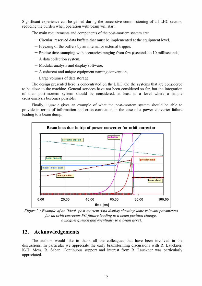
Finally, Figure 2 gives an example of what the post-mortem system should be able to provide in terms of information and cross-correlation in the case of a power converter failure leading to a beam dump.
Figure 2 : Example of an ‘ideal’ post-mortem data display showing some relevant parameters
for an orbit corrector PC failure leading to a beam position change, a magnet quench and eventually to a beam abort.
12. Acknowledgements The authors would like to thank all the colleagues that have been involved in the
discussions. In particular we appreciate the early brainstorming discussions with R. Lauckner, K-H. Mess, R. Saban. Continuous support and interest from R. Lauckner was particularly appreciated.
12

13. References 1. F. Bordry et al, Machine Protection for the LHC: architecture of the beam and powering
interlock systems, LHC Project Report 521, December 2001. 2. L. Arnaudon et al, RF trip and Beam Loss Diagnostics in LEP using GPS Timing,
CERN-SL-2000-055 LRF. 3. L. Arnaudon et al., LEP RF trip and Beam Loss Diagnostics, Proc. EPAC 2002, Paris. 4. R.Lauckner, What data is required to understand failures during LHC operation,
LHC Workshop, CHAMONIX 11, 2001, CERN-SL-2001-003-DI. 5. O.Brüning, Mechanisms for beam losses and their time constants, LHC Workshop,
CHAMONIX 11, 2001, CERN-SL-2001-003-DI. 6. LHC Timing Working Group, The CERN Machine Timing System for the LHC Era,
Eng. specification LHC-C-ES-0004 v2.0, EDMS # 329670. 7. CASTOR project, http://wwwinfo.cern.ch/pdp/castor/ . 8. M. Lomperski, Experience with the proton beam loss monitoring system at HERA,
LHC Workshop, CHAMONIX 11, 2001, CERN-SL-2001-003-DI.
14. Appendix A : Data format The proposed data format should include a self-describing data header. The data should
include :
− Instrument/equipment name − Post-mortem event number (if available) − Time Base information
− Trigger Timestamp (if accepted) or reference Timestamp T0 − Channel number @ T0 − Time increment / interval
− Channel 1 data − Name − Column 1 header
− SI Units − Decade of units (optional, default = 1) − Calibration information (optional)
− Polynomial − Column 2 header − … − Column m header − Actual data
− Data entry 1 (columns 1 to m) − Data entry 2 (columns 1 to m) − … − Data entry N (columns 1 to m)
− Channel 2 data − … − Channel n data
13
For event tables containing state transitions, the actual data entries will have to include a timestamp as well as the new state. For each channel more than one data item may be returned.
15. Appendix B : the CASTOR project for tape storage To cope with the large data volumes and provide the possibility of re-processing past
events, long-term storage on a tape medium could be considered
In this respect the post-mortem system can profit from the developments made for the LHC experiments and from the infrastructure provided by the CERN-IT division. CASTOR [7] (CERN Advanced STORage manager), the present CERN storage management system, is a disk pool manager coupled with tape storage, the data being accessed over disk cache. The goal of CASTOR is to handle LHC data in a fully distributed environment. Its main objectives are high performance, good scalability and easiness of deployment and support for thousands of future clients. It should be available on major UNIX systems as well as Windows/NT.
Within CASTOR the user data is referenced through a logical name space similar to a traditional file system rather than through explicit tape volume IDs and file sequences. CASTOR provides means for sensible naming and data organization of data on tape. In fact tape handling is totally transparent to the user and the data is accessed exactly like any other file through simple APIs. CASTOR has been stress tested by the ‘ALICE data challenge’. The required data rates are 100 MB/s for one week (60 TB of total tape storage), well beyond what is required for the LHC machine and post-mortem system.
To handle the post-mortem event storage, a pool of tapes reserved for the LHC machine could therefore be purchased and stored centrally at CERN. Storage of and access to the data should be done with CASTOR or whatever successor is provided by CERN-IT.
16. Appendix C : LHC equipment systems and post-mortem This appendix provides some additional details for post-mortem recording of a number of
equipment systems.
16.1. Beam instrumentation
The key beam instruments for post-mortem diagnostics in the LHC include:
− Beam position monitors, − Beam loss monitors, − Beam current transformers, − Non-destructive beam profile monitors (longitudinal and transverse), − Tune measurements, − Abort gap monitors.
Special instruments that require complex setups and that are not part of the baseline instrumentation for regular operation are not required to deliver post-mortem data.
For all beam instrumentation involved in post-mortem, turn by turn (or highest time resolution) data should be provided for all systems for the equivalent of 1000 turns (~ 80-100 ms) before the post-mortem trigger. Coarser data (for example averages over samples, closed orbits…) should be provided for the time interval of ~ 20-30 seconds before the trigger. Between 100 and 250 points should give an adequate sampling of that period. 10 to 20 samples should be provided after the trigger.
14

All beam instrumentation will require an external trigger to freeze the post-mortem buffers. The trigger will be transmitted over the BST system.
16.2. Quench protection system
The quench protection system provides data on quenches and on energy extraction. It will be entirely self-triggering. Upon request it will return the post-mortem data buffer for the quenched magnets. A maximum sampling rate of 100 Hz has been defined for all signals. For all other un-quenched magnets, it will only be possible to acquire a snapshot of the state. No external triggers will be accepted.
For QPS the ‘acquisition ready’ status will be included in the power permit signal to the power interlock controller.
The QPS system will have two levels of information: diagnostics for operation and a more detailed expert level of recordings.
16.3. Machine interlock system
The machine interlock system will provide a continuous logging of all the input state changes to the Power and Beam Interlock Controller modules. The data from the rolling buffer can be read out any time. The buffers will never be frozen since the system must be alive at any time.
16.4. Power converter system
The components of this system include all LHC machine magnet power converters, the LHC detector power converters (solenoids and spectrometer magnets) as well as the RF power converters. State, interlocks, faults and warnings, settings (real-time and table input) and DCCT readings will be provided for each power converter. The first four items will be returned as an event driven table. For the settings and DCCT values, a sampling rate of 10-100 Hz is sufficient for cold magnets. For warm magnets, due to the very short time constants, a sampling rate of 1 kHz is more adequate.
16.5. Beam dump system
The correct functioning of the LHC beam dump is critical for the safety of the machine. A post-mortem analysis must be performed for each dump on all recorded data to ensure that the beam dump was properly executed. The basic beam dump post-mortem information relies on the acquisition of signals covering 2 to 3 consecutive LHC turns with resolution and synchronization better than 100 ns. The post-mortem data set for the dump can be split in two different levels, an operator and an equipment (specialist) level. At the operator level, the main interest is to determine what happened to the beam, i.e. whether it was correctly send to the dump. At the equipment level, the post-mortem gives information on how the different sub-systems performed. Archiving of the post-mortem data is very important to detect long-term degradations.
In addition to the internal beam dump system information, the post-mortem data required for the analysis of a dump must also include:
− beam instrumentation data of the LHC dump extraction lines, − power converter data for the extraction septa and for the Q4 quadrupoles in IR6, − beam instrumentation data for instruments between the two Q4 quadrupoles on the
left and right side of IR6.
15

The recording and the triggering of those data may imply some special treatment, in particular when a single beam is dumped, see Section 6.
16.6. RF system
The RF system will generate large amounts of turn-by-turn and bunch-by-bunch data for some of its sub-systems. This includes data for longitudinal and transverse feedback. Automatic generation of post-mortem data in case of failures is foreseen in addition to external triggering.
16.7. Real-time Feedbacks
Orbit and tune feedbacks will be running continuously in the LHC. Each feedback system should provide post-mortem information on sensors and actuators. Such information will anyhow be required for feedback commissioning.
16.8. LHC Transfer Lines For the LHC transfer lines, the transfer data must be recorded for each injection.
The most important pieces of beam related information are the trajectory, the beam intensities and the beam losses. The settings and currents in each power converter are also of interest.
16.9. Warm Magnet Surveillance
The warm magnet surveillance system will be based on an interlock controller with functionalities that are similar to the BIC and PIC modules. A post-mortem recording of the input and output states will be required.
16.10. Reference Magnet System
The reference magnet system will provide information on magnet multi-poles. It will be used mainly at injection to predict settings for the correction circuits for various multi-poles. The recording frequency will be of the order of a few Hz. Post-mortem information for this data will be particularly important during injection and in the first part of the ramp.
16.11. Collimators and protection devices
The positions of all collimators and al movable protection devices (for injection and around the beam dump channel in IR6) must be recorded.
16.12. Alarm system
The alarm system operates independently of the LHC machine interlock and post-mortem systems. The information contained in the sequence of alarms is useful for the analysis of a beam or power abort. A precise time-stamping of each alarm at the source will provide the most reliable reconstruction of the alarm sequence.
16.13. Cryogenic system
The cryogenics system operates independently from the post-mortem system. It does not accept post-mortem triggers but relevant data can be obtained and transferred from the logging database. The basic recording frequency is 1 Hz. No fast transient recordings are foreseen.
16

17
16.14. Vacuum system
The vacuum system has not foreseen any external triggering. The pressures are scanned at 3 Hz and recorded on epsilon-changes. The valve status is scanned every few ms and state changes (open, moving, closed) are recorded and time-stamped. The data will be available from the equipment or from the logging system.
16.15. LHC Timing system
As part of the control system, the LHC timing system should provide a logging of all timing events that are send out.