post tender addendum no. 01...smithers regional airport, terminal upgrade and expansion smithers, bc...
TRANSCRIPT

POST TENDER ADDENDUM No. 01
Smithers Regional Airport
Terminal Upgrade and Expansion
Smithers, BC Contract 2017-11
July 19th, 2017 MW #16-181
Tom Moore, Architect AIBC, NCARB, B. Arch., Principal
Carolynn Wilson, Architect AIBC, M.Arch., B.Tech, LEED A.P., Principal
Moore Wilson Architects
531 Herald Street
Victoria, British Columbia
V8W 1S5
p. 250 384 2131
w. moorewilson.ca
The following addendum supplements and/or supersedes information contained in drawings and specifications issued for the
project to the extent referenced. The cost of all contained herein is to be included in the contract sum. This Addendum forms part
of the Tender Documents and is subject to all of the conditions set out in the contract conditions. All bidders are to acknowledge
receipt and acceptance of this addendum by indicating Addendum number and date on the Tender Form provided.
TABLE OF CONTENTS – Post Tender Addendum No. 01
1. Cover 1 page
2. Architectural Post Tender Addendum No. 01 4 pages
3. Sheet A1.01 – SITE PLAN 1 page
4. Drawing 1/A1.02 – PHASE 1 1 page
5. Drawing 1a/A1.02 – PHASE 1 TEMP. BOARDING LOUNGE PLAN 1 page
6. Drawing 6/A5.11 – SECTION @ BOARDING LOUNGE ROOF and
Drawing 7/A5.11 – SECTION @ BOARDING LOUNGE CANOPY 1 page
7. Drawing W06/A8.01 1 page
8. Mechanical Post tender Addendum No. 01 39 pages
9. Sheet M002 1 page
10. Sheet M102 1 page
11. Sheet M202 1 page
12. Sheet M211 1 page
13. Sheet M212 1 page
14. Sheet M213 1 page
15. Sheet M400 1 page
16. Sheet M401 1 page
17. Electrical Post tender Addendum No. 01 1 page
18. Civil Post Tender Addendum No. 01 1 page
19. Sheet C2 – SITE PLAN 1 page
20. Vector Projects Group – Project Cost Reduction Options 1 page
END OF Post Tender Addendum No. 01

ARCHITECTURAL POST TENDER
ADDENDUM No. 01
Smithers Regional Airport
Terminal Upgrade and Expansion
Smithers, BC
July 19th, 2017
Tom Moore, Architect AIBC, NCARB, B. Arch., Principal
Carolynn Wilson, Architect AIBC, M.Arch., B.Tech, LEED A.P., Principal
Moore Wilson Architects
531 Herald Street
Victoria, British Columbia
V8W 1S5
p. 250 384 2131
w. moorewilson.ca
ARCHITECTURAL POST TENDER ADDENDUM No. 01
Smithers Regional Airport, Terminal Upgrade and Expansion
Smithers, BC
MW Project No. 16-181 Date Issued: JULY 19, 2017
The following addendum supplements and/or supersedes information contained in drawings and specifications issued for the
project to the extent referenced. The cost of all contained herein is to be included in the contract sum. This Addendum forms part
of the Tender Documents and is subject to all of the conditions set out in the contract conditions. All bidders are to acknowledge
receipt and acceptance of this addendum by indicating Addendum number and date on the Tender Form provided.
1. GENERAL
.1 ADDENDUM #1 (VPG #SP2-1, #SP2-2 and #SP2-3)
1. Delete specification Section 08 44 33 – SLOPED GLAZING
2. Sheet A2.01 – LEVEL 1 PLAN delete windows W14, W15, W16, W17, W18, W19, W20, W21, W22 &
W23. Existing to remain.
3. Sheet A2.01 – LEVEL 1 PLAN delete new sloped glazing indicated on Sheet A2.01 – LEVEL 1 PLAN
near grid ‘1’ between ‘E’ and ‘F’. Existing to remain
4. Sheet A4.02 – SECTION @ ARRIVALS revise canopy roof structure from CLT to NLT
2. SPECIFICATIONS
.1 SECTION 00 15 00 – 00800 SUPPLEMENTARY CONDITIONS (VPG #1) – Paragraph 1.10 INSURANCE
CONDITIONS:
1. Add the following sentence:
1.11 The Town will provide Wrapup Liability Insurance with a limit of $10,000,000 which
includes the Owner, contractor, subcontractors, project and construction
managers, architects, engineers and consultants whilst engaged in operations
related to the project.
.2 SECTION 01 52 00 – CONSTRUCTION FACILITIES (VPG #4) – Paragraph 1.2 FIELD OFFICES:
1. Revise Sentence 1.2.4.1 to read:
The agreed upon building to the north side of the parking lot will be provided as a site
office for the Contractor’s use, the Contractor is responsible for equipment and sevices
to the building.
.3 SECTION 01 73 50 – ENVIRONMENTAL PROTECTION (VPG #3) – Paragraph 1.9 FILL QUALITY:
1. Add the following sentence:
3. Clean fill, soil, concrete and asphalt excavated from the construction areas can
shall be placed on site as directed by the owner.
Tom Moore, Architect AIBC, NCARB, B. Arch., Principal
Carolynn Wilson, Architect AIBC, M.Arch., B.Tech, LEED A.P., Principal
.4 SECTION 06 15 43 – CROSS LAMINATED TIMBERS (VPG #9) – Paragraph 2.02 MATERIALS:
1. Revise Sentence 2. from:
Douglas Fir appearance grade
To:
SPF appearance grade
.5 SECTION 07 42 13 – METAL WALL PANELS (VPG #20) – Paragraph 2.1 WALL PANEL TYPE 1:
1. Add the following sentence:
5. CAD layout plans to be provided
.6 SECTION 07 42 13 – METAL WALL PANELS (VPG #21 and #SP2-1) – Paragraph 2.5 MATERIALS:
1. Add the following sentence:
6. Insulation shall be Type 4 Extruded Polystyrene or Glass Faced Poly ISO in thickness
required to provide R/RSI values as indicated on drawings
.7 SECTION 07 44 00 – ALUMINUM MODULAR PANELS (VPG #22, #24 and #SP2-1) – Paragraph 2.1.1
Acceptable Systems:
1. Add Parker Johnston Composite Panel System
.8 SECTION 08 44 13 – GLAZED ALUMINUM SYSTEMS (VPG #14) – Paragraph 2.1.4. Alternate Systems:
1. Add the following sentence:
2. US Aluminum Clear Anodized Series 2200 Curtain Wall with 50mm (2”) face and
100mm (4”) back frame, US Aluminum Series 400T Medium Stile Doors and US
Aluminum Series IT451 Clear Anodized Storefront is acceptable if meeting the
performance standards as set out in Paragraph 1.4 in this Section
.9 SECTION 09 21 16 – GYPSUM BOARD ASSEMBLIES (VPG #19) – Paragraph 1.8:
1. Add the following sentence:
4. Only one (1) final third party inspection agency inspection need be provided.
.10 SECTION 12 49 20 – MOTORIZED ROLLER SHADES (VPG #7)
1. Delete entire section
3. DRAWINGS
.1 SHEET A0.03 (VPG #8, #25 and #SP2-2) – ROOF ASSEMBLIES:
1. Revise R1 from:
STANDING SEAM PRE-FINISHED METAL ROOF C/W CLIP SYSTEM
SELF ADHERED MODIFIED BITUMANOUS UNDERLAY C/W ICE DAM
12mm PLYWOOD SHEATHING
175mm RIGID INSULATION (R40-R40 EF.)
MULTIPLY CLT (SLOPED) C/W DOUBLE CAULK SEAL BETWEEN PANELS (MIN.R8-R8 EF.)
To:
STANDING SEAM PRE-FINISHED METAL ROOF C/W CLIP SYSTEM
2 LAYERS OF 90mm RIGID INSULATION (R40-R40 EF.)
18GA. 180mm GALV. Z CLIPS AT 610mm OC PERPENDICULAR TO ROOF SLOPE
SELF ADHERED MODIFIED BITUMINOUS UNDERLAY C/W ICE DAM
NLT PANEL (SLOPED) C/W DOUBLE CAULK SEAL BETWEEN PANELS (MIN.R8-R8 EF.)
2. Revise R2 from:
PVC ROOFING MEMBRANE
12mm PLYWOOD UNDERLAY
175mm RIGID INSULATION (R40-R40 EF.)
MULTIPLY CLT (SLOPED) C/W DOUBLE CAULK SEAL BETWEEN PANELS (MIN.R8-R8 EF.)
To:

Tom Moore, Architect AIBC, NCARB, B. Arch., Principal
Carolynn Wilson, Architect AIBC, M.Arch., B.Tech, LEED A.P., Principal
PVC ROOFING MEMBRANE
12mm PLYWOOD UNDERLAY
2 LAYERS OF 90mm RIGID INSULATION (R40-R40 EF.)
SELF ADHERED MODIFIED BITUMANOUS UNDERLAY
NLT PANEL (SLOPED) C/W DOUBLE CAULK SEAL BETWEEN PANELS (MIN.R8-R8 EF.)
3. Revise R3 from:
PVC ROOFING MEMBRANE
MULTIPLY CLT (SLOPED)
To:
PVC ROOFING MEMBRANE
NLT PANEL (SLOPED)
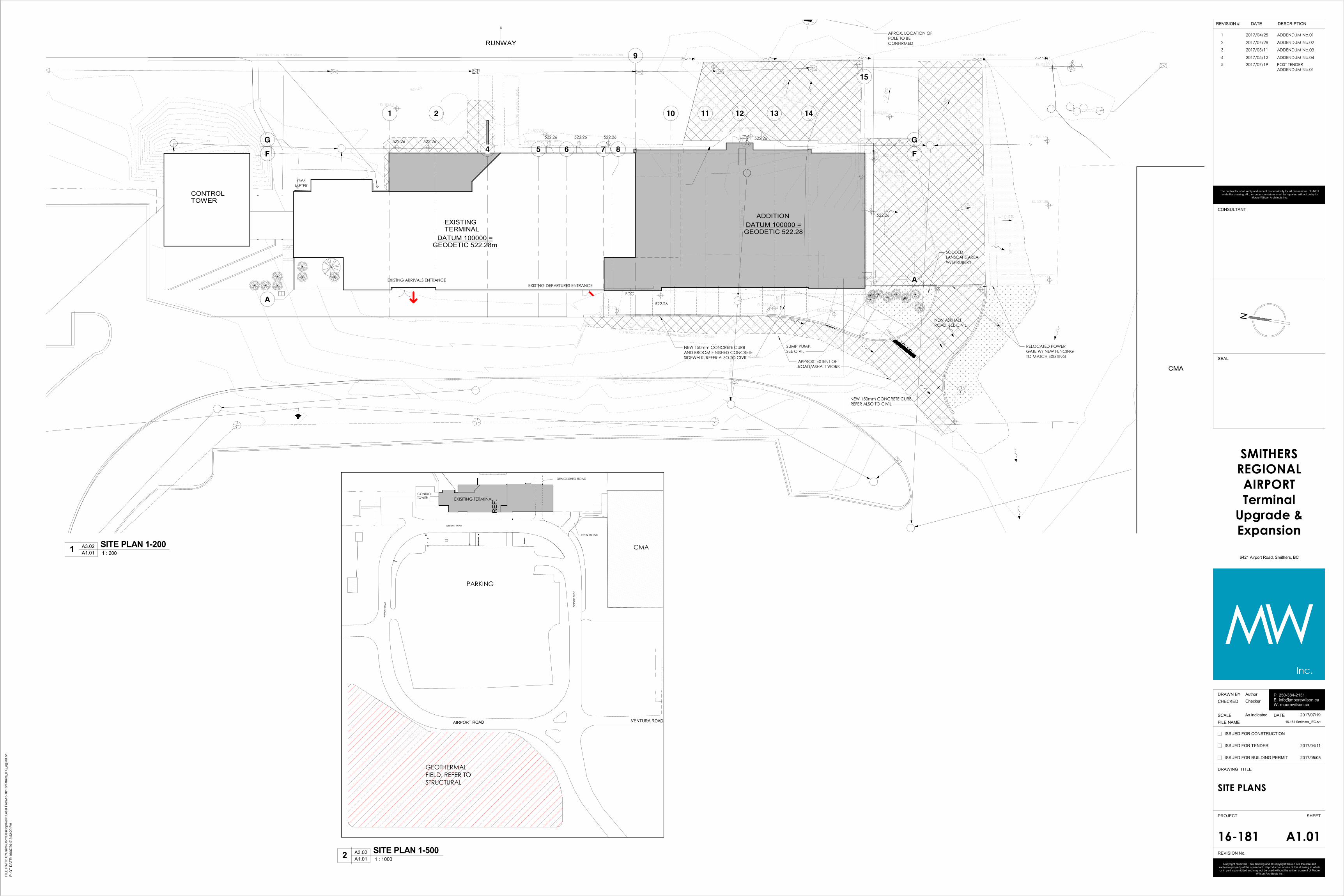
.2 SHEET A1.01 (VPG #6) – SITE PLAN:
1. Replace sheet A1.01 - SITE PLAN with attached.
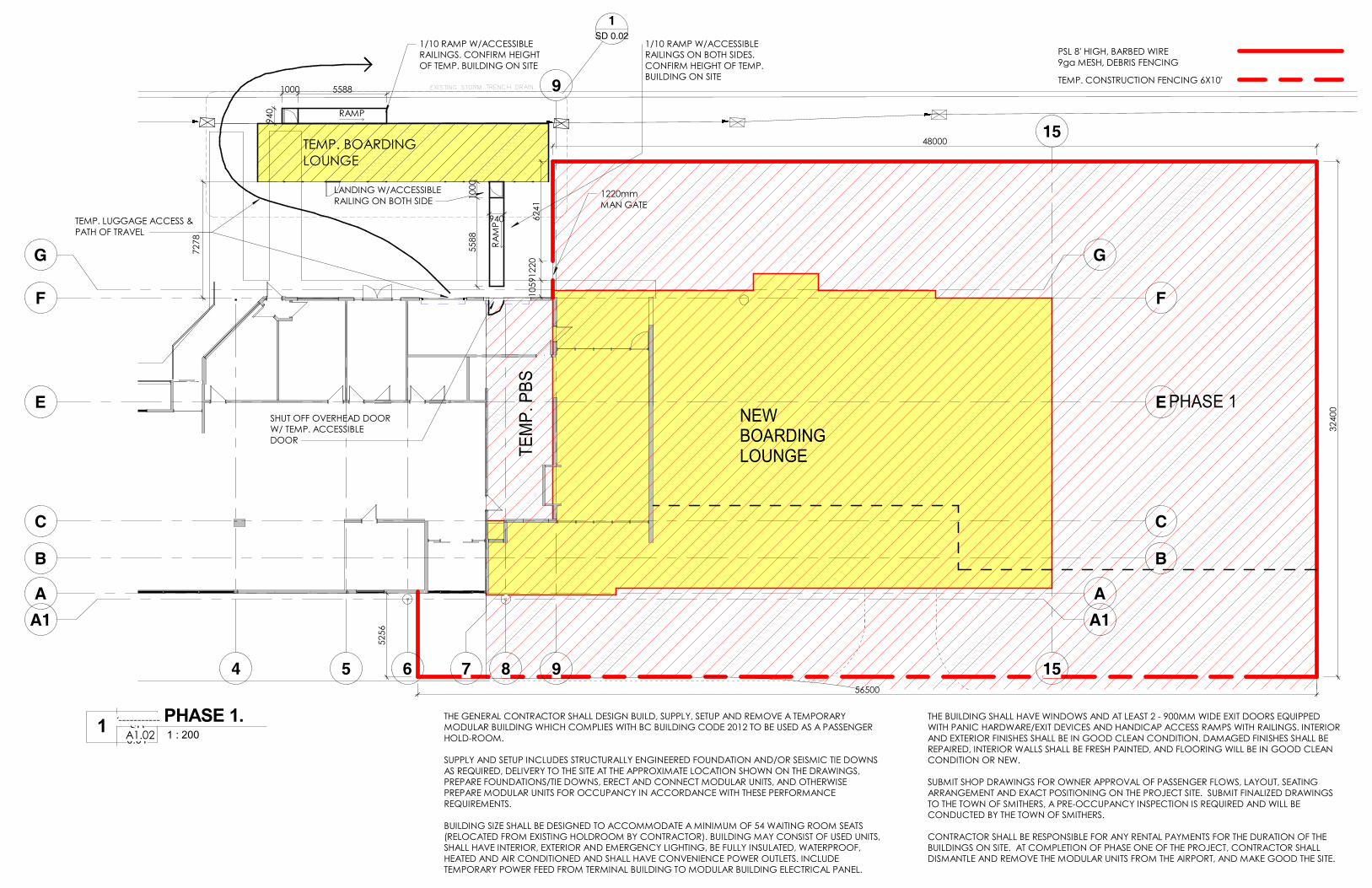
.3 SHEET A1.02 (VPG #5) – PHASING PLANS:
1. Revise drawing 1/A1.02 with attached
2. Add drawing 1a/A1.02 as attached
.4 SHEET A2.01and A2.02 (VPG #18) – FINISHES LEGEND:
1. Revise Item #3 under walls from:
TILE TO U/S OF CEILING
To:
TILE TO 1800mm AFF DADO
.5 SHEET A2.02 (VPG #11 and #13) – LEVEL 1 PLAN:
1. Delete the NEW DISPLAY cabinet at gridline 4 between gridlines C and E
2. Delete the check-in counter near gridline E between gridlines 4 and 5
.6 SHEET A2.03 (VPG #8) – ROOF PLAN:
1. Revise the canopy dimension near gridline A and 15 from 1850 to 1550
.7 SHEET A3.01and 32.02 (VPG #23 and #SP2-1) – MATERIAL LEGEND:
1. Revise Item #5 from:
ANODIZED ALUMINUM PANEL
To:
PRE-FINISHED ‘BRIGHT SILVER’ PANEL
.8 SHEET A5.01 (VPG #23 and #SP2-1) – Details 3, 5, 6 and 8:
1. Revise note from:
CLEAR ANOD. ALUMINUM BREAK SHAPE TO MATCH FASCIA BONDED TO 19MM
PLYWOOD
To:
PRE-FINISHED COMPOSITE METAL PANEL TO MATCH FASCIA
2. Delete 19mm plywood from detail relating to this panel
.9 SHEET A5.02 (VPG #16) – Details 3 and 4:
1. Delete steel column shown in curtain wall frame.
2. Delete note:
HEAVY GUAGE CLEAR ANOD. ALUM CAP OVER STEEL COLUMN, CAP DIMENSIONS
TO MATCH CURTAIN WALL BACK FRAME
.10 SHEET A5.11 (VPG #8, #23 and #SP2-1) – Details 1, 3, 6 and 9:
1. Revise note from:

Tom Moore, Architect AIBC, NCARB, B. Arch., Principal
Carolynn Wilson, Architect AIBC, M.Arch., B.Tech, LEED A.P., Principal
CLEAR ANOD. ALUMINUM BREAK FASCIA BONDED TO 19MM PLYWOOD AND
MOUNTED…
To:
PRE-FINISHED COMPOSITE METAL PANEL TO MATCH MOUNTED…
2. Delete 19mm plywood from detail relating to this panel
3. Replace all references to‘CLT’ with ‘NLT’
.11 SHEET A5.11 (VPG #8) – Details 6 and 7:
1. Replace details with attached.
.12 SHEET A5.11 (VPG #16) – Detail 8:
1. Delete steel support shown in curtain wall frame.
2. Delete note:
HEAVY GUAGE CLEAR ANOD. ALUM CAP OVER STEEL COLUMN, CAP DIMENSIONS
TO MATCH CURTAIN WALL BACK FRAME
3. Revise note from:
CURTAIN WALL VENEER PROFILE MOUNTED TO STEEL SUPPORT GRID, REFER TO
STRUCTURAL
To:
CURTAIN WALL SYSTEM, REFER TO ELEVATIONS
.13 SHEET A5.12 (VPG #8, #23 and #SP2-1) – Detail 2:
1. Revise note from:
CLEAR ANOD. ALUMINUM BREAK FASCIA BONDED TO 19MM PLYWOOD AND
MOUNTED…
To:
PRE-FINISHED COMPOSITE METAL PANEL TO MATCH MOUNTED…
2. Delete 19mm plywood from detail relating to this panel
3. Replace all references to‘CLT’ with ‘NLT’
.14 SHEET A7.01 (VPG #11 and #12) – Details 1, 6 and 7:
1. 1/A7.01 Delete the check-in counter to the left of gridline 5
2. 6&7/A7.01 Delete the solid surface wall treatment
3. 6&7/A7.01 Delete note ‘SOLID SURFACE TYPE #2’
.15 SHEET A7.02 (VPG #8) – CLT WALL & ROOF ELEVATIONS AND PLANS:
1. Revise the canopy dimensions off gridline A from 1821 to 1521
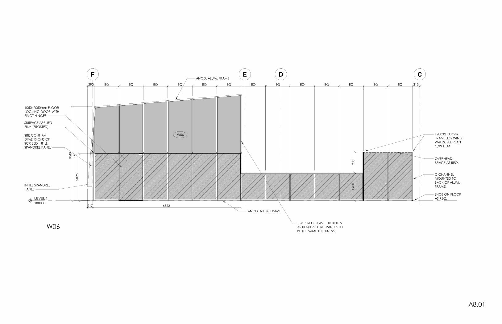
.16 SHEET A8.01 (VPG #15) – Details/Window W06:
3. Replace detail/window W06 with attached.
.17 SHEET A9.01 (VPG #10) – Detail C3.1 and C4.1:
1. Revise note from:
6.5mm SOLID SURFACE TYPE #1 ON 19mm ARCHITECTURAL GRADE PLYWOOD
To:
P.LAM TYPE 1 ON 19mm PLYWOOD
2. Revise note from:
RESIN GLAZING PANEL
To:
P.LAM TYPE 2 ON 19mm PLYWOOD
.18 SHEET A9.02 (VPG #13) – DIORAMA cabinet Details
1. Delete Details E, E1, E.1, E2 AND E2.1
END OF ARCHITECTURAL POST TENDER ADDENDUM No. 01
521.80
521.90522.
20
521.50
522.00
521.50
522.00
522.00
521.50
522.00
521.00
CUTBACK EXIST. ASPHALT BLEND NEW TO EXIST. GRADE.
STOP
EXISTING STORM
EXISTING 200mm SAN.
EXISTING 200mm SAN.
EXISTING STORM
EXISTING 200mm SAN. EXISTING 150mm SAN.EXISTING CONCRETE APRON.
EXISTING STORM TRENCH DRAIN. EXISTING STORM TRENCH DRAIN.EXISTING STORM TRENCH DRAIN.
EXISTING CONCRETE WALK.
EL:FINISHED FLOOR
EXIST. 522.28
EL:522.20
EL:521.91
EL:522.20
EL:522.21
-2.2%
-2.0%
-3.5%
-2.3%-2.0%
EL:521.96
-10.2%
-10.4%
-4.6%
EL:521.74EL:521.88
EL:522.22
EL:522.23EL:521.22
EL:521.38
EL:521.48
EL:521.71
EL:522.00 EL:521.86
EL:521.18
EL:522.14
AIR
PO
RT
RO
AD
AIRPORT ROAD
AIR
PO
RT
RO
AD
VENTURA ROADAIRPORT ROAD
RE
F.
1 2
4 5 6 7 8
9
A
A
G G
10 11 12 14
EXISTING TERMINAL
NEW ASPHALT
ROAD, SEE CIVIL
CONTROL TOWER
CMA
RUNWAY
13
15
F F
DATUM 100000 =GEODETIC 522.28m
ADDITION
DATUM 100000 =GEODETIC 522.28
EXISTNG ARRIVALS ENTRANCE
EXISTNG DEPARTURES ENTRANCE
GAS
METER
SUMP PUMP,
SEE CIVIL
SODDED
LANSCAPE AREA
W/SHRUBERY
FDC
APROX. LOCATION OF
POLE TO BE
CONFIRMED
522.26
522.26
522.26522.26522.26
522.26522.26522.26
NEW 150mm CONCRETE CURB
AND BROOM FINISHED CONCRETE
SIDEWALK, REFER ALSO TO CIVIL
RELOCATED POWER
GATE W/ NEW FENCING
TO MATCH EXISTING
APPROX. EXTENT OF
ROAD/ASHALT WORK
NEW 150mm CONCRETE CURB,
REFER ALSO TO CIVIL
PARKING
EXISITING TERMINAL
NEW ROAD
DEMOLISHED ROAD
CONTROL
TOWER
CMA
GEOTHERMAL
FIELD, REFER TO
STRUCTURAL
N
FIL
E P
AT
H:
PLO
T D
AT
E:
REVISION #
ISSUED FOR CONSTRUCTION
ISSUED FOR TENDER
ISSUED FOR BUILDING PERMIT
Copyright reserved. This drawing and all copyright therein are the sole and exclusive property of the consultant. Reproduction or use of this drawing in whole or in part is prohibited and may not be used without the written consent of Moore
Wilson Architects Inc.
PROJECT
DRAWN BY
DATE
CHECKED
DRAWING TITLE
SHEET
REVISION No.
FILE NAME
SCALE
CONSULTANT
SEAL
P. 250-384-2131E. [email protected]. moorewilson.ca
The contractor shall verify and accept responsibility for all dimensions. Do NOT scale the drawing. ALL errors or omissions shall be reported without delay to
Moore Wilson Architects Inc.
DATE DESCRIPTION
1 ADDENDUM No.012017/04/25
2 ADDENDUM No.022017/04/28
3 ADDENDUM No.032017/05/11
4 ADDENDUM No.042017/05/12
5 POST TENDER
ADDENDUM No.01
2017/07/19
C:\
Users
\Dom
\Deskto
p\R
evit L
ocal F
iles\1
6-1
81 S
mithers
_IF
C_agila
d.r
vt
19/0
7/2
017 3
:52:2
0 P
M
As indicated
16-181
Author
Checker
SMITHERS
REGIONAL
AIRPORT
Terminal
Upgrade &
Expansion
SITE PLANS
6421 Airport Road, Smithers, BC
A1.01
2017/04/11
2017/05/05
2017/07/19
16-181 Smithers_IFC.rvt
A3.02
A1.01 1 : 2001
SITE PLAN 1-200
A3.02
A1.01 1 : 10002
SITE PLAN 1-500
4 5 6 7 8
9
9
A1 A1
C C
A A
G G
E E
15
15
B B
F F
PHASE 1NEW
BOARDING
LOUNGETE
MP
. P
BS
SD 0.02
1
TEMP. BOARDING
LOUNGE
55
88
10
00
LANDING W/ACCESSIBLE
RAILING ON BOTH SIDE
940
1/10 RAMP W/ACCESSIBLE
RAILINGS ON BOTH SIDES.
CONFIRM HEIGHT OF TEMP.
BUILDING ON SITE
1220mm
MAN GATE
PSL 8' HIGH, BARBED WIRE
9ga MESH, DEBRIS FENCING
TEMP. CONSTRUCTION FENCING 6X10'EXISTING STORM TRENCH DRAIN.
SHUT OFF OVERHEAD DOOR
W/ TEMP. ACCESSIBLE
DOOR
TEMP. LUGGAGE ACCESS &
PATH OF TRAVEL
1000 5588
94
0
1/10 RAMP W/ACCESSIBLE
RAILINGS. CONFIRM HEIGHT
OF TEMP. BUILDING ON SITE
52
56
56500
32
40
0
48000
10
5912
20
62
41
RAMP
RA
MP
72
78
THE GENERAL CONTRACTOR SHALL DESIGN BUILD, SUPPLY, SETUP AND REMOVE A TEMPORARY
MODULAR BUILDING WHICH COMPLIES WITH BC BUILDING CODE 2012 TO BE USED AS A PASSENGER
HOLD-ROOM.
SUPPLY AND SETUP INCLUDES STRUCTURALLY ENGINEERED FOUNDATION AND/OR SEISMIC TIE DOWNS
AS REQUIRED, DELIVERY TO THE SITE AT THE APPROXIMATE LOCATION SHOWN ON THE DRAWINGS,
PREPARE FOUNDATIONS/TIE DOWNS, ERECT AND CONNECT MODULAR UNITS, AND OTHERWISE
PREPARE MODULAR UNITS FOR OCCUPANCY IN ACCORDANCE WITH THESE PERFORMANCE
REQUIREMENTS.
BUILDING SIZE SHALL BE DESIGNED TO ACCOMMODATE A MINIMUM OF 54 WAITING ROOM SEATS
(RELOCATED FROM EXISTING HOLDROOM BY CONTRACTOR). BUILDING MAY CONSIST OF USED UNITS,
SHALL HAVE INTERIOR, EXTERIOR AND EMERGENCY LIGHTING, BE FULLY INSULATED, WATERPROOF,
HEATED AND AIR CONDITIONED AND SHALL HAVE CONVENIENCE POWER OUTLETS. INCLUDE
TEMPORARY POWER FEED FROM TERMINAL BUILDING TO MODULAR BUILDING ELECTRICAL PANEL.
THE BUILDING SHALL HAVE WINDOWS AND AT LEAST 2 - 900MM WIDE EXIT DOORS EQUIPPED
WITH PANIC HARDWARE/EXIT DEVICES AND HANDICAP ACCESS RAMPS WITH RAILINGS. INTERIOR
AND EXTERIOR FINISHES SHALL BE IN GOOD CLEAN CONDITION. DAMAGED FINISHES SHALL BE
REPAIRED, INTERIOR WALLS SHALL BE FRESH PAINTED, AND FLOORING WILL BE IN GOOD CLEAN
CONDITION OR NEW.
SUBMIT SHOP DRAWINGS FOR OWNER APPROVAL OF PASSENGER FLOWS, LAYOUT, SEATING
ARRANGEMENT AND EXACT POSITIONING ON THE PROJECT SITE. SUBMIT FINALIZED DRAWINGS
TO THE TOWN OF SMITHERS, A PRE-OCCUPANCY INSPECTION IS REQUIRED AND WILL BE
CONDUCTED BY THE TOWN OF SMITHERS.
CONTRACTOR SHALL BE RESPONSIBLE FOR ANY RENTAL PAYMENTS FOR THE DURATION OF THE
BUILDINGS ON SITE. AT COMPLETION OF PHASE ONE OF THE PROJECT, CONTRACTOR SHALL
DISMANTLE AND REMOVE THE MODULAR UNITS FROM THE AIRPORT, AND MAKE GOOD THE SITE.
12/A5.02SD
0.01 1 : 200
1PHASE 1.
A1.02
-----------

9
9
1474 966 4014 1220 7376 1220 1776
1232 36591220 1396 966 1686 1220 2462 625 12201500 859
750
POD
IUM
90091
5
610
36
58
18288
RAMP
RA
MP
SEAT COUNT: 56
900
90
0
1
1
1
1 1
2 2 2 2 2 2
23
3
4
1
2
3
4
27x70", 3 SEATS
24x89", 4 SEATS
30x100", 4 SEATS
30x125", 5 SEATS
TV S
CR
EEN
TV S
CR
EEN
473
95
0
960
10
00
1000
SD
0.01SD
0.02 1 : 50
1PHASE 1 TEMP. BOARDING LOUNGE PLAN
A1.02
A1.02

A
T/O ROOF
104905
T/O EXIST. PARAPET
105200
45
0
WINDOW HEAD FRAME W/ 'F'
OR 'T' TYPE DEFLECTION MOUNT
S.A.M. TIE-IN STRIP BONDED
AND CAULKED TO WINDOW
FRAME SHOULDER, OVER
BACKER ROD AND ONTO NLT
OVERSIZED FOAM BACKER
ROD AND BATT INSUL.
CLEAR ANOD. ALUM
CLOSURE ANGLE
THERMALLY BROKEN ANTI-
ROTATION CHANNEL
CLEAR ANOD. ALUMINUM
SPRUNG FLASHING CLAMPED
INTO WINDOW FRAME
PRE-FINISHED COMPOSITE METAL
PANEL TO MATCH MOUNTED
W/CONCEALED FASTENERS
EXTEND FASCIA FLASHING
OVER TOP OF STRAPPING
CLEAR ANOD. HEAVY GUAGE
ALUMINUM BREAK SHAPE SOFFIT
C/W WEEP HOLES
OUTLINE OF PILASTER BEYOND
SHAPED VERTICAL STRAPPING
AS REQUIRED
CLEAR ANOD. ALUM DRIP STOP
SCREWED AND CAULKED TO SOFFIT
30
5
307
TENSION ROD, PAINTED
WHEN EXPOSED
EXTENDED ROOF BEAM
A
WEST C/W HEAD @ CANOPY R.O.
103310
WEST C/W SILL @ CANOPY R.O.
103815
50
CURTAIN WALL SYSTEM, REFER
TO ELEVATIONS
S.A.M. TIE-IN STRIP BONDED
AND CAULKED TO WINDOW
FRAME SHOULDER, OVER
BACKER ROD AND ONTO NLT
OVERSIZED FOAM BACKER
ROD AND BATT INSUL.
CLEAR ANOD.
ALUM
CLOSURE
ANGLE
THERMALLY BROKEN ANTI-
ROTATION CHANNEL
CLEAR ANOD. ALUMINUM
SPRUNG FLASHING CLAMPED
INTO WINDOW FRAME
OUTLINE OF PILASTER BEYOND
CLEAR ANOD. ALUM DRIP STOP
SCREWED AND CAULKED TO NLT
R3
S.A.M. BONDED TO TOP OF
BEAM, EXTENDED UP AND
OVER SETTING ANGLE AND
BONDED ONTO ROOFING
MEMBRANE
ALUM. SETTING ANGLE
FASTENED TO BUILT UP
CURB
WINDOW SILL FRAME SET
INTO CONTINUOUS
CAULKING BEAD AND
SCREWED TO SETTING ANGLE
THERMALLY BROKEN ANTI-
ROTATION CHANNEL
PRE-FINISHED METAL FLASH
CLAMPED INTO WINDOW
FRAME
CLEAR ANOD. ALU.M.
FLASHING OVER
100mm RIGID
INSULATION
OUTLINE OF PARAPET
RETURN BEYOND
OUTLINE OF SILL FRAME
LOCATION BEYOND, SEE
DETAIL 12/A5.01
OUTLINE OF GYPSUM
WALL BEYOND, SEE
DETAIL 12/A5.01
50
140
POLY V.B. CAULK SEALED
TO NLT AND EXTENDED
UP OVER SILL
METAL COVER FASHING
OVER POLY V.B./ S.A.M
TENSION ROD C/W
WELDED BASEPLATE,
REFER TO STRUCTURAL
BASEPLATE (REFER TO
STRUCTURAL) RECESSED
INTO CANOPY, PAINTED
A4.02SD
0.04 1 : 10
6SECTION @ BOARDING LOUNGE ROOF.
A4.02SD
0.04 1 : 10
7SECTION @ BOARDING CANOPY ROOF.
A5.11
A4.02
A5.11
A4.02
LEVEL 1
100000
CDEF
EQ EQ EQ EQ EQ EQ 313
6322
ANOD. ALUM. FRAME
TEMPERED GLASS THICKNESS
AS REQUIRED. ALL PANELS TO
BE THE SAME THICKNESS.
20
25
SURFACE APPLIED
FILM (FROSTED)
1050x2050mm FLOOR
LOCKING DOOR WITH
PIVOT HINGES
ANOD. ALUM. FRAME
W06SITE CONFIRM
DIMENSIONS OF
SCRIBED INFILL
SPANDREL PANEL
+/-
40
40
1200X2100mm
FRAMELESS WING
WALLS, SEE PLAN
C/W FILM
12
00
OVERHEAD
BRACE AS REQ.
217
290 EQ EQ EQ EQ EQ EQ EQ
INFILL SPANDREL
PANEL
C CHANNEL
MOUNTED TO
BACK OF ALUM.
FRAME
SHOE ON FLOOR
AS REQ.
90
0
W06
A8.01
Mechanical Post Tender Addendum M-1
Integral Group | 200 Granville Street, Vancouver, BC V6C 1S4
604.687.1800 | Integralgroup.com
DATE: July 19, 2017 PROJECT: Smithers Regional Airport Terminal Expansion PROJECT NO: 14-2003-M01
To: George Gogoulis Company: Moore Wilson Architects Inc. Address: 531 Herald St.
Victoria, BC V8W 1S5 Email: [email protected]
This addendum forms part of the contract documents and is to be read, interpreted and coordinated with all other parts. The cost of all work contained herein is to be included in the Contract Sum. The following revisions supersede the information contained in the original drawings and specifications issued for the above named project to the extent referenced and shall become part thereof.
This Addendum contains 2 page, 8 drawing sheets and 4 specifications sections.
The following items form part of the scope of work dated April, 13, 2017:
DRAWINGS
- M002
- M102
- M202
- M211
- M212
- M213
- M400
- M401
SPECIFICATION SECTIONS
- 22 13 00 Facility Sanitary Sewerage and Storm Drainage Systems
- 23 81 10 Packaged Heating and Cooling Equipment
- 25 05 01 Direct Digital Controls
- 25 90 02 Control Points List
HVAC
-REVISE: (VPG #31) Routing of geoexchange mains from the building to the field. Refer to drawing M002.
-REVISE: (VPG #33) Mechanical specifications section 23 81 10 2.1.1 to include ‘Water Furnace’ in the standard of
acceptance for the water source heat pumps.
-REVISE: (VPG #34) Zoning of radiators in luggage carousel revised. Radiators to be piped in parallel but controlled together.
Refer to drawings M202.
-REVISE: (VPG #35) The radiators in the lounge to retain two of the existing radiators. Refer to drawing M102 and M202.
-REVISE: (VPG #35) Ductwork branch after VAV-1.4 to be changed to 550x250. Refer to Drawing M211 and M212.
-DELETE: (VPG #35) AHU-2 and revise AHU-3. Ductwork for arrivals and departures spaces to be revised to be connected to
AHU-3. Deleted hydronics supplying AHU-2. Refer to drawing M202, M212, M213 and M400.
-REVISE: (VPG #35) VAV’s used for the arrivals and departures space into a single VAV [VAV-1.1]. Remaining VAV’s
renumbered but unchanged. Refer to Drawing M212 and M401.
-REVISE: (VPG #35) Pump schedule. Refer to drawing M401.

Mechanical Post Tender Addendum M-1 Page 2 of 2
-REVISE: (VPG # 32) Revise mechanical controls requirements to simply design. Refer to revised specification sections 25 05
01 and 25 90 02.
PLUMBING
-REVISE: (VPG #29) Section 22 13 00 2.1.1 of the mechanical to allow the use of IPEX system 15 pipework for sanitary and stormwater pipework with requirements as follows. The IPEX System 15 is to be complete with approved firestopping accessories. Refer to Section 23 05 05 Firestopping for firestop requirements. System 15 may not pass through return air plenums.
Regards,
INTEGRAL GROUP
Dylan Farina, EIT, BASc
Mechanical Designer

Smithers Regional Airport Section 22 13 00Smithers, BC FACILITY SANITARY SEWERAGE AND STORM DRAINAGE SYSTEMS18-161 Page 1 of 4
Moore Wilson Architects Inc. 1928 JulyApril 2017
Part 1 General
1.1 Related Work
.1 This Specification Section forms part of Contract Documents and is to be read, interpreted and coordinated with other parts.
1.2 Scope of Work.1 Interior sanitary waste and vent piping shall be provided as indicated on
drawings from plumbing fixtures to the existing sanitary waste piping as indicated on drawings.
.2 Interior storm drainage piping and rainwater leaders shall be provided as indicated on drawings from roof drains, area drains, planter drains and catch basins to the exterior storm building service as indicated on drawings.
.2 Non-functioning existing interior sanitary waste and storm drainage piping shall be removed where access is readily available or capped off and abandoned in place as indicated on drawings.
Part 2 Products
2.1 Interior Drain Waste and Vent Pipe and Fittings
.1 Buried Pipe and Fittings:
.1 Class 4000 cast-iron mechanical joint pipe and fittings with mechanical joint stainless steel couplings to CAN/CSA-B70.
.2 Acrylonitrile-Butadiene-Styrene (ABS) Drain Waste and Vent Pipe Fittings..1 Conforming to CAN/CSA-B181.1 or,
.3 Polyvinyl Chloride (PVC) Drain Waste and Vent Pipe and Pipe Fittings conforming to CAN/CSA-B181.2
.2 Above Ground Pipe and Fittings:
.1 Class 4000 cast-iron mechanical joint pipe and fittings with mechanical joint stainless steel couplings to CAN/CSA-B70 up to 8” (200 mm).
.2 DWV copper drainage pipe with cast brass or wrought copper drainage pattern fittings with 50/50 Sn/Pb recessed Solder joints.
.3 IPEX System XFR for storm water servicing only, complete with approved firestopping accessories. Refer to Section 23 05 05 Firestopping for firestop requirements.
.4 IPEX System 15 for storm water servicing only when piping is not exposed. System 15 is not allowed in high rise applications or in return air plenums.
.5 Manufacturer of cast iron piping shall be certified to current standards of ISO-9001, ISO-14001, OHSAS-18001 Standards, and must be made in North America, with recycled content stated on submission materials..1 Acceptable Manufacturers: Bibby Ste-Croix, Tyler Pipe, AB+I.

Smithers Regional Airport Section 22 13 00Smithers, BC FACILITY SANITARY SEWERAGE AND STORM DRAINAGE SYSTEMS18-161 Page 2 of 4
Moore Wilson Architects Inc. 1928 JulyApril 2017
.6 No HUB couplings shall be certified to the current standard of CSA B602 and 3rd party listed to the current standard of CAN ULC/S102.2..1 Acceptable Products: Bibby St-Croix, Anaco, Tyler.
.7 Heavy duty stainless steel couplings shall be composed of a fully corrugated shield, neoprene gaskets and certified to the current standard of CSA B602 and 3rd party listed to the current standard of CAN ULC/S102.2..1 Acceptable products: Anaco/Husky HD2000, Tyler Wide Body, Clamp All
125.
.3 Pressurized Sanitary Storm (Force Main) Piping and Fittings
.1 Copper Type K or L hard tempered with solder joint fittings (above grade only).
.2 Schedule 80 PVC (DR12) pipe and pipe fittings complete with solvent joint fittings. Piping and fittings shall meet minimum flame and smoke spread ratings for the building type and construction.
.3 CPVC pipe and fittings complete with solvent joint fittings. All piping and fittings shall meet minimum flame and smoke spread ratings for the building type and construction equal to IPEX DWV System-15.
.4 Additional Requirements:
.1 Cast iron DWV system shall be connected with couplings that are certified to CSA-B-602 and third party listed to current ULC/S102.2 for flame and smoke spread ratings. Heavy-Duty, Shielded, Stainless Steel Couplings composed of a fully corrugated shield, a clamp assembly with a 3/8 inch gear screw tightened to 80 inch pounds, neoprene gaskets and listed to comply with CSA-B60 and Third party listed to current standard of CAN ULC/S102.2 ULC S102.2-10..1 Manufacturers: Anaco/Husky HD 2000 (Bibby Ste-Croix) or equal.
.2 Pressure waste piping from pumping stations and other equipment shall be pressure piping and fittings as specified for domestic water.
.3 Plastic (PVC or ABS) piping where used underground shall adapt to approved non-plastic material prior to penetration above the building slab.
.4 Copper to cast-iron joints shall be male brass adaptors to tapped fittings.
.5 Nipples shall be cast-iron or heavy brass.
.5 Acid resistant drain waste and venting.
2.2 Drains
.1 Floor drains connected to the sanitary system shall include trap primer connections from local water supply points at sinks, lavatories and as shown on the drawings.
.2 Provide drains as specified in Hose Bibb and Drain Schedule with lacquered cast-iron body (except as noted otherwise) and clamping collar.
.3 Provide drains by single Manufacturer throughout.
.4 Drains shall be 4” (100 mm) unless noted otherwise. Provide heavy duty H-20 bearing strength drain grates at all locations where vehicles and heavy traffic areas are located (including but not limited to entry vestibules, loading docks and aprons, maintenance garage bays, auto shop bays, metal shop bays, garbage rooms) and as indicated on the drawings.
.5 Roof drains shall include domes, screens, drainage grids, etc. Plastic component parts are not acceptable.

Smithers Regional Airport Section 22 13 00Smithers, BC FACILITY SANITARY SEWERAGE AND STORM DRAINAGE SYSTEMS18-161 Page 3 of 4
Moore Wilson Architects Inc. 1928 JulyApril 2017
.6 Acceptable Products: Ancon, Enpoco, Jay R. Smith, Zurn, Mifab, Wade, Watts.
2.3 Pressure Waste Valves
.1 Plug type: full port valve, flanged ends, screwed ends are acceptable for valves smaller than 2” (50 mm).
.1 Up to 2” (50 mm) size - Keystone round port Ballcentric valve with flanged ends, Homestead #1512 Ballcentric with flanged ends.
.2 2” (50 mm) and larger - Keystone round port Ballcentric valve with flanged ends, Homestead #1522 Ballcentric with flanged ends.
.2 Check Valves:
.1 3” (75 mm) size and smaller: APCO rubber flapper, Terminal City outside lever and weight, ITT Flygt HDL Model 5087.
.2 4” (100 mm) size and larger: APCO series 6000 cushioned swing check valve complete with oil operated dash point, Terminal City outside lever and weight, ITT Flygt HDL Model 5087.
2.4 Manholes (Sumps)
.1 Formed bottom manholes: ASTM C478M, ASTM C478; reinforced precast concrete sections laid on cast-in-place reinforced concrete foundation pad as specified in Division 03
.1 Size 48” (1,200 mm) diameter.
.2 Cover: Standard cast iron with minimum sized pick hole and frame. Use heavy duty cover and frame in vehicular traffic areas.
.3 Steps: ¾” (19 mm) diameter galvanised steel on 16” (400 mm) centres.
.2 Acceptable products: AE Precast, Langely Precast, Fraserway Precast.
Part 3 Execution
3.1 Floor Drains
.1 Install floor drains at low points to provide proper drainage.
.2 Water piping from trap primer to floor drain shall be PEX tubing where cast into concrete and protected in a polyethylene sleeve where buried below slab. Provide Type L copper where exposed within building.
3.2 Roof Drains
.1 Install roof drains at low points on roof to provide proper drainage. Coordinate with roofing Contractor.
.2 Install in accordance with RCABC standards to maintain integrity of roof guarantee.
.3 Install integral expansion joints where roof drains are installed directly above rainwater leaders.
.4 Provide watertight seal in the gap between the flashing, pipe and cap on roof overflow drains to ensure water does not leak into the building interior during an overflow scenario.
.5 Verify style of roof drain with roofing details prior to submitting shop drawings.
Smithers Regional Airport Section 22 13 00Smithers, BC FACILITY SANITARY SEWERAGE AND STORM DRAINAGE SYSTEMS18-161 Page 4 of 4
Moore Wilson Architects Inc. 1928 JulyApril 2017
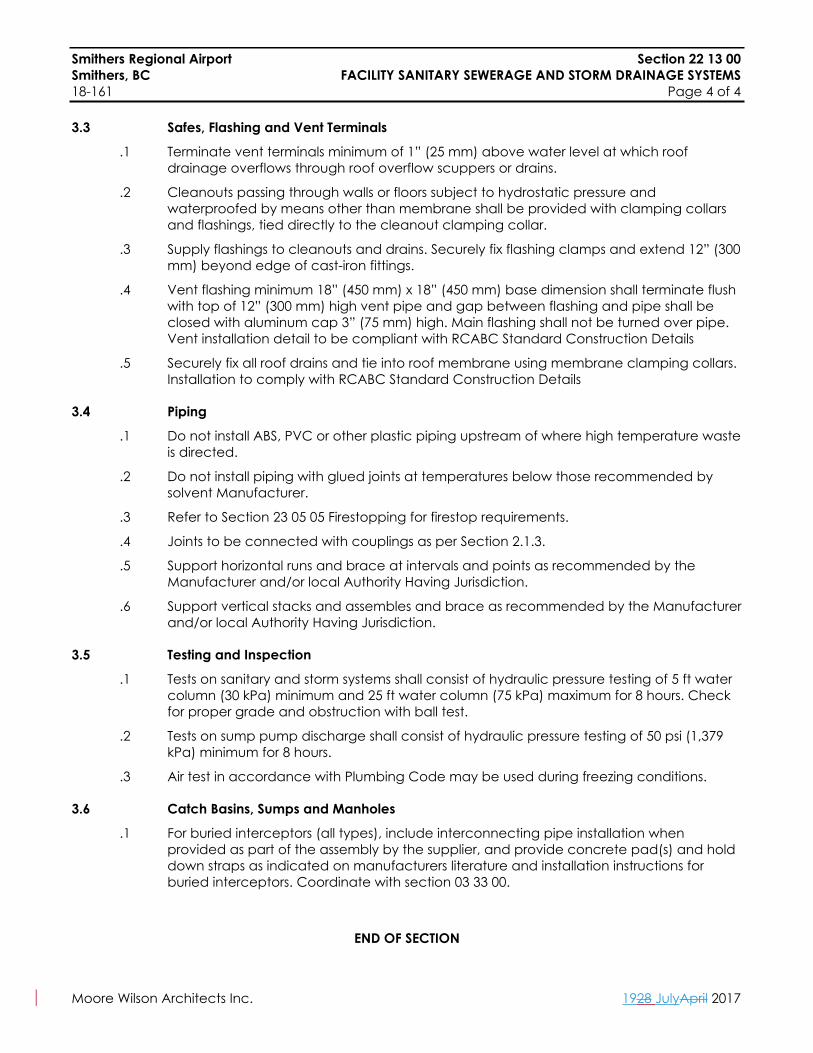
3.3 Safes, Flashing and Vent Terminals
.1 Terminate vent terminals minimum of 1” (25 mm) above water level at which roof drainage overflows through roof overflow scuppers or drains.
.2 Cleanouts passing through walls or floors subject to hydrostatic pressure and waterproofed by means other than membrane shall be provided with clamping collars and flashings, tied directly to the cleanout clamping collar.
.3 Supply flashings to cleanouts and drains. Securely fix flashing clamps and extend 12” (300 mm) beyond edge of cast-iron fittings.
.4 Vent flashing minimum 18” (450 mm) x 18” (450 mm) base dimension shall terminate flush with top of 12” (300 mm) high vent pipe and gap between flashing and pipe shall be closed with aluminum cap 3” (75 mm) high. Main flashing shall not be turned over pipe. Vent installation detail to be compliant with RCABC Standard Construction Details
.5 Securely fix all roof drains and tie into roof membrane using membrane clamping collars. Installation to comply with RCABC Standard Construction Details
3.4 Piping
.1 Do not install ABS, PVC or other plastic piping upstream of where high temperature waste is directed.
.2 Do not install piping with glued joints at temperatures below those recommended by solvent Manufacturer.
.3 Refer to Section 23 05 05 Firestopping for firestop requirements.
.4 Joints to be connected with couplings as per Section 2.1.3.
.5 Support horizontal runs and brace at intervals and points as recommended by the Manufacturer and/or local Authority Having Jurisdiction.
.6 Support vertical stacks and assembles and brace as recommended by the Manufacturer and/or local Authority Having Jurisdiction.
3.5 Testing and Inspection
.1 Tests on sanitary and storm systems shall consist of hydraulic pressure testing of 5 ft water column (30 kPa) minimum and 25 ft water column (75 kPa) maximum for 8 hours. Check for proper grade and obstruction with ball test.
.2 Tests on sump pump discharge shall consist of hydraulic pressure testing of 50 psi (1,379 kPa) minimum for 8 hours.
.3 Air test in accordance with Plumbing Code may be used during freezing conditions.
3.6 Catch Basins, Sumps and Manholes
.1 For buried interceptors (all types), include interconnecting pipe installation when provided as part of the assembly by the supplier, and provide concrete pad(s) and hold down straps as indicated on manufacturers literature and installation instructions for buried interceptors. Coordinate with section 03 33 00.
END OF SECTION
Smithers Regional Airport Section 23 81 10Smithers, BC PACKAGED HEATING AND COOLING EQUIPMENT18-161 Page 1 of 3
Moore Wilson Architects Inc. 1928 JulyApril 2017
Part 1 General
1.1 Related Work
.1 This Specification Section forms part of Contract Documents and are to be read, interpreted and coordinated with other parts.
1.2 Warranty
.1 Refrigeration compressors to be warrantied for five years.
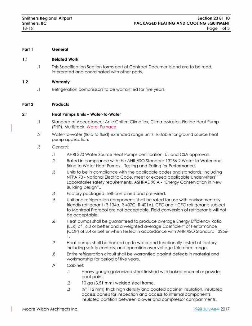
Part 2 Products
2.1 Heat Pumps Units – Water-to-Water
.1 Standard of Acceptance: Artic Chiller, Climaflex, ClimateMaster, Florida Heat Pump (FHP), Multistack, Water Furnace
.2 Water-to-water (fluid to fluid) extended range units, suitable for ground source heat pump application.
.3 General:
.1 AHRI 320 Water Source Heat Pumps certification, UL and CSA approvals.
.2 Rated in compliance with the AHRI/ISO Standard 13256-2 Water to Water and Brine to Water Heat Pumps – Testing and Rating for Performance.
.3 Units to be in compliance with the applicable codes and standards, including NFPA 70 - National Electric Code, meet or exceed applicable Underwriters’’ Laboratories safety requirements, ASHRAE 90 A - “Energy Conservation in New Building Design”..
.4 Factory packaged, self-contained and pre-wired.
.5 Unit and refrigeration components shall be rated for use with environmentally friendly refrigerant (R-134a, R-407C, R-401A). CFC and HCFC refrigerants subject to Montreal Protocol are not acceptable. Field conversion of refrigerants will not be acceptable.
.6 Heat pumps shall be guaranteed to produce average Energy Efficiency Ratio (EER) of 16.0 or better and a weighted average Coefficient of Performance (COP) of 3.4 or better when tested in accordance with AHRI/ISO Standard 13256-1.
.7 Heat pumps shall be hooked up to water and functionally tested at factory, including safety controls, and operation over voltage tolerance range.
.8 Entire refrigeration circuit shall be warrantied against defects in material and workmanship for period of five years.
.9 Cabinet:.1 Heavy gauge galvanized steel finished with baked enamel or powder
coat paint..2 10 ga (3.51 mm) welded steel frame..3 ½” (12 mm) thick high density and coated cabinet insulation, insulated
access panels for inspection and access to internal components, insulated partition between blower and compressor compartments.

Smithers Regional Airport Section 23 81 10Smithers, BC PACKAGED HEATING AND COOLING EQUIPMENT18-161 Page 2 of 3
Moore Wilson Architects Inc. 1928 JulyApril 2017
.4 Galvanized steel condensate drain pan. Pan insulated and pitched for drainage.
.5 If the mechanical contractor submits an alternate WSHP, the contractor is responsible for ensuring that all additional sensors/controls required to meet the sequence of operations (such as external flow sensors if not included in the alternate product) are installed.
.10 Compressor:.1 Heat pump duty hermetic, internally sprung and externally isolated..2 Thermal overload protection..3 Thermal expansion device to meter refrigerant between air and water
coils. Capillary tubes not acceptable..4 Compressor motor overload protection..5 Capability to reset compressor lockout circuit at either remote thermostat
or circuit breaker..6 Insulated compressor (high density sound attenuating blanket) for noise
attenuation..11 Refrigerant Loop and Reversing Valve:
.1 Factory-sealed refrigeration system, insulated with minimum 3⁄8” (10 mm) elastomeric insulation.
.2 Schrader access valves on high and low pressure lines.
.3 Insulated refrigerant loop to prevent condensation at low temperatures.
.4 Liquid line filter dryers in each refrigerant circuit.
.5 High and low temperature cut-outs.
.6 Hermetic construction with replaceable external electrical solenoid coil.
.7 Reversing valve shall be pilot operated sliding piston type with replaceable encapsulated magnetic coil.
.12 Water Coil:.1 Axial tube-in-tube type with water flowing through inner serpentine
copper coil, with cupronickel inner tube designed for low water pressure drop and low water flow, or brazed plate type heat exchangers with 316 stainless steel plates capable of withstanding 650 psi (4,480 kPa) working pressure on refrigerant side and 450 psi (3,105 kPa) on water side.
.2 Insulated to prevent condensation. Insulation shall be manufactured without use of CFCs or HCFs.
.13 Control Panel:.1 Controls shall interface with BMS via acceptable approved gateway –
BACnet or equal. BMS shall monitor room temperature and provide start stop signal, and supply air temperature re-set signal.
.2 Factory wired and mounted control circuit complete with compressor contactor, 24 V transformer and blower relay.
.3 Controls shall include high pressure and freeze protectors.
.4 Relays and transformers suitable for 24 V remote control.
.5 Lock-out relay reset from BMS.
.6 Status and alarm monitoring through BMS.

Smithers Regional Airport Section 23 81 10Smithers, BC PACKAGED HEATING AND COOLING EQUIPMENT18-161 Page 3 of 3
Moore Wilson Architects Inc. 1928 JulyApril 2017
.4 Accessories:
.1 Hanger/vibration isolator kit complete with brackets.
.2 Controller capable supporting building DDC system protocol.
.3 Hose kits - hose kits shall include two 12” (300 mm) long flexible reinforced rubber hoses (rated at 200 psi (1,380 kPa) working pressure) with brass pipe connections (swivel on one end).
.4 One spare set of filters for each unit.
Part 3 Execution
3.1 General
.1 Install units as indicated and to Manufacturer’s recommendations.
.2 For all water or glycol cooled units, the connecting hose kit shall be complete with autoflow controlled flow valve, supply and return isolation valves, wye strainer on supply side pipe (minimum of 60 mesh), P+T ports and local drain on terminal side of isolation valves for unit maintenance.
3.2 Equipment Preparation and Start-Up
.1 Provide services of Manufacturer’s Field Engineer to set and adjust equipment for operation as specified.
3.3 Heat Pump Unit Installation
.1 Install in accordance with Manufacturer’s recommendations.
.2 Piping connections to units shall be flexible hoses.
.3 P/T plugs shall be provided on supply and return piping connections to each unit.
.4 Install temporary bypass piping arrangement, using flexible hoses, before piping is chemically cleaned. Replace permanent connections after piping has been flushed out.
.5 Manufacturer’s Representative to check out and start-up units.
END OF SECTION

Smithers Regional Airport Section 25 05 01Smithers, BC DIRECT DIGITAL CONTROLS18-161 Page 1 of 21
Moore Wilson Architects Inc. 1928 JulyApril 2017
Part 1 General
1.1 Conformance
.1 All Sections of Mechanical Specifications form part of Contract Documents and are to be read, interpreted and coordinate with all parts. Conform to General Conditions and Division 00, 01, instructions to Bidders, Contract General Conditions and Supplements thereto form part of this Division and contain items related to mechanical work.
1.2 Work Included
.1 Complete system of automatic controls.
.2 Electronic facilities management/DDC control system.
.3 Control devices, components, wiring and material.
.4 Instructions to Owner.
.5 Provide all system source Codes (programming) to Owner.
.6 Bidders shall provide compliance/non-compliance and partial compliance statement for each item in this specification and sign off on each item of the specified items. Where non-compliant, the bidder shall provide an explanation and date on alternative provisions.
1.3 Quality Assurance
.1 Provide a complete system of automatic controls for mechanical systems by firms employing certified journeymen who specialize in this type of work and have proof of completing five projects of similar size and complexity.
.2 It is the Contractor’s responsibility to provide all items required to complete the installation, including but not limited to, all computer software and hardware, operator input/output devices, remote panels, sensors, controls, required to meet the performance requirements as set forth in this Section. The Contractor shall provide all wring piping, raceways, conduit, installation supervision and labour, including calibration, adjustments and checkouts necessary for a complete and operational system. Acceptable Controls Vendors are as follows:
.1 ESC Delta
.2 Houle Controls
.3 Reliable Controls
.4 Johnson Controls
1.4 Submittals
.1 Submit shop drawings in accordance with Section 23 05 00.
.2 Provide damper shop drawings which include data such as location, arrangement, velocities and static pressure drops for each system. Provide data for all control valve sizing including pressure drops with control valve shop drawing submission.

Smithers Regional Airport Section 25 05 01Smithers, BC DIRECT DIGITAL CONTROLS18-161 Page 2 of 21
Moore Wilson Architects Inc. 1928 JulyApril 2017
.3 Include complete operating data, component setpoints, system drawings, wiring diagrams, installed program flow charts and program listing, written detailed sequences of operation and engineering data on each control system component. Include sizing as requested. Components are to be labelled and identified as to use. Submit to Mechanical Contractor for inclusion in Operating and Maintenance Manuals.
.4 Provide, in addition to shop drawing submittals, a detailed list of maintenance instructions including daily, weekly, monthly and annual maintenance requirements for each component of the automatic control system. Copy to be included in the Mechanical Maintenance Manuals in the Maintenance and Lubrication Tab.
.5 Label components on drawings and identify as to function.
.6 Submit CDs, including backup CDs, with up-to-date programs in each controller. Provide original program CDs for each software package complete with validated registrations.
1.5 Substantial Completion Test Procedures
.1 Before the seven day acceptance test may begin, the DDC system must be completely operational including the following:
.1 Every point shall be checked end-to-end to ensure accuracy and integrity of the system. Each point shall appear on a points list (to be prepared by the Contractor) and be signed off by both persons involved in the commissioning procedure.
.2 Basic control strategies shall be written in user-friendly control language. Major system problems preventing accurate control shall be reported in writing by the Contractor.
.3 Provide program flow charts for installed program.
.4 The measured variable, controlled variable and setpoint if calculated of each control loop should be placed on a 15 minute continuous trend for at least 24 hours to prove stability of loop.
.5 Each space sensor should be placed on a three hour trend for 100 samples.
.6 Run time totalizer should be set on all digital outputs.
.7 Load/save of panel programs must be demonstrated.
.8 All features of system shall be exercised
.9 Operator shall be briefed on operation of system, using a minimum of one 8 hour work day.
.10 A trend in one panel will be set up for a point from another panel. This point should also be trended in its own panel for the same intervals. Comparison of the two trends will indicate if any communication problems are occurring during the seven day test.
.11 Related binary inputs/outputs and related status points shall be connected to show alarm condition.
1.6 Documentation
.1 The following documentation must be in place before completion of the test and substantial acceptance is granted:
.1 Panel layout sheets complete with point name, point address and wire identification number. One copy attached to each respective panel door.
.2 All points tagged with point name, point address and panel number.
.3 As-built control drawings.
Smithers Regional Airport Section 25 05 01Smithers, BC DIRECT DIGITAL CONTROLS18-161 Page 3 of 21
Moore Wilson Architects Inc. 1928 JulyApril 2017
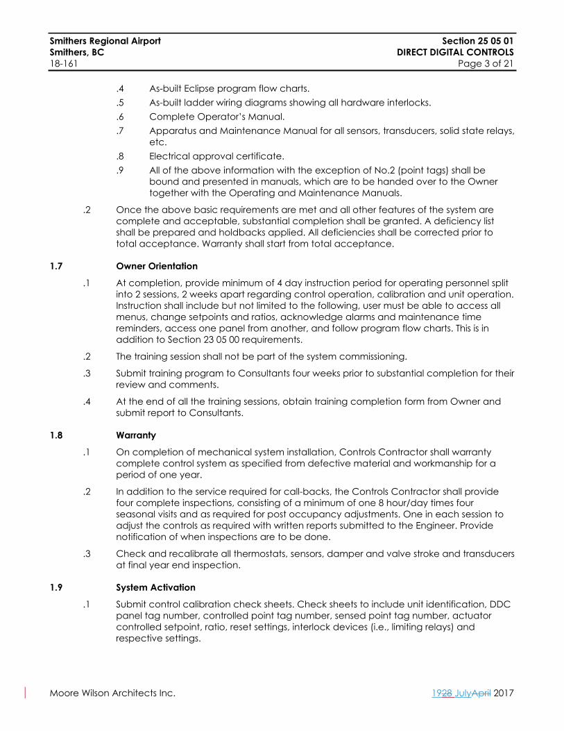
.4 As-built Eclipse program flow charts.
.5 As-built ladder wiring diagrams showing all hardware interlocks.
.6 Complete Operator’s Manual.
.7 Apparatus and Maintenance Manual for all sensors, transducers, solid state relays, etc.
.8 Electrical approval certificate.
.9 All of the above information with the exception of No.2 (point tags) shall be bound and presented in manuals, which are to be handed over to the Owner together with the Operating and Maintenance Manuals.
.2 Once the above basic requirements are met and all other features of the system are complete and acceptable, substantial completion shall be granted. A deficiency list shall be prepared and holdbacks applied. All deficiencies shall be corrected prior to total acceptance. Warranty shall start from total acceptance.
1.7 Owner Orientation
.1 At completion, provide minimum of 4 day instruction period for operating personnel split into 2 sessions, 2 weeks apart regarding control operation, calibration and unit operation. Instruction shall include but not limited to the following, user must be able to access all menus, change setpoints and ratios, acknowledge alarms and maintenance time reminders, access one panel from another, and follow program flow charts. This is in addition to Section 23 05 00 requirements.
.2 The training session shall not be part of the system commissioning.
.3 Submit training program to Consultants four weeks prior to substantial completion for their review and comments.
.4 At the end of all the training sessions, obtain training completion form from Owner and submit report to Consultants.
1.8 Warranty
.1 On completion of mechanical system installation, Controls Contractor shall warranty complete control system as specified from defective material and workmanship for a period of one year.
.2 In addition to the service required for call-backs, the Controls Contractor shall provide four complete inspections, consisting of a minimum of one 8 hour/day times four seasonal visits and as required for post occupancy adjustments. One in each session to adjust the controls as required with written reports submitted to the Engineer. Provide notification of when inspections are to be done.
.3 Check and recalibrate all thermostats, sensors, damper and valve stroke and transducers at final year end inspection.
1.9 System Activation
.1 Submit control calibration check sheets. Check sheets to include unit identification, DDC panel tag number, controlled point tag number, sensed point tag number, actuator controlled setpoint, ratio, reset settings, interlock devices (i.e., limiting relays) and respective settings.

Smithers Regional Airport Section 25 05 01Smithers, BC DIRECT DIGITAL CONTROLS18-161 Page 4 of 21
Moore Wilson Architects Inc. 1928 JulyApril 2017
.2 Provide attendance as required by Balancing and Commissioning Agents to set damper linkages; adjust to and set variable volume control and tracking devices and static pressure controls. Verify outdoor air flow rate at eight damper positions to ensure damper position corresponds to flow rate. Control calibrate algorithm to match air flow and damper position.
.3 Adjust and calibrate all room sensors. Confirm proper operation of all terminal box and radiation valve control and sequencing.
Part 2 Products
2.1 General
.1 Provide control systems consisting of operator’s devices, indicating devices, interface equipment and other apparatus required to operate mechanical system and to perform functions specified. Identify all components in field by plastic nameplate, and/or non-rip point baggage tags.
.2 Provide materials and field work necessary to connect control components factory supplied as part of packaged equipment.
.3 Unless specified otherwise, provide fully proportional components.
.4 Provide labelled terminal strip connection in each unit and panel connection to external controls.
2.2 Electrical Components, Wiring and Conduit
.1 Wiring and Conduit:
.1 By Electrical Trade:.1 All power supply wiring to mechanical equipment..2 All power supply wiring and conduit to main control panels..3 All smoke detectors and wiring associated with life safety shut-down and
start-up of air handling systems..2 By Mechanical Trade:
.1 All control system low voltage wiring.
.2 Conduits for control wiring and components associated with the mechanical work. All low and line voltage control wiring shall be in EMT conduit in accordance with Electrical specifications.
.3 All low and line voltage control wiring and conduit for specified motor interlocks.
.4 Power wiring from electrical panel to control transformers distributed round the building.
.2 Components
.1 By Electrical Trade:.1 All disconnect switches except as specified in Mechanical Equipment
Schedules..2 All motor protection switches, magnetic starters and contactors..3 All line voltage relays to power and control mechanical equipment..4 All wiring to and from variable speed drives supplied by mechanical
trade.

Smithers Regional Airport Section 25 05 01Smithers, BC DIRECT DIGITAL CONTROLS18-161 Page 5 of 21
Moore Wilson Architects Inc. 1928 JulyApril 2017
.2 By Mechanical Trade:.1 All temperature control systems components and packaged equipment
controls, relays and transformers..2 All disconnect switches, relays, transformers as specified in Mechanical
Equipment Schedules..3 All thermostats, dampers, damper motors, timer clocks and control panels..4 All low voltage transformers to power mechanical equipment controls..5 All power wiring (120 V/1 Ph) to controls transformers, control panels and
control devices requiring 120 V/1 Ph power wiring (infrared flush meters etc.)
.3 Minimum Wiring Requirements:
.1 All exposed wiring and wiring located above removable, acoustic ceiling tiles shall be run in plenum rated, 18 gauge, two wire, twisted, shielded pair. Two wire twisted pair shall be acceptable for sensor wiring or output; coaxial cable shall be acceptable for transmission wiring. Plenum rated wiring not in EMT conduit shall be run neatly bunched in J-hooks in a rectilinear fashion, running parallel to building. Cable lines must be run at least 12” (300 mm) above ceiling. Where controls cables and wiring is run through, or in “exposed ceilings”, all wiring and cables shall be run in conduit. Where permission has been gained to run in a cable tray, only then can conduit be deleted, except for branches from the cable and individual run-outs.
.2 Alternating current wiring over 24 V, both line and low voltage, shall not be run in the same conduit or cable with direct current signals. Direct current signals include communications wiring, analog input wiring, digital input wiring and analog output wiring. 24 V AC and 0-10 V DC may be run together.
.3 Low voltage direct curring wiring shall be 2-wire shielded, twisted pair, minimum 18 gauge.
.4 Line voltage alternating current wiring shall be copper conductor, minimum 16 gauge.
.5 Low voltage alternating current wiring shall be copper conductor, minimum 18 gauge.
.6 Under no circumstances shall the Mechanical Controls Trade run controls cabling or wiring in the Electrical cable tray system without prior written permission from the Electrical Consultant and the Electrical Contractor. Unless otherwise agreed or directed, all control cabling and wiring shall be run independently in conduits and/or separate raceways to be provided by the Controls Trade for their own use.
2.3 Controllers
.1 The standalone digital control panels shall be microprocessor based, multi-tasking, multi-user, real-time digital control processors capable of operating independently of other controllers in the network. All unitary controllers, air handling unit controllers and VAV controllers shall operate as stand alone controllers.
.2 Each standalone panel shall consist of modular hardware with plug-in enclosed processors, communication controllers, power supply and input/output modules. All plug-in printed circuit boards shall allow flexibility in application and rapid repair. All wiring within the standalone panels shall be labelled and run in raceway to accommodate servicing. The control panel shall contain a battery backed real time clock synchronized with other real time clocks in the network.
Smithers Regional Airport Section 25 05 01Smithers, BC DIRECT DIGITAL CONTROLS18-161 Page 6 of 21
Moore Wilson Architects Inc. 1928 JulyApril 2017
.3 Surge and Transient Protection: Isolation shall be provided at all network terminations, as well as all field point terminations, to suppress induced voltage transients consistent with IEEE Standard 587-1980.
.4 Analog to digital and digital to analog conversions shall have a minimum of 12 bit resolution.
.5 All input points shall be universal in nature, allowing their individual function definition to be assigned through the application software. All unused input points must be available as universally definable at the discretion of the Owner. If the input points are not fully universal in nature, unused points must be equal in quantity between analog inputs and digital inputs.
.6 Allow 10% minimum 10% spare capacity in each DDC ‘Building Controller’, and ‘Application Specific Controllers’ control panels for all point types.
.7 All control sequences programmed into the standalone digital controller shall be stored in non-volatile memory, which is not dependent upon the presence of a battery, to be retained. Power failures shall not cause the stand alone digital controller memory to be lost, nor shall there be any need for batteries to be recharged or replaced to maintain the integrity of the controller database.
.8 Any mechanical equipment which is required to operate on emergency power shall be controlled by a controller that is supplied by emergency power circuit connected to backed up generator and UPS power. The UPS power shall be provided by the Controls Contractor unless specifically noted otherwise in Electrical documentation. The DDC system shall monitor the generator and transfer switch so that appropriate action can be taken to the DDC system in the event of emergency power operation. Allow for all Electrical equipment.
.9 All sensing inputs shall be provided via the following industry standards:
.1 0 to 10 VDC
.2 4 to 20 mA.
.3 Resistance signals (1000 ohms, 10k Thermistor – nickel or platinum RTD’s).
.4 Binary inputs shall be provided with filtering to eliminate false signals resulting from input bouncing.
.5 Counter inputs shall monitor dry contact pulses with an input resolution of 1 Hz minimum.
.10 Digital outputs shall provide SPDT output contracts and be capable of directly switching the following voltages:
.1 24 VAC at 36 VA operating/360 VA inrush.
.2 102 VAC at 180 VA operating/1800 VA inrush.
.3 240 VAC at 180 VA operation/1800 VA inrush.
.11 Digital outputs shall be optically isolated from the controller’s electronic circuit.
.12 Control panel diagnostics shall consist of built-in, continuous operational and board level tests, software control sequence analysis and alarm exception logging. Light emitting diodes and/or the alphanumeric display shall annunciate hardware failures and control program errors or problems.
.13 Provide one individual standalone control panel for every mechanical system. Where mechanical equipment items provide system redundancy, failure of the panel shall not result in failure of control of multiple mechanical equipment items.
Smithers Regional Airport Section 25 05 01Smithers, BC DIRECT DIGITAL CONTROLS18-161 Page 7 of 21
Moore Wilson Architects Inc. 1928 JulyApril 2017
.14 The standalone control panels shall interface to additional panels of equipment as required to meet the performance specification. Each standalone panel shall be provided with an interface port for the hand held operator’s terminal.
.15 Any remote panel malfunction shall not affect the proper operation of the system or other remote panels.
.16 All stand-alone control panels shall give full access to programming while communicating from a remote location (over the Internet/Intranet).
2.4 Field Control Devices
.1 Temperature Sensors:
.1 Shall be resistance type and shall be either 2-wire 1000 ohm nickel RTD or 2-wire 1000 ohm platinum RTD or 10K thermister type. Sensor shall have service tool communicating jack for interface with laptop computer service tool for adjustment and troubleshooting.
.2 Shall be available for room, duct, outside or well mounting with proper ranges to suit application.
.3 Shall give an end-to-end accuracy of not less that ±32.45°F (±0.25°C).
.4 All room sensors shall be surface mount and complete with integral LCD display (room temperature, setpoint temperature, occupancy mode and fan status where override is specified), ±37.4°F (±3°C) setpoint adjustment and occupancy mode override push button and service tool communication jack for interface with laptop computer or service tool for adjustment and troubleshooting.
.5 Outdoor air sensor shall be provided with solar shields and perforated plate to minimize solar and wind effects and transmitter shall be NEMA 3R construction.
.6 Duct sensors shall be in insertion type complete with locking nut and mounting plate. Mounting box shall be weatherproof for all outdoor applications. Where duct dimension is greater than 48” (1,200 mm) averaging sensors complete with capillary support shall be used.
.7 Immersion wells shall be of stainless steel materials for domestic water systems and brass for other applications. Heat transfer compound shall be compatible with sensor. Sensor to be spring loaded construction with compression fitting for (20 mm) stainless steel sheathed construction.
.8 HVAC Dual-Temp analogue temperature gauge and electrical temperature well: in lieu of providing separate analogue pipe temperature gauges thermowells and DDC pipe temperature thermowells, the controls contractor shall supply Wika brand dual-temp thermometer/transmitter, Model TR40/TW15 complete with TI.52 dial gauge. Supplier contact: JB5A, 604-590-8866, www.wika.ca
.2 Motor Current Sensors:
.1 Shall have linear output proportional to the motor current draw.
.2 Sensor shall connect to the controller by means of a 2-wire cable.
.3 Sensor shall have dual HI/LO range selector.
.4 Sensor shall have an accuracy of 1% of full scale, maximum response time of 100 milliseconds and a loading error not greater than .25% with a 1 megaohm load.
.3 Differential Pressure Sensors:
.1 Shall vary the output voltage with changes in differential pressure.
.2 Shall connect to the controller by means of a 2-wire cable.
Smithers Regional Airport Section 25 05 01Smithers, BC DIRECT DIGITAL CONTROLS18-161 Page 8 of 21
Moore Wilson Architects Inc. 1928 JulyApril 2017
.3 Shall have an end-to-end accuracy of not less than ±1% of span including non-linearity and hysteresis.
.4 Static Pressure Sensors Shall:
.1 Vary the output voltage with changes in static pressure.
.2 Connect to the controller by means of a 2-wire cable.
.3 Have an end-to-end accuracy of not less than ±1% of span including non-linearity and hysteresis.
.5 Humidity Sensors Shall:
.1 Be equipped with non-interactive span and zero adjustment complete with 2-wire isolated loop powered 4-20 mA 0-100% linear proportional output. Sensing probe shall be constructed of Type 304 stainless steel.
.2 Have a control range of 20% to 80%.
.3 Have an accuracy of plus or minus 3% RH over an ambient temperature range of 70°F (21°C) to 80.6°F (27°C).
.6 Airflow Measuring Stations Shall:
.1 Vary the output voltage with changes in supply and return airflow. The airflow traverse probe, which shall be capable of producing steady non-pulsating signals, consists of multiple total and static pressure sensors placed at equal distances as per ASHRAE Standards for duct traversing.
.2 Connect to the controller by means of a 2-wire cable.
.3 Have end-to-end accuracy for variable volume control of not less than ±0.05% of the airflow.
.4 Acceptable Manufacturers: Air Monitor Corp., Tek-Air Systems Inc., Ebtron Gold Series - G7x116 P+, or Ebtron Elf for ≤ 14” (350 mm) Ø ducts.
.7 Room Occupancy Sensors – Wattstopper C1-12, C1-24 Passive Infrared HVAC/BAS Ceiling Sensor or Equal
.1 12 VDC or 24 VAC/VDC supply power, UL/ULC listed.
.2 Complete with five (5) year warranty, dual element, temperature compensated pyro-electric sensor.
.3 Complete with time delay adjustment 30 seconds to 30 minutes.
2.5 Line Filters
.1 The line filter shall be rated at 3A, 250 VAC, 50/60 Hz and shall be capable of filtering out electromagnetic interference.
2.6 Control Valves
.1 Provide valves in accordance with general valve specification with maximum 3 psi (21 kPa) pressure drop.
.2 Valves shall “fail-safe”, spring return to normal position. 2-way and 3-way valves for liquids shall have either equal percentage or linear characteristics. Size 2-way valve operators to close against maximum pump shutoff head. Control valve coefficient shall be determined with the valve in the 100% open position. Control valves using a limited stroke to create the required flow coefficient shall not be acceptable.
.3 All control valves shall be threaded type. All valve bodies shall have a replaceable packing gland.

Smithers Regional Airport Section 25 05 01Smithers, BC DIRECT DIGITAL CONTROLS18-161 Page 9 of 21
Moore Wilson Architects Inc. 1928 JulyApril 2017
.4 Control valves shall be globe type with modulating electronic actuator. Actuators for valves on larger coils in air handlers shall have spring return to normal position. 2-way and 3-way valves for liquids shall have equal percentage characteristic. Maximum shut off head leakage shall not exceed 1% of full design flow.
.1 Acceptable Product: Griswold Automizer, Belimo CCV Characterized Control Valve.
2.7 Pressure Independent Control Valves (PIV’s)
.1 Provide valves in accordance with general valve specification with maximum 3 psi (20 kPa) pressure drop.
.2 Valves shall ‘fail-safe’, spring return to normal position. 2-way and 3-way valves for liquids shall have either equal percentage or linear characteristics. Size 2-way valve operators to close against maximum pump shutoff head. Control valve coefficient shall be determined with the valve in the 100% open position. Control valves using a limited stroke to create the required flow coefficient shall not be acceptable.
.3 All control valves shall be threaded type. All valve bodies shall have a replaceable packing gland.
.4 Control valves shall be pressure independent against a differential pressure of 5-50PSI with modulating electronic actuator.
.5 Acceptable product: Belimo PICV, Griswold PICV and Tour and Anderson PICV
2.8 Dampers
.1 Automatic dampers shall be 14 ga (1.63 mm) extruded aluminum multiple blade mounted to 4” (100 mm) extruded aluminum flanged frame. Frame shall be installed with polystyrene on all four sides. Frame seals shall be of extruded TPE. Individual blades shall be internally insulated thermally broken extruded aluminum not exceeding 8” (200 mm) in width or in length with interlocking edges and compressible seals. Blade gaskets shall be of extruded EPDM. Provide oil impregnated bronze or nylon bearings with additional thrust bearings for vertical blades. Dampers exposed to outside air or used as exterior isolation dampers shall be AMCA rated for leakage less than 4 cfm per ft2 (21 l/s per m2) against 4” w.g. (1,000 Pa) static pressure differential. Dampers exposed to outside air or used as exterior isolation dampers shall be equal to TAMCO Series 9000. Dampers for return or recirculating air shall be AMCA rated for leakage less than 10.3 cfm per ft2 (52 l/s per m2) against 4” w.g. (1,000 Pa) static pressure differential. Dampers shall be equal to TAMCO Series 1000.
.2 Mixing dampers of parallel blade construction arranged to mix streams.
.3 Dampers have less than ½% leakage and be equal to Ruskin CD-36.
2.9 Damper Operators
.1 Piston or gear driving type damper operators with spring return to “fail-safe” in normally open or normally closed position. Non-mechanical forms of fail-safe operation are not acceptable.
.2 Damper actuators shall be electronic direct-coupled over the shaft. Actuators shall have electronic overload or digital rotation sensing circuitry to prevent damage to the actuator. Mechanical end switches and magnetic clutches are not acceptable.
Smithers Regional Airport Section 25 05 01Smithers, BC DIRECT DIGITAL CONTROLS18-161 Page 10 of 21
Moore Wilson Architects Inc. 1928 JulyApril 2017
.3 Proportional actuators shall accept a 0-10 VDC or 0-20 mA control input signals and shall provide a 2-10 VDC or 4-20 mA position feedback signals. Pulse width modulating control is acceptable.
.4 All modulating actuators shall have an external built-in switch to allow the reversing of direction of rotation.
2.10 Variable Air Volume Terminal Unit Digital Controllers
.1 Digital controllers shall be configurable, standalone, networked direct digital controllers consisting of a microprocessor, power supply, actuator, integral dead-ended differential pressure transducer and operation/application system software in a single integrated package complete with manual positioning. The digital controllers shall utilize proportional plus integration algorithm for the space temperature control drops.
.2 Digital controllers shall comply with ASHRAE Standard 90.1 and shall include compliant interface for ASHRAE Standards 62.1 -2007.
2.11 Special Gas Monitoring System
.1 CO/Propane/Gasoline Sensors:
.1 General: Dual channel, self-contained gas detection system for the monitoring of carbon monoxide and propane/gasoline vapours, housed in a wall mount, drip-proof PVC enclosure with hinged, secured door. System power shall be 24 VDC or 24 VAC (nominal). A CSA certified, totally enclosed step down transformer shall be supplied as required to reduce voltage from 120 V.
.2 Sensors: The system shall have one integral electrochemical CO sensor and one remote analog transmitter with a solid-state combustible gas sensor. The measurement range shall be 0 – 200 ppm CO in air and 0-50% LEL C3H8 (Propane) in air. Area of monitoring coverage is up to 5,000 ft2 (464.51 m2) to 7,000 ft2 (650 m2) per sensor.
.3 Monitors: The monitor shall provide a tri-colour indicating light for power, low alarm, high alarm and fault condition, audible alarm with silence push-button and two SPDT dry contact alarm relays rated 5 amps at 240 VAC each. There shall be a LED digital display of concentration. The system must meet WCB workplace hazardous gas exposure standards. System controller shall be capable of supporting up to 128 digital transmitters on a RS-485 communication bus. System shall support analog output modules (eight 4-20 mA outputs per module) and relay output modules (eight 5 A SPDT relays per digital network (two low voltage power wires and a twisted pair for the communication bus). System power requirement is 100 to 240 VAC, 47 to 63 Hz. The controller shall provide a circuit test button to allow the user to confirm system operation and exhaust fan control from the panel. The controller shall also provide a push-button to allow the user to override the system control and operate exhaust fans continuously for 15-minute segments to evacuate air from specific parts of the building. The controller shall automatically test the electrochemical CO sensor failure. The controller shall provide automatic “calibration due” notification to the end user. Connect to DDC system to provide alarms.
Smithers Regional Airport Section 25 05 01Smithers, BC DIRECT DIGITAL CONTROLS18-161 Page 11 of 21
Moore Wilson Architects Inc. 1928 JulyApril 2017
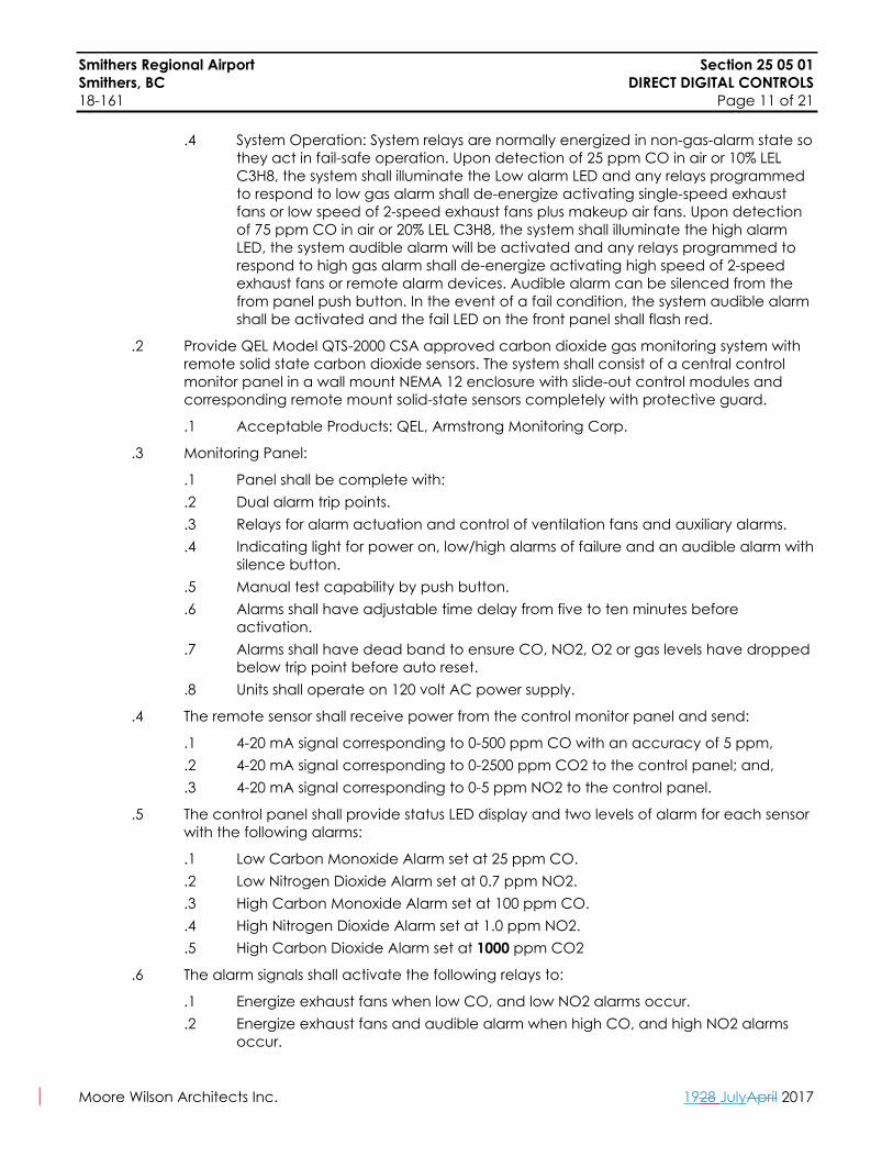
.4 System Operation: System relays are normally energized in non-gas-alarm state so they act in fail-safe operation. Upon detection of 25 ppm CO in air or 10% LEL C3H8, the system shall illuminate the Low alarm LED and any relays programmed to respond to low gas alarm shall de-energize activating single-speed exhaust fans or low speed of 2-speed exhaust fans plus makeup air fans. Upon detection of 75 ppm CO in air or 20% LEL C3H8, the system shall illuminate the high alarm LED, the system audible alarm will be activated and any relays programmed to respond to high gas alarm shall de-energize activating high speed of 2-speed exhaust fans or remote alarm devices. Audible alarm can be silenced from the from panel push button. In the event of a fail condition, the system audible alarm shall be activated and the fail LED on the front panel shall flash red.
.2 Provide QEL Model QTS-2000 CSA approved carbon dioxide gas monitoring system with remote solid state carbon dioxide sensors. The system shall consist of a central control monitor panel in a wall mount NEMA 12 enclosure with slide-out control modules and corresponding remote mount solid-state sensors completely with protective guard.
.1 Acceptable Products: QEL, Armstrong Monitoring Corp.
.3 Monitoring Panel:
.1 Panel shall be complete with:
.2 Dual alarm trip points.
.3 Relays for alarm actuation and control of ventilation fans and auxiliary alarms.
.4 Indicating light for power on, low/high alarms of failure and an audible alarm with silence button.
.5 Manual test capability by push button.
.6 Alarms shall have adjustable time delay from five to ten minutes before activation.
.7 Alarms shall have dead band to ensure CO, NO2, O2 or gas levels have dropped below trip point before auto reset.
.8 Units shall operate on 120 volt AC power supply.
.4 The remote sensor shall receive power from the control monitor panel and send:
.1 4-20 mA signal corresponding to 0-500 ppm CO with an accuracy of 5 ppm,
.2 4-20 mA signal corresponding to 0-2500 ppm CO2 to the control panel; and,
.3 4-20 mA signal corresponding to 0-5 ppm NO2 to the control panel.
.5 The control panel shall provide status LED display and two levels of alarm for each sensor with the following alarms:
.1 Low Carbon Monoxide Alarm set at 25 ppm CO.
.2 Low Nitrogen Dioxide Alarm set at 0.7 ppm NO2.
.3 High Carbon Monoxide Alarm set at 100 ppm CO.
.4 High Nitrogen Dioxide Alarm set at 1.0 ppm NO2.
.5 High Carbon Dioxide Alarm set at 1000 ppm CO2
.6 The alarm signals shall activate the following relays to:
.1 Energize exhaust fans when low CO, and low NO2 alarms occur.
.2 Energize exhaust fans and audible alarm when high CO, and high NO2 alarms occur.

Smithers Regional Airport Section 25 05 01Smithers, BC DIRECT DIGITAL CONTROLS18-161 Page 12 of 21
Moore Wilson Architects Inc. 1928 JulyApril 2017
.7 The system shall energize the exhaust fans on sensing loss of signal from sensor and/or under range signal from the fail relay.
.8 Sensors shall be warrantied for two years and sensor life shall be three years.
.9 Install system in complete accord with Manufacturer’s recommendations.
2.12 Energy Meters
.1 BTU meters shall be tamper-proof and equal to ISTA Energy meter complete with building DDC system interface for monitoring heating and or cooling consumption. The system shall consist of temperature sensors, flowmeters and electronic calculating unit. System shall be rated for 3 VDC with power convertors connected to 24 VAC. Battery shall be rated for a minimum operating life of six years. Provide individual meter analogue output and trending for rach meter
.1 Acceptable Products: Badger Meter, Kamstrup, Danfoss, Onicon.
.2 Temperature sensing thermal element shall be made out of platinum for fast response time with resistance at 500 ohms at 32°F (0°C) and 700 ohms at 212°F (100°C).
.3 Flow meters shall be multi-wing turbine type with pulse output and rate for 250 psi (1,720 kPa) at 205°F (96°C), with a minimum accuracy requirement of ±1.0% at low end of flow range.
.4 Electronic calculating units shall be solid state fluid density compensated calculation module, complete with non-resettable LCD display and stepping switch for flow, temperature, kW and kWh readings.
.5 Energy meters shall be calibrated and commissioned in accordance with the Government of Canada Weights and Measures Requirements, and comply with EU Standard EN1434.
.6 Energy Dashboard
.1 Compare generation and consumption for electrical, gas, and water resources.
.2 Instantly translate energy and water use into dollars and CO2 emissions and savings.
.3 Showcase building green features alongside real-time resource use data.
.4 Show real-time weather conditions.
.5 Display introductory or explanatory text and Client/Owner logo welcoming visitors to the dashboard.
.6 Display photographs pertaining to the building featured in the dashboard.
.7 Automatically and randomly transition between photographs at specified intervals, ensuring that the dashboard is constantly changing during every visit.
.8 Compare current consumption with past consumption on the same screen.
.9 Display 50 automatically rotating, randomly displayed green “tips” (with an input from the Owner). Green “tips” will be short, to-the-point messages accompanied by a large image relevant to the featured “tip”. Green “tips” will focus primarily on the building related resource use, but will also include references to land, transportation, and waste related environmental concerns.
.10 Showcase building and building’s green features via the dashboard.
.11 Enable users to select features from intuitive thumbnail-based menu screen, or display features by automatic rotation.

Smithers Regional Airport Section 25 05 01Smithers, BC DIRECT DIGITAL CONTROLS18-161 Page 13 of 21
Moore Wilson Architects Inc. 1928 JulyApril 2017
2.13 Alarm Annunciator
.1 Provide alarm panel with individual one indication and horn (that direct the operator to the DDC alarm screen), silence acknowledge switch and test switch. Alarm panel to be hardware in addition to software alarms as specified in this section. At alarm condition indicator light shall flash and alarm sound. Depressing acknowledge switch shall stop horn, but alarm condition indicated by continuous light until trouble condition cleared. Should second alarm occur before first has cleared, sound alarm again.
.2 Locate panels in locations as described below to serve duplicate functions of primary alarms:
.1 Building Managers Office
.3 Provide alarm points complete with required initiating equipment for signalling to alarm panel for the following conditions:
.1 No water (glycol) flow.
.2 Low air temperature.
.3 Boiler failure (common point for multiple boilers).
.4 Heat Pump failure (common point for multiple boilers).
.5 Low heating water (glycol) temperature.
.6 Expansion tank low level/low pressure/high pressure.
.7 No flow on air systems (air heating systems).
.8 Off normal temperature.
.9 Alarm points indicated in 25 90 02 points list
.4 Provide dry contacts for common alarm initiating point for use by others.
.5 Alarm panel wiring shall be in tray or neatly placed and securely fastened.
2.14 Carbon Dioxide Monitoring and Detection System for Indoor Air Quality (ISO-9002 Certified Sensors)
.1 Provide UL and CSA labelled Vulcan VA-201T series Model 90DM3 infrared cell type carbon dioxide transmitter with LCD Display and connected to DDC system. Provide one sensor per VAV control box (where required by the sequence of operations) and supply air modulating control damper with final installation location to be established at time of construction. Allow for connection of sensor to DDC system architecture and provide 24 volt transformer and low voltage wiring from nearest VAV or fan coil unit electrical junction box.
.2 The remote sensor shall receive 24 volt power and send 4-20 mA signal corresponding to 0-2000 ppm CO2 to the DDC system.
.3 Sensor shall be warrantied for five years.
.4 Install system in complete accord with Manufacturer’s recommendations. Manufacturer’s agent shall provide complete commissioning of sensors.

Smithers Regional Airport Section 25 05 01Smithers, BC DIRECT DIGITAL CONTROLS18-161 Page 14 of 21
Moore Wilson Architects Inc. 1928 JulyApril 2017
Part 3 Facilities Management System (DDC System)
3.1 General Description
.1 The facilities management system shall be comprised of a distributed control network of independent standalone digital controllers (DDC) interconnected in a communicating network to provide facility wide access and sharing of information.
.2 The distributed network shall be a modular design. Network expansion shall be accomplished by adding standalone control modules to the network.
.3 A local area network (LAN) shall be provided for high-speed data transmission.
.4 At each building entry and exit point, the wire communications trunk wiring shall be protected with a transient surge protection device. Transient surge protection is not necessary if the communication trunk, external to the building, is fibre optic in nature.
3.2 Communications
.1 The local area network (LAN) shall be a peer-to-peer, token passing network, utilizing packetized transmissions, error checking and distributed error recovery. Single or multiple standalone control panel failures shall not cause loss of communication between active control panels connected on the LAN. Full communications shall be sustained as long there are at least two operational standalone control panels active on the LAN.
.2 Each LAN-connected control panel shall be equipped with a communications watchdog to automatically shut-down the control panel in the event that it is monopolizing communications. Removal of a control panel from the LAN shall be annunciated and logged to as an exception report. Error recovery and communication initialization routines shall be resident in each connected device.
.3 The primary local area network shall be capable of operating at data transmission rates greater than 10MB Ethernet between primary mechanical system controller and the operator interfaces. Unitary controllers may run on RS 485 or MS/TP network.
.4 Network communications with video display terminals, host computers, printers and auto-answer/auto-dial telephone shall be provided through a RS-232C standard interface port.
3.3 Software
.1 Provide standalone panel containing a complete software development system. The software development system shall consist of a graphical programming language containing complete libraries of control algorithms for DDC, Energy Management and Facilities Management functions. These resident libraries of algorithms shall be drawn from for the creation of the application programming of each individual standalone control panel. The programming environment shall provide context-sensitive help menus and instructions for all operations and applications.
.2 Multi-level user access shall be provided with user access codes available at each level.
.3 Point names shall be defined using alphanumeric characters expandable to 32 characters to provide an English language description to the point function.
.4 All point names shall be acceptable to the operating personnel.
.5 The stand along control panel shall be capable of generating sorted alarm, trend log, energy management, maintenance time reminder and exception log reports on a prioritized basis. Segregated report generation shall be invoked by manual request, time of day, calendar, and accumulated run time or event occurrence.

Smithers Regional Airport Section 25 05 01Smithers, BC DIRECT DIGITAL CONTROLS18-161 Page 15 of 21
Moore Wilson Architects Inc. 1928 JulyApril 2017
.6 Provide enough data storage and memory capacity in the operator workstation to accommodate a minimum of 1 year worth of trend logs for all rooms, main HVAC plant equipment and special points as listed in the sequence of operation or as listed in 25 90 02 points list.
3.4 Operator Interface
.1 The minimum requirements for the PC computer are as follows:
.1 Computer shall be minimum Intel I5 Core processor with 4 GB RAM.
.2 22” (560 mm) v.i.s. LCD screen.
.3 Full 105 key keyboard complete with numeric keypad and optical mouse.
.4 R/W DVD Drive.
.5 16-bit Sound Card and Speakers.
.6 One 1,000 GB Hard Drive.
.7 Wireless LAN
.2 Alternatively access to the BAS could be provided by a hosted software service (in lieu of locally resident software)
3.5 Hard Copy Printer
.1 The minimum requirements for the hard copy printer are as follows:
.1 Equal to Hewlett Packard color capable Inkjet complete with USB and network capabilities capable of 30 pages.
3.6 DDC Control
.1 The network of standalone control panels shall individually perform setpoint reset, ramping functions, 2-position ON/OFF control, PID loop control, linear sequencing, rotating sequencing, binary sequencing, HI/LO/AVE selection, energy dead band and thermostat controls as required to control their connected systems of equipment.
3.7 Energy Management Control
.1 The network of standalone control panels shall individually perform time of day scheduling, optimum start/stop, enthalpy optimization and all control optimization strategies, such as supply air reset and soft start ramp-up, for their connected systems of equipment.
.2 Coordination of strategies involving multiple systems of equipment shall be performed by sharing of necessary data between the stand alone control panels on the communicating network.
3.8 Facilities Management Control
.1 The Owner shall be provided the ability to read-out temperature and other values and to adjust specific items from localized, as well as remote centralized location.
.2 Maintenance time reminders based on totalized run time, calendar date, exception occurrence or manual request.
.3 Facility Diagnostics: The facilities management system shall provide diagnostic reports of the following types, for specific systems of equipment as specified:
Smithers Regional Airport Section 25 05 01Smithers, BC DIRECT DIGITAL CONTROLS18-161 Page 16 of 21
Moore Wilson Architects Inc. 1928 JulyApril 2017
.1 Alarm Occurrence Status: When specified alarm conditions occur, provide a report printout listing the status of specific items associated with the equipment generating the alarm. Report shall be routed to a specific printer or combination of printers. Report shall record the time the status information was taken and shall allow operational personnel to use this information to diagnose the alarm situation.
.2 Alarm Occurrence Development Report: For specific systems of equipment the facilities management system shall record a continuous log of the values of selected variables. Upon occurrence of an alarm, or some specific combination of performance conditions, the report will be printed, showing the status of each of these variables for each of the 15 minutes immediately prior to the occurrence of the triggering condition.
.4 Telecommunications Support
.1 The entire facilities management system network shall be able to share one or multiple auto-dial/auto-answer modems for automatic dial out reporting of alarms, exception and report information via the dial up telephone network.
.2 Provide and implement an auto-dial/auto-answer modem in the system of control panels for purposes of remote diagnostics and notification of desired exceptions and alarms. Dial-up telephone line shall be provided by the Owner. Modem shall provide for the following functions:.1 Access to the entire facility control system by the Contractor to provide
service and diagnostic support..2 Access by the Owner from off-site for similar purposes and for remote
operation, monitoring and adjustment of facility functions..3 Auto-dial-out of desired exceptions to a remote site, or to an Owner-
specified set of phone numbers for business-hours or off-hours reporting.
3.9 Distributed Access
.1 The Owner shall be provided with facilities management system information through the following methods:
.1 Simultaneous multi-user operation.
.2 Distributed access – at every control panel.
.3 Distributed documentation.
.4 Historical documentation logging-printer or disk for exceptions.
.5 Facility-wide access-LAN connected standalone control panels.
.6 Facility operation documentation.
.7 Overrides logging.
.8 System log-in documentation.
.9 System database modification documentation.
.10 Local historical alarm documentation.
3.10 DDC Database Upload/Download
.1 The system shall have the capability of uploading and downloading the entire facilities Management System database on the system hard drive. This shall be accomplished via direct connection or a modem link.
Smithers Regional Airport Section 25 05 01Smithers, BC DIRECT DIGITAL CONTROLS18-161 Page 17 of 21
Moore Wilson Architects Inc. 1928 JulyApril 2017
.2 The information shall be easily uploaded to the controllers in the event of a catastrophic memory failure. Database uploads shall be easily accomplished through menu selections and shall NOT require the operator to understand this system’s operating system.
.3 Downloading of database information shall be accomplished in the same manner as a database upload.
.4 Monitor: Point values, current status, time schedules and any other definable point attribute such as setpoint, throttling range, etc. shall be accessible and displayable on the CRT.
.5 Change: Current states, setpoint and any other definable point attribute shall be accessible and have the capability of being changed using the computer keyboard.
.6 Provide a historian software and enough storage media to accommodate up to 1000 trend logs of at least 2 weeks duration.
3.11 Override
.1 Setting: Current states and setpoints shall have the capability of being overridden for a certain user defined time periods by a user with the correct access level. The override period shall be user selectable to start/stop at any time up to one year in advance. The user shall have the ability to program multiple overrides for the same or different zones or points. Overrides shall be verified (in real time) and read back to the user to positive confirmation of the setting.
.2 Call-back: The user shall have the option of entering a telephone number for each individual override where the system can call to confirm the expiration of the override. This feature shall allow the user the option of extending the override interval without interruption of equipment operation or comfort levels.
3.12 Graphics Software
.1 The system shall be provided with a complete user-friendly graphics interface system for each mechanical unit on DDC control. Provide Owner with one registered copy of the graphics software.
.2 The Colour CRT Library: Shall contain Contractor prepared, dynamically updated displays for each schematic and each control systems’ program flowchart included in the point schedule. A library of standard symbols shall be included with the following as a minimum:
Heat Pump Pump BoilerCO2 Sensor 2-way control valve 3-way control valveDamper Check Valve MotorFan Coil FilterDamper motor Pipe DuctSwitch Sensor Air measuring deviceAir quality sensor Average duct sensor Temperature sensor
.3 Dynamic Updating: Online data displayed as an integral part of a schematic shall be updated not less than every five seconds with the exception of alarm/’change of state information, which shall be updated upon its receipt at the operator’s terminal. Critical alarms shall be annunciated at the operator’s terminal with both an audible alarm and a “pop-up” graphical display which interrupts the current operation.

Smithers Regional Airport Section 25 05 01Smithers, BC DIRECT DIGITAL CONTROLS18-161 Page 18 of 21
Moore Wilson Architects Inc. 1928 JulyApril 2017
.4 Information Screen Display: Individual schematics and control, program flowcharts shall include where applicable:
.1 Status of monitored and controlled on/off points.
.2 Current value of analog input.
.3 Current value of the setpoint and the DDC output for each control loop.
.4 Identification for each point.
.5 Current state of each control loop (computer auto/computer manual).
.6 Schematic and systems identification.
.7 Alarm/normal indication.
.8 Point alarm lock-out status.
.9 Equipment symbolic information (pump, fan, etc.).
.10 All points pertinent to one system shall be show on one screen.
.11 Symbols shall have the ability to change colour depending on the status.
.5 Online Directory: A directory of schematics and symbols shall be available to the operator.
.6 Trending: Shall be provided to collect and store samples of the value of a point (i.e., temperature). The operator shall be able to create up to 250 trend logs containing up to 4 points. The sample frequency shall be selectable for each trend log between 15 seconds and 99 hours. The ability to graphically display up to 8 points on the screen simultaneously, print a log or store on disk in an ASCII format that can be imported into a standard spreadsheet program shall be provided. The ability to indefinitely retain the contents of a trend log in the controller or automatically transfer the contents of a trend log to a disk storage or printer shall be provided.
.7 Command from Graphic: Shall be provided to directly issue commands to a point identified by a mouse on the graphics screen.
.8 Provide interface with City water meter to DDC system for water flow measurement.
Part 4 Web-based Operator Interface
4.1 It is the desire of the Owner to achieve seamless integration with selected building system and subsystems on a TCP/IP high speed bandwidth network which must be able to receive BACnet information from the control system BACnet server. IN this regard it will be the responsibility of the Mechanical Controls Contractor to include all needed equipment, material, software, installation and programming, start-up and debugging labour for a fully functioning DDC acting as the integrating head end with the following minimum functions and capabilities as part of the base tender price.
4.2 For building operator interface, the DDC shall provide a web-based graphical interface that allows operator access to the DDC date via the Internet, Extranet or Intranet. The interface shall use the HTML based ASP pages to send and receive data from the DDC to the browser. Tenant interface (unique to each user) shall be provided through activation of a desktop application dialogue (DAD) residing on the taskbar in the system tray which connects to the web server providing the following features:
.1 Zone temperature and zone setpoint adjustments.
.2 Zone fan coil unit override capability including enabling primary plant (heat pump, pumps, ventilation controls system).

Smithers Regional Airport Section 25 05 01Smithers, BC DIRECT DIGITAL CONTROLS18-161 Page 19 of 21
Moore Wilson Architects Inc. 1928 JulyApril 2017
.3 On/off control of lighting in the overridden zone as an expandable option.
.4 Automatic calculation and display of the Tenant’s billing amounts which will be charged by the Landlord for implementation of the Tenant’s override command. Tenant to be prompted to “Proceed” or “Cancel Request” before implementing override function.
4.3 The web server pages will use the same graphics for the server database. The web server HTML web pages shall not be created separately.
4.4 A separate web server computer will be supplied. The web server shall use Microsoft’s IIS server 4.0 with Windows NTS, or IIS 5.0 with Windows 2000 and support browser access via Microsoft Internet Explorer 5.0 (or higher), or Navigator Netscape 6.0 (or higher).
4.5 A separate web server computer, similar to the minimum requirements as specified under 3.5 “Central Server” to be provided.
4.6 All information exchanged over the Internet shall be optionally encrypt and secure via SSL.
4.7 Access to the web interface must be password protected. A user’s rights and privileges to points and graphics will be the same as those assigned at the DDC workstation. An option will exist to only allow users “read” access via the web browser, while maintaining “command” privileges via the DDC workstation.
4.8 Commissioning of the web interface shall not require modifications or creation of HTML or ASP pages. All graphics available at the DDC graphical workstation shall be available to users via a web browser.
4.9 The web-based interface shall provide the following functionality to users, based on their access and privilege rights as a minimum:
.1 Logon Screen: Allows the user to enter their user name, password and domain name for logging into the web server, thus providing fully integrated security access and privileges with DDC workstation.
.2 Alarm Display: A display of current DDC alarms to which the user has access will be displayed. Users will be able to acknowledge and erase active alarms and link to additional alarm information including alarm messages, and informational and memo text. Any alarm acknowledgements initiated through the web interface will be written to the DDC central workstation activity log.
.3 Graphic Display: Display of system graphics available in the DDC workstation will be available for viewing over the web browser. Software that requires creation of “web” graphics in order to display them via the browser interface will not be acceptable. A graphic selector list will allow users to select any graphics to which they have access. Graphic displays will automatically refresh the latest change of values. Users will have the ability to command and override points from the graphic display as determined by their user accounts rights.
.4 Point Details: Users will have access to point detail information including operational status, operational priority, physical address and alarm limits, for point objects to which they have access rights.

Smithers Regional Airport Section 25 05 01Smithers, BC DIRECT DIGITAL CONTROLS18-161 Page 20 of 21
Moore Wilson Architects Inc. 1928 JulyApril 2017
.5 Point Commanding: Users will be able to override and command points they have access to via the web browsers interface. Any commands or override and command points they have access to via the web browser interface. Any commands or overrides initiated via the web browser interface will be written to the DDC central workstation activity log.
4.10 The web server licensing options will allow concurrent use by minimum 100 but expandable to 500 browsers connections.
4.11 Internet connections, IS services, shall be provided by the Owner as required to support the web access feature.
4.12 The TCP/IP Network: It is unknown at this time if the Owner wishes the DDC Web server to reside on their TCP/IP company Internet/Intranet network. Therefore, the Tendering Controls Contractors are to show a separate credit for possible exclusion of the TCP/IP network. In the event that the Owners do provide this network for the Controls Contractors to utilize, it will not absolve this Contractor from assuming full responsibility for achieving systems integration functionality as herein specified:
.1 The TCP/IP network shall include a PC Windows 2000 service complete with PC 600 MHz processor, 512 MB Ram, 300 MB plus of publishing space, all CAT 5 cabling, in all Routers, 3COM or Cisco Hardware Firewall, Network 100 MB + Bandwidth 100 MB Active Hub with expansion capabilities (to handle PCs on system).
.2 No more than 20 Workstation Clients per subnet.
4.13 Capabilities of Integration: Subject to the building systems and subsystems and equipment selected by the Owner, it will be possible as a minimum for the integrated DDC system to establish (locally or remotely via the web) Lighting Schedules, execute on/off lighting control, or to observe lighting status. Security access system will be able to exercise zone lighting or HVAC equipment run times by simply swiping a card. View digital CCTB images of selectable locations. The DDC web interface will be able to create transactional logs for Tenant billing purposes based on equipment run times and usage allocations. Connected to the buildings’ energy meter, run utility consumption text and graphical generate reports for direct tenant billings.
4.14 Give the large volume of information integrated systems generated; provide a comprehensive software method of automatically managing the collection, sorting and purge of historical relational systems’ information. If this capability is not normally provided within the functionality of the base DDC tender, then provide this capability as part of the standalone PC software subsystem connected to the TCP/IP network.
Part 5 Execution
5.1 General
.1 Check and verify location of exposed control sensors with the drawings and room finish details before installation.
.2 All temperature control and interlock wiring shall be installed in conduit unless otherwise noted on the plans. Power or interlock wiring shall be run in separate conduit from sensor and communications wiring.

Smithers Regional Airport Section 25 05 01Smithers, BC DIRECT DIGITAL CONTROLS18-161 Page 21 of 21
Moore Wilson Architects Inc. 1928 JulyApril 2017
.3 Control sensors or thermostats located in public areas, change rooms or washrooms shall be a bland stainless steel cover type. Where noted, thermostats in suites shall have concealed setpoint adjustment without thermometer.
.4 Low limit and freeze protection thermostats shall be hardwired to the fan motor starter. The vapour tension element shall be installed in a serpentine pattern across the complete coil face. For larger coil areas use two thermostats wired in series.
.5 All thermostat bulbs in water lines shall be installed in separable wells, packed with heat conductive compound.
.6 Install damper motors on the outside of the ducts. Do not install motors in the outside air stream.
.7 Install line filters on all DDC control panel power supplies.
.8 Provide a standalone DDC controller for each mechanical system (each air handling unit, boiler system, etc.).
END OF SECTION

Smithers Regional Airport Section 25 90 02Smithers, BC CONTROL POINTS LIST18-161 Page 1 of 9
Moore Wilson Architects Inc. 1928 JulyApril 2017
Part 1 General
1.1 General
.1 The following points list indicates the input and output points that shall be connected to the B.A.S. Any additional points that are noted in Division 23 and Division 25 to be under DDC control shall also be included as they were on the points list. All points associated with one mechanical system shall be connected to the same Stand Alone Panel (SAP). All points shall be connected to SAPs unless they are specifically noted otherwise.
.2 Program alarms as specified in the points list and sequences with user adjustable alarm thresholds. Provide descriptors for all programmed alarms which can be accessed via the graphics at the OWS(s).
1.2 Device Legend
.1 Refer to Section 23 09 13 for specification of devices.
.2 RTS = Room Temperature Sensor
.3 DTS = Duct Temperature Sensor
.4 ITS = Immersion Temperature Sensor
.5 ATS = Averaging Duct Temperature Sensor
.6 OTS = Outdoor Temperature Sensor
.7 HS = Humidity Sensor
.8 DPT = Differential Pressure Transmitters
.9 SPT = Static Pressure Transmitter
.10 VPT = Velocity Pressure Transmitter
.11 PSW = Pressure Switch
.12 TSW = Temperature Switch
.13 IPT = Current / Pneumatic Transducer
.14 CR = Current Relay
.15 EPR – Electric / Pneumatic Relay
.16 FSW = Flow Switch
.17 ESW = End Switch
.18 ER = Electric Relay
.19 DME = Damper Actuator Modulating Electronic
.20 DTE = Damper Actuator Two Position Electronic
.21 DMP = Damper Actuator Modulating Pneumatic
.22 DTP = Damper Actuator Two Position Pneumatic
.23 DMI = Damper Actuator Modulating Incremental Control
.24 VME = Valve Actuator Modulating Electronic
.25 VTE = Valve Actuator Two Position Electronic

Smithers Regional Airport Section 25 90 02Smithers, BC CONTROL POINTS LIST18-161 Page 2 of 9
Moore Wilson Architects Inc. 1928 JulyApril 2017
.26 VMP = Valve Actuator Modulating Pneumatic
.27 VTP = Valve Actuator Two Position Electronic
.28 VMI = Valve Actuator Modulating Incremental Control
.29 MFT = VAV Box Flow Transmitter
.30 FMS = Electronic Flow Measuring Station
.31 WFS – Water Flow Measuring Station
1.3 Table Legend
.1 DI = DIGITAL INPUT; DO = DIGITAL OUTPUT; AI = ANALOG INPUT; AO = ANALOG OUTPUT

Smithers Regional Airport Section 25 90 02Smithers, BC CONTROL POINTS LIST18-161 Page 3 of 9
Moore Wilson Architects Inc. 1928 JulyApril 2017
1.4 Points Lists:BMS Points
System Point Name AI DI AO DO Virtual Point
BACnet Connection
BACnet Notes Alarm
Indoor Air Systems (Separate Price)SA temp x SF VFD Speed x SF VFD Current x MA temp x Heating Water Return Temperature (x2 – RH-1 & RH-2)
x
Chilled Water Return Temperature
x
Main Filter Pressure Differential
x
Carbon Filter Pressure Differential
x
SA Low Pressure x SA High Pressure x Freeze stat x xSF VFD Speed Control x
Relief Air Damper x
MA Damper x OA Damper x Cooling Valve Control x
Cooling Valve Position x
Heating Valve Control (x2 RH-1 & RH-2)
x
Heating Valve Position (x2 RH-1 & RH-2)
x
SF Variable Speed Drive
x
Refer to VSD BACnet Connection
x
Air Handling Unit system (AHU-1, RH-1 and RH-2)) **Separate Price**
SF Variable Speed Drive
x
Refer to VSD BACnet Connection
x

Smithers Regional Airport Section 25 90 02Smithers, BC CONTROL POINTS LIST18-161 Page 4 of 9
Moore Wilson Architects Inc. 1928 JulyApril 2017
BMS PointsSystem Point Name AI DI AO DO Virtual
PointBACnet
ConnectionBACnet Notes Alarm
Outdoor Air SystemsSA temp x SF VFD Speed x SF VFD Current x RA temp x MA temp x 2/3 Supply air Pressure Transmitter
x
CO2 (Location TBD) x
Heating Water Return Temperature
x
Chilled Water Return Temperature
x
Main Filter Pressure Differential
x
Carbon Filter Pressure Differential
x
SA Low Pressure x SA High Pressure x RA Low Pressure x RA High Pressure x Freeze stat x xSF VFD Speed Control x
Relief Air Damper x
MA Damper x OA Damper x Cooling Valve Control x
Cooling Valve Position x
Heating Valve Control x
Heating Valve Position x
Outdoor Air Handling Units (AHU-2 & 3)
SF Variable Speed Drive
x
Refer to VSD BACnet Connection
x

Smithers Regional Airport Section 25 90 02Smithers, BC CONTROL POINTS LIST18-161 Page 5 of 9
Moore Wilson Architects Inc. 1928 JulyApril 2017
BMS PointsSystem Point Name AI DI AO DO Virtual
PointBACnet
ConnectionBACnet Notes Alarm
SA temp x SF VFD Speed x SF VFD Current x EA temp x EF VFD Speed x EF VFD Current x OA temp x 2/3 Supply air Pressure Transmitter
x
CO2 (Location TBD) x
Heating Water Return Temperature
x
Chilled Water Return Temperature
x
Main Filter Pressure Differential
x
Carbon Filter Pressure Differential
x
Heat Exchanger Pressure Differential
x
SA Low Pressure x SA High Pressure x EA Low Pressure x EA High Pressure x
Freeze stat x xSF VFD Speed Control x
RF VFD Speed Control x
EA Damper x OA Damper x RA Damper x SA Damper x Cooling Valve Control x
Cooling Valve Position x
Heating Valve Control x
Heat Recovery Ventilator (HRV-1)
Heating Valve x

Smithers Regional Airport Section 25 90 02Smithers, BC CONTROL POINTS LIST18-161 Page 6 of 9
Moore Wilson Architects Inc. 1928 JulyApril 2017
SystemBMS Points
Point Name AI DI AO DO Virtual Point
BACnet Connection
BACnet Notes Alarm
PositionSF Variable Speed Drive x
Refer to VSD BACnet Connection
x
EF Variable Speed Drive x
Refer to VSD BACnet Connection
x
BMS PointsSystem Point Name AI DI AO DO Virtual
PointBACnet
ConnectionBACnet Notes Alarm
Air CurtainStatus/Alarm (current transducer)
x x
Fan Speed x Air Curtain
Start/Stop x Plant Equipment
Lonworks Connection x
Boiler Enable x Boiler (B-1, B-2)
Status/Alarm x xBACnet Connection x
Heat Pump Enable x
Water to Water Heat Pump (WWHP-1, WWHP-2) Status/Alarm x xGlycol Makeup Unit Status/Alarm x x
Fans Fan Speed x Motor Current x Fan Speed Control (0-10 V) x
Fan Enable x x
Fan with ECM Motor (EF-1 & SF-1)
Occupancy Sensor x
Fan Speed x Motor Current x Fan Speed Control (0-10 V) x
Fan Enable x xFan with VSD
Variable Speed Drive x
Refer to VSD BACnet Connection
x
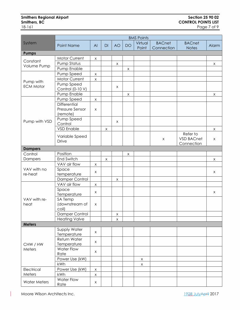
Smithers Regional Airport Section 25 90 02Smithers, BC CONTROL POINTS LIST18-161 Page 7 of 9
Moore Wilson Architects Inc. 1928 JulyApril 2017
BMS PointsSystem Point Name AI DI AO DO Virtual
PointBACnet
ConnectionBACnet Notes Alarm
PumpsMotor Current x Pump Status x xConstant
Volume PumpPump Enable x Pump Speed x Motor Current x Pump Speed Control (0-10 V) x
Pump with ECM Motor
Pump Enable x xPump Speed x Differential Pressure Sensor (remote)
x
Pump Speed Control x
VSD Enable x x
Pump with VSD
Variable Speed Drive x
Refer to VSD BACnet Connection
x
DampersPosition x Control
Dampers End Switch x xVAV air flow x Space temperature x xVAV with no
re‐heatDamper Control x VAV air flow x Space Temperature x x
SA Temp (downstream of coil)
x
Damper Control x
VAV with re-heat
Heating Valve x Meters
Supply Water Temperature x
Return Water Temperature x
Water Flow Rate x
Power Use (kW) x
CHW / HW Meters
kWh x Power Use (kW) x Electrical
Meters kWh x
Water Meters Water Flow Rate x

Smithers Regional Airport Section 25 90 02Smithers, BC CONTROL POINTS LIST18-161 Page 8 of 9
Moore Wilson Architects Inc. 1928 JulyApril 2017
BMS PointsSystem Point Name AI DI AO DO Virtual
PointBACnet
ConnectionBACnet Notes Alarm
Heat Trace Status x Heat Trace Common alarm x x
Domestic Hot Water Tanks
Domestic Hot Water Tanks (DHWT-1, 2, 3)
Status (Current Transducer) x x
Expansion Tanks
Expansion Tanks Pressure Transmitter x x
Heat Exchangers
Load Side Flow x xSupply Side Flow x
Load S/R Pressure (x2) x
Supply S/R Pressure (x2)
Load S/R Temperature (x2)
x
Supply S/R Temperature (x2)
Plate & Frame Heat Exchanger(HX-1, HX-2)
Differential Pressure Transducer (x2)
x
Heaters Space temperature sensor
x x
Fan Status x x
Unit Heater (UH-1)
Heating Valve x Supply air temperature sensor
x x
Common alarm x
Duct Heater (DH-1)
Heating Valve x Space temperature sensor
x xPerimeter Radiation (RAD-1 to 8) Heating Valve
(Control) x

Smithers Regional Airport Section 25 90 02Smithers, BC CONTROL POINTS LIST18-161 Page 9 of 9
Moore Wilson Architects Inc. 1928 JulyApril 2017
BMS PointsSystem Point Name AI DI AO DO Virtual
PointBACnet
ConnectionBACnet Notes Alarm
Variable Frequency Drive
VFD Speed x VFD Current x VFD Speed Control x
VFD Start / Stop x
Variable Frequency Drive (Common to all VFDs)
BACNet Interface
x
1) Frequency Output2) Torque3) Power4) DC Bus Volt5) Output Voltage6) kWh counter7) Run time8) Last Fault9) Hand/Auto10) Run / Stop11) Fault12) TBD13) TBD14) TBD15) TBD
x
Misc. Outdoor Air Dry Bulb Temperature
x
Outdoor Relative Humidity
x Global
Outdoor CO2 level x
END OF SECTION
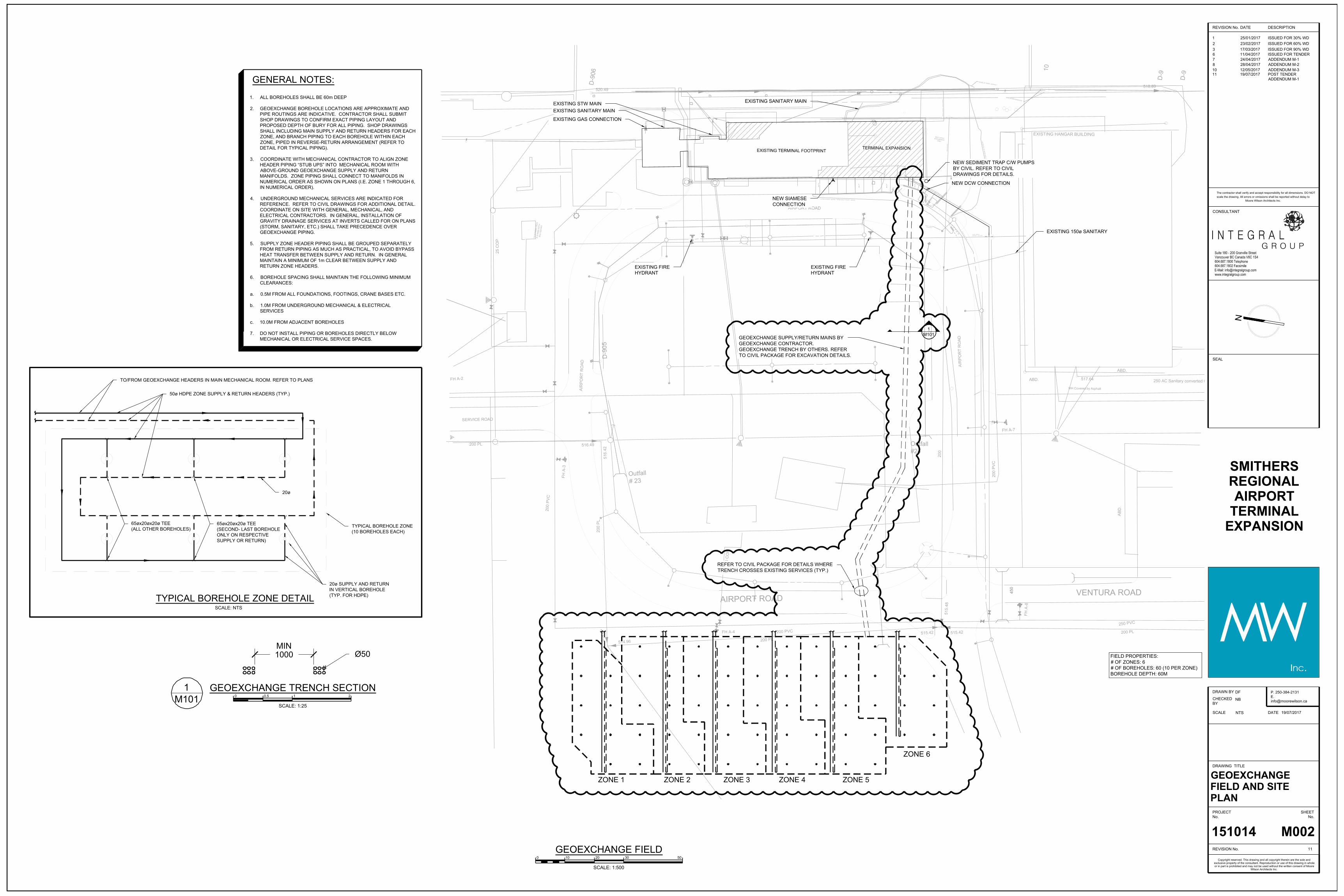
ZONE 2 ZONE 3 ZONE 4 ZONE 5
ZONE 6
FIELD PROPERTIES:# OF ZONES: 6# OF BOREHOLES: 60 (10 PER ZONE)BOREHOLE DEPTH: 60M
NEW DCW CONNECTION
NEW SEDIMENT TRAP C/W PUMPSBY CIVIL. REFER TO CIVILDRAWINGS FOR DETAILS.
TYPICAL BOREHOLE ZONE DETAILSCALE: NTS
TO/FROM GEOEXCHANGE HEADERS IN MAIN MECHANICAL ROOM. REFER TO PLANS
50ø HDPE ZONE SUPPLY & RETURN HEADERS (TYP.)
20ø
20ø SUPPLY AND RETURNIN VERTICAL BOREHOLE(TYP. FOR HDPE)
65øx20øx20ø TEE(SECOND- LAST BOREHOLEONLY ON RESPECTIVESUPPLY OR RETURN)
65øx20øx20ø TEE(ALL OTHER BOREHOLES) TYPICAL BOREHOLE ZONE
(10 BOREHOLES EACH)
GENERAL NOTES:
1. ALL BOREHOLES SHALL BE 60m DEEP
2. GEOEXCHANGE BOREHOLE LOCATIONS ARE APPROXIMATE ANDPIPE ROUTINGS ARE INDICATIVE. CONTRACTOR SHALL SUBMITSHOP DRAWINGS TO CONFIRM EXACT PIPING LAYOUT ANDPROPOSED DEPTH OF BURY FOR ALL PIPING. SHOP DRAWINGSSHALL INCLUDING MAIN SUPPLY AND RETURN HEADERS FOR EACHZONE, AND BRANCH PIPING TO EACH BOREHOLE WITHIN EACHZONE, PIPED IN REVERSE-RETURN ARRANGEMENT (REFER TODETAIL FOR TYPICAL PIPING).
3. COORDINATE WITH MECHANICAL CONTRACTOR TO ALIGN ZONEHEADER PIPING “STUB UPS” INTO MECHANICAL ROOM WITHABOVE-GROUND GEOEXCHANGE SUPPLY AND RETURNMANIFOLDS. ZONE PIPING SHALL CONNECT TO MANIFOLDS INNUMERICAL ORDER AS SHOWN ON PLANS (I.E. ZONE 1 THROUGH 6,IN NUMERICAL ORDER).
4. UNDERGROUND MECHANICAL SERVICES ARE INDICATED FORREFERENCE. REFER TO CIVIL DRAWINGS FOR ADDITIONAL DETAIL.COORDINATE ON SITE WITH GENERAL, MECHANICAL, ANDELECTRICAL CONTRACTORS. IN GENERAL, INSTALLATION OFGRAVITY DRAINAGE SERVICES AT INVERTS CALLED FOR ON PLANS(STORM, SANITARY, ETC.) SHALL TAKE PRECEDENCE OVERGEOEXCHANGE PIPING.
5. SUPPLY ZONE HEADER PIPING SHALL BE GROUPED SEPARATELYFROM RETURN PIPING AS MUCH AS PRACTICAL, TO AVOID BYPASSHEAT TRANSFER BETWEEN SUPPLY AND RETURN. IN GENERALMAINTAIN A MINIMUM OF 1m CLEAR BETWEEN SUPPLY ANDRETURN ZONE HEADERS.
6. BOREHOLE SPACING SHALL MAINTAIN THE FOLLOWING MINIMUMCLEARANCES:
a. 0.5M FROM ALL FOUNDATIONS, FOOTINGS, CRANE BASES ETC.
b. 1.0M FROM UNDERGROUND MECHANICAL & ELECTRICAL SERVICES
c. 10.0M FROM ADJACENT BOREHOLES
7. DO NOT INSTALL PIPING OR BOREHOLES DIRECTLY BELOWMECHANICAL OR ELECTRICAL SERVICE SPACES.
EXISTING SANITARY MAINEXISTING STW MAIN
EXISTING GAS CONNECTION
EXISTING SANITARY MAIN
NEW SIAMESECONNECTION
EXISTING FIREHYDRANT
EXISTING FIREHYDRANT
M1011
GEOEXCHANGE SUPPLY/RETURN MAINS BYGEOEXCHANGE CONTRACTOR.GEOEXCHANGE TRENCH BY OTHERS. REFERTO CIVIL PACKAGE FOR EXCAVATION DETAILS.
EXISTING 150ø SANITARY
ZONE 1
REFER TO CIVIL PACKAGE FOR DETAILS WHERETRENCH CROSSES EXISTING SERVICES (TYP.)
1000 Ø50MIN
REVISION No.
PROJECTNo.
DRAWN BY
DATE
CHECKEDBY
DRAWING TITLE
SHEETNo.
REVISION No.
SCALE
CONSULTANT
SEAL
DATE DESCRIPTION
NB
DF
19/07/2017
25/01/2017 ISSUED FOR 30% WD1
11
23/02/2017 ISSUED FOR 60% WD2
scale the drawing. All errors or omissions shall be reported without delay to
SMITHERSREGIONALAIRPORT
TERMINALEXPANSION
151014
Copyright reserved. This drawing and all copyright therein are the sole andexclusive property of the consultant. Reproduction or use of this drawing in wholeor in part is prohibited and may not be used without the written consent of Moore
Wilson Architects Inc.
The contractor shall verify and accept responsibility for all dimensions. DO NOT
Moore Wilson Architects Inc.
17/03/2017 ISSUED FOR 90% WD311/04/2017 ISSUED FOR TENDER624/04/2017 ADDENDUM M-1728/04/2017 ADDENDUM M-2812/05/2017 ADDENDUM M-31019/07/2017 POST TENDER
ADDENDUM M-111
NTS
SCALE: 1:500
3010 20 500
GEOEXCHANGE FIELD
M002
GEOEXCHANGEFIELD AND SITEPLAN
M1011
SCALE: 1:25
1 20 0.5
GEOEXCHANGE TRENCH SECTION
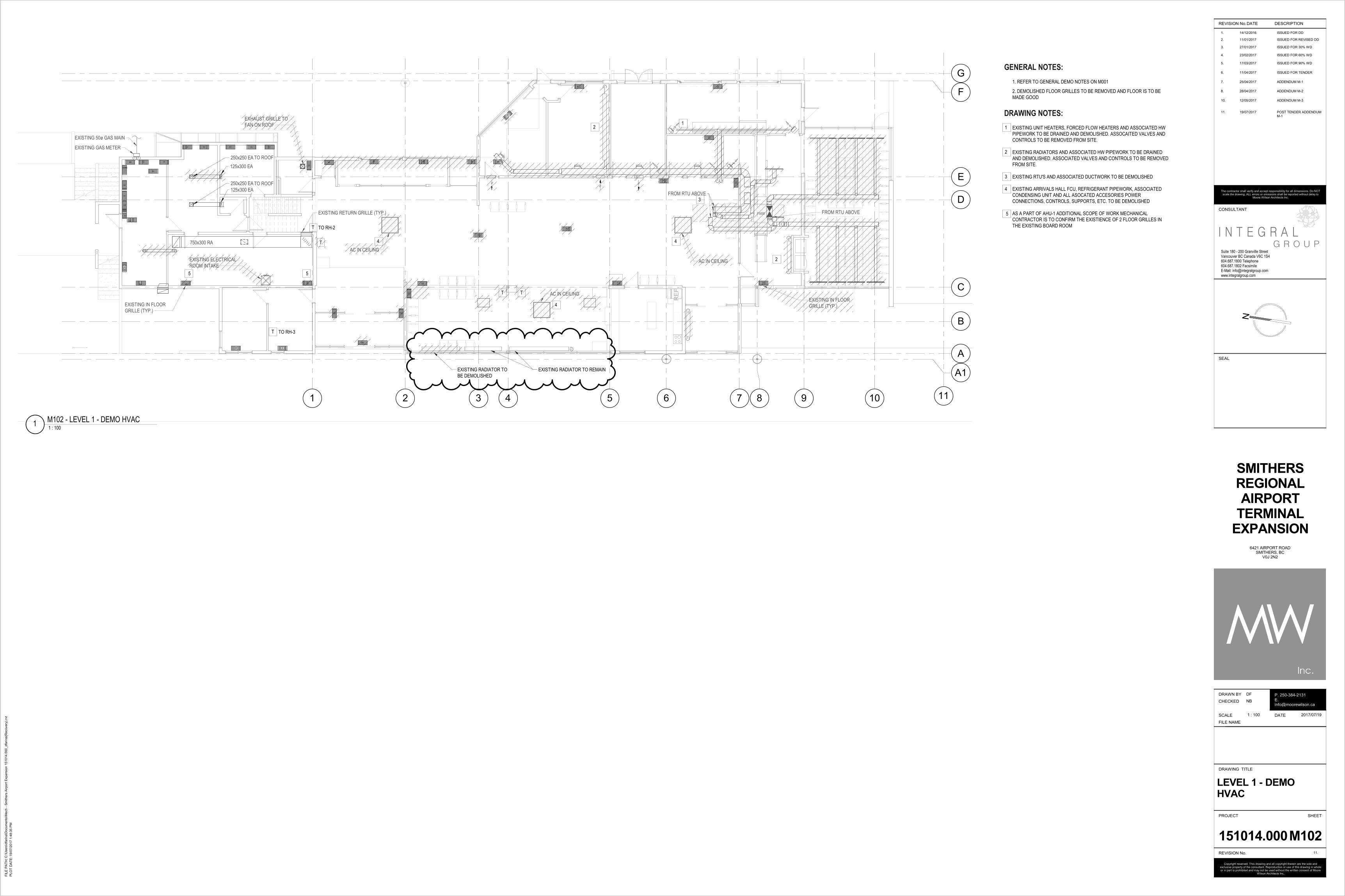
RE
F.
1 2 3 4 5 6 7 8 9
B
F
A
G
D
E
10 11
C
250x250 EA
125x300 EA
250x250 EA
125x300 EA
TO ROOF
TO ROOF
EXHAUST GRILLE TO
FAN ON ROOF
EXISTING IN FLOOR
GRILLE (TYP.)
EXISTING IN FLOOR
GRILLE (TYP.)
FROM RTU ABOVE
FROM RTU ABOVE
AC IN CEILING
AC IN CEILING
A1EXISTING RADIATOR TO REMAIN
T T
T
T
EXISTING 50ø GAS MAIN
EXISTING GAS METER
750x300 RA
EXISTING RETURN GRILLE (TYP.)
EXISTING ELECTRICAL
ROOM INTAKE
T TO RH-3
TO RH-2
AC IN CEILING
EXISTING RADIATOR TO
BE DEMOLISHED
Suite 180 - 200 Granville StreetVancouver BC Canada V6C 1S4604.687.1800 Telephone604.687.1802 FacsimileE-Mail: [email protected]
G R O U PI N T E G R A L
N
FIL
E P
AT
H:
PLO
T D
AT
E:
REVISION No.
Copyright reserved. This drawing and all copyright therein are the sole and exclusive property of the consultant. Reproduction or use of this drawing in whole or in part is prohibited and may not be used without the written consent of Moore
Wilson Architects Inc.
PROJECT
DRAWN BY
DATE
CHECKED
DRAWING TITLE
SHEET
REVISION No.
FILE NAME
SCALE
CONSULTANT
SEAL
P. 250-384-2131E. [email protected]
The contractor shall verify and accept responsibility for all dimensions. Do NOT scale the drawing. ALL errors or omissions shall be reported without delay to
Moore Wilson Architects Inc.
DATE DESCRIPTION
1. 14/12/2016 ISSUED FOR DD
11.
2. 11/01/2017 ISSUED FOR REVISED DD
3. 27/01/2017 ISSUED FOR 30% WD
4. 23/02/2017 ISSUED FOR 60% WD
5. 17/03/2017 ISSUED FOR 90% WD
6. 11/04/2017 ISSUED FOR TENDER
7. 25/04/2017 ADDENDUM M-1
8. 28/04/2017 ADDENDUM M-2
10. 12/05/2017 ADDENDUM M-3
11. 19/07/2017 POST TENDER ADDENDUM M-1
C:\
Users
\dfa
rina\D
ocum
ents
\Mech -
Sm
ithers
Air
port
Expansio
n 1
51014.0
00_dfa
rina(R
ecovery
).rv
t
19/0
7/2
017 1
:48:3
5 P
M
1 : 100
151014.000
DF
NB
SMITHERS
REGIONAL
AIRPORT
TERMINAL
EXPANSION
LEVEL 1 - DEMO
HVAC
6421 AIRPORT ROADSMITHERS, BC
V0J 2N2
M102
2017/07/19
1 : 1001
M102 - LEVEL 1 - DEMO HVAC
GENERAL NOTES:
1. REFER TO GENERAL DEMO NOTES ON M001
DRAWING NOTES:
EXISTING UNIT HEATERS, FORCED FLOW HEATERS AND ASSOCIATED HW
PIPEWORK TO BE DRAINED AND DEMOLISHED. ASSOCAITED VALVES AND
CONTROLS TO BE REMOVED FROM SITE.
EXISTING RADIATORS AND ASSOCIATED HW PIPEWORK TO BE DRAINED
AND DEMOLISHED. ASSOCIATED VALVES AND CONTROLS TO BE REMOVED
FROM SITE.
EXISTING RTU'S AND ASSOCIATED DUCTWORK TO BE DEMOLISHED
EXISTING ARRIVALS HALL FCU, REFRIGERANT PIPEWORK, ASSOCIATED
CONDENSING UNIT AND ALL ASOCATED ACCESORIES POWER
CONNECTIONS, CONTROLS, SUPPORTS, ETC. TO BE DEMOLISHED
AS A PART OF AHU-1 ADDITIONAL SCOPE OF WORK MECHANICAL
CONTRACTOR IS TO CONFIRM THE EXISTIENCE OF 2 FLOOR GRILLES IN
THE EXISTING BOARD ROOM
1
2
3
1 2
2
3
4
4 4
2. DEMOLISHED FLOOR GRILLES TO BE REMOVED AND FLOOR IS TO BE
MADE GOOD
5
5 5
4

RE
F.
1 2 3 4 5 6 7 8 9
B
F
A
G
D
E
10
C
RAD-1
HWS/R PIPING FROM BELOW FOR OFFICE RADIATORS
RAD-3 RAD-4
RAD-4RAD-3
RAD-4
TO AHU-3 ON ROOF
HWS/R &CHWS/R TO
RUN IN WALL
RE
FE
R T
O 2
/ M
202
RAD-4RAD-4
AC-1RAD-6 RAD-6 RAD-1
12ø STACKED HWS/R
TO/FROM BELOW
EX. MEETING RM.
CCC
EX. MGR RM.
BBB
EX. BOARDROOM
DDD
EX. ADMIN
EEE
EX. OFFICE SC
FF
EX. WC
JJ
WC
104
EX. OFFICE SC.
II
EX. OFFICE SC.
REX. ARRI. VEST.
101
ARRIVALS HALL
102
BAGGAGE CLAIM
103
BAGGAGE DROP
106
DEPARTURES
HALL
113
CHECK IN AREA
114
OFFICE
115
OFFICE
116
OFFICE
117
BOARDING QUEUE
121
PBS
123
WC W
118EX. DEP. VEST.
112
WC M
119
JAN.
120
LEASE SP.
108 LOUNGE
110
A1
32 HWR
32 HWS
38 CHWS38 CHWR
38 CHWS
38 CHWR
32 HWR32 HWS
ARRI. VEST.
107OVS. VEST.
105
T
T
T
T T
T T
T
T
T
EXISTING GAS METER
12ø HWS FROM
BELOW
RAD-2RAD-8
3
M212
EXISTING RADIATOR
B
F
A
G
D
E
10 11 12 13 14 15
C
RAD-1RAD-1RAD-1RAD-2RAD-1
RE
FE
R T
O 1
/ M
202
UH-1
UH-1
AC-1
T
RAD-1
RAD-1
RAD-5
RAD-5
PBS
123
BOARDING
LOUNGE
124
BOARD. VEST.
125
WC W
128WC
127
WC M
129
BAGGAGE MAKEUP
130
BAGG. VEST.
131
A1
T T
T
T
RAD-7 @16
EF-1
19 HWR
19 HWS
19 HWR
19 HWS
AIR CURTAIN TO BE INSTALLED BELOW
ROLLER DOOR. BRACING ON EITHER
SIDE OF THE ROLLING DOOR TO ATTACH
THE UNIT TO THE CEILING. TO BE COORDINATED
WITH ARCHITECTURAL.
19 HWR
SF-1
DH-1
AC-1
(TYP.)
(TYP.)25 HWR25 HWS
12 HWR12 HWS
20 HWR20 HWS
Suite 180 - 200 Granville StreetVancouver BC Canada V6C 1S4604.687.1800 Telephone604.687.1802 FacsimileE-Mail: [email protected]
G R O U PI N T E G R A L
N
FIL
E P
AT
H:
PLO
T D
AT
E:
REVISION No.
Copyright reserved. This drawing and all copyright therein are the sole and exclusive property of the consultant. Reproduction or use of this drawing in whole or in part is prohibited and may not be used without the written consent of Moore
Wilson Architects Inc.
PROJECT
DRAWN BY
DATE
CHECKED
DRAWING TITLE
SHEET
REVISION No.
FILE NAME
SCALE
CONSULTANT
SEAL
P. 250-384-2131E. [email protected]
The contractor shall verify and accept responsibility for all dimensions. Do NOT scale the drawing. ALL errors or omissions shall be reported without delay to
Moore Wilson Architects Inc.
DATE DESCRIPTION
1. 14/12/2016 ISSUED FOR DD
11.
2. 11/01/2017 ISSUED FOR REVISED DD
3. 27/01/2017 ISSUED FOR 30% WD
4. 23/02/2017 ISSUED FOR 60% WD
5. 17/03/2017 ISSUED FOR 90% WD
6. 11/04/2017 ISSUED FOR TENDER
7. 25/04/2017 ADDENDUM M-1
8. 28/04/2017 ADDENDUM M-2
10. 12/05/2017 ADDENDUM M-3
11. 19/07/2017 POST TENDER ADDENDUM M-1
C:\
Users
\dfa
rina\D
ocum
ents
\Mech -
Sm
ithers
Air
port
Expansio
n 1
51014.0
00_dfa
rina(R
ecovery
).rv
t
19/0
7/2
017 1
:48:3
9 P
M
1 : 100
151014.000
DF
NB
SMITHERS
REGIONAL
AIRPORT
TERMINAL
EXPANSION
LEVEL 1 -
HYDRONICS
6421 AIRPORT ROADSMITHERS, BC
V0J 2N2
M202
2017/07/19
1 : 1001
M202 - LEVEL 1 - HYDRONICS - NORTH
1 : 1002
M202 - LEVEL 1 - HYDRONICS - SOUTH
GENERAL NOTES:
1. ALL RADIATORS TO BE C/W THERMOSTAT RADIATOR VALVE AND
ISOLATION VALVE.
2. ALL FORCED FLOW HEATERS TO BE C/W ISOALTION VALVES AND
THERMOSTAT CONTROL.
3. SIZES OF EXISTING PIPEWORK INCLUDED ON M102.
4. TEMPERATURE SENSOR TO BE INSTALLED AT 1500 AFFL.
DRAWING NOTES:
REFER TO MECHANICAL DETAIL M502 FOR UNIT HEATER INSTALATION DETAIL
PIPING SHOWN AT THIS LOCATION FOR CLARITY. PIPES TO RUN UNDER
AHU-2 AND RISE INTO PIPE VESTIBULE ON AHU-2 FOR CONNECTION TO
COILS. PROVIDE ISOLATION VALVES AND DRAIN CONNECTIONS ON PIPING
DIRECTLY BELOW UNIT.
CHW AND HW PIPING TO RISE UP INTO AHU-3 PIPING VESTIBULE.
PROVIDE ISOLATION VALVES AND DRAIN CONNECTIONS ON PIPING
DIRECTLY BELOW UNIT.
1
1
1
2
2
3
3

M
M
M
1 2 3 4 5 6 7 8 9
B
F
A
G
D
E
10
C
250X100 E/A FROM
JANITOR CLOSET
RE
FE
R T
O 2
/ M
211
S-2
600x600
60
200ø DUCT UP TO BOARDING
LOUNGE DISPLACMENT
DIFFUSER ABOVE (TYP.)
200ø SA
M241
2
250x250 SA
600x250 SA
125ø SA
125ø SA
100ø SA
200ø SA
125ø SA
250x150 SA
125ø SA
300x200 SA
400x200 SA
(TYP.)
(TYP.)
350x250 SA
250x250 SA
EX. ELEC. RM.
005
EX. CRAWL
SPACE
LL
EX. COMM. RM.
004-1
EX. STOR
TT
Office
V
A1
550x250 SA
S-4
200x100
3@
498550X250 SA FROM AHU-3
550X250 SA
TO CAFE
400x200 EA
400X150 E/A FROM
WASHROOMS
20 L/S CRAWLSPACE
VENTILATION (TYP.)
20 L/S CRAWLSPACE
VENTILATION (TYP.)
EF-2
550x550 SA750x450 SA
MECHANICAL CONTRACTOR TO
COORDINATE FINAL LOCATION
OF THE EXHAUST FAN WITH
ELECTRICAL CONTRACTOR
AND ELECTRICAL ROOM EQUIPMENT
B
F
A
G
D
E
10 11 12 13 14 15
C
450x400 SA
400x400 SA
400x400 SA
M242
1
RE
FE
R T
O 1
/ M
211
400x200 EA
200ø DUCT UP TO BOARDING
LOUNGE DISPLACMENT
DIFFUSER ABOVE (TYP.)
600x650 SA
550x400 SA
DF
DF
CRAWL SPACE
PP
CRAWL SPACE
OO
A1
1500x300 EA
DF
100ø S/A DUCT TO
LUGGAGE CONVEYOR
100ø S/A DUCT TO
LUGGAGE CONVEYOR
R-1
200x100
80
M242
3
450x200 EA
900x450 EA
Suite 180 - 200 Granville StreetVancouver BC Canada V6C 1S4604.687.1800 Telephone604.687.1802 FacsimileE-Mail: [email protected]
G R O U PI N T E G R A L
N
FIL
E P
AT
H:
PLO
T D
AT
E:
REVISION No.
Copyright reserved. This drawing and all copyright therein are the sole and exclusive property of the consultant. Reproduction or use of this drawing in whole or in part is prohibited and may not be used without the written consent of Moore
Wilson Architects Inc.
PROJECT
DRAWN BY
DATE
CHECKED
DRAWING TITLE
SHEET
REVISION No.
FILE NAME
SCALE
CONSULTANT
SEAL
P. 250-384-2131E. [email protected]
The contractor shall verify and accept responsibility for all dimensions. Do NOT scale the drawing. ALL errors or omissions shall be reported without delay to
Moore Wilson Architects Inc.
DATE DESCRIPTION
1. 14/12/2016 ISSUED FOR DD
11.
2. 11/01/2017 ISSUED FOR REVISED DD
3. 27/01/2017 ISSUED FOR 30% WD
4. 23/02/2017 ISSUED FOR 60% WD
5. 17/03/2017 ISSUED FOR 90% WD
6. 11/04/2017 ISSUED FOR TENDER
7. 25/04/2017 ADDENDUM M-1
8. 28/04/2017 ADDENDUM M-2
10. 12/05/2017 ADDENDUM M-3
11. 19/07/2017 POST TENDER ADDENDUM M-1
C:\
Users
\dfa
rina\D
ocum
ents
\Mech -
Sm
ithers
Air
port
Expansio
n 1
51014.0
00_dfa
rina(R
ecovery
).rv
t
19/0
7/2
017 1
:48:4
1 P
M
1 : 100
151014.000
DF
NB
SMITHERS
REGIONAL
AIRPORT
TERMINAL
EXPANSION
CRAWLSPACE - HVAC
6421 AIRPORT ROADSMITHERS, BC
V0J 2N2
M211
2017/07/19
1 : 1001
M211 - CRAWL SPACE - HVAC - NORTH
1 : 1002
M211 - CRAWL SPACE - HVAC - SOUTH
1
GENERAL NOTES:
1. ALL DUCTWORK PENETRATING FIRE RATED WALLS TO BE EQUIPPED
WITH A FIRE DAMPER AND ALL OTHER SERVICES MUST BE FIRE STOPPED
IN ACCORDANCE WITH THE FIRE ASSEMBLY RATING.
1

RE
F.
1 2 3 4 5 6 7 8 9
B
F
A
G
D
E
10
C
250X100 E/A DOWN
TO BELOW
S-2
600x600
4@
60
AHU-3 ON ROOF
EXISTING SUPPLY AIR FLOOR
GRILLES FROM DUCTS IN
CRAWLSPACE BASEMENT BELOW
RE
FE
R T
O 2
/ M
212
S-2
600x600
2@
35
S-2
600x600
2@
80
200x150 SA
250x
250
SA
T
S-3
300x900
2@
160
S-2
600x600
65
E-3
600x600
50
E-2
300x150
4@
50
EX. MEETING RM.
CCC
EX. MGR RM.
BBB
EX. ADMIN
EEE
EX. OFFICE SC
FF
EX. BOARDROOM
DDD
WC
104
OVS. VEST.
105
BAGGAGE CLAIM
103
ARRIVALS HALL
102
CHECK IN AREA
114
DEPARTURES
HALL
113
EX. DEP. VEST.
112
LOUNGE
110
LEASE SP.
108
OFFICE
117
OFFICE
115
PBS
123
BOARDING QUEUE
121
WC M
119WC W
118
JAN.
120
ARRI. VEST.
107
EX. OFFICE SC.
R
EX. OFFICE SC.
II
EX. ARRI. VEST.
101
BAGGAGE DROP
106
A1
S-2
600x600
4@
145
VAV-1.4
R-2
600x600
500
R-2
600x600
2@
500
R-2
600x600
2@
500
T
T
T
T
E-2
250x500
50
S-2
600x600
3@
60
550x250 SA
200ø SA (TYP.)
OFFICE
116
T1
150x400 EA
750x300 RA
250x250 EA
S-4
450x250
2@
190
350x300 SA
VAV-1.3VAV-1.2
T1T1
R-2
600x600
2@
35
T
550X250 FROM
BELOW
150X400 FROM
BELOW
550X300 TO BELOW
200x150 SA
S-5
300x150
4@
25
EX. WC
JJ
L-1
1350x450
1500
450x750 SA450x1350 SA
3
M212
350x350 SA
250x200 SA
300x300 SA
400x350 SA
400x400 SA
VAV-1.1
450x450 SA
200x150 SA
200x200 SA
200x150 SA
200x200 SA
250x250 SA
550X550 S/A FROM AHU-3
750X400 R/A TO AHU-3
B
F
A
G
D
E
10 11 12 13 14 15
CDISPLACEMENT GRILLE
AT LOW LEVEL AROUND
COLUMN (TYP.).
450X200 E/A DOWN TO BELOW
E-1
300x150
6@
50
HIGH LEVEL AIR INTAKE
FOR BAGGAGE ROOM
RE
FE
R T
O 1
/ M
212
EF-1
100ø S/A DUCTED TO
BAGGAGE CAROUSEL
(10 L/S)
L-1
900x300
460
250x100 EA
S-3
300x900
160
S-3
300x900
16@
110
S-3
300x900
110
BOARDING
LOUNGE
124
PBS
123
BAGGAGE MAKEUP
130
WC M
129
WC W
128
WC
127
BOARD. VEST.
125
A1L-1
900x300
460
R-1
1500x400
2100
DH-1
UH-1
UH-1
AC-1
FILTER
S-3
300x900
110
S-3
300x900
160
O T
SF-1
1500X300 E/A
FROM BELOW
750X500 OA/EA TO/FROM BELOW
300x300 EA
300ø OA
300X300 EA DUCTED DOWN
150ø BOILER COMBINED
COAXIAL DUCT FROM
BELOW
FIRE RATED BULKHEAD TO ENCLOSE
BOILER COMBINED DUCTWORK
600X650 E/A
TO ABOVE
600X650 O/A
FROM ABOVE
U/S ROOF104000
T/O ROOF104905
6 7 8
AHU-3750x400 RA
550x550 SA
Suite 180 - 200 Granville StreetVancouver BC Canada V6C 1S4604.687.1800 Telephone604.687.1802 FacsimileE-Mail: [email protected]
G R O U PI N T E G R A L
N
FIL
E P
AT
H:
PLO
T D
AT
E:
REVISION No.
Copyright reserved. This drawing and all copyright therein are the sole and exclusive property of the consultant. Reproduction or use of this drawing in whole or in part is prohibited and may not be used without the written consent of Moore
Wilson Architects Inc.
PROJECT
DRAWN BY
DATE
CHECKED
DRAWING TITLE
SHEET
REVISION No.
FILE NAME
SCALE
CONSULTANT
SEAL
P. 250-384-2131E. [email protected]
The contractor shall verify and accept responsibility for all dimensions. Do NOT scale the drawing. ALL errors or omissions shall be reported without delay to
Moore Wilson Architects Inc.
DATE DESCRIPTION
1. 14/12/2016 ISSUED FOR DD
11.
2. 11/01/2017 ISSUED FOR REVISED DD
3. 27/01/2017 ISSUED FOR 30% WD
4. 23/02/2017 ISSUED FOR 60% WD
5. 17/03/2017 ISSUED FOR 90% WD
6. 11/04/2017 ISSUED FOR TENDER
7. 25/04/2017 ADDENDUM M-1
8. 28/04/2017 ADDENDUM M-2
10. 12/05/2017 ADDENDUM M-3
11. 19/07/2017 POST TENDER ADDENDUM M-1
C:\
Users
\dfa
rina\D
ocum
ents
\Mech -
Sm
ithers
Air
port
Expansio
n 1
51014.0
00_dfa
rina(R
ecovery
).rv
t
19/0
7/2
017 1
:48:4
3 P
M
As indicated
151014.000
DF
NB
SMITHERS
REGIONAL
AIRPORT
TERMINAL
EXPANSION
LEVEL 1 - HVAC
6421 AIRPORT ROADSMITHERS, BC
V0J 2N2
M212
2017/07/19
1 : 1001
M212 - LEVEL 1 - HVAC - NORTH
1 : 1002
M212 - LEVEL 1 - HVAC - SOUTH
DRAWING NOTES:
ALL PENETRATIONS THROUGH FIRE RATED WALLS MUST BE FIRE RATED
IN LINE WITH ARCHITECTS SPECIFICATIONS.
PROVIDE FIRE DAMPERS AT ALL DUCT PENETRATIONS THROUGH FLOOR
OF BAGGAGE MAKEUP ROOM / CEILING OF MECHANICAL ROOM
1
GENERAL NOTES:
1. SIZES OF EXISTING DUCTWORK INCLUDED ON M102.
2
2
2
1 : 483
AHU-3 SECTION
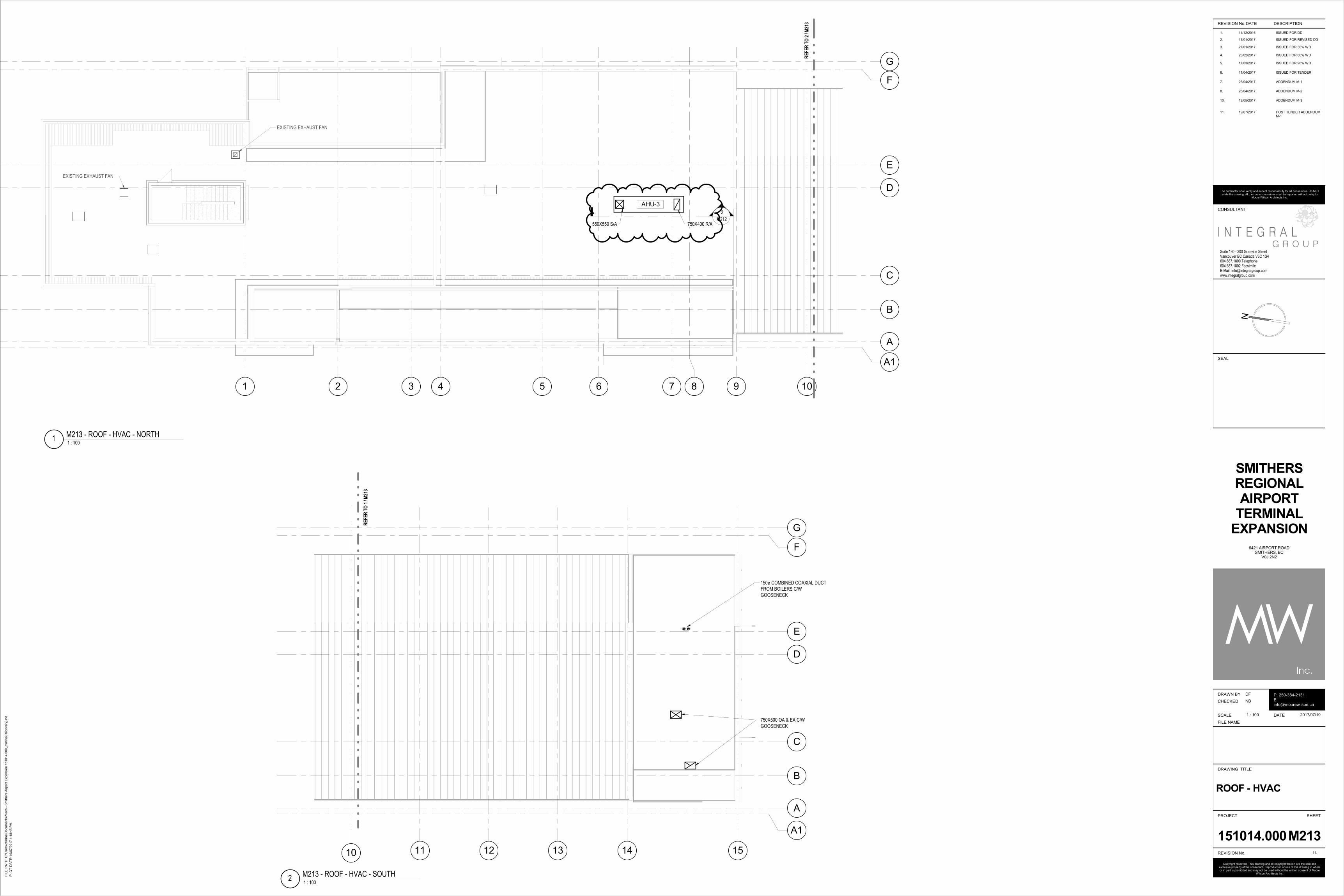
1 2 3 4 5 6 7 8 9
B
F
A
G
D
E
10
C
RE
FE
R T
O 2
/ M
213
A1
EXISTING EXHAUST FAN
EXISTING EXHAUST FAN
3
M212
AHU-3
550X550 S/A 750X400 R/A
B
F
A
G
D
E
10 11 12 13 14 15
C
RE
FE
R T
O 1
/ M
213
A1
750X500 OA & EA C/W
GOOSENECK
150ø COMBINED COAXIAL DUCT
FROM BOILERS C/W
GOOSENECK
Suite 180 - 200 Granville StreetVancouver BC Canada V6C 1S4604.687.1800 Telephone604.687.1802 FacsimileE-Mail: [email protected]
G R O U PI N T E G R A L
N
FIL
E P
AT
H:
PLO
T D
AT
E:
REVISION No.
Copyright reserved. This drawing and all copyright therein are the sole and exclusive property of the consultant. Reproduction or use of this drawing in whole or in part is prohibited and may not be used without the written consent of Moore
Wilson Architects Inc.
PROJECT
DRAWN BY
DATE
CHECKED
DRAWING TITLE
SHEET
REVISION No.
FILE NAME
SCALE
CONSULTANT
SEAL
P. 250-384-2131E. [email protected]
The contractor shall verify and accept responsibility for all dimensions. Do NOT scale the drawing. ALL errors or omissions shall be reported without delay to
Moore Wilson Architects Inc.
DATE DESCRIPTION
1. 14/12/2016 ISSUED FOR DD
11.
2. 11/01/2017 ISSUED FOR REVISED DD
3. 27/01/2017 ISSUED FOR 30% WD
4. 23/02/2017 ISSUED FOR 60% WD
5. 17/03/2017 ISSUED FOR 90% WD
6. 11/04/2017 ISSUED FOR TENDER
7. 25/04/2017 ADDENDUM M-1
8. 28/04/2017 ADDENDUM M-2
10. 12/05/2017 ADDENDUM M-3
11. 19/07/2017 POST TENDER ADDENDUM M-1
C:\
Users
\dfa
rina\D
ocum
ents
\Mech -
Sm
ithers
Air
port
Expansio
n 1
51014.0
00_dfa
rina(R
ecovery
).rv
t
19/0
7/2
017 1
:48:4
5 P
M
1 : 100
151014.000
DF
NB
SMITHERS
REGIONAL
AIRPORT
TERMINAL
EXPANSION
ROOF - HVAC
6421 AIRPORT ROADSMITHERS, BC
V0J 2N2
M213
2017/07/19
1 : 1001
M213 - ROOF - HVAC - NORTH
1 : 1002
M213 - ROOF - HVAC - SOUTH

AIR HANDLING UNIT SCHEDULETag No. AHU-1 AHU-3
MANUFACTURER TRANE OLYMPIC
MODEL NUMBER CSAA003UA OAH008GDGM
LOCATION EXISTING MECH ROOM ROOF
SERVICE EXISTING OFFICES DEPARTURES/ARRIVALS
WEIGHT KG 415 1550
DIMENSIONS (LXHXW) MM 2200X825X800 4750X8251150X1100
VOLTAGE/PHASE V/Ph 208/3 575/3
FAN SUPPLY AIR:
FLOW L/S 700 1700
EXTERNAL STATIC PA 185 190
MOTOR HP 3 5
MIN O/A 200 1010
COOLING COIL:
SENSIBLE KW 8.2 26.5
LATENT KW
TOTAL KW 10.5 34
WATER SIDE:
GLYCOL CONTENT % 25 25
EWT/LWT °C 8/14 8/14
FLOW L/S 0.44 1.4
AIR SIDE:
EAT [WB/DB] °C 22/17 24/18.5
LAT [WB/DB] 12.5/12.4
WATER PRESSURE DROP KPA 6.6 30
AIR PRESSURE DROP PA 250 112
HEATING COIL:
TOTAL KW 81.5
WATER SIDE:
GLYCOL CONTENT % 25
EWT/LWT °C 70/50
FLOW L/S 1
AIR SIDE:
EAT/LAT °C-5/32
FILTER STAGES -4" MERV 13-2" MERV 8
-300mm" MERV 11-MERV 15 CARBON FILTER
WATER PRESSURE DROP KPA 28.7AIR PRESSURE DROP PA 52
Notes: COOLING ONLY. FRONT SADISCHARGE, BOTTOM RAINTAKE, TOP OA INTAKE
(REFER TO DRAWINGS). ALLACCESS PANELS ARE TO BEON THE LEFT SIDE OF THE
UNIT.
EXTERIOR AHU C/W PIPINGVESTIBULE & VSD IN NEMA3R ENCLOSURE. BOTTOMSA DISCHARGE, BOTTOM
RA INTAKE, LEFT OAINTAKE, RIGHT RELIEFDISCHARGE (REFER TO
DRAWINGS). ALL ACCESSPANELS ARE TO BE ON THE
LEFT SIDE OF THE UNIT.COIL CONNECTIONS ANDPIPING ENCLOSURE TO BE
ON LEFT HAND SIDE OFUNIT. DIRECT DRIVE FAN.
WATER SOURCE HEAT PUMP SCHEDULETAG NO. WWHP-1+2MANUFACTURER MultistackMODEL NUMBER MS20X6NOMINAL KW 70LOAD SIDE MEDIUM WATERSOURCE SIDE MEDIUM 25% GLYCOLLOAD SIDE WATER FLOW RATE (L/S) 3.4CONDENSER WATER FLOR RATE (l/s) 2.57LOAD SIDE WATER PRESSURE (KPA) 9SOURCE SIDE WATER PRESSURE (KPA) 92VOLTAGE/PHASE 575/3MCA/MOP 36/60OPERATING WEIGHT (KG) 544 KGREFRIGERANT TYPE R410A/R134ADIMENSION (L/W/H) 1600x1400x1700COOLING PERFORMANCE
LOAD ENTERING/LEAVING ºC 10.6ºC/5.6ºCSOURCE ENTERING/LEAVING ºC 26.7ºC/35ºCTOTAL CAPACITY (kW) 70kWEER 14.8HEATING PERFORMANCE
HEATING CAPACITY (kW) 70kWLOAD ENTERING/LEAVING ºC 45ºC/40ºCSOURCE ENTERING/LEAVING ºC 5ºC/0ºC
COP 3.3ACCESSORIES
PLUMBING FIXTURE SCHEDULESYMBOL FIXTURE DESCRIPTION Material ACCESSORIES NOTES/COMMEN
TSWC-1 Toilet TOTO CT705ELN 'Floor mounted Flushometer
Toilet', Toilet, white vitreous china, FloorMounted, operates in the range of 4.8 L to 6 L(1.28 US Gal to 1.6 US Gal) per flush, elongatedbowl.
TOTO CT708EV, heavy duty Toilet Seat, solid plastic withantimicrobial surface, open front less cover.TOTO TET2LA, 'EcoPower', Concealed Flushometer for Top Spudtoilet,4.8 L (1.28 US Gal) flush factory set flow.
standard w/c
WC-2 Toilet TOTO CT705ELN 'Floor mounted FlushometerToilet', Toilet, white vitreous china, FloorMounted, operates in the range of 4.8 L to 6 L(1.28 US Gal to 1.6 US Gal) per flush, elongatedbowl.
TOTO CT708EV, heavy duty Toilet Seat, solid plastic withantimicrobial and fire retardant surface, open front with cover.TOTO TET2LA, 'EcoPower', Concealed Flushometer for Top Spudtoilet,4.8 L (1.28 US Gal) flush factory set flow.
barrier-free w/c
UR-1 Urinal TOTO UT445U, 'High Efficiency Washout Urinal',Urinal, vitreous china, operates at 0.5 L (0.125 USGal) per flush Wall Hung.
TOTO TEU2UA 0.125, 'EcoPower', Concealed Flushometer forTop Spud urinal,0.5 L (0.125 US Gal) factory set flow.
barrier-free urinal
LAV-1 Basin Elkay ELUH9 'Asana Stainless Steel Single Bowl'Undermount Bathroom Sink Basin, self-rimming -drop-in.
TOTO TEL105 Series, 'EcoPower', Electronic faucet, 1.9 LPM (0.5GPM) aerator spray outlet.Lawler #TMM-1070, Point Of Use Mechanical Water MixingValve, integral checks.McGuire #155WCC, Offset Open Grid Drain.McGuire #LFH170BVRB, polished brass Faucet Supplies.McGuire #8872CBSAN, P-Trap.McGuire #PW2000WC, 'PROWRAP', Sanitary Covering.
barrier-freelavatory
LAV-2 Basin TOTO LT307 (A) ' commercial wall hung lavatory'wall mounted bathroom sink basin
TOTO TEL105 Series, 'EcoPower', Electronic faucet, 1.9 LPM (0.5GPM) aerator spray outlet.Lawler #TMM-1070, Point Of Use Mechanical Water MixingValve, integral checks. McGuire #8872CBSAN,P-Trap.McGuire #PW2000WC, 'PROWRAP', Sanitary Covering.Jay R. Smith 0700 (Concealed Arms) with 19" arms 0800 (WallSupport Plate).
barrier-freelavatory
LAV-3 Basin Whitehaus WH1-114R vitreous china wallmounted bathroom sink basin. Single hole faucetdriled on the right side. Basin dimensions 19 3/4"W x 9 7/8"D x 5 1/4"H.
Basin, faucet and trap to be supplied as a packaged product.Product to be CSA compliant and available in CanadaMcGuire #8872CBSAN, P-Trap.McGuire #PW2000WC, 'PROWRAP', Sanitary Covering.
JS-1 Sink Stern Williams #MTB-2424, 'MTB series', Service/ Mop sink.
Chicago Faucets #897-369VP-XK, Two Handle Manual faucet,wall mounted unrestricted hose end outlet.Stern Williams A-20 Bumper Guard anodized aluminum cap|Bumper Guard Size| |Quantity Description|Stern Williams T-35 Hose and Wall Hook hose 36" (914mm) longwith 3/4" (19mm) chrome coupling, stainless steel wall bracket.Stern Williams T-40 Mop Hanger stainless steel #4 finish, 24"(610mm) long with 3 rubber spring loaded clips.Stern Williams BP Back Splash Panel 20 gauge type 304 stainlesssteel.Stern Williams TC-3 Gasket 3" (76mm) for XHCI, plastic and steelpipe.Provide P-Trap.
janitor sink
SK-1 Sink Franke Commercial #LBS6810/316-1/1,Countertop Mount Sink.
Chicago Faucets #50-ABCP-GN2A-E2805-5-317VP-XK, TwoHandle Manual faucet.
Lawler #TMM-1070, Point Of Use Mechanical Water MixingValve, integral checks.
McGuire #LFH170BV, polished brass Faucet Supplies.Provide P-Trap.
G4S lunchroomsink
DF-1 DrinkingFountain
Elkay LMABF8WS 'EZH2O' Bottle Filling Station,.07-.1 l/s (1.1-1.5 GPM)
115V, F.L. AMPS: 4.0, RATED AMPS: 370 Drinking fountainw/ bottle fill
stationHB-1 Hose bib JAY R SMITH 5509QT-NB NON-FREEZE
RECESSED WALL HYDRANT CASTNICKEL-BRONZE BOX ANDVANDAL-RESISTANT COVER FOR FLUSHINSTALLATION IN EXTERIOR WALL.1/4-TURN ANTI-SIPHON, AUTOMATICDRAINING OPERATION. T-KEY FOROPERATION SHALL INSERTPERPENDICULARLY INTO VALVE STEM. 20øTHREADED HOSE CONNECTION AT 50º WYEANGLE FROM VERTICAL.
VANDAL-RESISTANT LOCKING COVER, INTEGRAL VACUUMBREAKER ASSEMBLY, ADJUSTABLE WALL CLAMP.
FD-1 GeneralFloor Drain
Watts FD-103NH-C-A5-1-6-15 125mm (5") nickel bronze strainer with extension, vandal proof
FD-2 Heavy DutyFloor Drain Watts FD-103NH-C-5-1-6-15 125mm (5") heavy duty strainer with extension, vandal proof
RD-1 General RoofDrain Wats RD-103NH-A-ADJ-BED Adjustable flow control, sump receiver, adjustable extension,
deck clamp
HEAT RECOVERY VENTILATOR SCHEDULETAG NO. HRV-1MANUFACTURER TRANE
MODEL CLIMATE CHANGER
DESCRIPTIONCUSTOM INDOOR PACKAGED AIR HANDLING UNIT WITH HEAT WHEEL-TYPEAIR-TO-AIR HEAT RECOVERY, HEATING/REHEAT COIL, ANDCOOLING/DEHUMIDIFICATION COIL
LOCATION MECHANICAL PLANTROOM
SERVICE BOARDING LOUNGE & PBSMAX OVERALL DIMENSIONS (MM) 5000 x 1540 x 1990VOLTAGE/PHASE 575 V / 3 PH
MCA/MOPHEAT RECOVERY TOTAL TEMPERATUREEFFECTIVENESS [WINTER] (%) MIN 71.5%HEAT RECOVERY TOTAL TEMPERATUREEFFECTIVENESS [SUMMER] (%) MIN 70.5%
WEIGHTSUPPLY FAN
AIR FLOW PER FAN 2,500 L/S
NUMBER OF FANS 1 x SUPPLY
TOTAL AIR FLOW 2,500 L/S
EXTERNAL STATIC PRESSURE 0.5 KPAMOTOR (HP) 1 @ 10 BHP
MOTOR RPM
FAN RPM 1800
FILTER FILTER: MERV 11 FINAL: CARBON FILTER FILTER: MERV 15
TOTAL SOUND POWEREXHAUST FAN
EXHAUST AIR FLOW PER FAN 2,500 L/S
NUMBER OF FANS 1 EXHAUST
TOTAL EXHAUST FLOW 2,500 L/S
EXTERNAL STATIC PRESSURE 0.5 KPAMOTOR (HP) 1 @ 10 BHP
MOTOR RPM
FAN RPM 1800
FILTER FILTER: MERV 8
TOTAL SOUND POWERCOOLING COIL
AIR FLOW 2,400 L/S
EAT DB/WB 26°C / 20°C
LAT DB/WB 18°C/17.3ºC
EWT 6°C
LWT 11ºC
WATER FLOW 1.18 L/s
WATER P.D. 1.1 kPa (12.28 ft w.c.)
AIR P.D. 0.11 kPa (0.44" w.c.)
TOTAL CAPACITY 24.8 kW
SENSIBLE CAPACITYPREHEATING COIL
AIR FLOW 2400
EAT DB -29°C
LAT -10°C
EWT 70°C
LWT 50°C
WATER FLOW 0.71
WATER P.D. 6 KPA
AIR P.D. .5 KPA
TOTAL CAPACITY 55.3
HEATING COIL (REHEAT OPERATION AT FULL DESIGN AIRFLOW)
AIR FLOW 2400
EAT DB -10°C
LAT 18°C
EWT 70
LWT 50
WATER FLOW 1.05
WATER P.D. 8.7 KPA
AIR P.D. .5 KPATOTAL CAPACITY 81.5
NOTES ALL UNITS SHALL USE SINGLE-POINT POWER CONNECTION FOR SUPPLY FANS,EXHAUST FANS, VFD's AND CONTROLS. SUPPLY AND EXHAUST FANS ARE TO
BE DIRECT DRIVE C/W VFD. REFER TO DRAWINGS FOR AIR OPENING ANDWATER CONNECTION CONFIGURATIONS. REFER TO SPECIFICATION FOR
ADDITIONAL REQUIREMENTS AND ACCESSORIES. COORDINATE INSTALLATIONOF SLAB OPENINGS AND SITE-FABRICATED PLENUMS FOR OUTDOOR, SUPPLY,RETURN, AND EXHAUST AIR ON-SITE WITH FINAL SHOP DRAWING SUBMITTALS.
AIR CURTAIN SCHEDULETag No. AC-1
Location BAGGAGE ARRIVALS
Service Garage Door
Door Size (H x W) mm x mm 3000 x 3800
Unit Length mm 2350
Manufacturer THERMOSCREENS
Model HX2000A
Air Flow L/s 820
Fan Speed RPM
Motor per unit kW
Voltage / Phase 208/3/60
Weight kg 80
Notes:
c/w control package, doorswitch, supported with
unitstrut bracing below rollingdoor to be coordianted w/
architecture.
BOILER SCHEDULETAG NO. B-1, B-2
MANUFACTURER VIESSMANN
MODEL NO. VITODENS B2HA-150
LOCATION MECHANICAL PLANTROOM
SERVICE HEATING
CAPACITY
NOMINAL INPUT 150 kW
NOMINAL OUTPUT 145 kW
NOMINAL EFFICIENCY (%) 93%
MINIMUM NATURAL GAS SUPPLYPRESSURE 1 kPA
MAXIMUM NATURAL GAS SUPPLYPRESSURE 3.5 kPA
BURNER MODEL MODULATING MATRIX CYLINDERBURNER
BURNER MOTOR POWER (HP)
VOLTAGE/PHASE 120 V/ 1 PHASE
BOILER MODULATION RANGE33 KW to 155kW(113 to 530 MBH)
WATER FLOW 1.8 L/s
WATER P.D. 28.1 kPa (9.4 ft)
MAX. OPERATING PRESSURE 500 kPa
BOILER CONTROL VOLTAGE/PHASE 120 V / 1 PH
OPERATING WEIGHT (kg) 135 KG
DIMENSIONS (mm) 600 W x 689 D x 1128 H
NOTES & ACCESSORIES 1. ACID NEUTRALISER KIT.2. 55 PSI PRESSURE RELIEF VALVE.
3. ON BOARD DIGITAL CONTROLUNIT.
UNIT HEATER SCHEDULETAG NO UH-1LOCATION BAGGAGE MAKEUPMANUFACTURER STERLINGMODEL C-1180-02CAPACITY (KW) 41AIR FLOW (L/s) 110ENTERING AIR TEMP.(°C) -24LEAVING AIR TEMP.(°C) 10WATER FLOW (L/min)
6.4ENTERING WATERTEMPERATURE (°C)
70LEAVING WATERTEMP. (°C) 50VOLTAGE/PHASE 120/1WEIGHT (Kg)
ACCESSORIES-HIGH CAPACITY COIL
CHW BUFFER TANK/HEADERSCHEDULETAG NO. T-1
MANUFACTURER TACO
MODEL NO.5900 FLEXBALANCE
PLUS (59025P)
LOCATION MECHANICALPLANTROOM
SERVICECHILLED WATER (25%
PG)
PIPE SIZE 65mm
DIMENSIONS (DIAxH) 340mm X 840MM
OPTIMUM FLOW 3.97 L/s
WEIGHT (KG) 64
MAXIMUM OPERATINGPRESSURE (PSI) 861 Kpa (125 PSI)
NOTES
REHEAT COIL SCHEDULETag No. RH-1 RH-2 RH-3HEATING COIL:TOTAL KW 27 12 3WATER SIDE:GLYCOL CONTENT % 50 50 50EWT/LWT °C 65/45 65/45 65/45FLOW L/S 0.32 0.14 0.04AIR SIDE:EAT/LAT °C -29ºC/18ºC -29ºC/18ºC -29ºC/18ºCFILTER STAGESMAX WATER PRESSUREDROP KPA 30 30 30
MAX AIR PRESSUREDROP PA 50 50 50
Notes:
SCALE: 1:100
REVISION No.
PROJECTNo.
DRAWN BY
DATE
CHECKEDBY
DRAWING TITLE
SHEETNo.
REVISION No.
SCALE
CONSULTANT
SEAL
DATE DESCRIPTION
NB
DF
19/07/2017
25/01/2017 ISSUED FOR 30% WD1
11
23/02/2017 ISSUED FOR 60% WD2
scale the drawing. All errors or omissions shall be reported without delay to
SMITHERSREGIONALAIRPORT
TERMINALEXPANSION
151014
Copyright reserved. This drawing and all copyright therein are the sole andexclusive property of the consultant. Reproduction or use of this drawing in wholeor in part is prohibited and may not be used without the written consent of Moore
Wilson Architects Inc.
The contractor shall verify and accept responsibility for all dimensions. DO NOT
Moore Wilson Architects Inc.
17/03/2017 ISSUED FOR 90% WD311/04/2017 ISSUED FOR TENDER624/04/2017 ADDENDUM M-1728/04/2017 ADDENDUM M-2812/05/2017 ADDENDUM M-31019/07/2017 POST TENDER
ADDENDUM M-111
NTS
NTSEQUIPMENT SCHEDULE
M400
EQUIPMENTSCHEDULE

DOMESTIC HOT WATER TANKSTag No. DHWT-1 DHWT-2
Location Janitor Closet Mech Room
ServiceMid Washroom Group +
Janitor Closet South Washroom Group
TypeElectric Electric
Manufacturer Bradford white Bradford white
Model LD-50L3-3 LD-20L3-3
Power V/Ph 208/1 208/1
Size (Dia x height) mm 600øx794 457øx632
Total Capacity kW 5 5
Tank Volume L 178 72
Recovery LPh 68 68
EWT °C 4 4
LWT °C 60 60
Notes:
DIFFUSER, GRILLE, & LOUVRE SCHEDULETAG NO. S-1 S-2 S-3 S-4 S-5 E-1 E-2 E-3 R-1 R-2 L-1
MANUFACTURER EH PRICE TROX EH PRICE EH PRICE EH PRICE EH PRICE EH PRICE EH PRICE EH PRICE GREENHECK
TYPESPD SERIES QL-WH-RO-0
RCG SERIES LFG SERIES 80 80 SPD SERIES 80 80 ESK-402RMSERIES
FINISHWHITE POWDER
COAT - B12
CLEARANNODIZEDALUMINUM
WHITE POWDERCOAT - B12
CLEARANNODIZEDALUMINUM
WHITE POWDERCOAT - B12
CLEARANNODIZEDALUMINUM
WHITE POWDERCOAT - B12
WHITE POWDERCOAT - B12
WHITE POWDERCOAT - B12
WHITE POWDERCOAT
DESCRIPTION EXISTING INFLOOR SUPPLY CEILING
DIFFUSERSUPPLY
SEMI-CIRCLEDISPLACEMENT
SUPPLY
SIDEWALLSUPPLY
IN FLOORSUPPLY
EGGCRATEFACE EXHAUST
EGGCRATEFACE EXHAUST
CEILINGDIFFUSEREXHAUST
EGGCRATEFACE RETURN
EGGCRATEFACE RETURN
RECESSEDMULLIONLOUVER(300X900)
FRAMING/MOUNTING DRYWALL /DUCT WALL MOUNTED
WALL MOUNTED FLOORMOUNTED
CEILINGMOUNTED
WALL MOUNTED DRYWALL /DUCT
WALL MOUNTED CEILINGMOUNTED
WALL MOUNTED
NOTE
FAN SCHEDULETAG NO. EF-1 EF-2 SF-1
MANUFACTURERGREENHECK
GREENHECK GREENHECK
MODEL SQ-95-G-VG BSQ 140 SQ-95-D-VG
LOCATION BAGGAGEHANDLING ROOM
ELECTRICALROOM COOLING
BAGGAGEHANDLING ROOM
SERVICE EXHAUST EXHAUST SUPPLY
CAPACITY (L/S) 460 1500 460
STATIC PRESSURE(PA)
75 250 125
FAN RPM (RPM) 1300 1709 1725
MOTOR POWER(WATT)
1/4 1 1/4
VOLTAGE/PHASE 120/1 120/1 120/1
SONES/Dba 6.4 23 9.8
WEIGHT (KG) 19 51 19
CONTROL 0-10 VDC 0-10 VDC 0-10 VDC
NOTES - ISOLATION KIT - ISOLATION KIT - ISOLATION KIT
VAV BOX SCHEDULETAG NO. VAV-1.1 VAV-1.2 VAV-1.3 VAV-1.4
MANUFACTURER EH PRICE EH PRICE EH PRICE EH PRICEDESCRIPTION SDV5 SDV5 SDV5 SDV5SERVICE ARRIVALS/DEP
ARTURESSMALL
OFFICES LARGE OFFICELEASE SPACE
/ LOUNGESIZE 12 5 5 12MAX L/S 1000 65 65 700MIN L/S 700 20 20 270POWER (KW) - - - -NOTE
PERIMETER RADIATION SCHEDULE
Tag No. RAD-1 RAD-2 RAD-3 RAD-4 RAD-5 RAD-6 RAD-7 RAD-8
Location Holdroom Holdroom Various Various Boarding Vestibule Arrivals Hall Holdroom Café
Manufacturer Jaga Jaga Jaga Jaga Jaga Jaga Jaga Jaga
Model Strada Strada Strada Strada tempo Freestand Strada Build in Wall Strada
Mounting Wall Mounted Wall Mounted Wall Mounted Wall Mounted Floor Mounted Wall Mounted In Wall Wall Mounted
Heat Output (kW) 2.8 2 2 1 1.3 4 1.3 2.3
Flow Rate (L/s) 0.034 0.024 0.024 0.012 0.016 0.047 0.016 0.044
Pressure Drop (kPa)
Fluid Medium Water Water Water Water Water Water Water Water
EWT (°C) 70 70 70 70 70 70 70 70
LWT (°C) 50 50 50 50 50 50 50 50
Length (mm) 1975 1375 2750 1375 1775 2750 3050 2750
Width (mm) 165 165 83 83 125 165 350 165
Height (mm) 490 490 490 490 400 490 140 490
Weight (kg)
Notes:
C/W manufacturerproduced continuousjoiners trim to conceal
pipework/valving
C/W manufacturerproduced continuousjoiners trim to conceal
pipework/valving
C/W manufacturerproduced end caps trim toconceal pipework/valving
C/W manufacturerproduced continuous
joiners or end caps trim toconceal pipework/valving
C/W manufacturerproduced end caps trim toconceal pipework/valving
C/W manufacturerproduced continuous
joiners, end cap trim andempty casing sections toconceal pipework/valving
HYDRONIC DUCT HEATERTAG NO. DH-1
MANUFACTURER TRANE
MODEL DP2B12
LOCATION CEILING
SERVICE BAGGAGE MAKEUP
AIR FLOW (L/S) 310
EWT (°C) 70
LWT (°C) 50
CAPACITY (KW) 12.6
NOTES
SPRINKLER HEAD FINISH SCHEDULE
AREA DESCRIPTION
FIRST FLOOR - PAINTED GWB CONCEALED PENDANT, WHITE
FIRST FLOOR - STAINED CLTCONCEALED PENDANT, CUSTOM COLOURCONFIRMED BY ARCH
FIRST FLOOR - 2' X 2' CEILING GRID CONCEALED PENDANT, WHITE
FIRST FLOOR - 2' X 4' CEILING GRID CONCEALED PENDANT, WHITE
CRAWLSPACE - EXPOSED CONCEALED PENDANT, WHITE
BASEMENT - EXPOSED CONCRETE BRASS, UPRIGHT, WIRE GUARD
PUMP SCHEDULETag No.
P-B-1 P-B-2 P-HW-1 P-HW-2 P-HW-3 P-HW-4 P-CW-1 P-CW-2 P-HP-1 P-HP-2 P-GEO-1 P-GEO-2P-GEO-3 P-GEO-4 P-S-1 P-S-2
Location BASEMENT MECHROOM
BASEMENT MECHROOM
BASEMENT MECHROOM
BASEMENT MECHROOM
BASEMENT MECHROOM
BASEMENT MECHROOM
BASEMENT MECHROOM
BASEMENT MECHROOM
BASEMENT MECHROOM
BASEMENT MECHROOM
BASEMENT MECHROOM
BASEMENT MECHROOM
BASEMENT MECHROOM
BASEMENT MECHROOM
BASEMENT MECHROOM
BASEMENT MECHROOM
Service BOILER HEATINGCIRCULATION
BOILER HEATINGCIRCULATION
AHU/HRVHEATING WATERRECIRCULATION
AHU/HRVHEATING WATERRECIRCULATION
HEATING WATERCIRCULATION
(DUTY)
HEATING WATERCIRCULATION
(STANDBY)
AHU/HRVCHILLED WATERRECIRCULATION
COOLING SIDEHEAT
EXCHANGERCIRCULATION
HEAT PUMPCIRCULATION
HEAT PUMPCIRCULATION
GEO-EXCHANGECIRCULATION
(DUTY)
GEO-EXCHANGECIRCULATION
(STANDBY)
HEAT PUMP #1CIRCULATION
HEAT PUMP #2CIRCULATION
MECH ROOMSUMP PUMP
MECH ROOMSUMP PUMP
Manufacturer ARMSTRONG ARMSTRONG ARMSTRONG ARMSTRONG ARMSTRONG ARMSTRONG ARMSTRONG ARMSTRONG ARMSTRONG ARMSTRONG ARMSTRONG ARMSTRONG ARMSTRONG ARMSTRONG ZOELLER ZOELLER
Model E8.2 182202-657 E8.2 182202-657 4380 1508-001.5 4380 1508-001.5 4380 0206-001.0 4380 0206-001.0 4380 0206-001.5 4380-2X2X6-1 HP E22.2 CI 120v E22.2 CI 120v 4300-0206-0070.5 4300-0206-0070.5 E19.2 ci 120V E19.2 ci 120V N-264 N-264
Style CIRCULATOR CIRCULATOR CIRCULATOR CIRCULATOR CIRCULATOR CIRCULATOR CIRCULATOR CIRCULATOR CIRCULATOR CIRCULATOR CIRCULATOR CIRCULATOR CIRCULATOR CIRCULATOR SUMP PUMP SUMP PUMP
Min. Pump Efficiency %
Pump Capacity
Operation Flow L/S 1.8 1.8 2.7 2.7 3.6 3.6 3.4 5.6 2.8 2.8 9.0 9.0 2.6 2.6 3.8 3.8
Operation Head kPa 28.0 28.0 140.0 140.0 75.0 75.0 102.0 69.0 90.0 90.0 250.0 250.0 55.0 55.0 30.0 30.0
Medium WATER WATER 25% GLYCOL 25% GLYCOL WATER WATER 25% GLYCOL 25% GLYCOL WATER WATER 25% GLYCOL 25% GLYCOL 25% GLYCOL 25% GLYCOL WASTE WATER WASTE WATER
Pump Housing
Motor
Power HP 1/6 1/6 1.5 1.5 1 1 1.5 1 .4 .4 7.5 7.5 0.4 0.4 0.4 0.4
Speed RPM 3400 3400 1600 1600 1650 1650 1615 1760 3350 3350 3150 3150 3400 3400 1725 1725
Drive Control CONSTANT SPEED CONSTANT SPEED VFD VFD VFD VFD VFD CONSTANT SPEED CONSTANT SPEED CONSTANT SPEED VFD VFD CONSTANT SPEED CONSTANT SPEED CONSTANT SPEED CONSTANT SPEED
Motor Efficiency %
Voltage / Phase 120/1 120/1 575/3 575/3 575/3 575/3 575/3 575/3 115/1 115/1 575/3 575/3 115/1 115/1 115/1 115/1
Dimensions
LxWxH mm 164x107x180 164x107x180 506x461x690 506x461x690 505x432x696 505x432x696 381x274x562 381x274x562 216x107x261 216x107x261 216x107x261 216x107x261 334x288x375 334x288x375
Weight kg 6 6 110 110 96 96 87 78 11 11 80 80 11 11 18 18
Suction Size mm 38 38 50 50 50 50 38 38 50 50 38 38 50 50
Discharge Size mm 38 38 50 50 50 50 38 38 50 50 38 38 50 50
Impeller Size mm 205 205 140 140 144 137 78 78 133 133 78 78
Operation PARALLEL PARALLEL PARALLEL PARALLEL PARALLEL PARALLEL
NotesPREMIUM
EFFICIENCYMOTORS
PREMIUMEFFICIENCY
MOTORS
PREMIUMEFFICIENCY
MOTORS
PREMIUMEFFICIENCY
MOTORS
PREMIUMEFFICIENCY
MOTORS
PREMIUMEFFICIENCY
MOTORS
PREMIUMEFFICIENCY
MOTORS
PREMIUMEFFICIENCY
MOTORS
PREMIUMEFFICIENCY
MOTORS
PREMIUMEFFICIENCY
MOTORS
PREMIUMEFFICIENCY
MOTORS
PREMIUMEFFICIENCY
MOTORS
PREMIUMEFFICIENCY
MOTORS
PREMIUMEFFICIENCY
MOTORS
PREMIUMEFFICIENCY
MOTORS
PREMIUMEFFICIENCY
MOTORS
HEAT EXCHANGER SCHEDULETAG NO. HX-1 HX-2
SERVICE CHILLED WATER HEATING WATER
MAXIMUM PRESSURE DROP(KPA) 35 35
MAXIMUM WORKINGPRESSURE (KPA) 860 860
CAPACITY (KW) 158 276
SOURCE SIDE:
FLUID WATER WATER
EWT (°C) 6 70
LWT (°C) 12 50
FLOW RATE 6.3 3.3
LOAD SIDE:
FLUID25% PROPYLENE GLYCOL 50% PROPYLENE GLYCOL
EWT (°C) 14 45
LWT (°C) 8 65
FLOW RATE 6.7 3.3
EXPANSION TANK SCHEDULE SCHEDULETAG NO. ET-1 ET-2 ET-3
LOCATION MECH ROOM MECH ROOM MECH ROOM
SERVICE HEATINGWATER
CHILLEDWATER
HEATINGWATER
MANUFACTURER AMTROL AMTROL AMTROL
MODEL AX-40V AX-80V AX-40V
ACCEPTANCEVOLUME (L)
42 85 42
TANK VOLUME (L) 83 168 83
DIMENSIONS(øxh)(mm)
405mm D X760mm H
600mm D X740mm H
405mm D X760mm H
MAXIMUMOPERATINGPRESSURE (kPa)
861 1034 861
SHIPPING WEIGHT(KG)
34 70 34
NOTES ASMERATEDTANK.
NONPOTABLE CLOSED
LOOPSYSTEMS.
ASMERATEDTANK.
NONPOTABLE CLOSED
LOOPSYSTEMS.
ASMERATEDTANK.
NONPOTABLE CLOSED
LOOPSYSTEMS.
REVISION No.
PROJECTNo.
DRAWN BY
DATE
CHECKEDBY
DRAWING TITLE
SHEETNo.
REVISION No.
SCALE
CONSULTANT
SEAL
DATE DESCRIPTION
NB
DF
19/07/2017
25/01/2017 ISSUED FOR 30% WD1
11
23/02/2017 ISSUED FOR 60% WD2
scale the drawing. All errors or omissions shall be reported without delay to
SMITHERSREGIONALAIRPORT
TERMINALEXPANSION
151014
Copyright reserved. This drawing and all copyright therein are the sole andexclusive property of the consultant. Reproduction or use of this drawing in wholeor in part is prohibited and may not be used without the written consent of Moore
Wilson Architects Inc.
The contractor shall verify and accept responsibility for all dimensions. DO NOT
Moore Wilson Architects Inc.
17/03/2017 ISSUED FOR 90% WD311/04/2017 ISSUED FOR TENDER624/04/2017 ADDENDUM M-1728/04/2017 ADDENDUM M-2812/05/2017 ADDENDUM M-31019/07/2017 POST TENDER
ADDENDUM M-111
NTS
EQUIPMENT SCHEDULESCALE: 1:100NTS
M401
EQUIPMENTSCHEDULE

Smithers Regional AirportSmithers, BC ELECTRICAL POST TENDER ADDENDUM NO. 011-16-175 July 19-2017 Page 1 of 1
AES Engineering Ltd. 300 - 1815 Blanshard Street, Victoria, BC Canada V8T 5A4 P 250.381.6121 F 250.381.6811
THE FOLLOWING ADDENDUM SUPERCEDES INFORMATION CONTAINED IN DRAWINGS AND SPECIFICATIONSISSUED FOR THE PROJECT TO THE EXTENT REFERENCED. THIS ADDENDUM FORMS PART OF THE TENDERDOCUMENTS AND IS SUBJECT TO ALL OF THE CONDITIONS SET OUT IN THE CONTRACT CONDITIONS.
Part 1 Cost Savings.1 Electrical – Alternate Lighting Package (VPG#20): The electrical contractor is to provide alternate
luminaires proposed in the cost savings analysis of June 22, 2017..2 Alternate Heat Pumps (VPG# 33): On the mechanical equipment schedule Drawing E1.01, delete
AHU-2..3 Alternate Heat Pumps (VPG# 33): On the mechanical equipment schedule Drawing E1.01, revise
the horsepower from 2HP to 5HP. The breaker feeding the unit shall be revised from 15A-3P to30A-3P and the branch circuit wiring shall be 3#10 in 21mmC minimum. Adjust accordingly forvoltage drop if required.
END OF ELECTRICAL POST TENDER ADDENDUM NO. 01

TELEPHONE (250) 847-8795
FAX (250) 847-8796
CELL (250) 877-8465
E-MAIL [email protected]
WEB www.bves.ca
Box 4046, Suite 213, 3815 Railway Ave Smithers, British Columbia V0J 2N0
CIVIL POST TENDER ADDENDUM NO. 1 Smithers Regional Airport, Terminal Upgrade and Expansion, Smithers, BC July 19, 2017
Our File: 16.133
DRAWINGS
1. C2 (VPG #6) Replace Sheet C2 drawing with attached which deletes lock block and grading and revises water and geothermal trench alignments.
End of Civil Addendum No. 2


SMITHERS AIRPORT TERMINAL UPGRADEDate: July 20, 2017 Smithers, BC
1 Insurance company COC Allowance Y2 Rerouting geothermal field trenching through south edge of parking lot Y3 Utilization of onsite disposal for clean soil, concrete & asphalt (shorter route) excluding geothermal field Y4 Utilization of existing office on site (provided by Airport at no cost to Vector) instead of mobilizing own office Y5 54 seat holding room ‐ alternate sourcing credit Y6 Remove requirement for lock‐block wall located south of building extension & air‐side lease space grading Y7 Delete roller shades Y
8Value‐Engineering Option with NLT. (SAVINGS OF $32,200) + Changes from PSL to Glulam columns & beams (SAVINGS $32,000). Additional costs for canoy revisions (ADD $12,800). NET
SAVINGS COULD BE $51,400 Y
9 Structurecraft ‐ Substitute J‐Grade SPF exposed face of CLT in lieu of Dfir exposed face Y10 Millwork ‐ Change the baggage tunnel to plastic laminate Top & Face & reduce width to miss columns Y11 Millwork Delete 1 Check‐in counter Y12 Millwork ‐ Eliminate solid surface wall Y13 Glazing/Millwork, Delete Taxidermy display Y14 Glazing Credits ‐ reduction in base bid pricing by using alternate window frames ‐ Discovery Glass Y15 Glazing Credits ‐ Utilization of a curtain wall for W06 inside of the building & use of alternate glazing frames per Discovery Glass16 Steel Supplier Delete lower steel HSS Grid (SC2's) Y17 Electrical Electrical ‐ Alternate lighting package Y18 Flooring & Tile Flooring/Tile ‐ Reduce height of wall tile to 1.8 m Y19 Drywall Drywall inspections reduced from 3 (1 per phase) to 1 overall inspection Y20 Parker Johnston ‐ Flush Panel #1 CADD labour & LOA Savings Y21 *Parker Johnston ‐ Change Wall insulation to Glass faced 2.6" ISO Y22 *Parker Johnston ‐ Change Composite metal wall panels to stock colours Y23 *Parker Johnston ‐ Paint finish in lieu of anodized Y24 *Parker Johnston ‐ Substitute PJ panels in lieu of KPS Y25 *Parker Johnston ‐ remove plywood from metal roof Y26 *Changing Sanitary Piping (above & below grade) to all System 15 Piping Y27 *Change chilled water piping to aquatherm plastic pipe Y28 Geothermal Piping reduction due to shorter routing Y29 *Modifications to Controls Y30 *Alternate heat pumps Y31 Piping changes to 16 radiators (by luggage carousel) based on control valves changes Y
Additional cost savings initiatives from list provided by Moore Wilson/Integral Group for AHU‐2/AHU‐3: see below
32Mrchanical Cost Savings values to be confirmed after post tender addendum is issued. Currently Mechanical Engineer & Aua North a deriving what is considered practical for
retaining/modifying some of the existing HVAC structures $ ‐
Original Base Tender AmountLess ‐ Cost Savings $ ‐
Less 8% Vector Projects Overhead reduction based on total final value of cost reduction options $ ‐
Updated BASE BID CONTRACT VALUE $ ‐
Separate Price 1 Tender Amount YSP1‐1 No Changes 0
Less ‐ Cost Savings
Updated Separate Price 1 VALUE $ ‐ Y
Separate Price 2 Tender AmountSP2‐1 Parker Johnston *#3, #5 Change to PJ panel in lieu of KPS, change to stck colour, paint finished in lieu of anodized #5, change installation to running bond pattern Y
SP2‐2 Structurecraft * Supply & install NLT Roof panels at Gridlines A/ 1‐2 per 1 ‐ S2.2‐1 and A2.03 (approx 400 sq.ft) shown in drawings for Separate Price 2 YSP2‐3 Discovery Glass Y
Less ‐ Cost Savings $ ‐
Updated Separate Price 2 VALUE $ ‐
Updated TOTAL PROJECT CONTRACT VALUE $ ‐
POST TENDER ‐ PROJECT COST REDUCTION OPTIONS
Structurecraft
Parker Johnston
Item # COST REDUCTION OPTIONS SUBTOTAL Credit xAccepted
Y/NCATEGORY/SUB
Aqua North
Glazing ‐ Discovery Glass
Millwork
Comments
Vector