postpr int - diva-portal.org1135212/fulltext01.pdf · this is the accepted version of a chapter...
TRANSCRIPT

http://www.diva-portal.org
Postprint
This is the accepted version of a chapter published in Wiley Encyclopedia of Electrical and ElectronicsEngineering.
Citation for the original published chapter :
Larsson, T. (2017)Telecommunication Exchange Evolution.In: Webster, John G. (ed.), Wiley Encyclopedia of Electrical and Electronics Engineering (pp.1-16). New York: John Wiley & Sonshttps://doi.org/10.1002/047134608X.W2043.pub2
N.B. When citing this work, cite the original published chapter.
Permanent link to this version:http://urn.kb.se/resolve?urn=urn:nbn:se:hh:diva-34763

W2043PUB2 04/14/2017 11:24:1 Page 1
TELECOMMUNICATION EXCHANGEEVOLUTION
1. INTRODUCTION
The telecommunications network is one of the most impor-tant systems created by humans in modern civilization. Itenables people to communicate between continents at alltimes of the year and allows thoughts and ideas to beexchanged between families, companies, and governments.Several phone calls have changed history. The network alsosaves lives every day. An example is when mobile subscrib-ers in their cars, or even the cars themselves, make calls toemergency numbers when part of or witnessing a trafficaccident.
Today, due to its digitalization, the telecommunicationnetwork has been connected to converge and integrate withdata and media distribution networks, and thus the Inter-net. Wireless connectivity enabled smart mobile phones tobecome the standard communication and computing deviceused by large populations of the world. These smart phonesare used to reach each other but also other devices andsources of information via a great diversity of new servicesprovided in the Internet cloud, although the real-time voicecommunication call between people still is a very importantand appreciated service.
Due to the network’s great importance, the require-ments on the components that constitute the system areseveral. Since so many users and much in our society relyon its services, the central parts of the network mustalways be available. The most important type of such acentral component in the telecommunication network hasfor long been the telecommunication exchange. Theexchange enables many calls to be set up and alternativepaths to be taken if a preferred path in the network hasfailed, and hence should be very reliable. This reliability isprobably the most important requirement of the exchange.The exchange should also be able to handle all signalingstandards in a network to coexist with all equipment in thenetwork, irrespective of age or fabrication. This imposesgreat requirements on compatibility.
Note that a telecommunication exchange can be alocal exchange or a transit exchange, it is often placedin a central office, therefore sometimes called a centraloffice, in other cases it referred to as a switch, the corepart of the exchange. There are both public exchangesand private branch exchanges. An exchange is a node ina telecommunications network that includes functionsfor access, control, switching, and charging of calls andother similar communication sessions. These differentparts may be physically separated and distributed, alsoto places outside the central office site; and act as subn-odes connected via signaling protocols, for example,between access, control, and switch resources. A callas network connection setup concept is not just aboutphone calls but is a general connectivity and communi-cation session service for two or more parties needingaccess to communication bandwidth between two ormore points in the network over a shorter or longer
period of time. This has evolved into convergencebetween the circuit-switched telecommunication net-works and the international packet oriented data net-works commonly called the Internet. Connectionservices can be established not only between peer usersbut also from users (human and machines) to centralcomputing and storage servers available via the Inter-net. The Internet including the servers accessible withinit is often visualized and referred to as the cloud.
A telecommunications exchange is a complex system.State-of-the-art hardware and software technology isused to create very high capacity exchanges in terms ofthe number of connected subscribers and number ofswitched calls. To evolve and maintain their servicesand service quality, several millions of hours of hardwareand software development are invested each year. Anexchange can connect hundreds of thousands of subscrib-ers and switch a million of calls at the busiest hour duringthe day; and all of this is in real time, meaning short setuptime and low delay of the voice. The quality of servicerequirements is thus great. Whether or not the call ismade between two different continents, the call has to beswitched through the network with low delays and pro-vide good speech quality.
2. HOW IT STARTED
The basic service associated with traditional telephony isthe bidirectional voice communication dialog between twopersons located at different but fixed places. To enable suchvoice dialogs, each person needs a telephone set equippedwith a transmitting device starting with a microphone thattranslates acoustic energy to electric energy and endingwith a receiving device equipped with a loudspeaker thatdoes the reverse transformation.
Each person who has a phone set also wants to be ableto select whom to connect and talk with. For the establish-ment of such a connection service, one must be able tosignal from each place to any other selected place, to tellthat a connection is wanted between one calling andanother called person or device. The traditional fixedtelephone call is hence directed to a place with a tele-phone set (also referred to as telephone or phone) close towhere the called person is expected to be located. Toenable the sending and reception of alert signals thetelephone is equipped with a tool that can generate anelectrically encoded alert signal and a tool for receptionand transformation of the electrical signal to an acousticsignal. For a basic two party dialog, two telephones areconnected, electrically via a pair of wires. In the verybeginning, the second wire was implemented by an earthconnection; this, however, resulted in a high level ofcrosstalk, especially when several unshielded singlewires came close to each other.
To start with, telephones weremainly used between justa few locations as between a shop owner’s office, workshop,and home. A simple n-way selector switch could then beused by the caller to select another location within such asmall local mesh structured private net (Figure 1).
J. Webster (ed.),Wiley Encyclopedia of Electrical and Electronics Engineering. Copyright 2017 JohnWiley & Sons, Inc.DOI: 10.1002/047134608X.W2043.pub2

W2043PUB2 04/14/2017 11:24:1 Page 2
Later when several families and organizations in a townhad such connections, the communication possibilitieswere extended. This was enabled by connecting all tele-phones via their wires in a star structure to a central officeequipped with an exchange consisting of a manual switch-board and a human operator (Figure 2). Decreased costs ofcabling could be achieved by sharing of groups of wiresgoing in the same direction, connecting the switchboards,called trunk lines.
Hence, each telephone in the local area was connectedvia a single wire or a pair of wires to the switchboard. Sucha single wire or pair of wires is called a subscriber (oraccess) line or loop. The switchboards themselves wereinterconnected via other lines, called trunks. To enablevoice signals to be carried with less distortion and overlonger distances, the trunk lines soon came to use fourwires, one twisted pair in each direction. This allowed theuse of inductor coils for impedance corrections and ampli-fiers that refreshed the strength of the signals when thetrunk lines where long. However, since the signals whereanalog some signal quality degradation was unavoidable,especially over longer distances.
The rapid growth of the telephony network during theearly days is partly explained by the fact that the networktechnology had large similarities with the technologyalready used for telegraphy. But perhaps most important,the telephone set replaced the telegraph operator needed toread and encode everymessage, usingMorse code, and thussimplified the human–machine interface and also madedialogs more feasible and private.
To establish a call, the calling person had first to send aring signal to alert an operator and then tell the operatorwhom to be connected to. If the call was local, the operatorthen had to send a ring signal to the person being called andask this person for permission to set up a connection fromthe person calling. The operator could at this point makeclear by whom the call was to be paid. A call could then beestablished by connecting the two pairs of wires to eachother. To simplify the operator’s work, the manual switch-board was designed to make it easy for the operator tosupervise the lines that were busy and to handle: therequest for, the establishment, and the ending of a call.If the call was nonlocal, the operator first searched for a freetrunk in the right direction and then alerted and called oneof the operators at the receiving end of the trunk (using it asa signaling trunk) and asked for help to establish the call.Such searching, routing and forwarding of call setup taskspresume that the operator had knowledge about the net-works topology. For a long-distance call a chain of operatorshad to be involved via a chain of point-to-point trunk lines(links) before the called person could be reached and askedfor permission to set up the call via voice carrying trunksalong the same path.
To set up a long-distance call, a number of resourcesmust be free, including operators, signaling trunks,voice trunks, and switch board connection points. Ifsome resource was lacking, the originating operatorcould serve the customer by organizing a waiting listor job queue and then set up, first in queue, calls whenresources eventually became free. The operators had tokeep track of each job by help of a written job record,including time stamps for charging purposes and alsoprovide time supervision of the ongoing calls to guaran-tee that resources allocated to a call eventually werereleased even if the calling parties forgot to send an end-of-call alert signal.
When the number of subscribers increased, quite alarge number of human operators could work in thesame exchange office. Different techniques were thenused to ensure that they could share the workload andcoordinate the setup of calls between subscribers con-nected to different switchboards. Parallel processing ofcall attempts could be achieved, for example, by distrib-uting the incoming access attempt from a subscriber to anonbusy switchboard operator. Another example is thatone single operator could handle the setup of a local callwithin a large exchange consisting of many switchboardsby use of multiple point technique – that is, by having theswitchboard’s all outgoing lines connected to all otherswitchboards in the office.
When the demand for telephony increased, the numberof operators swelled. Pressure grew to decrease the costs forhuman switchboard operators but also the time to set upcalls. Unsupervised operators could listen to and prioritizecalls at will and thus requirements on personal integrityand fairness were also reasons to try to automate the callsetup procedure. The first automated switches were basedon the use of electromagnetic coils, effectuating drivemechanisms and contact points. These electromagneticdevices were, in their turn, controlled by signals generatedfrom the telephone by use of a dial. The dial could generate
Figure 2. Connections between wires handled at a local exchangeor switchboard.
Figure 1. Local network with distributed three-way lineselectors.
2 Telecommunication Exchange Evolution

W2043PUB2 04/14/2017 11:24:1 Page 3
sequences of current pulses, where the number of pulsescorresponded to a dialed decimal digit, called decadic dial-ing. A subscriber was assigned a telephone number relatedto a corresponding access line number. The digits used torepresent this number controlled the behavior of theswitch. The signals were first decoded and used to controlthe switch movements directly using decadic dialing andsomewhat later indirectly via registers. The use of regis-tered signals reduced the requirements on timing of thesignals, mechanical precision, and preventive mainte-nance, and also increased the flexibility by making numbertranslations possible.
The digits where used to tell the address to a phoneset in a network area, meaning that all decisions werenot directly controlled by the digits. For example, anumber of trunk lines between two exchanges could betreated as a group and the digits used merely to selectand seize a trunk group going in the right direction, forexample, to the right network. Then one could search (orhunt) for a free trunk line and, when available, select onefree within this group. When no trunk line was free, analternative group or route could be tried. However, thenumber of alternative routes was limited both due toeconomic reasons and because the networks soon cameto be built more or less hierarchically to simplify thecoordination work needed to establish nonlocal calls. Ifno free route could be found, a blocking situationoccurred and the call attempt had to wait for resourcesto become free. The operator could then use differentmethods to supervise resource release events and tohandle the queue of waiting call attempts.
It is interesting to note that the tasks performed by ahuman operator, such as searching for, seizing, monitoringand handling of resources, and charging records, were verysimilar to what the control system of a modern exchangedoes. There are also similar analogies between the callrouting, redirection, and answering tasks made by ahuman operator and tasks performed by the control soft-ware in a modern stored program controlled automatedexchange.
The network has evolved from very simple bidirectionalcommunication links via small private mesh and star net-works that as soon as signal regeneration and amplificationtechnology permitted were interconnected via transit net-works to larger more public, global, and hierarchical net-work structures. To enable several simultaneous callsbetween exchanges, one started to use trunks, to allow asimple kind of sharing called space division. To increase thecapacity and limit the number of individual physical linesin a trunk, one had later to use other more advancedmultiplexing techniques allowing several calls to sharethe same physical line. This evolution started with fre-quency division and has evolved via digital time divisiontoward many different combinations of space, frequency,phase, amplitude, time, and code division (encoding). Shar-ing by help of multiplexing enables the creation of a logicalnetwork layer on top of the physical transmission mediaimplementing a number of logical lines (or channels) andhence a more efficient use of each physical line.
Logically, signaling has always been separated from thevoice connection. A trend has been to clarify this by a
separation into a signaling network and a voice network.However, the signaling network may in practice usereserved logical lines or channels multiplexed on top ofthe same physical lines as the voice network.
Transmission and switching of the voice, has evolvedfrom analog; via simple digital voice sample encodings tomuch more compressed digital encodings. The signalencoding has in a similar way evolved from the use ofsimple current pulses, via frequency encoded signals todigital message records.
Manual exchanges handled by human operators werequite flexible and intelligent in many ways since theprimitive alert signals simply could be complementedby verbal communication between subscriber and opera-tor – that is, human to human. Automation required apredefined signaling scheme, including not only alertsignals but also encoding of the phone number of thecalled line. Structured network and numbering plansevolved. To make the automated exchanges able to pro-vide enhanced flexibility and more advanced services, thefirst decadic control of an exchange directly from signalsrepresenting digits evolved via register mapped control tostored program control of the exchange behavior. Theautomation possibilities were increased further by intro-duction of larger signal alphabets and protocols capable ofmuch more than just alert signals and digits directlycorresponding to line numbers.
A great step from a functional point of view was theintroduction of radio transmission enabling wireless accessto/from mobile terminals. This allowed a call to be directedto or from a mobile terminal carried by a person also whenon the move rather than just to or from a fixed phone setand place (terminating a wire or fiber).
Dividing the geographical area to be covered intoregions called cells, another example of space division,enabled a great capacity improvement by allowing radiofrequencies to be reused in nonadjacent cells. Technicallyit was not new to reuse the radio spectrum by dividing anarea into cells, but connecting the cells covered by basestations to the telecommunication network was innova-tive and created many new challenges and opportunities.Other steps in this direction are digital subscriber lines;new call services (e.g., for redirection of calls) sometimessubstituting what a manual operator previously couldgive help with; personal numbers that in conjunctionwith mobility services make it easier to reach a specificperson rather than a phone terminal and also canincrease the competition among operators if the phonenumber becomes a property of a person rather than anoperator; the merger of telecommunication and data com-munication networks enabling new multimedia commu-nication services.
A recent such network convergence trend, for examplesupporting the evolution of streamed and real-time mul-timedia services, is the sharing of a more and morecommon infrastructure for fixed and mobile voice, data,and audio and video services. In this new setting, some ofthe functions of a telecommunication exchange becomeobsolete, or replaced by virtualized counterparts, andother more dedicated nodes become more important.For example, circuit switch functions are replaced by
Telecommunication Exchange Evolution 3

W2043PUB2 04/14/2017 11:24:2 Page 4
packet forwarding, and new forms of access control,authorization, authentication, address location, andcharging services are introduced. This development alongwith international standardization is also believed toincrease the competition between different equipmentsuppliers.
An exchange is typically a quite general node that caninclude almost all functions needed in a telephone network.However, one can also distinguish specialized networknodes. Early examples of these specialized nodes are localexchanges and transit exchanges. Today, one can alsodistinguish other types of nodes such as network accessnodes; switch, call, and service control nodes; mobileswitching nodes; and network database nodes (e.g., data-bases for number translations; handling of subscriber ser-vice profiles; location information supporting mobility ofsubscribers, authentication data, authorization data,charging data, and equipment data). Other network nodesand functions are different types of information service,media content, e-trade transaction, and access right han-dling servers.
3. THE EXCHANGE FROM A NETWORK PERSPECTIVE
The main purpose of a telecom network is to interconnectusers via their phones, but also computers, devices, andservices. Since most users does not use the network all ofthe time, many network resources can be shared among theusers.
A large exchange is a means to share switchingresources by keeping many shared resources in one com-mon pool, thus providing statistical gains. A large exchangeor pool of resources will reduce network costs by enablingthe sharing of network resources and reducing the numberof lines, transmission capacity, and external signalingneeded. This compared to if split into smaller exchangenodes and other specialized nodes.
The concept of an exchange can be related to the func-tions of a network node where many telecommunicationlines are connected. However, the traditional functionsassociated with an exchange can be distributed and locatedalso to other node types in the network. This is a trend thattoday seems to evolve further based on concepts such asnetwork virtualization and network function virtualization(NFV) where software-defined virtual networks and vir-tualized computers, executing on top of shared physicalnetwork and computing resources, provide virtualizedfunctions to the end users. More about this in the sectioncalled Evolution Trends.
3.1. Functional, Structural, and Physical Perspectives onNetworks
A practical approach is to look at networks from the opera-tor’s perspective. From this point of view, a telecommuni-cations network can be divided into four major networks:an access network, a transport or core network, a signalingand control network, and a management network. In morerecently developed networks, one often complements thisview with service and media networks.
However, for different purposes and reasons, one mayalso talk about other types of networks or views that arerelated to each other in different ways. A reason to dothis is that one often needs to look at networks fromseveral perspectives such as functional, structural, andphysical.
In abstract functional perspectives, one views the net-work from the external environment as if the whole net-work were a black box or a cloud and focuses mainly on theservices that the network provides. Functionally, a net-work can be defined as a set of points at which functionswith certain properties are accessible. A network functionprovided at one level may be implemented by using one ormore functions at the adjacent lower and more concretenetwork layer (Figure 3).
In structural perspectives, one takes a closer, moreinternal, detailed, and structural (white box) view andfocuses on matters related to structurally measurableproperties, including how the network functions are par-titioned, logically distributed in space, and allocated tonetwork nodes. Structurally, one can hence define a net-work as a set of network nodes, each containing a set ofnode functions, connected via node internal connections toimplement composed functions where some are madeexternally accessible via external connection points. Theinternal connectivity enables the node functions to becomposed and to cooperate so as to implement the networkfunctions provided externally.
From a physical perspective, the actual links and nodes(implementing logical/virtual functions) and their concreteplacement in the physical world are made clear. Propertiesrelated to distances, areas, and capacities of differentsections of the network can be described.
The functions available at the network points can foreconomical or other reasons be colocated in the samephysical node or site. The networks are related to anduse each other in many different ways. For example, thesignaling network is used to enable functional interworkbetween the other networks; a subscriber can, by sendingsignals via the access network, obtain access to functionsprovided by the service network that establishes theseservices using (by sending of signals to) the connectionnetwork(s); the transport network is used by all the othernetworks as a bearer for transport of in different waysencoded data of all kinds.
Figure 3. Network function access points and related functions inhigher (more abstract or virtual) and lower (more concrete orphysical) network layers.
4 Telecommunication Exchange Evolution

W2043PUB2 04/14/2017 11:24:2 Page 5
3.2. Network Design
As discussed above, there are several types of networksseen from a functional point of view. A purpose of thispartitioning into several functional networks is to help tobuild and maintain a network architecture with well-defined functional areas and interfaces between thesethat simplify extensions and modifications of the networkand its functions. Another purpose is to support thebuilding of cost-effective networks, both from a purchaseand from a life-cycle point of view, enabling low operationand maintenance costs.
The end users of a telephone network have a moreholistic view. They want to be able to contact each otherso that they can talk or exchange data when they want evenif physically far apart. Hence, the main purpose of a tele-phone network has been to enable real-time voice commu-nication between people. In a mobile multimedia network,this extends to having mobile access also via other mediaand to other services wherever the user is located when onthe move. This includes access to servers such as ordinarydatabases and file systems as well as streamed audio andvideo content servers part of the Internet. This now extendsto machine-to-machine (M2M) communication and Inter-net of Things (IoT) gateways that enables many things thatwe use in our daily life including our cars and homeappliances can be wirelessly connected to and be madeaccessible via the Internet and related services in the socalled cloud.
End users of this integrated network not only want totalk; they also want to talk and exchange data inexpen-sively and with a good quality of service, including privacyand security. This requires efficient use of resources and asuitable network design. The costs to operate a networkdepend much on how the subscribers are distributed in thegeographical area that the network is aimed to cover.Charging policy, traffic intensity, and traffic patterns,such as length and locality of calls, are other factors thatall influence the design of the network. Most networks arebuilt in a more or less hierarchical structure to collect,concentrate, transmit, and connect the traffic such thathigher capacity transmission and switching equipment canbe utilized. This reduces the costs for transmission andswitching, since many users can then use the equipmentmore efficiently and with less risk for blocking due tostatistical multiplexing gains. The degree of concentrationthat can be utilized is influenced by the traffic intensity andthe desired service quality level.
Another important cost factor is that the total physi-cal length of the transmission path can be reduced in thisway, and this is important since the cost for diggingditches and make use of pipes to host cable and fiberlinks is a large contributor to the overall network costs.In some areas, microwave radio links are used to reducecost where it is too expensive to dig ditches. For hightraffic routes, direct routes are often used, especially ifthe distances are short, such as in metropolitan areas.Alternative routes are also used to improve reliability,but these increase the cost and for that reason areusually not afforded in the access network. Using thestructural perspective of networks, one can for a specific
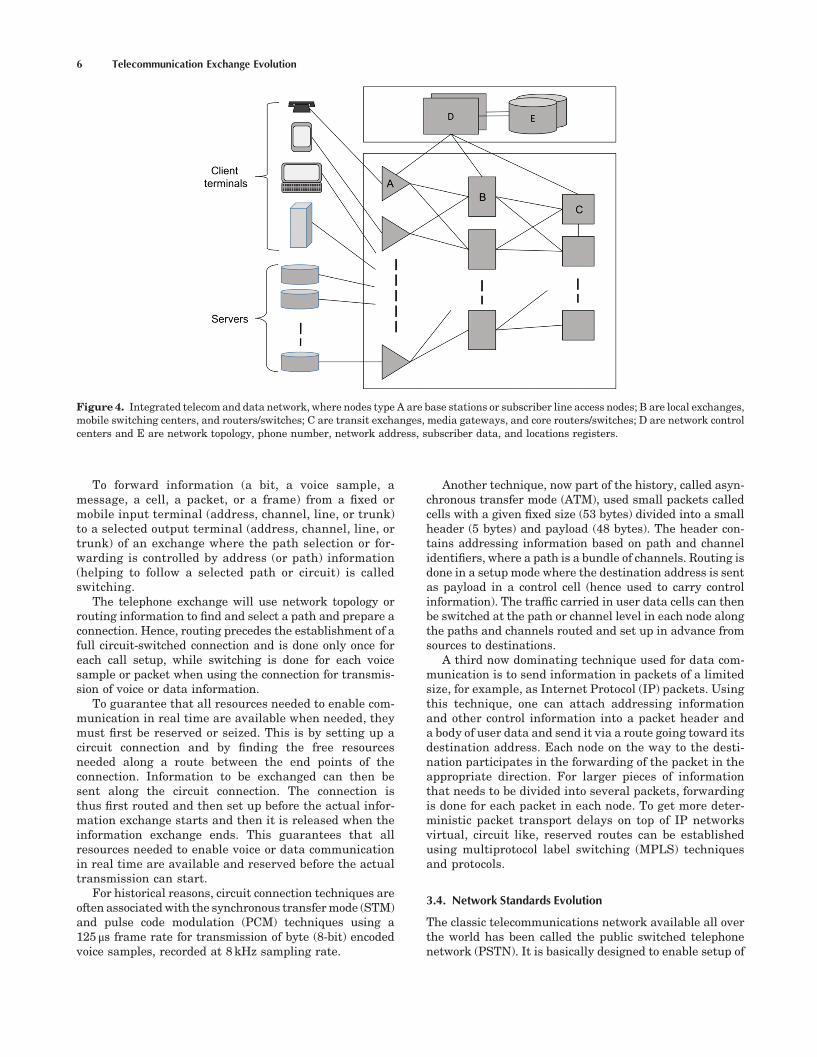
area identify a distribution of subscribers that must beinterconnected in a reasonably efficient way – for exam-ple, in a star or ring-structured physical access network.One can then allocate a number of network nodes ofdifferent basic types that are needed, both to deal withexpected maximum traffic loads and to interconnectthese in a way that keeps transmission costs close to aminimum. The structure of a modern fixed and mobiletelecommunication and data network is illustratedin Figure 4.
We now go back to the external functional networkperspective and especially to how the different functionsare distributed in the physical network. This distribu-tion can be guided by different principles. Simple andcheap functions that are used often and for long periodsof time should be located close to the subscribers. Com-plex and expensive functions used seldom and for shortperiods of time should be placed more centrally in thenetwork and thus be shared by many users. However,with today’s technology and using mainstream compo-nents, complex must not necessarily mean expensiveand hence a complex function if implemented as anintegrated circuit can often be placed close to the sub-scribers, for example, voice coders. Furthermore, theeffects of distribution on reliability, signaling, and main-tenance must also be considered when deciding on func-tion distribution over network nodes.
From the above discussion, one can see that there is noabsolute definition of how networks shall be implementedor what a network node shall contain. Rather, there areseveral possible configurations that can fulfill the require-ments, because not only does the distribution of subscribersas well as their quality of service (QoS) requirements andtraffic patterns differ significantly but also implementationcosts for different types of solutions differ and change overtime.
Going back to and analyzing what an exchange is, onecan see that many of the functions carried out in thedifferent logical networks have traditionally been placedin an exchange node and can still be located in such ageneral node. On the other hand, these functions and hencethe exchange can also be distributed and placed in morespecialized networks and nodes. With well-defined func-tional areas and interfaces between these, it is possible toconfigure networks and network nodes in many differentways. However, for a node or cluster of nodes to be regardedas a telecommunication exchange, it is assumed to havesome basic call access, control, switching, connection han-dling, and charging capabilities.
3.3. Routing and Switching
The task of finding a path (or route) from source to destina-tion is called routing. The task to followapath fromsource todestination guided by end-to-end address information iscalled path selection. Each node that participates in thissimpler forwarding task does not need to know the wholepath butmust be able to analyze thedestination address or apath identity find out to which link or outgoing port theswitching or forwarding should bemade and also find such alink with a trunk that is free to use.
Telecommunication Exchange Evolution 5
W2043PUB2 04/14/2017 11:24:2 Page 6
To forward information (a bit, a voice sample, amessage, a cell, a packet, or a frame) from a fixed ormobile input terminal (address, channel, line, or trunk)to a selected output terminal (address, channel, line, ortrunk) of an exchange where the path selection or for-warding is controlled by address (or path) information(helping to follow a selected path or circuit) is calledswitching.
The telephone exchange will use network topology orrouting information to find and select a path and prepare aconnection. Hence, routing precedes the establishment of afull circuit-switched connection and is done only once foreach call setup, while switching is done for each voicesample or packet when using the connection for transmis-sion of voice or data information.
To guarantee that all resources needed to enable com-munication in real time are available when needed, theymust first be reserved or seized. This is by setting up acircuit connection and by finding the free resourcesneeded along a route between the end points of theconnection. Information to be exchanged can then besent along the circuit connection. The connection isthus first routed and then set up before the actual infor-mation exchange starts and then it is released when theinformation exchange ends. This guarantees that allresources needed to enable voice or data communicationin real time are available and reserved before the actualtransmission can start.
For historical reasons, circuit connection techniques areoften associatedwith the synchronous transfermode (STM)and pulse code modulation (PCM) techniques using a125 μs frame rate for transmission of byte (8-bit) encodedvoice samples, recorded at 8 kHz sampling rate.
Another technique, now part of the history, called asyn-chronous transfer mode (ATM), used small packets calledcells with a given fixed size (53 bytes) divided into a smallheader (5 bytes) and payload (48 bytes). The header con-tains addressing information based on path and channelidentifiers, where a path is a bundle of channels. Routing isdone in a setup mode where the destination address is sentas payload in a control cell (hence used to carry controlinformation). The traffic carried in user data cells can thenbe switched at the path or channel level in each node alongthe paths and channels routed and set up in advance fromsources to destinations.
A third now dominating technique used for data com-munication is to send information in packets of a limitedsize, for example, as Internet Protocol (IP) packets. Usingthis technique, one can attach addressing informationand other control information into a packet header anda body of user data and send it via a route going toward itsdestination address. Each node on the way to the desti-nation participates in the forwarding of the packet in theappropriate direction. For larger pieces of informationthat needs to be divided into several packets, forwardingis done for each packet in each node. To get more deter-ministic packet transport delays on top of IP networksvirtual, circuit like, reserved routes can be establishedusing multiprotocol label switching (MPLS) techniquesand protocols.
3.4. Network Standards Evolution
The classic telecommunications network available all overthe world has been called the public switched telephonenetwork (PSTN). It is basically designed to enable setup of
Figure 4. Integrated telecom and data network, where nodes type A are base stations or subscriber line access nodes; B are local exchanges,mobile switching centers, and routers/switches; C are transit exchanges, media gateways, and core routers/switches; D are network controlcenters and E are network topology, phone number, network address, subscriber data, and locations registers.
6 Telecommunication Exchange Evolution

W2043PUB2 04/14/2017 11:24:3 Page 7
calls and transmission of speech between two or moreusers. However, this network is also used for facsimileand data traffic (sent via modems over the analog partsof the network). Examples of call services are alarm callsand abbreviated dialing, call forwarding, and three-partycalls.
Integrated services digital network (ISDN) was an evo-lution of PSTN that gave the subscribers digital access tointegrated or combined services. ISDN aimed to integratedifferent telecommunication services into the same net-work that transports voice and data in digital form betweennetwork access points. The evolution from analog to digitalend-to-end communication gave safer and more flexibletransfer of information. ISDN provided a range of servicesdivided into bearer services and teleservices. ISDN is basedon the digital telephony network using ordinary two-wiresubscriber lines, 24 or 32 channel PCM link structures, andSignaling System No. 7. Integrated access gives the useraccess to both voice and data services through a singlesubscriber line, whereas combined access allows the use ofseveral subscriber lines. Services include voice, facsimile,and computer connections. ITU-T defines two types of user-network accesses: Basic Rate Access, used for low trafficload, including one 16kbps signaling channel (D) and two64kbps communication channels (B); Primary Rate Access,supporting higher traffic loads, normally including 23 (T1)or 30 (E1) 64kbs communication channels (B) and onesignaling channel (D).
Today ISDN, at least as a service that the end user isaware of, to a large extent is replaced by different Internetand IP protocol-based services with much higher band-width although the ISDN services and protocols still some-times are used to implement links in and access to what wecall the Internet.
The public land mobile network (PLMN) is used as anacronym for all cellular mobile networks with the primaryobjective to provide wireless communication to and frommobile subscribers connected to the fixed network viaradio. The radio interface is implemented by the mobileterminals and the base stations implementing a wirelessaccess network. The base stations are end points in thefixed (wired) network.
Early analog mobile networks based on standards, suchas advanced mobile phone system (AMPS) and the nordicmobile telephony (NMT) are now called the first generation(1G) and their digital versions (DAMPS); global system formobile communication (GSM) and personal digital cellular(PDC) are referred to as second-generation (2G) cellularmobile networks. The third-generation (3G) systems haveincreased the bandwidth and capacity based on code divi-sion multiple access (CDMA) and wideband code divisionmultiple access (WCDMA), such as IMT-2000 and UMTSare designed to support variable speed multimedia commu-nication. Today,wehave the fourth-generation (4G) systemsthat have been developed and deployed step by step follow-ing the ETSI long-term evolution (LTE) roll out plan alsomanaged by the 3GPP (3rd Generation Partnership Proj-ect). 4G uses more advanced coding and modulation sche-mas and has also got some additional frequency spectrumsto use, all resulting in higher bandwidth and capacity.
Important types of network nodes in the PLMN are thefollowing:
• Mobile services switching center (MSC) – controllingthe calls within the PLMN as well as calls to and fromother tele- and data-communication networks.
• Home location register (HLR) – database handlinginformation about which supplementary services asubscriber has activated and in which MSC areathe subscribers phone is currently located.
• Visitor location register (VLR) – database maintaininginformation about the locations of the active phones inthe area controlled by the MSC. The VLR fetchesinformation from the HLR so that the call setup canbe performed without using the HLR each time.
• Media gateway (MGW) – switch, router, and translator(of coded media) facilitating communication betweenRNCs, the core network nodes, and O&M nodes.
• Base station controller (BSC), called radio networkcontroller (RNC) in UMTS, coordinates and controls anumber of radio resources usually located in basestations and some interwork functions such as hand-over between the cells, covered by the base stations.
• Radio base station (RBS) – radio transceiver enablingcommunication with the active MS in the cell.
• Mobile station (MS) – that is, the mobile phone.
Based on the separation of the network in a controlsignaling layer and a user data transport layer, the intelli-gent network (IN) is an architecture aimed at making thetelecom network to work as one integrated system wherenew network services can be developed, introduced, andmade available from a central service control point (SCP).The IN architecture aims at a logical separation of signal-ing, call, connection, and transport. The idea is that localand transit exchanges do the initial number analysis andthen ask the SCP to handle the call, unless it is a simple INservice that can be handled locally. The SCP then executesa service script that results in orders to the exchanges alongthe connection path telling how to proceedwith the call. Forthis communication, the IN application protocol (INAP),that is a part of the signaling system number 7 (SS7)protocol stack, is used. Services are defined by servicescripts or building blocks, including functional componentsdeveloped by the operator using a service design anddevelopment environment.
The telecommunication management network (TMN) isan architecture and standard portfolio aimed to supportoperation andmaintenance. It defines functional areas andprotocols for management in general terms and also morespecific information models for how to monitor and managethese functional areas.
The open systems interconnection (OSI) referencemodelis a standardized layered model of how computer systemscan be interconnected and interoperate that has had andcontinuous to have a strong influence on the way signalingnetworks and their protocols are built. The model definesseven protocol layers: (7) application, (6) presentation, (5)session, (4) transport, (3) network, (2) link, and (1) physical.
Telecommunication Exchange Evolution 7

W2043PUB2 04/14/2017 11:24:3 Page 8
The telecommunication information networking archi-tecture (TINA) is a consortium defining an open architec-ture for telecommunication systems. It focuses on thesoftware architecture. To some extent, this effort can beseen as an attempt to put together some other standard-ization efforts such as OSI, IN, and TMN from a softwarearchitecture point of view.
4. THE FUNCTIONS OF AN EXCHANGE
The telecommunications exchange has evolved into a multi-application digital node that offers its services to con-nected subscribers but also to the operator of theexchange. One example of a service offered to the sub-scribers is telephony calls, and a service offered to theoperator is the ability to charge for services by registeringof charging data in the exchange.
A telecommunications network offers various services tothe subscribers and the network operator. ITU-T hasdivided these services into two main categories:
• Bearer services for transport of speech and data in thenetwork between the user interfaces. The transport ofspeech is to be done in real time with negligibledistortion or alteration of the speech. The bearerservice supports the OSI levels 1–3.
• Teleservices that combines the bearer service withterminal services, such as information processingfunctions. Some teleservices are tied to a specificbearer service, whereas others utilize different bearerservices. Examples of basic teleservices are telephony,facsimile, and computer connection.
The bearer services and the teleservices are dividedinto basic and supplementary services. Telephony is anexample of a basic teleservice, and call waiting is anexample of a supplementary service that gives users addi-tional functionality.
4.1. Basic Telephony
Below is a brief description of the main functions requiredby the exchange in order to set up, maintain, and dis-connect a basic telephone call between two mobile or fixedsubscriber terminals.
Signaling. Early signaling was made in-band, on thesame line where the speech was transmitted. This firstby decadic pulses and later coded as tones of differentfrequencies. A still common in-band signaling system ismultifrequency signaling, where a combination of twotones is sent to a tone-receiver in the exchange. Modernsignaling is based on digital message passing. The globallydominant signaling system for telephony is the SignalingSystem No. 7.
Subscriber Signaling. To request the set up a call, thecalling subscriber alerts the exchange and then sends thedialed number. For an analog access, the alert is made by
the user lifting the handset, when the exchange detects thisit replies by returning a dial tone. The dialed digits are thensent one by one. For a digital (mobile, ISDN, or VOIP)access, the alert and the digits are all sent in one message,this saves bandwidth and decreases the delay for call setup.In both cases the exchange replies with a tone to the callingsubscriber when the status of the called subscriber hasbeen checked.
Number Analysis. The A-number (the calling subscriber)and the B-number (the called subscriber) are analyzed andused as input to routing and charging analysis.
Subscriber Category and Service Analysis. The exchangewill early in the call setup check whether the callingsubscriber has any call service invoked, such as blockingof outgoing calls. The services are sometimes executed inthe local exchange used by the calling or called subscribers,in other cases in a transit exchange or in a separateexchange that handles intelligent network (IN) servicessuch as in a service control point (SCP).
Charging. Charging can be divided into two steps: anal-ysis and output. The analysis is influenced by the chargingmethod (detailed billing, toll ticketing, pulse metering, orflat rate) and the charging rate, depending on a number ofcalls related data set by the operator. The output includesformatting of the charging data along with transfer to areliable storage medium, locally or in a charging andmaintenance center. With exception for advanced services,there has been a trend toward simpler more flat-rate-basedcharging principles.
Routing Analysis. Finding a path from source to desti-nation is called routing and is made mainly by analysis ofthe B-number. Usually, there are two or three (and some-times up to ten) alternative routes to select among. Theselection of a route (trunk group) is guided by priority andload status information. If the first route is alreadyreserved, the next alternative is selected. There aresophisticated routing algorithms that dynamically (bychecking the load) choose a link in order to minimizethe congestion in the network. These dynamic routingalgorithms can be either local or central; the local pro-vides results by using data available in its own exchangesuch as previous success rates on different link choices,while the central algorithms collect input data from otherexchanges in the network.
Connection. Traditionally, this meant the through con-nection of two 64kb/s circuits, one in each direction, estab-lished by the switch. Today, the bandwidths can be muchlarger to support for example real-time video sessions. Aconnection is required to be with limited probability ofblocking, from end to end. This means that the switchfabric must add very low blocking probabilities, in orderto fulfill the end-to-end requirements for calls that passseveral exchanges. The connection also must be well syn-chronized with the exchange and with the rest of the net-work, in order to handle real-time digital speech and videoconnections properly.
8 Telecommunication Exchange Evolution

W2043PUB2 04/14/2017 11:24:3 Page 9
Trunk Signaling. Trunk signaling enables a call to beconnected between subscribers connected to separateexchanges. This by sending signals such as alert messagestelling that a call is to be connected or disconnected alongwith routing information, relevant parts of the dialed digits.Modern signaling systems also support detailed billing,advanced network services, and transparent user data.
4.2. Subscriber Services
A modern computer-controlled exchange that communi-cates via digital messages enable almost any service tobe evolved. However, the service software is not onlylocated in the exchanges but more and more also in termi-nals, service control points, and network databases. Themost cost-efficient location depends on the type of service.For some services where the logic is local (such as abbrevi-ated number, also called speed dialing), it is efficient to dothe translation between abbreviated number and realnumber directly in the calling terminal. For more advancednetwork services such as virtual private networks, free-phones, or universal personal numbers, it is more naturalto locate the service logic in a network node, in eitherordinary exchanges such as the mobile switching centeror fixed local exchange or in other cases in a networkdatabase such as the SCP orHLR. The advantage of centralservice control is that the introduction of new services andfeatures is simplified. In addition, some features requireconsistent data for the entire network, such as the infor-mation in the HLR regarding where a called mobile sub-scriber is located.
More powerful protocols enable more advanced servicesto be implemented in the network. At the same time, thereare an increasing number of services that now are imple-mented in the terminals, and related data is sent trans-parently through the network between the end users. As anexample, ISDN did not took off while transport of datatraffic over the telecom network has increased much morerapidly, where the services are executed in the end-users’computers or smart phones.
Examples of common telephony subscriber services areFreephone, the call is free of charge and instead paid by thecalled party. Conference Call: more than two parties cantake part in a call. Transfer Services: the call is transferredto another telephone immediately or when the called num-ber is busy or not replying. Universal Personal Number:one phone number is used regardless of which mobileterminal or fixed physical connection a person is using.Call Completion Service: when the called party is no longerbusy or nonreplying, the call is reinitiated. Virtual PrivateNetwork: a group of subscribers, for instance a corporation,form a private network with their own charging and tele-phone numbers.
4.3. Cellular Mobile Telephony
Cellular mobile telephony differs from basic telephony,since the subscribers can move freely within the areascovered by the radio access network. As a result, theexchanges in a cellular system must keep track of wherethe subscribers are located and find free radio channels to
use for setup of new calls and during calls when thesubscribers are moving between cells in the covered areas.
The radio frequency spectrum available for mobiletelephony is a scarce resource that is reused by dividingthe space in small areas called cells. The frequency spec-trum is divided into frequency bands, and these bands canin turn be time or code divided into channels. Due to the useof limited power levels, not adjacent cells can reuse fre-quency bands and channels without disturbing each other.
Handover. Handover means to change or switch cellfrom one cell to another with better radio transmissionquality during an ongoing call. The handover decision isbased onmeasurements of received signal quality in up anddown links. Handover can be made several times during acall. This and the fact that handover decisions require thecollection and analysis of measurement data contribute tomaking cellularmobile telephonymore processing resourceconsuming compared to fixed telephony.
Channel Allocation. Channel allocation, aims at findingand assigning free frequency, time and/or code dividedchannels within a cell to calls. The channel allocation logicgives an ongoing call higher priority than a new call.Channel allocation is closely related to the handover func-tion and especially intercell handover, which does hand-over between allocated channels in the same cell.
Location Update. When the mobile phone is turned onand running in idle mode, it listens to control messagesindicating which location area the closest base stationsending control messages belongs to. When a locationarea border is passed, it sends a message to the mobileswitching center (MSC), indicating that the subscriber hasmoved to another location. The information is stored by theMSC, in a visitor location register (VLR), and it is alsostored in the home location register (HLR) if the area ishandled by a new MSC.
Paging. Locating a mobile subscriber within the net-work is called paging. This is done by requesting theHLR in which VLR/MSC and location area where thesubscriber is located, and then sending a paging messageon a control channel called the page channel to all the cellsin that area.
Roaming. When subscribers move to another operator’snetwork than their own, the network can page the sub-scriber and then set up a call to their new location.
4.4. Operation and Maintenance
A modern telecommunications exchange is supported byoperation and maintenance functions that guarantee ahigh quality of service to the operators and the subscribers.Operation is the normal everyday running of the exchange.This includes activities to adapt the exchange to continu-ously changing demands. Examples of operational activi-ties are connection and disconnection of subscribers;change of subscriber data; collection of charging data;and collection of statistics.
Telecommunication Exchange Evolution 9

W2043PUB2 04/14/2017 11:24:3 Page 10
Maintenance includes the prevention, detection, local-ization, and correction of faults. The faults can be detectedautomatically by the exchange or reported to the operatorby the subscribers or other exchanges in the network.Examples of maintenance activities are fault detection,testing, and repair of exchange hardware, for example,trunk lines or subscriber lines; fault detection, auditing,recovery, and correction of exchange software and data;checking of disturbance indicators in various parts of theexchange, such as the power supply system or the controlsystem.
In a modern telecommunications exchange, there areseveral approaches to maintenance. One is preventivemaintenance that involves a set of routine tasks to checkfor faults before they occur; this requires a high level ofeffort to achieve a certain grade of service. Another iscorrective maintenance where faults are dealt with asthey occur; this requires a more selective and limited effortbut may result in a less consistent quality of service. Thebest is to have a proper balance between the preventive andcorrective maintenance.
Statistics are used to supervise traffic load and per-formance in the network and to reconfigure an exchange.This to change or tune its behavior, capacity, or quality ofservice. Particularly for the configuration of locationareas and cells within a mobile network, large amountsof traffic data are used as evidence to support the rightcorrective actions.
All operation and maintenance activities should haveminimal impact on the traffic handling of the exchange.The ideal situation is an exchange where every subscribercan make a call at any time no matter what happens to thesystem. In order to achieve this, the system should berobust to operator errors and allow the performance ofmaintenance and software and hardware upgradeswithoutaffecting the execution of traffic events.
An exchange should be able to be operated and main-tained remotely. The ability to access exchanges remotelyusing an operation and support system (OSS) ensures ahigh level of service to subscribers and low costs for theoperator. A centralized operation also contributes to amorereliable operation of the exchange and a reduction inpersonnel.
5. ARCHITECTURE OF COMPUTER-CONTROLLEDEXCHANGES
The architecture of modern stored program computer-con-trolled exchanges is influenced to a large extent by thecentral control system and its relation to the decentralizedregional control of the switch as well as signaling andtransport trunk resources (Figure 5).
5.1. Modularity
A modular architecture is typically desired to lower thecosts of system handling and make it easier to adapt thesystem to the changing world of telecommunications. In atruly modular system, each module is fully decoupled and
independent of the internal structure of other modules.There are different forms of modularity, for example:
Application modularity: To support the encapsulationand management of several larger applications in onenode.
Functional modularity: The system is defined in termsof functions rather than implementation units. Func-tions are possible to add, delete, and change withoutdisturbing the operation of the system.
Software modularity: The software modules are pro-grammed independently of each other, and interactthrough defined interfaces and protocols. New orchanged modules can be added without changingexisting software.
Hardware modularity: Hardware can be added orchanged without affecting other parts of the exchangeand its operation.
Typically, the implementation of an exchange can bedivided into Application modules, Resource modules, andControl modules.
5.2. Application Modules
On the highest level, the system architecture of theexchange can be divided into various application modulesin analogy to how telecommunications nodes interact andcommunicate, using protocols enabling modules to beadded or changed without affecting other modules.
The application modules implement various tele-communication applications and have standardized inter-faces to resource modules. Application modules thus act asclients to resource modules. In general, an applicationconsists of functions for access and service. Examples ofapplication modules are analog access, digital access,mobile access, PSTN services, ISDN services, MSC
Figure 5. Typical architecture of stored-program-controlledexchange.
10 Telecommunication Exchange Evolution

W2043PUB2 04/14/2017 11:24:4 Page 11
services, and home location register (HLR). This list may beextended with newer functions such as IP-TV distributionservices.
5.3. Resource Modules
To support the applications modules, the resource moduleshandle and coordinate the use of common resources avail-able to applications by means of well-defined interfaces tothe users. Resource modules act as servers giving control ofresources to application modules and may contain bothsoftware and hardware. An important part is the groupswitch. Remote and central subscriber switches (RSS andCSS, respectively) as well as trunks are connected via thegroup switch. The trunks connect the switch to otherswitches, to data networks, to mobile base stations, andso on. The subscriber switch handles the subscriber callsand concentrates the traffic.
The group switch resource module includes functions forselection, connection, and disconnection of concentratedspeech or signal paths. Overall control of the group switchis performed by the central processor system. Regionalprocessors take care of simpler and more routine tasks,such as periodic scanning of the hardware, whereas thecentral control system handles themore complex functions.Associated functions included in the group switchingresource module are network synchronization devicesand devices to create multiparty calls.
The subscriber switch resourcemodule handles selectionand concentration of the subscriber lines; transmission andreception of speech and signaling data to and from thesubscriber equipment (e.g., on-and off-hook detection);mul-tiplexing and concentration of the subscriber lines to savehardware and make more efficient use of the communica-tion links between the subscriber stage and the groupswitch. The subscriber switch should be modular and ena-ble to combine different forms of access in the subscriberstage. The subscriber switch can be colocated with thegroup switch in the exchange (central subscriber switch,CSS) or located at a distance from the exchange (remotesubscriber switch, RSS).
The remote subscriber multiplexer (RSM) is an add-onsubscriber access node, used in the access network, to servesmall groups of subscribers. It provides both mobile andstandard telephony connections. The RSMmultiplexes andconcentrates the traffic to the subscriber switch but doesnot carry out traffic switching functions.
The trunk and signaling resource module includes cir-cuits for connecting trunks and signaling devices to thegroup switch. It also handles the adaptation to differentsignaling systems, namely, common channel signaling aswell as various register and line signaling systems.
The traffic control resource module contains the traffichandling and the traffic control functions of the exchange.This module is responsible for finding the most suitableroute between calling and called subscribers and of verify-ing that call establishment is allowed.
The operation and maintenance resource module ena-bles tasks such as supervision of traffic, testing of thetransmission accessibility and quality, and diagnosticsand fault localization of devices or trunks.
The common channel signaling resource moduleincludes the signaling terminals and the message transferpart (MTP) functions for common channel signaling sys-tems such as SS7.
The charging resource module is used in exchanges thatact as charging points. Pulse metering and specified billing(toll ticketing) are often offered. It is often possible tocharge both calls and services based on usage of subscriberservices and supplementary services as well as activation/deactivation of subscriber services and supplementaryservices.
5.4. Control Modules
Control modules provide operating system functions,input–output functions, basic call service functions, andso on. The primary function of a controlmodule is to providethe real-time processing and execution environmentrequired to execute software in application modules andresource modules used to perform traffic-handling func-tions and call services. The processing can be centralizedwhere one processor takes care of all tasks, or distributedwhere the processing of information is distributed overseveral processors.
Execution of telecom software imposes stringent real-time requirements on the control system. Call attemptsarrive stochastically, short response times are needed, andoverload situations must be handled. The main controlmodules are the central processor(s); the data store to storecall data; and the program store to store the actualprograms.
In order to achieve an efficient overall control system, itcan be divided into the following:
Central control: One or more processors that performcomplex program control and data-handling taskssuch as execution of subscriber services, collectionof statistics and charging data, and updating ofexchange data and the exchange configuration.
Regional control: Distributed processors that performroutine, simple, frequent, and repetitive tasks, forexample, input/output processing and protocol han-dling. They are of different types optimized for theirmain tasks and often have strict real-time andthroughput requirements.
5.5. Switching Techniques
Until about 1970, most switches were analog and based onelectromechanical rotor switches and crossbar switches.Since then the digital techniques have become dominant.Digital switches have been based on synchronous time andspace multiplexed circuit switch technology. For data com-munication, packet switching technology is mostly used. Inorder to allow voice and data to share a common infra-structure, asynchronous transfer mode (ATM) was devel-oped but has now largely been replaced by IP technology.Synchronous circuit, packet and ATM cell, and IP packettraffic are often carried by synchronous transfer mode(STM) carrier and synchronization technology over longer
Telecommunication Exchange Evolution 11

W2043PUB2 04/14/2017 11:24:4 Page 12
distances often complemented by Ethernet technology inthe local access areas.
A space selector selects one out of several incoming lines(Figure 6a). A space switch connects physical lines in thespace domain (see Figure 6b) and a time switch changes theordering sequence of data (voice) samples in the timedomain, illustrated in Figure 6c. A space to time selectortime-multiplexes several incoming lines on one line(Figure 6d).
An STM-based switch architecture is made up of acombination of time and space switches (T and S, respec-tively). The switch elements T and S can be combined inseveral ways to realize a high capacity switch and make itconfigurable in many ways. Usually, time switching is usedin input and output stages and space switching is oftenused in central parts of a switch. This basic time–space–time (TST) switch structure can be used both in subscriberand in group switching stages. The first part of a TSTswitch is a time switch, which interchanges time slotsbetween the external incoming digital paths and the spaceswitch. The space switch connects the time switches at theinput and the output. The last part of the TST switch istypically another time switch, which connects the time slotsbetween the external outgoing digital paths and the spaceswitch (Figure 7).
The time switch moves data contained in each time slotfrom an incoming bit stream to an outgoing bit stream butwith a different time slot sequence. To accomplish this, thetime slot data is temporary stored in a data store (DS)memory and then placed in a new time slot position. These
operations need to be controlled by information stored in acontrol store (CS) memory. The timing of DS and CS iscontrolled by a time control (TC). Examples of controlactions are time slot busy or time slot idle.
A typical space switch consists of a cross-point matrixthat realizes the switching of time slots in space. Thematrix can be divided into a number of inputs and anumber of outputs and is synchronized with the timeswitching stages via a common clock and a control store.
Switch architectures based on asynchronous transfermode (ATM) was designed to handle small packets, calledcells, with a fixed size (53 bytes) divided into header(5 bytes) and payload (48 bytes). The header containsvirtual path identifiers (VPIs) and virtual channel identifi-ers (VCIs), where a virtual path (VP) is a bundle of virtualchannels (VC). Traffic can be switched at the VP or VC levelcell by cell. Associated with a VP or a VC is a quality ofservice (QoS) contract. In order to guarantee the switchingof cells according to the contract without unacceptable cellloss, a number of queues are used at the input ports andoutput ports of the switch. Between input and output ports(including buffer queues and cell multiplexers and demul-tiplexers), a space matrix often is used, as in Figure 8.
Other switching techniques used in a tele-communication exchange include Ethernet and Rapid IOswitches as well as IP packet routers, each with their owncharacteristics. Embedded IP routers, for IP forwarding,are useful for nodes that connect different IP networks.Sometimes, several switches are used inside a node.
Figure 6. Examples of selection in space (a), switching in space (b), switching in time (c), and selection from space to time (d).
Figure 7. Typical STM switch with TST structure.Figure 8. Typical ATM or packet router/switch structure withinput and output buffering ports and control space switch.
12 Telecommunication Exchange Evolution

W2043PUB2 04/14/2017 11:24:4 Page 13
6. QUALITY OF SERVICE REQUIREMENTS
6.1. Availability
High availability of the telecom network and associatedservices is important. The requirements on maximumunavailability are in the order of one or a few minutes ofsubscriber unavailability per year. This includes downtimedue to faults in the exchange or in the transmission equip-ment, but also unavailability due to faults in the softwareor due to planned software upgrades and often also acci-dents outside the control of the vendor, such as fires,damaged transmission cables, and incorrect operation ofthe exchange. Several methods are used to increase theavailability of the exchange to the subscriber: redundancy,including fault-tolerant processors; segmentation; diagnos-tics of hardware and software faults; recovery after failure;handling of overload; disturbance-free upgrades and cor-rections; robustness to operator errors.
In order to cope with hardware faults redundancy, forexample, redundant hardware is used for those parts of theswitch that are critical for traffic execution. Requirementsare in the order of 1000 years for the mean time betweensystem failures (MTBSF). Often a redundant processor isavailable in synchronized execution (hot standby), readyfor a transparent takeover if a single hardware fault occursin one processor. An intelligent fault analysis algorithm isoften used to decide which processor is faulty. In a multi-processor system, n+1 redundancy is normally used,where each processor can be made of single, double, ortriple hardware. When one processor fails, its tasks aremoved to the idle (cool standby) processor. A similar redun-dancy method is based on load sharing, where the tasks ofthe failed processor are taken over by several of the otherprocessors that are not overloaded themselves.
The group switch hardware is also normally duplicatedor triplicated, because it is so vital to the exchange func-tions. The less central hardware devices, such as trunkdevices, voice machines, transceivers, signal terminals,and code receivers, are normally pooled, so that a faultydevice is blocked from use and all users can instead accessthe remaining devices until the faulty device is repaired.
To avoid system failure, a fault must be kept isolatedwithin a small area of the exchange. This is done bysegmentation of the hardware, with error supervision atthe interfaces. In software, the segmentation is made bypartitioning of and restricted access to data structures;only owners of data can change the data, where the ownercan be a call process or a function.
After the occurrence of a fault in hardware or software,the fault must be identified, localized, and diagnosed, itseffect restricted, and the exchange continue in its normalstate of execution. For this to work, the fault diagnosticsmust be extensive and automatic. The exchange must beable to identify the faulty software and hardware and mustbe able to issue an alarm, usually to a remotely locatedoperator.
After that a fault has been detected, the effect should berestricted to only the individual call or process (forinstance, an operator procedure or a location update by amobile subscriber) or an individual hardware device. This
faulty call or process be aborted, while the rest of theexchange is not affected. This recovery process must beautomatic and secure. In a small fraction of events, thefault may remain after the low-level recovery, or the initialfault is considered too severe by the fault handling soft-ware, so that a more powerful recovery procedure must beused. The process abort can be escalated to temporaryblocking of hardware devices or software applicationsand, if required, result in the restart of an entire processoror a number of processors. If the restart fails in recoveringthe exchange into normal traffic handling, new data andsoftware are loaded from internal or external memory andthe exchange is then restarted.
An exchange is required to execute traffic literally non-stop and when overloaded by more traffic than it canhandle, the overload handling including rejection of over-flow traffic must be made gracefully. ITU requires, that anexchange that is offered 150% of what it was designed forshould still have 90% of its maximum traffic handlingcapacity. The exchange must also be able to function with-out failure during extreme traffic loads. Such extreme loadscan be both short peaks lasting a few milliseconds orsustained overload due to failures in other parts of thenetwork. Overload handling is made by rejecting excesstraffic very early in the call setup, before it has used toomuch processor time or scarce resources in the switchingpath. Figure 9 shows the overload performance with andwithout an overload control function.
Disturbance free upgrading of software packages andreplacement or extension of hardware to the exchangeshould be supported ensure that ongoing traffic executionis not harmed. This both for fault corrections andwhen newfunctions are introduced. The architecture must thus allowtraffic to be executed in redundant parts, while some partsof the exchange are upgraded.
Security against unauthorized access is implemented byuse of passwords and physically locked exchange premises.To support robustness in case of operator errors, the userinterface part of the exchange supervise that valid opera-tion instructions are followed for operation and mainte-nance, or else issue an alert or prohibit other procedures.Logging of operator procedures and functions for undoing aprocedure can be used. If a circuit board or other hardwarepart is incorrectly removed from the exchange, the
Figure 9. Call capacity as function of traffic load (number of callattempts) with and without overload control.
Telecommunication Exchange Evolution 13
W2043PUB2 04/14/2017 11:24:4 Page 14
exchange should restrict the fault to that particular part,use redundant hardware to minimize the effect of the fault,and indicate that this part is unavailable.
The real-time delays in the exchange must be restrictedto transmit speech correctly, to ensure grade of servicerequirements. Highly loaded packet-switched connectionsmay have problems achieving good real-time speech qual-ity for this reason. Circuit-switched networks have betterreal-time performance regarding delays and grade of ser-vice for voice and video, compared with packet data net-works. ATM switching, due to its short and fixed size cell/packets, also fulfills the requirements. However, due tohigher and higher bandwidths and capacity but also due tothe use of label switching (virtual circuit) techniques,packet switching now usually give good quality of serviceand this even for real-time video.
6.2. Scalability
There is a need for scalable exchanges regarding capacity,from very small (such as local exchanges in desolate areas)to very large exchanges needed in dense metropolitanareas, transit exchanges, and MSCs. Furthermore, thereis sometimes also a need for downward scalability regard-ing physical size and power consumption, particularly forindoor or inner city mobile telephony.
The upward scalability is limited by dynamic real-timecall setup capacity; static call traffic handling capacity;grade of service (delays); memory limits; data transfercapacity; and dependability risks.
The downward scalability is limited by the cost tomanufacture, operate, and handle; limited gain due tosharing of resources; physical size is limited by require-ments for robustness; and energy consumption limited bythe hardware technology available.
Processing Capacity. Advanced services and techniquesrequiremore processing capacity. This trend has been validfor the replacement of analog technology with digitalprocessor-controlled functions and also the developmentof signaling systems from decadic via multifrequency topacket mode digital signaling, including trunk signalingprotocols such as ISDN user part (ISUP) together withmobile application part (MAP) and transaction capabilityapplication part (TCAP) and the handling of mobility. Inthe charging area, going from pulse metering, via detailedbilling and now toward flat rate also affects the call capac-ity. The number of calls per subscriber has increased due tolower call costs from deregulation and due to the use ofsubscriber redirection and answering services. Users hasalso changed their behavior due being more available viatheir mobile phones usually resulting in more but shortercalls.
Traffic Capacity. It is very important ensure sufficientlylow congestion in the exchange and in the network. Nor-mally, the switch fabric is virtually nonblocking, and thecongestion occurs in other resources, such as access lines,trunk lines, and other equipment. The relation betweencongestion probability and the amount of traffic is wellknown, if all devices are accessible and the traffic follows a
Poisson process; that is, the times between offered calls areindependent and exponentially distributed. In these cases,the probability can be calculated. In more complex trafficscenarios with non-Poisson traffic, the congestion proba-bilities are analyzed by help of simulation techniques.
Memory. The amount of memory used per subscriberline or trunk line is a way to measure the complexity of atelecom application. The trend in this area is similar to thatof processing capacity, and the same factors are responsiblefor the increase in memory needs. Due to the real-timerequirements, fast primary memory is used extensively,and secondary memory is only used for storage of backups,log files, and other data where time is not critical.
Transfer Capacity. A third part of the switching system’scapacity is the data transfer from the exchange to othernodes, for example, to other exchanges and network data-bases, billing centers, statistical post processing, and nodesfor centralized operation. Therehas beenagrowingdemandfor signaling link capacity due to large STPs, for transfercapacity from the exchange to a billing center due todetailed billing and large amounts of real-time statistics,and to transfer capacity into the exchange due to theincreased amount of memory to reload at exchange failure.
Dependability Risks. Although dependability has incre-ased for digital exchanges, there is a limit as to how largethe nodes in the network that can be built. The morehardware and the more software functions assembled inone exchange, the more errors there are. The vast majorityof these faults will be handled by low-level recovery, trans-parent to the telecom function, or only affecting one pro-cess. However, a small fraction of the faults can result in amajor outage that affects the entire exchange during sometime. The risk of a 1-h complete exchange failure during ayear for one exchange must be low. If we add the function-ality of an exchange node we increase the amount of soft-ware and presumably the number of faults in the node; therisk of a major outage should be larger; and especially in anew exchange introducing new software, potentially withnew faults. Unavailability due to completely stopped trafficexecution must be much less than the total effect of soft-ware process abortions and devices blocked due to hard-ware errors. Another argument for limiting the size andcomplexity of the nodes from a dependability point of viewis that network redundancy is then required but can only beused if there are several exchanges in the network.
6.3. Life-Cycle Cost
Since the 1980s, life-cycle-related costs such as the operat-ing cost has become larger than the investment cost of anexchange. Life-cycle costs are also due to product handlingmatters, such as ordering, installation, and spare partsupply. The emphasis on more efficient operation andmaintenance has increased, regarding both ease of useand utilization of centers that remotely operate and main-tain a number of exchanges that are not staffed.
For central operation, more robust methods for remoteactivities have evolved. Software upgrades and corrections,
14 Telecommunication Exchange Evolution

W2043PUB2 04/14/2017 11:24:4 Page 15
alarm supervision and handling, collection of statistics andcharging data, and handling and definition of subscriberdata are all made remotely. Transmission uses a multitudeof techniques and protocols. Open standard protocols havetaken over from proprietary protocols. For ease of use, thetelecommunication management network (TMN) was anattempt by ITU to standardize the operator interface. Afterseveral years, this standard is still not used much. Instead,the operator interface is to a large extent dependent on theexchange manufacturer as well as the requirements fromthe telecom operator company. The coexistence of severalopen and proprietary user interfaces is common.
7. EVOLUTION TRENDS
7.1. Technology Trends
Semiconductor process improvements, higher chip fabrica-tion yields, and increasing numbers of connectivity layers –result in that the storage capability of memories andthe execution speed of processors have doubled every18 months during almost 50 years, following the so calledMoore’s law. This exponential growth of transistors perchip has now slowed down somewhat due to voltage limits,current leaks, clock frequency, and power density limits;and enforce new more parallel hardware architectures inorder to keep energy use within reasonable limits.
The development of optical fibers, including the intro-duction of wavelength multiplexing, has also evolved veryfast. There are still many factors that lead to cheaper nodesand higher bit rates in the network. At the same time,digital coding and compression techniques have beenimproved in an almost equally impressing rate that makesit possible to transmit voice with traditional telecom qual-ity using only a fraction of the bandwidth that was usedyesterday. Video services making use of much larger band-widths have also become common. These developments arechanging the design of both nodes and networks.
It is also important to provide increased interoperabilitybetween network standards, since the end users do notwant to be concerned about where a person is physicallylocated or to which network the person is connected. Theintroduction of universal personal numbers solves this andhas lead to a convergence of fixed and mobile telephony.The possibility of accessing short message services (SMS),fax, and e-mail via both fixed and mobile devices and voiceover IP (VOIP) and Video on Demand are examples ofservices that illustrate the needs for interoperability andconvergence of the tele- and data-communication networks.A problem today seems to be that most proprietary IP-based voice and messaging services requires their users tocreate new personal user IDs in a way controlled by theservice providers. You may at best be able to use your(Google, Apple, Facebook, etc.) ID for more than one serviceand sometimes also in other systems.
High bit rates at a low price, combined with the demandfor real-time multimedia services, indicate that the net-work must either become more flexible or consist of severaldifferent but interoperating networks. Packet and new,more flexible circuit switching techniques supported by
new protocols (such as MPLS) can solve these needs. Inorder to integrate service execution, control and connectiv-ity horizontally across multiple access networks, a layeredarchitecture approach can be used using a common trans-port layer based on IP and Ethernet technology over fiberrather than delivering single services such as voice teleph-ony or data access (vertically integrated networks). Thisarchitecture supports efficient IP packet-based transport ofboth signaling and payload. By using a common mostly IP-based infrastructure one can handle all network servicesfor communication between fixed and mobile terminals.
7.2. Network Convergence and Evolution
Calls and other similar media sessions can now be setup inmany ways and the protocols and messages used havechanged over the years. The ISDN call setup protocolmentioned previously has been complemented with proto-col collections such as H.323 that enable call setup includ-ing coded and compressed voice calls and the choice of whatcoding standard to use for a specific call session. TheSession Initiation Protocol (SIP) has a similar but morelimited scope for the setup of communication sessionsbetween two parties and selection of coding standard usingthe Session Description Protocol (SDP).
The IP Multimedia Subsystem (IMS) architecturedefined by the European Telecommunications StandardsInstitute (ETSI) and by the 3rd-Generation PartnershipProject (3GPP) allow video and other media forms to beexchanged and charged on a session-by-session basis frompeer to peer in a way similar to classic phone calls. The IMSarchitecture uses a call session control function (CSCF)(important part of an IMS application module) as handlerof SIP-initiated sessions.
The Internet and the possibility to encapsulate andtransport digitized and encoded voice packets over IP net-works, refereed to as Voice over IP (VOIP), has changed theworld of telecommunication a lot. Skype is one example of apopular service that allows voice calls to be setup betweencomputers and other (computer containing) terminals suchas smart phones. It also allows calls from a computer to anyordinary phone via a call server and media gateway con-nected to the phone network.
When computers are used as terminals for real-timecommunication a problem is that most users do not havetheir computers on all the time. A consequence is that youhave to agree on some call setup conventions, like “you canmostly reach me between 18:00 and 20:00” or you need toannounce your intention to setup a call by some othermeans like by sending an SMS. The problem has nowmore or less disappeared when most people use smartphones that are kept on most of the time. This meansthat people are reachable where and when they want.
The convergence and evolution toward a common infra-structure is sometimes called the NewGenerationNetwork(NGN) architecture (Figure 9), but also can be associatedwith several other concepts discussed below (Figure 10).
This network evolution extending beyond but perhapsinspired by IN is supported by techniques for separationof control and switching such as the protocol H.248 aimedto allow a so called soft switch to control one or more
Telecommunication Exchange Evolution 15

W2043PUB2 04/14/2017 11:24:5 Page 16
media gateways and/or switch nodes. Software-definedexchanges, soft-switches, or media gateway controllersinclude a call session control function (CSCF) for handlingof voice calls and other session-oriented services. They arealso responsible for that sessions can be connected via aphysical switch and media gateway (MGW) and handlethe signaling between network nodes and other networks.The CSCF establishes a call session, and further managesreserved connection path resources, end to end. This forexample through a backbone network based on an ATM,IP, or Ethernet and processors for media stream process-ing. The MGW nodes provides physical switching, codingtranslations, and interfaces to access nodes and othernetworks.
The software-defined network (SDN) is a similar virtu-alization approach that has evolved from the IP networkingcommunity. SDNproposes a logical or virtual network builtas a layer above the physical concrete networking layers. Itis intended to support a separation between control anddata switching layers similar to ambitions such as SS7, IN,and NGN. More specifically using the OSI stack terminol-ogy a SDN is operating above and thus decouples fromlower network layers such as the IP layer. The idea is toallow different services and users to share underlyinghardware resources in a flexible and secure way. As inmany other networking techniques this requires that newprotocols are introduced to create, encapsulate, differenti-ate, and manage the networks, services, and users fromeach other. The protocols needed to establish and run SDNcan essentially be separated in service setup protocols andtransport protocols.
The behavior of a SDN is supposed to be setup using theOpenFlow protocol. OpenFlow allows a table driven andthus software-defined network behavior where not only theforwarding but also simple alteration actions of packetheaders can be setup by a central network controller actingfrom above. Setting up what in essence is a virtual circuitconnection speeding up the packet carried data flow.
Network function virtualization (NFV) is anotherarchitecture that is strongly related to SDN. NFV aimsat making functions or services implemented as virtualnetwork functions (VNF) that controls and gives servicesto the network to be as platform technology and locationindependent as possible. To achieve this, the VNF areintended to execute on one or more virtual machines incomputing clusters or clouds, based on standardizedmemory and processing resources, made accessible viathe network.
3GPP has been strongly influential on the develop-ment of 3G via the long-term evolution (LTE) plan toward4G and now more recently towards 5G, by ITU referred toas IMT2020. These last developments of the wirelesstechnologies not only aim at much higher bandwidthsbut are for example also aimed to support very low energyconnections to the so called Internet of Things (IoT) aswell as device and device-to-device communications, thussupporting machine to machine (M2M) and vehicle tovehicle or vehicle to infrastructure (V2X) and connectedcars and cooperative intelligent transport system (C-ITS)needs.
BIBLIOGRAPHY
1. R. L. Freeman. Telecommunication System Engineering, 4thed.; Wiley, 2004.
2. D. Minoli. Telecommunications Technology Handbook. ArtechHouse, 1991.
3. M. Schwartz. Telecommunication Networks: Protocols, Model-ling and Analysis. Addison-Wesley, 1987.
Figure 10. Converged network architecture with virtualized decoupling of access, transport, control, and service functions.
TONY LARSSON
Halmstad University, Halmstad, Sweden
16 Telecommunication Exchange Evolution