potential hazards of a petrochemical plant if subjected to ... · figure 2-1 crude oil refining...
TRANSCRIPT
i
Department of Environment, Land and Infrastructure
Engineering
Potential Hazards of a petrochemical plant if subjected to
seismic activity
by
TU QI
Supervisor: SURACE CECILIA
Co-supervisor: VASQUEZ MUNOZ LUZ ELIZABETH
December 2018
ii
Content
Abstract .................................................................................................................. 1
1. Introduction ............................................................................................................. 2
2. Chemical Processing in a Petrochemical Plant ....................................................... 4
2.1 Separation ........................................................................................................ 4
2.1.1 Dewatering & Desalting ....................................................................... 4
2.1.2 Preflash Drum ....................................................................................... 5
2.1.3 Distillation............................................................................................. 6
2.2 Conversion ....................................................................................................... 7
2.2.1 Catalytic Cracker .................................................................................. 8
2.2.2 Hydrocracking....................................................................................... 8
2.2.3 Alkylation .............................................................................................. 8
2.2.4 Catalytic Reformer ................................................................................ 8
2.2.5 Coking Operations ................................................................................ 9
2.3 Treatment ......................................................................................................... 9
2.3.1 Hydro Desulfurization ........................................................................ 10
2.3.2 Chemical Storage ................................................................................ 10
2.4 Blending. ........................................................................................................ 10
2.4.1 Blending Unit ...................................................................................... 11
2.4.2 Finished Products and Their Uses ....................................................... 11
3. Physical Units involved in the Chemical Processing ............................................ 12
3.1 2D Satellite Map of Onsite Facilities in Tupras Izmit Refinery .................... 12
3.1.1 Crude Storage Tanks ........................................................................... 13
3.1.2 Processing Area ................................................................................... 15
3.1.3 Semi-refined and Refined Storage ...................................................... 16
3.1.4 Gas Storage Tank (spherical Storage Tanks) ...................................... 16
3.2 2D Satellite Map of Offsite Facilities in Tupras Izmit Refinery .................... 17
3.2.1 Waste Water Treatment Plant .............................................................. 17

iii
3.2.2 Energy Generation Unit (Electric power distribution) ........................ 18
3.2.3 Flare Stack .......................................................................................... 18
3.2.4 Distribution/Transportation ................................................................. 19
3.2.5 Plant Administration ........................................................................... 20
4. Kocaeli Earthquake in 1999 in Turkey ................................................................. 21
4.1 Earthquake Magnitude ................................................................................... 22
4.2 Tupras Izmit Refinery subjected to Kocaeli Earthquake ............................. 22
4.2.1 Fires Caused by Earthquake................................................................ 23
4.2.2 Observed Damage ............................................................................... 24
5. Risk Factors of a Petrochemical Plant subjected to Seismic Load ....................... 28
5.1 Structures Design ........................................................................................... 28
5.1.1 Storage Tank ....................................................................................... 29
5.1.2 Other Structures .................................................................................. 31
5.1.3 Equipment ........................................................................................... 32
5.2 Real-time Monitoring..................................................................................... 34
5.2.1 Real-time Prediction ........................................................................... 34
5.2.2 Real-time Prevention .......................................................................... 36
5.3 Post-earthquake Environment .................................................................... 36
5.3.1 Post-earthquake Buildings State Evaluation ....................................... 37
5.3.2 Environment Pollution ........................................................................ 37
5.3.3 Social and Economic Impact .............................................................. 40
6. Conclusion ............................................................................................................ 41
7. Reference .............................................................................................................. 42
iv
List of Figure
Figure 2-1 Crude oil refining process (https://www.burckhardtcompression.com)4
Figure 2-2, separation processing components (www.magnetrol.com).................. 5
Figure 2-3, conversion operation components (www.magnetrol.com) .................. 7
Figure 2-4, Treating operational system (www.magnetrol.com) ............................ 9
Figure 2-5, Blending component (www.magnetrol.com) ..................................... 10
Figure 3-1, Main components of a refinery. ........................................................ 12
Figure 3-2, 2D satellite map view of the refinery ................................................ 13
Figure 3-3, 2D satellite map view of storage tanks ............................................. 14
Figure 3-4, Floating roof & Fixed roof tank model (Antonio Di Carluccio, 2007)
...................................................................................................................... 14
Figure 3-5, 2D satellite map view of processing area .......................................... 15
Figure 3-6, 2D satellite map view of finished products tanks ............................. 16
Figure 3-7, 2D satellite map view of Gas tanks ................................................... 17
Figure 3-8, 2D satellite map view of waste water treatment ............................... 18
Figure 3-9, 2D satellite map view of Electric power distribution........................ 18
Figure 3-10, 2D satellite map view of flare stack ................................................ 19
Figure 3-11, 2D satellite map view of transportation .......................................... 20
Figure 3-12,2D satellite map view of refinery headquarter ................................. 20
Figure 4-1, Map of affected region showing locations and size of horizontal offsets
and a vertical offset (https://www.preventionweb.net/publications/view/2589.)
...................................................................................................................... 21
Figure 4-2, the typical effects of earthquakes of various magnitudes near the
epicenter (USGS) ......................................................................................... 22
Figure 4-3, Plan view of Izmit refinery in 1999 and location of damage
facilities.(Kohei Suzuki, 2000) .................................................................... 23
Figure 4-4, The damage of Wharf site ................................................................. 25
Figure 4-5, The damage of Tank (Halil S and Andrew S.W,2004) ...................... 26

v
Figure 4-6, Tanks destroyed by Fire (Halil S and Andrew S.W,2004) ................ 26
Figure 4-7, The damage of Heater unit (Heater stack). (Halil S and Andrew
S.W,2004) ..................................................................................................... 26
Figure 4-8, The damage of Pipeworks (Halil S and Andrew S.W,2004) ............. 26
Figure 4-9, The damage of steel Column (Mohsen R. & Guy M., 2000) ............ 27
Figure 5-1, Retrofitting on the naphtha tank TK-202 burned during the fire.(Girgin
2011) ............................................................................................................ 31
Figure 5-2,The damage of pipeworks by stack collapse (Mohsen R. & Guy M.,
2000) ............................................................................................................ 33
Figure 5-3, The damage of joints (Paolacci, 2012) .............................................. 33
Figure 5-4, Seismic accelerogram (Sezen and Whittaker 2006) .......................... 35
Figure 5-5, Yearly distribution of crude-oil processed by Tupras refinery (Girgin
2011) ............................................................................................................ 39

vi
List of Table
Table 4-1, Observed damage ................................................................................ 25
Table 5-1, Selected safety and fire-fighting system improvements at the refinery
(S. Girgin, 2011) .......................................................................................... 38

1
Abstract
The impact of natural hazards which triggers technological accidents at
industrial facilities is called Natech event. Natechs have been recognized as an
emerging risk for industrial facilities. Adequate preparedness, proper emergency
planning, and effective response are crucial for the prevention of natechs and
mitigation of the consequences. Even the largest and seemingly well-prepared
facilities can be vulnerable to natechs if potential risks are not considered
adequately. Risk factors, identified for a seismic activity which strikes an industrial
plant, play a significant role in the seismic performance of social systems and in
the emergency response after earthquake. Risk factors detection provides
fundamental basis for disaster prevention systems design. Earthquake nature,
limited resources, few mitigation measures, and lack of efficient communication
aggravate the risk factors. Therefore, through analysis of previous occurred
earthquakes, we can summarize and enumerate possible risk factors in a seismic
activity. The 17 August 1999, Kocaeli earthquake, which was a devastating disaster
hitting one of the most industrialized regions of Turkey, offers opportunities in this
respect (Girgin, 2011).

2
1. Introduction
Several accidents in the industrial field in recent decades have proved that natural
disasters can cause serious damage to equipment, leading to loss of containment,
resulting in significant direct and secondary hazards. In the case of a seismic, the
earthquake can cause simultaneous damage to different equipments, and the effect can
be amplified due to the safety system failure and the domino effect. For example,
Kocaeli earthquake, 1999, in Turkey; Wenchuan earthquake, 2008, in China; Tohoku
earthquake and the subsequent tsunami, 2011, in Japan. Seismic loading can cause
serious accidents to industrial plants as shown in past several occasions. Although the
potential risks of refineries are extensive and uncalculated, it is possible to find out
earthquake risk factors values through research, in order to continuously optimize the
structure of the refinery and improve the ability of the refinery's overall system to
resist earthquakes. Based on analysis of structural direct damage suffered by refinery
during an earthquake and on secondary hazards to surrounding environment, this
thesis summarizes the potential risk factors of the refinery for seismic events and
provides a powerful help for future research and development.
Kocaeli Earthquake in 1999 to Tupras Izmit Refiney is a great representative
example for this study. The devastating Kocaeli earthquake hit one of the most
industrialized regions of Turkey, resulting in more than twenty-four industrial plants
damaged. In particular, the damages to Tupras refinery were very severe; area of the
plant, of tanks farm, and of landing place was totally damaged. An example of domino
effect caused by a structural collapse was the breakdown of a concrete chimney that
caused a big release of dangerous substances and damages to surrounding equipment
(Paolacci, Giannini et al. 2012)
Industrial plants are complex systems, and because of the numerous connections,
equipment and components, and operational complexity, they are particularly
susceptible to earthquakes (local vulnerabilities). The chapters 2 and 3 introduce the
complex characteristics of chemical plants regard the aspects of process flow and of
3
physical units which are basic components of the refinery. The chemical processing
and its corresponding facilities and equipments in the petrochemical plant are basic
understanding for risk factors. The processing is mainly divided into four categories:
separation, conversion, treatment, and blending. In these four main operational steps,
they are further subdivided into other specific chemical units due to different division
of labor by understanding the chemical processing, it is possible to figure out the
physical units related to production procedures.
After understanding the refinery structure, the risk factors of the refinery system
subjected to the earthquake are explained by analyzing the specific situation of the
Izmit refinery, reviewing the collected studies the past few years. In general the risk
factors for large chemical plant subjected to seismic activities include (a) structure
design; (b) real-time monitoring; and (c) post-earthquake community behavior; The
fifth Chapter of the paper provides a more detailed analysis of those risk factors. The
presented lessons, learned from case study of Tupras Izmit Refinery, can be useful as
well for other industrial plants located in high seismic risk areas.
4
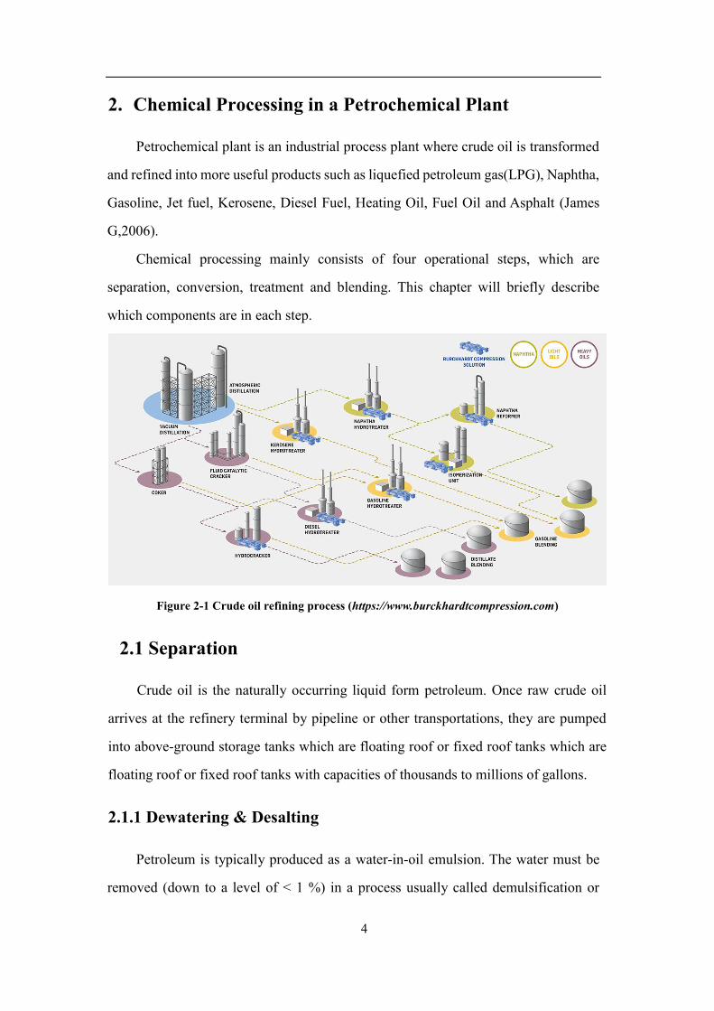
2. Chemical Processing in a Petrochemical Plant
Petrochemical plant is an industrial process plant where crude oil is transformed
and refined into more useful products such as liquefied petroleum gas(LPG), Naphtha,
Gasoline, Jet fuel, Kerosene, Diesel Fuel, Heating Oil, Fuel Oil and Asphalt (James
G,2006).
Chemical processing mainly consists of four operational steps, which are
separation, conversion, treatment and blending. This chapter will briefly describe
which components are in each step.
Figure 2-1 Crude oil refining process (https://www.burckhardtcompression.com)
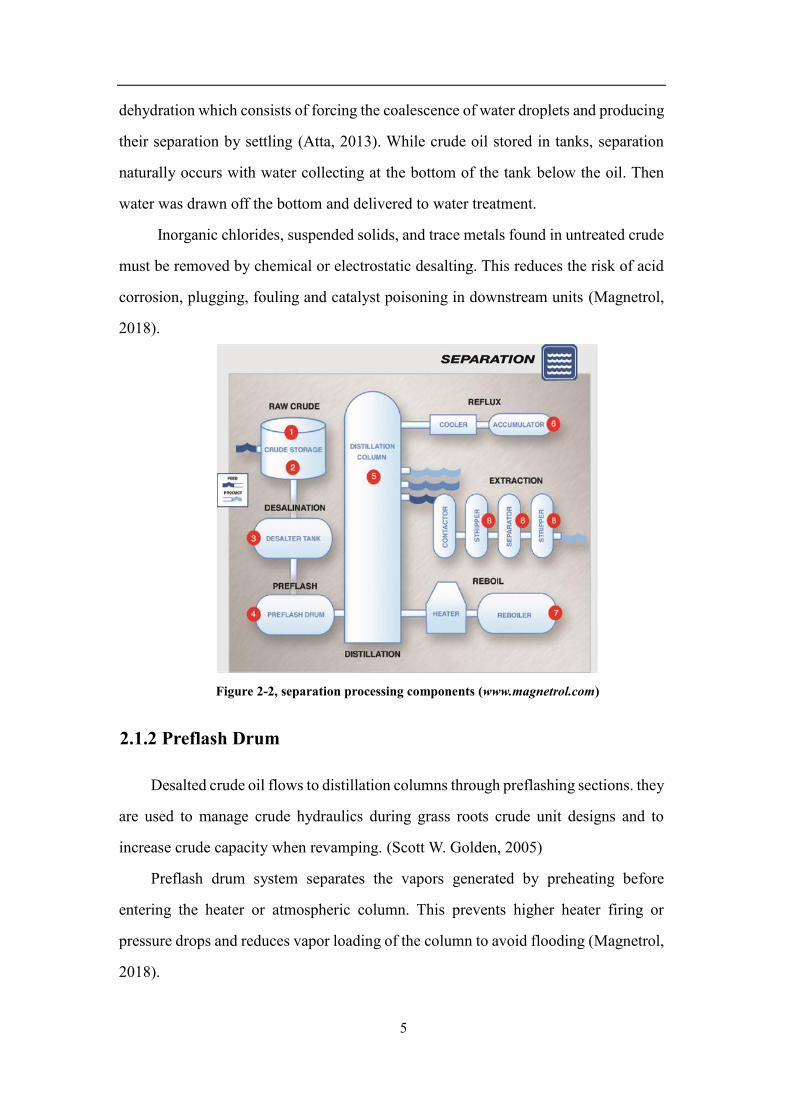
2.1 Separation
Crude oil is the naturally occurring liquid form petroleum. Once raw crude oil
arrives at the refinery terminal by pipeline or other transportations, they are pumped
into above-ground storage tanks which are floating roof or fixed roof tanks which are
floating roof or fixed roof tanks with capacities of thousands to millions of gallons.
2.1.1 Dewatering & Desalting
Petroleum is typically produced as a water-in-oil emulsion. The water must be
removed (down to a level of < 1 %) in a process usually called demulsification or
5
dehydration which consists of forcing the coalescence of water droplets and producing
their separation by settling (Atta, 2013). While crude oil stored in tanks, separation
naturally occurs with water collecting at the bottom of the tank below the oil. Then
water was drawn off the bottom and delivered to water treatment.
Inorganic chlorides, suspended solids, and trace metals found in untreated crude
must be removed by chemical or electrostatic desalting. This reduces the risk of acid
corrosion, plugging, fouling and catalyst poisoning in downstream units (Magnetrol,
2018).
Figure 2-2, separation processing components (www.magnetrol.com)
2.1.2 Preflash Drum
Desalted crude oil flows to distillation columns through preflashing sections. they
are used to manage crude hydraulics during grass roots crude unit designs and to
increase crude capacity when revamping. (Scott W. Golden, 2005)
Preflash drum system separates the vapors generated by preheating before
entering the heater or atmospheric column. This prevents higher heater firing or
pressure drops and reduces vapor loading of the column to avoid flooding (Magnetrol,
2018).

6
2.1.3 Distillation
It is also known as crude distillation unit(CDU) and vacuum distillation
unit(VDU), the crude is heated to vaporize at the column bottom with the temperature
of 350°C to 400°C. The vapors rise inside the column while heavy residuals remain at
the bottom which cannot be vaporizing. As the height rises inside the column, the
vapors becomes more and more light and has been collected to different trays. Only
gases reach the top, where the temperature dropped to 150°C.The heavy residuals left
after atmospheric distillation still contains many medium density products. The
residuals are transferred to the vacuum column where a second distillation is carried
out to recover the middle distillate, such as heavy fuel oil and diesel.
2.1.3.1 Distillation Column
Atmospheric distillation column (ADU) and Vacuum distillation column (VDU)
are the main primary separation processes and most important part of refinery, where
fractional distillation separates hydrocarbons into separate streams, cuts or fractions.
This process relay on the vapor pressure characteristics of liquid mixtures, and they
are consist of several components, each of them is used either to transfer heat energy
or reinforce material transfer.
A typical distillation contains several major components: 1. A vertical shell in which separation of liquid components 2. column internals such as trays, plates, packings, for enhance component
separations;
3. a reboiler to provide the necessary vaporization for the distillation process, this
improves separation by introducing more heat into the column. (M.T. Tham and
R.C. Costello, 2018);
4. a condenser to cool and condense the steam leaving the top of the column;
5. An accumulator for holding condensed steam at the top of the column so that
reflux can be recycled back to the column
7
2.1.3.2 Solvent Extraction
The heavy fraction remaining following the distillation of crudes is called
petroleum residuals. A variety of solvent-extraction processes yield deasphalted oil
from these residuals. These oils serve as downstream feedstocks for catalytic crackers
and hydrocrackers (James G,2006).
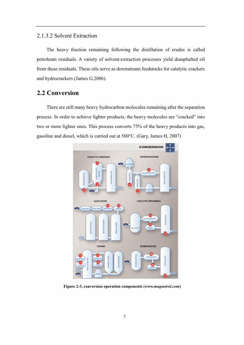
2.2 Conversion
There are still many heavy hydrocarbon molecules remaining after the separation
process. In order to achieve lighter products, the heavy molecules are “cracked” into
two or more lighter ones. This process converts 75% of the heavy products into gas,
gasoline and diesel, which is carried out at 500°C. (Gary, James H, 2007)
Figure 2-3, conversion operation components (www.magnetrol.com)
8
2.2.1 Catalytic Cracker
Fluid Catalytic Cracking Units (FCCUs) are a secondary conversion operation
within more complex refineries, and is used to produce additional gasoline, primarily,
from the gas oils produced in the atmospheric and vacuum distillation units. Its
chemical process utilizes a catalyst and heat to break long-chain hydrocarbons into
smaller-chain hydrocarbons. Typical products include gasoline, distillate, butane, and
propane fuels.
2.2.2 Hydrocracking
Hydrocracking is an important conversion technology where heavy feedstock is
cracked in the presence of hydrogen to produce high-value naphtha or distillate
products from a wide range of refinery feedstocks. This process employs high pressure,
high temperature, a catalyst and hydrogen.
2.2.3 Alkylation
Alkylation is a combining process that creates alkylate, a premium, high-octane
blending stock. The procedure is carried out under the catalysis of a strong acid such
as sulfuric acid or hydrofluoric acid. Storage and wash vessels in the alkylation unit
include those for fresh and depleted acid and water, an acid analyzer settling pot, and
a number of wash tanks. (Wikipedia, 2018)
2.2.4 Catalytic Reformer
Catalytic reforming is a chemical process used to convert petroleum
refinery naphthas distilled into high-octane liquid products called reformates, which
are premium blending stocks for high-octane gasoline. The dehydrogenation also
produces significant amounts of hydrogen gas as a byproduct, which is fed into other
refinery processes such as hydrocracking.

9
Catalytic reforming is similar to isomerization in that the hydrocarbon molecules
are rearranged.
2.2.5 Coking Operations
Coking is the final means of converting the heaviest products of atmospheric and
vacuum distillation which converts the residual oil from the vacuum distillation
column into low molecular weight hydrocarbon gases, naphtha, light/heavy gas oils,
and petroleum coke.
2.3 Treatment
Treating is the refining processes intended to remove unwanted compounds
(contaminants) from and improve the properties of certain products so that they meet
applicable standards. It involves removing or significantly reducing molecules that are
corrosive or cause air pollution, Like Sulphur, nitrogen, oxygen, metals, etc.
Figure 2-4, Treating operational system (www.magnetrol.com)

10
2.3.1 Hydro Desulfurization
Hydrodesulfurization (HDS) is a catalytic chemical process widely used to
remove sulfur from natural gas and from refined petroleum products, such as gasoline,
jet fuel, kerosene, diesel fuel, and fuel oils. The purpose of removing the sulfur, and
creating products such as ultra-low-sulfur diesel, is to reduce the sulfur dioxide (SO2)
emissions.
2.3.2 Chemical Storage
From acids to water treatment additives, a wide array of chemicals are stored at
warehouse in vessels that range in size from plastic totes to large steel tanks.
Chemicals such as sulfuric and hydrochloric acid, sodium hydroxide, liquid catalysts,
blending additives and water treatment chemicals.
2.4 Blending.
Blending is mixing of HCs in certain fractions to obtain finished products with
specific properties.
Figure 2-5, Blending component (www.magnetrol.com)

11
2.4.1 Blending Unit
A facility which has no refining capability but is either capable of producing
finished motor gasoline through mechanical blending or blends oxygenates with motor
gasoline. The objective of product blending is to assign all available blend components
to satisfy the product demand and specifications to minimize cost and maximize
overall profit. For example, typical motor gasolines may consist of straight-run
naphtha from distillation, crackate (from FCC), reformate, alkylate, isomerate, and
polymerate, in proportions to make the desired grades of gasoline and the
specifications.
2.4.2 Finished Products and Their Uses
Finished refinery products are motor gasoline, jet fuel, diesel fuel, fuel oils, and
LPG, stored in tanks with capacities that often exceed 100,000 gallons.
Each refined petroleum product obtained from crude oil has a specific use:
1. Liquefied petroleum gas (LPG), also known as butane and propane, is used as an
automotive fuel or packaged in bottles and used for household purposes.
2. Gasoline and diesel are used as fuels for motor vehicles.
3. Kerosene is used as jet fuel.
4. Naphtha is a major petrochemical feedstock.
5. Heating oil is used to heat buildings.
6. Base oils are used to make lubricants.
7. Bitumen, is used to pave roads. (Planete energies, 2015).
12
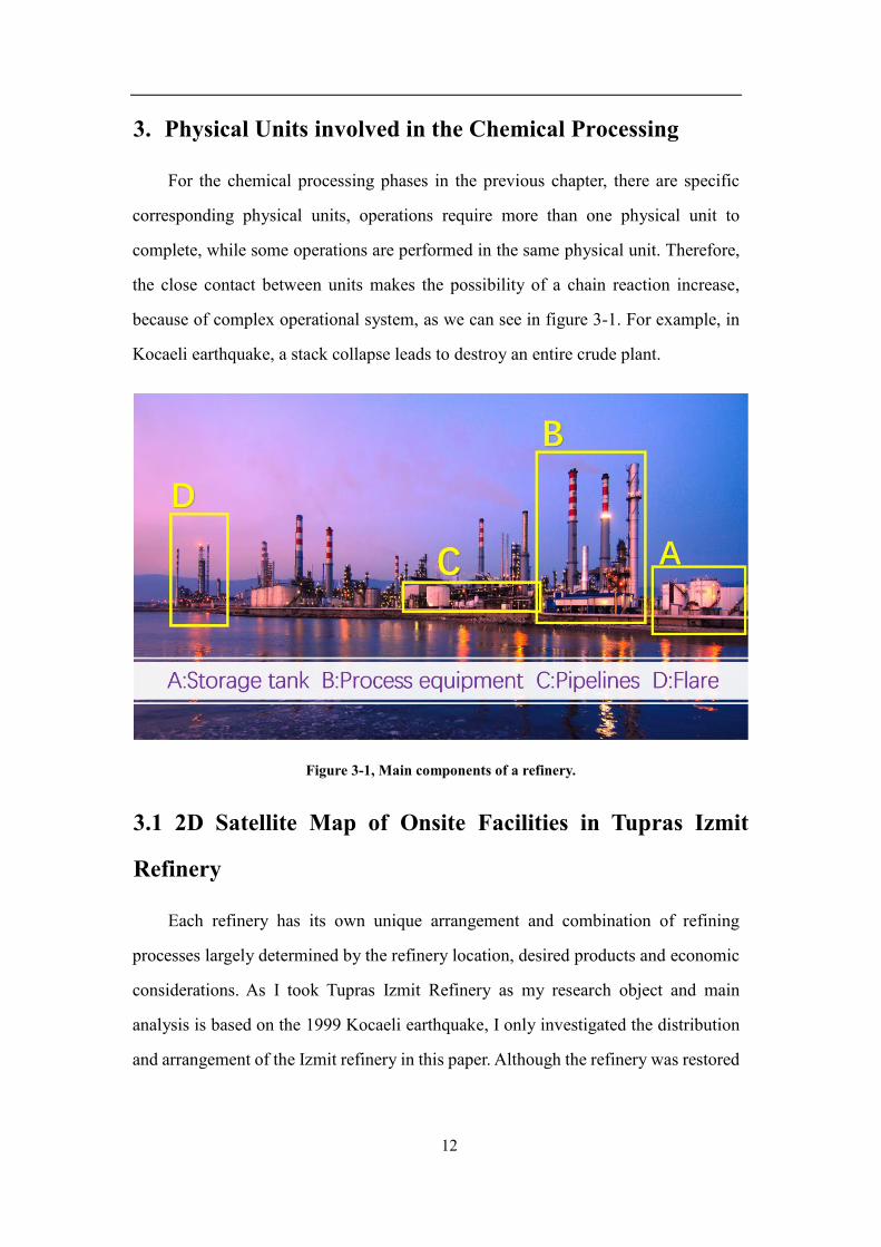
3. Physical Units involved in the Chemical Processing
For the chemical processing phases in the previous chapter, there are specific
corresponding physical units, operations require more than one physical unit to
complete, while some operations are performed in the same physical unit. Therefore,
the close contact between units makes the possibility of a chain reaction increase,
because of complex operational system, as we can see in figure 3-1. For example, in
Kocaeli earthquake, a stack collapse leads to destroy an entire crude plant.
Figure 3-1, Main components of a refinery.
3.1 2D Satellite Map of Onsite Facilities in Tupras Izmit
Refinery
Each refinery has its own unique arrangement and combination of refining
processes largely determined by the refinery location, desired products and economic
considerations. As I took Tupras Izmit Refinery as my research object and main
analysis is based on the 1999 Kocaeli earthquake, I only investigated the distribution
and arrangement of the Izmit refinery in this paper. Although the refinery was restored
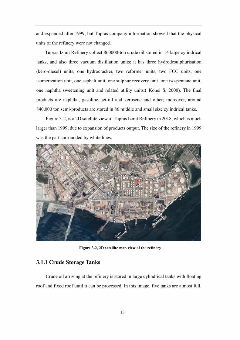
13
and expanded after 1999, but Tupras company information showed that the physical
units of the refinery were not changed.
Tupras Izmit Refinery collect 860000-ton crude oil stored in 14 large cylindrical
tanks, and also three vacuum distillation units; it has three hydrodesulphurisation
(kero-diesel) units, one hydrocracker, two reformer units, two FCC units, one
isomerization unit, one asphalt unit, one sulphur recovery unit, one iso-pentane unit,
one naphtha sweetening unit and related utility units.( Kohei S, 2000). The final
products are naphtha, gasoline, jet-oil and kerosene and other; moreover, around
840,000 ton semi-products are stored in 86 middle and small size cylindrical tanks.
Figure 3-2, is a 2D satellite view of Tupras Izmit Refinery in 2018, which is much
larger than 1999, due to expansion of products output. The size of the refinery in 1999
was the part surrounded by white lines.
Figure 3-2, 2D satellite map view of the refinery
3.1.1 Crude Storage Tanks
Crude oil arriving at the refinery is stored in large cylindrical tanks with floating
roof and fixed roof until it can be processed. In this image, five tanks are almost full,

14
six are half-full and five are almost empty, and nine fixed roof tanks cannot tell the
capacity.
Figure 3-3, 2D satellite map view of storage tanks
3.1.1.1 Floating Roof Tanks
Floating roofs are widely used to store petroleum products with high volatility.
This is to prevent the product loss and to ensure safe environment around the storage
tanks (Mohamed. A & Ghorab 2016). The floating top gives an indication of the
volume of oil contained within the tank. They are more ideal for lay in large quantities
of crude oil. Crude oil liberates volatile natural gas and also some air pollutants, vapors
could cause explosions and fires, so it’s good for them to be contained in the space
that is between the roof and liquids, and the vapors could be released according to the
condition.
Figure 3-4, Floating roof & Fixed roof tank model (Antonio Di Carluccio, 2007)

15
3.1.1.2 Fixed Roof Tanks
Fixed roof tanks are suitable for liquids with very high flash points, such as water
and fuel oil. Cone roofs, dome roofs and umbrella roofs are usual. These are insulated
to prevent the clogging of certain materials, where in the heat is provided by steam
coils within the tanks (API Standard 653, 1995).
3.1.2 Processing Area
Crude Oil is a mix of different hydrocarbons known as fractions. In the
processing area these fractions are refined into a variety of products by
separation/distillation, catalytic conversion, treatment and blending etc. There are four
processes used in Tupras Izmit refinery to transform crude oil into a variety of useful
goods and delivered by pipeline systems.
1. Fractionation of crude oil molecules by size. (Crude atmospheric & Vacuum
Distillation)
2. Breaking larger molecules into smaller one. (Fluid Catalytic Cracking)
3. Combining smaller molecules into larger one. (Alkylation)
4. Changing the shapes of molecule. (Catalytic Reforming)
Figure 3-5, 2D satellite map view of processing area

16
3.1.3 Semi-refined and Refined Storage
After processing, the refined products are stored in cylindrical tanks with floating,
flat, domed or peaked tops. These tanks are generally much smaller than crude oil
storage tanks. Finished products are Gasoline, Jet and Heating Fuels, Liquefied
Petroleum Gas, Chemicals.
Figure 3-6, 2D satellite map view of finished products tanks
3.1.4 Gas Storage Tank (spherical Storage Tanks)
Gas store is different to other refined products, stored under pressure in specially-
designed spherical, spheroidal, blimp or bullet-shaped tanks. In Izmit refinery, they
are designed as spherical storage tank which is built with less pieces of material and
has fewer welded connection points.There are no damage happened to this kind of
tank in 1999 Izmit earthquake.
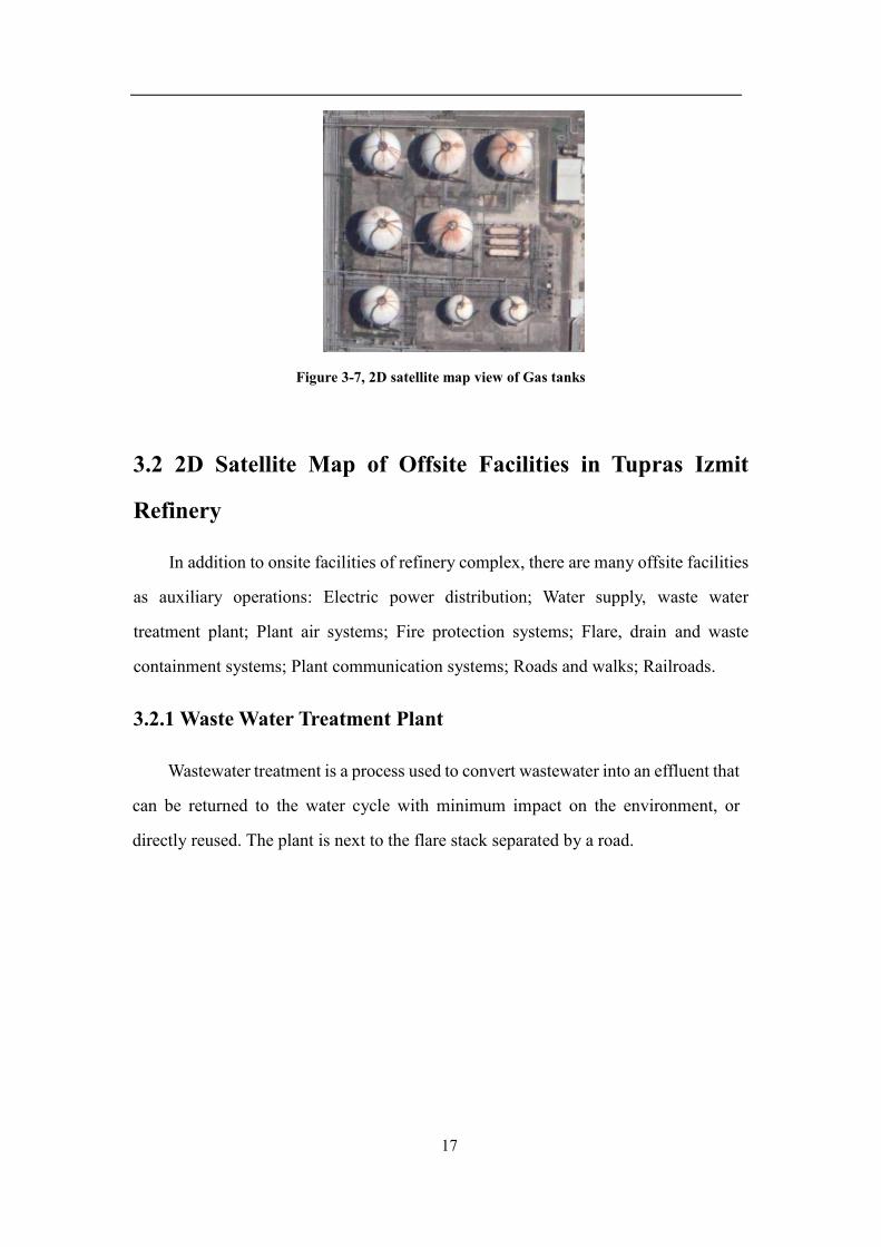
17
Figure 3-7, 2D satellite map view of Gas tanks
3.2 2D Satellite Map of Offsite Facilities in Tupras Izmit
Refinery
In addition to onsite facilities of refinery complex, there are many offsite facilities
as auxiliary operations: Electric power distribution; Water supply, waste water
treatment plant; Plant air systems; Fire protection systems; Flare, drain and waste
containment systems; Plant communication systems; Roads and walks; Railroads.
3.2.1 Waste Water Treatment Plant
Wastewater treatment is a process used to convert wastewater into an effluent that
can be returned to the water cycle with minimum impact on the environment, or
directly reused. The plant is next to the flare stack separated by a road.

18
Figure 3-8, 2D satellite map view of waste water treatment
3.2.2 Energy Generation Unit (Electric power distribution)
An oil refinery uses a lot of electrical and steam power to drive pumps,
compressors and control center. For this reason it requires its own power station,
independent of the national grid.
Figure 3-9, 2D satellite map view of Electric power distribution
3.2.3 Flare Stack
Waste gases produced during processing are burnt off by a safety device known
as a flare stack. This has a pilot light burning continuously at the top; if a flame is
observed on imagery it indicates high activity within the processing area.
19
Figure 3-10, 2D satellite map view of flare stack
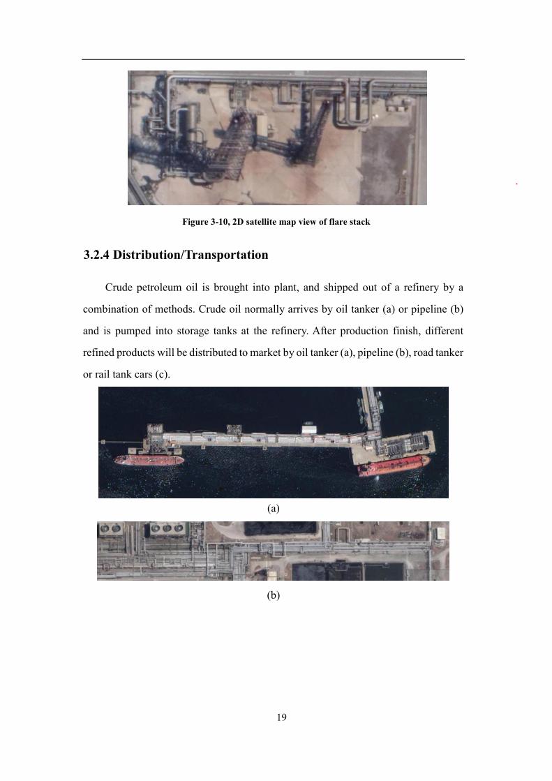
3.2.4 Distribution/Transportation
Crude petroleum oil is brought into plant, and shipped out of a refinery by a
combination of methods. Crude oil normally arrives by oil tanker (a) or pipeline (b)
and is pumped into storage tanks at the refinery. After production finish, different
refined products will be distributed to market by oil tanker (a), pipeline (b), road tanker
or rail tank cars (c).
(a)
(b)
20
(c)
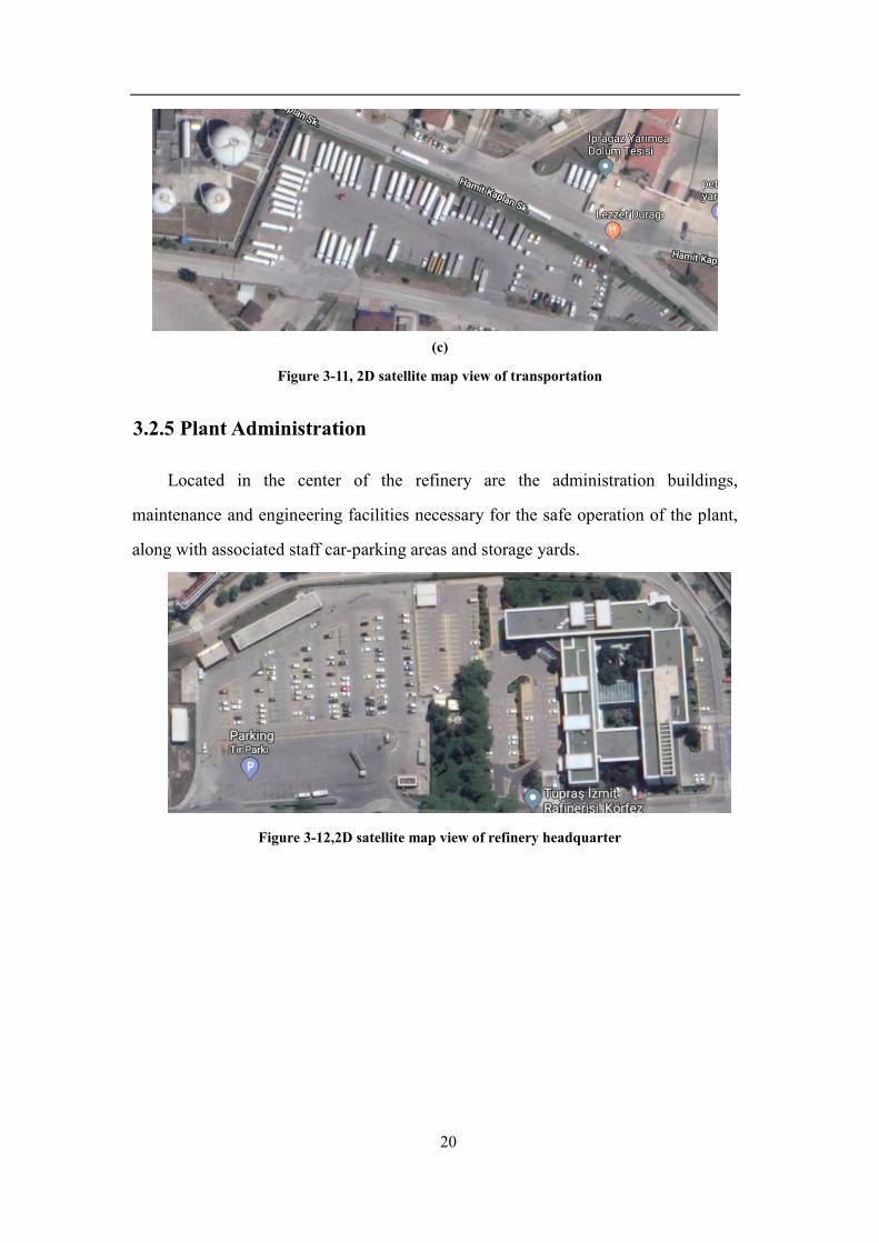
Figure 3-11, 2D satellite map view of transportation
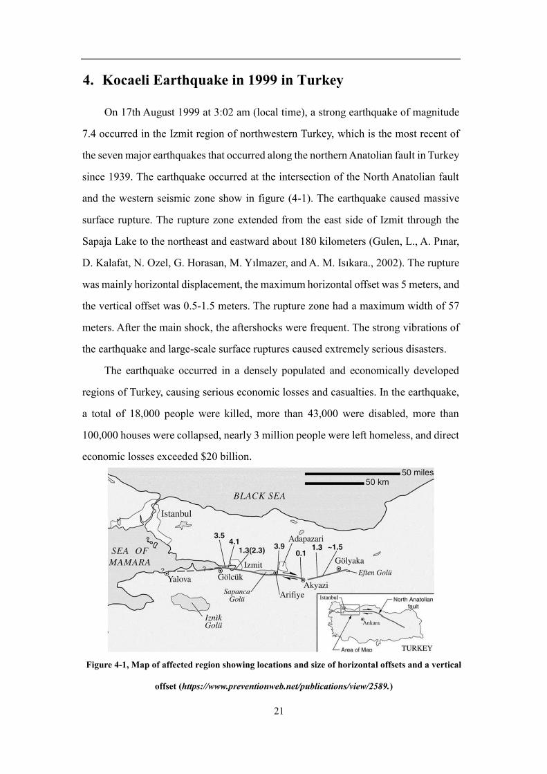
3.2.5 Plant Administration
Located in the center of the refinery are the administration buildings,
maintenance and engineering facilities necessary for the safe operation of the plant,
along with associated staff car-parking areas and storage yards.
Figure 3-12,2D satellite map view of refinery headquarter
21
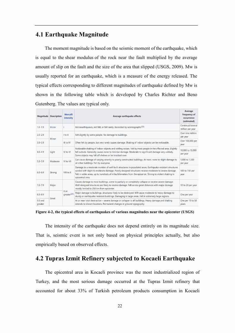
4. Kocaeli Earthquake in 1999 in Turkey
On 17th August 1999 at 3:02 am (local time), a strong earthquake of magnitude
7.4 occurred in the Izmit region of northwestern Turkey, which is the most recent of
the seven major earthquakes that occurred along the northern Anatolian fault in Turkey
since 1939. The earthquake occurred at the intersection of the North Anatolian fault
and the western seismic zone show in figure (4-1). The earthquake caused massive
surface rupture. The rupture zone extended from the east side of Izmit through the
Sapaja Lake to the northeast and eastward about 180 kilometers (Gulen, L., A. Pınar,
D. Kalafat, N. Ozel, G. Horasan, M. Yılmazer, and A. M. Isıkara., 2002). The rupture
was mainly horizontal displacement, the maximum horizontal offset was 5 meters, and
the vertical offset was 0.5-1.5 meters. The rupture zone had a maximum width of 57
meters. After the main shock, the aftershocks were frequent. The strong vibrations of
the earthquake and large-scale surface ruptures caused extremely serious disasters.
The earthquake occurred in a densely populated and economically developed
regions of Turkey, causing serious economic losses and casualties. In the earthquake,
a total of 18,000 people were killed, more than 43,000 were disabled, more than
100,000 houses were collapsed, nearly 3 million people were left homeless, and direct
economic losses exceeded $20 billion.
Figure 4-1, Map of affected region showing locations and size of horizontal offsets and a vertical
offset (https://www.preventionweb.net/publications/view/2589.)
22
4.1 Earthquake Magnitude
The moment magnitude is based on the seismic moment of the earthquake, which
is equal to the shear modulus of the rock near the fault multiplied by the average
amount of slip on the fault and the size of the area that slipped (USGS, 2009). Mw is
usually reported for an earthquake, which is a measure of the energy released. The
typical effects corresponding to different magnitudes of earthquake defined by Mw is
shown in the following table which is developed by Charles Richter and Beno
Gutenberg. The values are typical only.
Figure 4-2, the typical effects of earthquakes of various magnitudes near the epicenter (USGS)
The intensity of the earthquake does not depend entirely on its magnitude size.
That is, seismic event is not only based on physical principles actually, but also
empirically based on observed effects.
4.2 Tupras Izmit Refinery subjected to Kocaeli Earthquake
The epicentral area in Kocaeli province was the most industrialized region of
Turkey, and the most serious damage occurred at the Tupras Izmit refinery that
accounted for about 33% of Turkish petroleum products consumption in Kocaeli

23
Province of Turkey. It started production in 1961, with a 1 million tons/year capacity of
crude oil processing. As the result of significant capacity augmentation and investments
over the years, its design capacity was registered at 11.0 million tons per year (Tupras,
2010). The earthquake caused a large number of structural damages and collapse of the
refinery, resulting in the failure of rescue activities. And a series of chain reactions
occurred in the refinery,such as tank farm fires, stack collapse, crude unit, oil spill and
so on.
Figure 4-3, Plan view of Izmit refinery in 1999 and location of damage facilities.(Kohei Suzuki,
2000)
4.2.1 Fires Caused by Earthquake
Shortly after the earthquake, fires started simultaneously at three different
locations in the refinery which are chemical warehouse fire, plant 25 fire, and the
naphtha tank farm fire.
The first fire occurred in the chemical warehouse shortly after the earthquake, it
was quickly extinguished due to limited size. The second fire started at the crude-oil
processing plant, the fire was very fierce and finally extinguished after a dozen hours
of rescue efforts. It was caused by a concrete chimney heater collapse. The third and

24
the largest fire occurred at the naphtha tank farm, which is located approximately at
the center of the tank farm area of the refinery, that you can see the tank damaged
sample by fire in figure 4-6. The fire in a naphtha tank farm was considered to be
initiated by sparks created by bouncing of the floating roof against the inner walls of
the tank during the earthquake. There were 46 tanks with floating roofs, most of which
were built in the early 1960s according to the California Earthquake Design Code.
Besides cylindrical tanks, there were also some spherical tanks for gas storage. None
of these were damaged.
Although fires following the earthquake were major issues in this event, there
were other kinds of hazards happened and triggered to tank farm fire, for example,
tank collapses, “sinking” of floating roofs, tank elephant feet, stack collapse, water
supply line breaks, oil spill, pipeline collapse, cooling tower collapse, pile damage at
port.
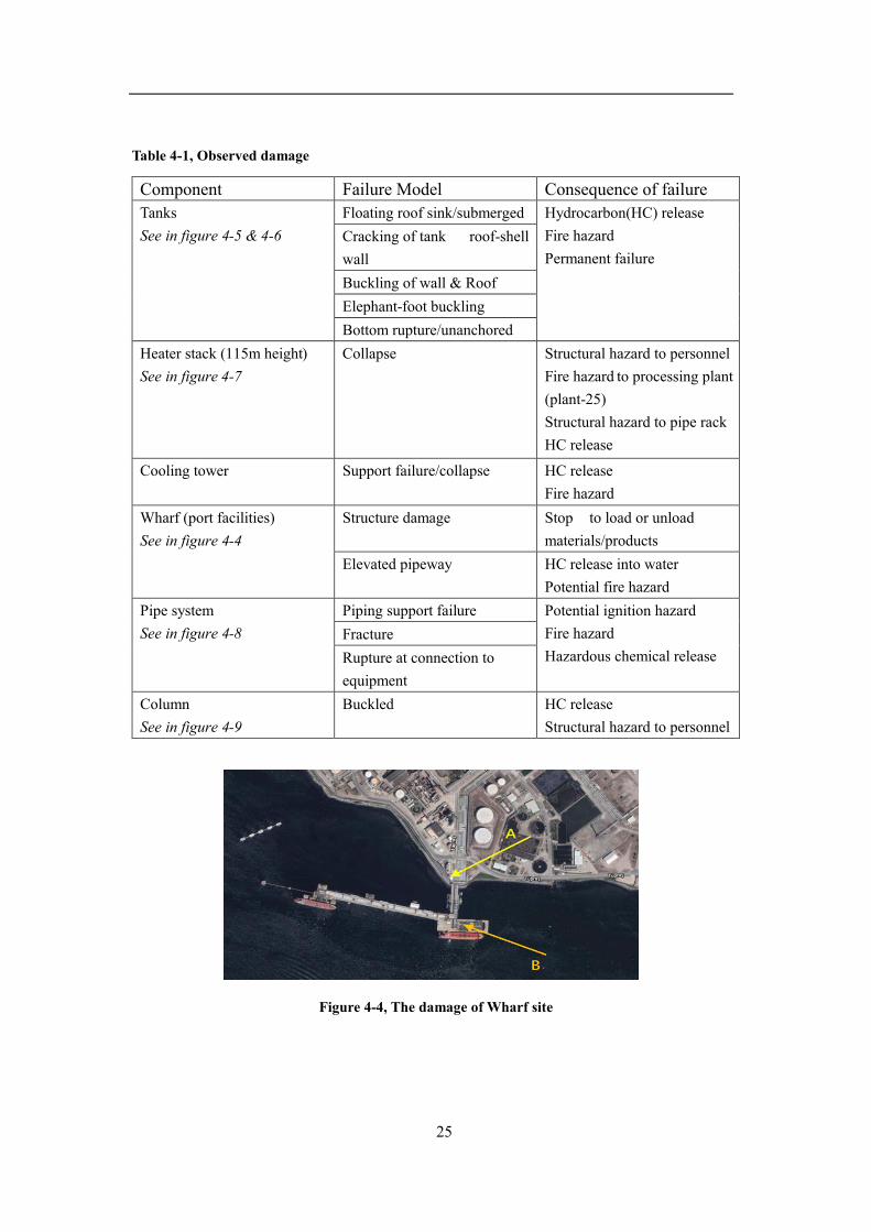
4.2.2 Observed Damage
In the refinery, many mechanical equipment and building structures were
damaged, which not only caused huge economic losses, but also caused serious
damage to the environment (Kohei S,2000). There is a table below summarizes the
damage.
25
Table 4-1, Observed damage
Figure 4-4, The damage of Wharf site
Component Failure Model Consequence of failure Tanks See in figure 4-5 & 4-6
Floating roof sink/submerged Hydrocarbon(HC) release Fire hazard Permanent failure
Cracking of tank roof-shell wall Buckling of wall & Roof Elephant-foot buckling Bottom rupture/unanchored
Heater stack (115m height) See in figure 4-7
Collapse Structural hazard to personnel Fire hazard to processing plant (plant-25) Structural hazard to pipe rack HC release
Cooling tower Support failure/collapse HC release Fire hazard
Wharf (port facilities) See in figure 4-4
Structure damage Stop to load or unload materials/products
Elevated pipeway HC release into water Potential fire hazard
Pipe system See in figure 4-8
Piping support failure Potential ignition hazard Fire hazard Hazardous chemical release
Fracture Rupture at connection to equipment
Column See in figure 4-9
Buckled HC release Structural hazard to personnel
26
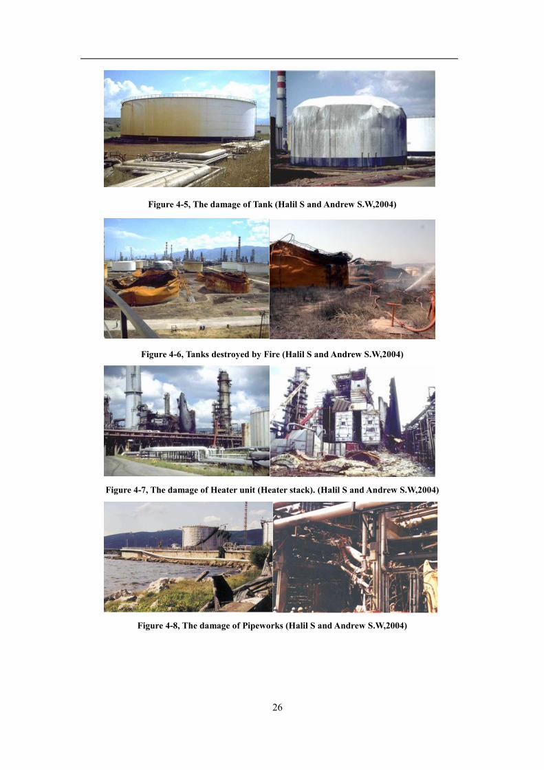
Figure 4-5, The damage of Tank (Halil S and Andrew S.W,2004)
Figure 4-6, Tanks destroyed by Fire (Halil S and Andrew S.W,2004)
Figure 4-7, The damage of Heater unit (Heater stack). (Halil S and Andrew S.W,2004)
Figure 4-8, The damage of Pipeworks (Halil S and Andrew S.W,2004)
27
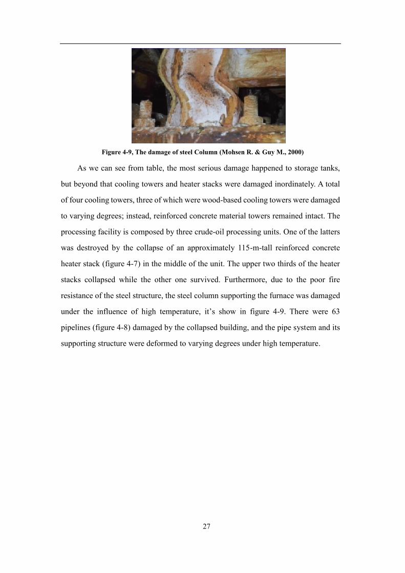
Figure 4-9, The damage of steel Column (Mohsen R. & Guy M., 2000)
As we can see from table, the most serious damage happened to storage tanks,
but beyond that cooling towers and heater stacks were damaged inordinately. A total
of four cooling towers, three of which were wood-based cooling towers were damaged
to varying degrees; instead, reinforced concrete material towers remained intact. The
processing facility is composed by three crude-oil processing units. One of the latters
was destroyed by the collapse of an approximately 115-m-tall reinforced concrete
heater stack (figure 4-7) in the middle of the unit. The upper two thirds of the heater
stacks collapsed while the other one survived. Furthermore, due to the poor fire
resistance of the steel structure, the steel column supporting the furnace was damaged
under the influence of high temperature, it’s show in figure 4-9. There were 63
pipelines (figure 4-8) damaged by the collapsed building, and the pipe system and its
supporting structure were deformed to varying degrees under high temperature.

28
5. Risk Factors of a Petrochemical Plant subjected to Seismic
Load
From the above seismic damage analysis, it is found that the damage caused by
the earthquake to the petrochemical plant is unbearable. Moreover, the consequences
of such damage are enormous, which will not only cause major economic losses to the
production enterprises, endanger the safety of the workers, but also cause devastating
secondary disasters (Masayoshi N and Oren L, Nakashima, M., Lavan, O., Kurata, M.
et al., 2014). Therefore, in order to ensure the safety of such projects such as
petrochemical plants, necessary engineering measures and monitoring program must
be taken to mitigate direct and secondary disasters; as well an effective communication
and a correct education to communities living surrounding petrochemical plant.
5.1 Structures Design
Earthquakes cause devastating disasters for structures. At the same time, cracks
in structures and even collapse of buildings cause huge casualties and economic losses
to the country. Therefore, we should continuously optimize the structural design by
observing the failure mode of buildings subjected to earthquake to reduce structural
damage in the future.
The main reason for the destruction of structures is that seismic waves propagate
in the soil and cause strong ground motion. The damage is manifested in the
destruction of ground facilities, or the failure of foundations. The damage caused by
secondary effects also endanger the construction. Large-size structures such as
refineries are often more devastated during earthquake. Although earthquakes are
natural disasters, with the development of science and technology, effective measures
can greatly reduce the losses caused by earthquakes. Since the first half of the
twentieth century, seismic engineering research and development for refineries has
received extensive attention, including the development of new materials, new
structural designs, and so on. For example, Alloy 33 which is a new corrosion resistant
29
austenitic material for the refinery industry and anti-seismic flexible joint are
innovatively applied (2012). These valuable research presented a huge step forward in
understanding earthquake hazard mitigation, which resulted in appreciable reduction
of the effects of past earthquakes. The Sendai refinery in Japan officially put into
operation in 1971. The refinery is located in Miyagi Prefecture, Japan, where
earthquakes occur throughout the year. Since its establishment, the refinery has always
emphasized safety first and has good safety measures. The refinery absorbed the
lessons of the Great Hanshin Earthquake in 1995 and continuously optimized the
design of the structure, attaching great importance to the seismic design, material
selection and construction of new equipment. The post-construction structure is based
on the new national seismic standards of Japan, which improves the seismic
requirements and basically withstands the test of the earthquake. Especially in 2003,
a magnitude 7 earthquake occurred in Sendai City, and the refinery did not suffer
damage. Moreover, from the above damage analysis of Tupras Izmit Refinery, if
structural damage is reduced, damages caused by the earthquake are greatly reduced.
For example, if the floating roof and walls of the storage tanks use dissipative spacers
to reduce the collision between them, the damage of the storage tank will be reduced
and the fire will not develop rapidly. In the end, the destruction of this refinery will
not be so serious. Therefore, it also proves that structural seismic design is an
important measure to reduce earthquake disasters.
5.1.1 Storage Tank
Seismic provision of all types of structures integrating the petrochemical plant is
of paramount importance in regions subjected to medium and high seismic hazard.
This is especially true for steel storage tanks, which typically contain toxic, flammable
and explosive materials. Moreover,special attention should be paid to the seismic
design of steel storage tanks, because these structures are very specific and have
certain features that make their behavior particularly different from that of a building.
Storage facilities are presented by a variety of members whose size, shape, operating

30
pressure and temperature, functional requirements and characteristics vary. Each type
has its own analysis, design and detail criterion . In addition, steel storage tanks are
part of special facilities related to national security and defence. In the 1960s, US
contractors built the Tupras refinery in accordance with US standards, and the storage
tanks were designed according to UBC which is called API650 in nowadays. In recent
years, with the development of science and technology, API650 has been continuously
revised to meet the seismic needs of oil storage tank structures. Many historical
earthquakes indicate that oil storage tanks are the most severely affected equipment in
petrochemical equipment. Incidents with storage facilities around the world as a result
of seismic activity are not uncommon. Some of the most severe cases happened in
Chile in 1960, USA: Alaska 1964; Japan: Niigata 1964 and Tokachi in 2003. Lighter
incidents are more common, will not make the statistics in this paper.
There are several types of earthquake disasters in oil storage tanks: damage to the
pipe wall, damage to the roof of the tank and instability of the upper tank wall, joints
of the structure and damage of the weld seam, and uneven settlement of the foundation.
At present, there are many methods for reducing the earthquake damage of oil storage
tanks. For example, as shown in Figure 5-1, for structural buckling failure of the tank
wall, structural engineers optimized the structural design by placing steel bars on the
outside of the tank to withstand greater bending moments after the Kocaeli earthquake.
In response to the severely damaged floating roof storage tanks, not only new
construction forms, but also sufficient fire-fighting equipment are provided. Moreover,
typical observed damages (failure of wall-bottom plate welding, elephant foot
buckling, elastic buckling of wall, settlements of the ground under the tank) can be
eliminated using base isolation technique (Paolacci, 2012). Other accidents and
possible damages due to sloshing motion in presence of floating roof, are neither
amplified nor reduced by the isolation. A possible solution to reduce the effects of the
impact between floating roof and tank wall can be represented by spacers placed
between roof and wall or by inserting a TMD system into the roof (Paolacci, 2012).

31
However, in order to reduce the damage caused by the earthquake to the oil
storage tank, we still have a lot of work to do in the future, mainly including the
following aspects. First of all, we should use materials with high strength, toughness
and good seismic performance and high-fire resistance. Secondly, improve the
construction and design method of the structure to ensure the strength and rigidity of
the structure and increase the plastic deformation of the oil storage tank under the
action of cyclic loading; thirdly, the necessary energy-consuming devices and
reinforcement methods should be used so that structural bearing capacity is improved
and the response under earthquake is reduced.
Figure 5-1, Retrofitting on the naphtha tank TK-202 burned during the fire.(Girgin 2011)
5.1.2 Other Structures
From the perspective of the damage of the cooling tower, it is not difficult to find
that the seismic performance of reinforced concrete structure is higher than that of the
wood. Moreover, in the event of a fire, reinforced concrete has strong fire resistance.
Therefore, in order to improve the performance of the structure, the cooling tower
should be made of reinforced concrete. By above mentioned earthquake scenes, we
can see that the impact of stack collapse is also huge. The fall of heavy concrete causes
irreparable damage to the surrounding equipment, especially the damage of the
pipeline system, causing leakage of toxic liquids, contributing to the spread of the fire,
and posing great obstacles to rescue operations. For structures with large slenderness

32
ratio, under the action of earthquakes, large displacements occur in the upper part of
the structure or overturning damage occurs in the whole structure, which leads to
failure of the flange connection or yielding of the anchoring steel at the bottom of the
structure. In this case, the most appropriate passive control technique appears to be
dissipation coupling between blood vessels and adjacent structures (Paolacci, 2012).
Taking corresponding measures, the damage of pipe system, attached to the stack, will
be reducted and the fire will not be so fierce.
It can be seen that studying the seismic design of structures is very important.
Firstly, for such a major structure, we should carry out a rigorous structural design to
resist the horizontal forces generated by the earthquake. Secondly, high performance
materials and energy absorbing devices can be used to mitigate the effects of
earthquakes on the structure. Moreover, supervision should be carried out during the
construction process to ensure the quality of the structure. Finally, it is important to
have appropriate fire protection measures for the structure.
5.1.3 Equipment
In the Tupras Izmit refinery, pipes of various calibers and materials connect
thousands of units to complete the transportation of the medium. These pipes are
crisscrossed and versatile. In a medium-sized refinery, the cumulative length of
various pipelines can reach thousands of miles, so the pipeline is the key to the normal
operation of the refinery. The design of these pipelines not only affects economics,
rationality and aesthetics, but also relates to the construction, production and
maintenance of the entire refinery.
However, from the damage of Tupras Izmit Refinery, we found that due to the
action of the earthquake, the pipe will vibrate and tilt, which will cause damage to the
pipe joint and collapse of the pipe itself. In particular, the metallurgical pipes
themselves are not particularly vulnerable to seismic actions, but they can suffer the
effects of differential displacements, which may not be compatible with the permitted
deformations. Moreover, such damage may magnify the hazards of the earthquake and
33
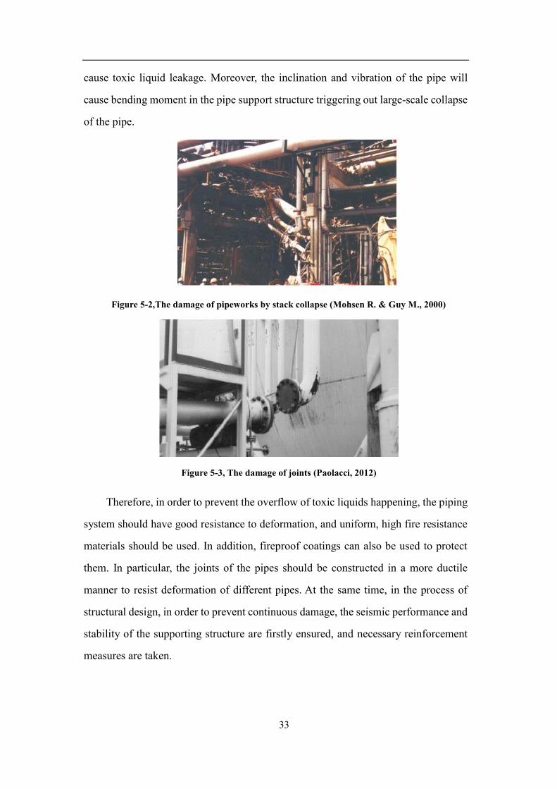
cause toxic liquid leakage. Moreover, the inclination and vibration of the pipe will
cause bending moment in the pipe support structure triggering out large-scale collapse
of the pipe.
Figure 5-2,The damage of pipeworks by stack collapse (Mohsen R. & Guy M., 2000)
Figure 5-3, The damage of joints (Paolacci, 2012)
Therefore, in order to prevent the overflow of toxic liquids happening, the piping
system should have good resistance to deformation, and uniform, high fire resistance
materials should be used. In addition, fireproof coatings can also be used to protect
them. In particular, the joints of the pipes should be constructed in a more ductile
manner to resist deformation of different pipes. At the same time, in the process of
structural design, in order to prevent continuous damage, the seismic performance and
stability of the supporting structure are firstly ensured, and necessary reinforcement
measures are taken.
34
5.2 Real-time Monitoring
Although the occurrence of an earthquake is inevitable, an efficient and rapid
real-time monitoring system is fundamental to reducing the loss of human lives and
leading the rescue teams quickly to the right place. In the Tupras Izmit refinery,
although earthquakes and fires caused huge damage to the building structure, and
caused incalculable damage to the surrounding natural environment. Fortunately, the
accident did not cause casualties, mainly due to the good real-time monitoring system.
In addition, a 7.3-magnitude earthquake occurred in Haicheng, Liaoning Province,
China in 1975. Haicheng is an industrially concentrated and densely populated area.
According to previous seismic data analysis, if the earthquake is not successfully
predicted, the number of casualties will reach 150,000 or more. Due to accurate real-
time monitoring, the government organized the mass to prevent which reduced the
number of casualties was greatly, resulting in a total of 18,308 casualties. In 2008, a
7.2-magnitude earthquake struck Iwate Prefecture, Japan, killing only 7 people and
injuring more than 100 people. At the time of the earthquake, Japan’s real-time
monitoring system played an important role in effectively reducing casualties and
losses. Therefore, in order to reduce the damage caused by earthquakes to the refinery
in the future, we should adopt a more perfect real-time monitoring system. In particular,
real-time prediction and real-time prevention are effective in reducing the damage
caused by earthquakes, and taking corresponding actions quickly, and have important
significance for post-earthquake recovery work. For this purpose, more advanced
sensing and monitoring technologies as well as theory for an immediate condition
assessment and structural health evaluation are essential.
5.2.1 Real-time Prediction
So-called real-time prediction: sensing the event parameters of an earthquake and
predicting the impact of the earthquake. Before the earthquake occurs, the detailed
information of the earthquake will be predicted in a short time, and appropriate
35
measures can be taken to minimize the impact of the disaster. In addition, real-time
forecasting can exercise the system's crisis management capabilities. Therefore, real-
time prediction is very important and is the basis for real-time prevention and crisis
management. When a disaster occurs, real-time forecasting can convey the latest news
to the government, company, organization, etc., which is conducive to better overall
planning. Moreover, for individuals, obtaining real-time seismic information
facilitates action and reduces the number of casualties caused by the earthquake.
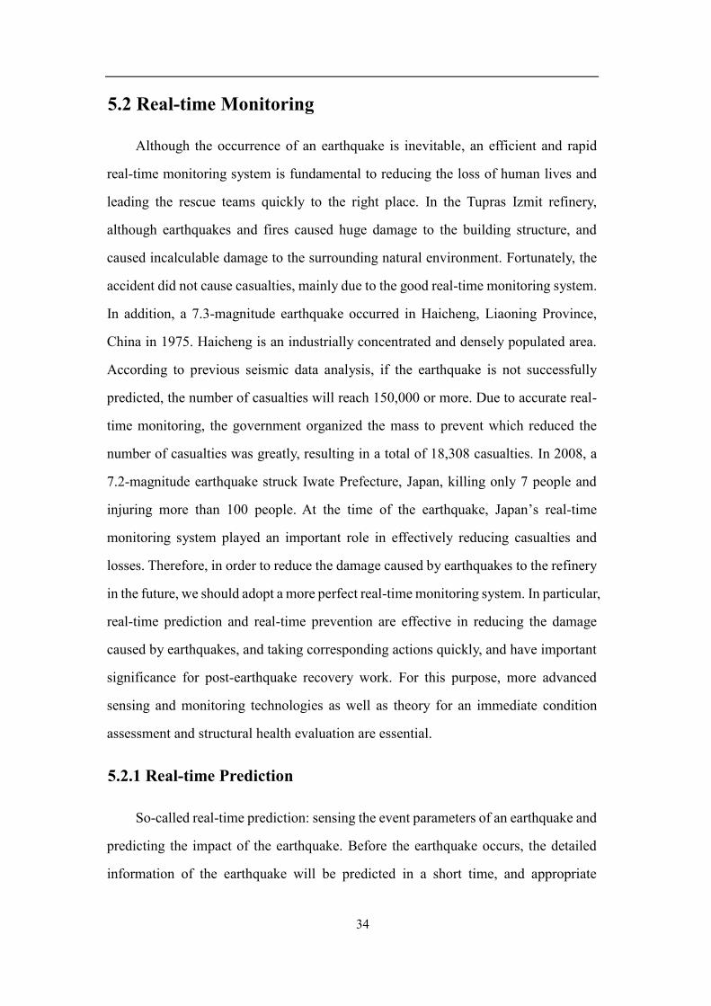
Prediction of ground motions and the corresponding structural response is a
crucial step in preparedness and response. Based on the seismic response acceleration
spectrum, the maximum force on the structure is derived. Accurately predicting the
time, location and magnitude of earthquake by seismic devices, like accelograms in
Figure 5-4, and conducting short-term earthquake predictions is also the most
economical way to mitigate earthquake disasters and is the goal of seismologists
around the world. For example, real-time prediction system also played a role in the
2011 East China Sea earthquake, which enabled 27 pairs of Shinkansen trains running
between the Tohoku region and Tokyo to stop braking and avoid further losses. At
present, countries around the world are aware of the importance of real-time prediction
systems and are constantly innovating in this field. For example, the self-developed
ICL earthquake early warning technology system in China has accurately predicted 18
destructive earthquakes and reduced huge losses.
Figure 5-4, Seismic accelerogram (Sezen and Whittaker 2006)
36
5.2.2 Real-time Prevention
With real time prediction at hand, real time prevention could be made possible.
Real time prevention refers here to early warning systems as well as shut down
systems for functions where damage may endanger a large population (e.g., nuclear
power plants, plants working with hazardous materials, etc.). After an immediate
feedback warning system, an advanced emergency system technology is capable of
remotely shutting down operation of every single unit in the event. And also an
accurate emergency security response could be supported by an emergency operations
support system promptly. After years of study seismic activity to lifelines, there are
many real-time prevention methods for reduce the disaster caused by earthquakes. For
example, SUPREME by company Tokyo Gas which is a ultrahigh density real-time
earthquake disaster prevention system for the prevention of secondary disasters related
to gas leakage when a major earthquake occurs, this system is capable of utilizing data
collected to estimate damage to gas pipeline networks in about 10 minute span
following the occurrence of an earthquake. And the earthquake data collected by
SUPREME system is sent to employees’ mobile phone within minutes of an
earthquake, is used to confirm the safety (Tokyo Gas Site, 2018). With the continuous
occurrence of the earthquake disaster in the chemical industry in recent years,
engineers have designed and developed many prevention systems. Although these
systems have greatly reduced disasters, it is still difficult to be close to zero disasters
due to the difficult to predictive of earthquakes.
5.3 Post-earthquake Environment
Based on the previous description and analysis, we know that the damage caused
by the earthquake to the refinery is devastating.
37
5.3.1 Post-earthquake Buildings State Evaluation
The main tasks of the post-earthquake building emergency assessment include:
assessing important buildings, seeing whether there is a risk of collapse for buildings
that have not collapsed, other hidden dangers, and the evacuation of the building and
its surroundings.
In the face of natech-events, such as earthquakes, people are often caught off
guard. Earthquake prediction and assessment work is particularly important, but
because of the current science and technology, it is often impossible to effectively
inform people of the earthquake in advance, so that people can prepare in advance. So
in order to avoid as much as possible the losses suffered by people after the earthquake,
the importance of post-earthquake assessment work at this time is highlighted. The
assessment of the post-earthquake building is an important part of the post-earthquake
assessment work, so in order to build a safe and comfortable living environment for
people in the earthquake-stricken areas, engineers should do this significant work.
5.3.2 Environment Pollution
In order to make Tupras Izmit Refinery return to normal use after the earthquake,
Tupras company need to do a lot of difficult and complicated work. After the earthquake,
a large number of oil pipelines broke, causing a large amount of oil to be discharged
into the sea. Also, an oil-filled ship sank to the bottom of the sea (Johnson et al., 2000).
But this is not the main cause of marine pollution. The key is that the fire protection
work is not perfect. Since the earthquake, the rescue team's attention was to deal with
the fire, and a large amount of oily water entered the drainage system, causing the
sewage treatment plant to be damaged, and then the oily water entered the bay. Three
days after earthquake, a special response team from the Oil Spill Response Limited
(OSRL) arrived at the refinery to undertake oil spill response and clean-up activities.
Over 500 m³ oil was collected from the separator of the wastewater treatment plant.
About 400 m³ emulsified oil that had been reported at two harbours located west of the
38
refinery, Tavsancil and Karamursel, was recovered during a 6-day clean-up operation.
An additional 32 m³ material was recovered from the beach adjacent to the refinery
(Harmer, 2001). Okay et al. (2001) reported that polycyclic aromatic hydrocarbon (PAH)
concentrations in the seawater, sediment and mussels had increased in Izmit Bay after
the incident.
Since the disaster response process, the management department has learned a lot
of experience, so in order to improve the ability to respond to disasters, the management
department formulated relevant regulations in 2000. and the mitigation of consequences.
A membership agreement was signed with OSRL for quick response to oil spills, both
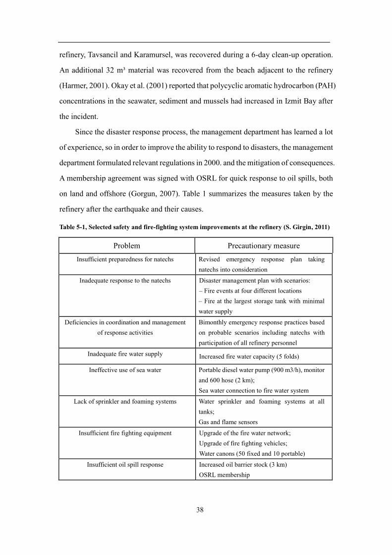
on land and offshore (Gorgun, 2007). Table 1 summarizes the measures taken by the
refinery after the earthquake and their causes.
Table 5-1, Selected safety and fire-fighting system improvements at the refinery (S. Girgin, 2011)
Problem Precautionary measure
Insufficient preparedness for natechs Revised emergency response plan taking
natechs into consideration
Inadequate response to the natechs Disaster management plan with scenarios: – Fire events at four different locations – Fire at the largest storage tank with minimal
water supply
Deficiencies in coordination and management
of response activities Bimonthly emergency response practices based
on probable scenarios including natechs with
participation of all refinery personnel
Inadequate fire water supply Increased fire water capacity (5 folds)
Ineffective use of sea water Portable diesel water pump (900 m3/h), monitor
and 600 hose (2 km); Sea water connection to fire water system
Lack of sprinkler and foaming systems Water sprinkler and foaming systems at all
tanks; Gas and flame sensors
Insufficient fire fighting equipment Upgrade of the fire water network; Upgrade of fire fighting vehicles; Water canons (50 fixed and 10 portable)
Insufficient oil spill response Increased oil barrier stock (3 km) OSRL membership

39
Moreover, the company reconstructed and reinforced the damaged building
structure in the earthquake. These measures not only consume a lot of resources, but
also affect the operation of the refinery. The majority of the units, which were out of
service due to the earthquake and fire damage, were put into operation within 3 months
after the earthquake when the refinery became functional again. The refinery's total
cost of repairing damaged buildings, equipment, and the environment was $57.8
million, about half of the initial estimate of $115 million. But the refinery was out of
service for a year. 95% of this loss was covered by the insurance (Danis and Gorgun,
2005). The operational loss of the refinery can be seen in Figure 5-5, which shows the
amount of crude-oil processed by TUPRAS refineries between 1996-2003. The
refinery’s loss of production due to the earthquake is evident from the sharp decrease
in the processing, while the other refineries have a steady trend (TUPRAS company
operates 4 refineries in Izmit, Izmir, Kirikkale and Batman). The loss is roughly
equivalent to 6 months (Hurriyet, 1999) of production loss.
Figure 5-5, Yearly distribution of crude-oil processed by Tupras refinery (Girgin 2011)
40
5.3.3 Social and Economic Impact
From the events of the refinery, we found that earthquake is a natech event and
the starting point of a disaster chain. Not only will the earthquake itself cause various
disasters, but also various secondary disasters, such as sand liquefaction, fires and
reservoir breaks. Among them, environmental disasters caused by earthquakes are
very important, but they are often overlooked. Earthquake secondary disasters at the
social level, such as road damage caused by traffic smashes, fires caused by gas
pipeline rupture, pollution of drinking water sources due to damage to sewers,
communication disruption caused by destruction of telecommunications facilities,
plague epidemics, factory toxic gas pollution, hospital bacterial contamination or
radioactive pollution. Historical experience shows that the casualties and losses caused
by secondary disasters are sometimes greater than direct disasters. Moreover, the
treatment after the earthquake is complicated and lengthy. Therefore, the impact of
earthquake disasters on the community should be highly valued.
In addition, when the earthquake occurs, we must not only consider a single
building, we need to form a complete urban system, which is the construction of urban
seismic recovery. The purpose of urban seismic resilience construction is to enable
cities to face the impact of different levels of earthquake disasters, and finally form a
disaster prevention system with multiple lines of defense to ensure that the main
functions of the city after the disaster are effective enough to minimize the loss of life,
property and economy. At present, the theory and practice of building earthquake-
resistant recover ability in cities is still in the exploratory stage, and long-term research
and summary are needed. The keyword “Resiliency” has been used by many
researchers in the context of earthquake engineering and in many ways (e.g., Bruneau
et al., 2003; Bruneau and Reinhorn, 2007; Cimellaro et al., 2009, and references
therein). The earthquake-resistant and disaster-resistant resilience is also an important
part of the construction of resilient cities.
41
6. Conclusion
The work done of this thesis is inserted within a research activity
interdisciplinary which figures out the refinery’s potential risks, among possible
external events, attention has been paid to the seismic event. The aim of this study is
based on the “potential dangers of petrochemical plants affected by seismic activity”,
according to the damage caused by the Kocaeli earthquake to the Tupras Izmit
petrochemical plant, the potential risk factors existing inside the petrochemical plant
are summarized.
In the refinery, components own intrinsic hazard due to the fact that very often
contain hazardous materials. Structural and seismic design analysis of the damaged
components are necessary for improve earthquake resistance. The advanced real-time
monitoring technology makes the emergency response more timely, and can greatly
control the damage within the resilience recovery capability of the community. In
additional to the dangers of specific structures, the potential hazards include post-
earthquake environment and economical loss due to equipment recovery and operation.
As we can seen from earthquake events history, the post-disaster environment is a
primarily problem for system recovery.
The risk factors discussed in view of Izmit refinery can be used as a reference for
other refineries. Industrial plants located in different regions can improve the facilities
structural design and seismic design based on their own condition, thus achieving the
mitigation of caused damages.
In additional, as the refinery damage did not cause casualties, the post-earthquake
community response did not allow any analysis of the people actively. But if we
consider in a larger community range, in realistic, the social stability after the
earthquake is very prominent, people lost their family, are homeless to live in temporary
tents; lifeline systems are struck, people’s emotion will be easily out of control,
resulting in social community problem. So citizens response can also be considered as
another potential risk factor.
42
7. Reference
Anne K., Keith O., Richard N., and Bahram S., ( January 1985) Seismic Risk to Major
Industrial Facilities
API Standard 653, Tank Inspection, Repair, Alteration, and Reconstruction, second
edition. 1995. Washington
AKSA: Annual report 2008, Istanbul, Turkey, 100 pp., 2009
Ayman M. Atta, Electric Desalting and Dewatering of Crude Oil Emulsion Based on
Schiff Base Polymers as Demulsifier. Sci. 8 (2013) 9474 - 9498
Danis, H. and Gorgun, M., Marmara earthquake and TUPRAS fire, in Proceedings of
Earthquake Symposium Kocaeli 2005, Kocaeli, Turkey, 23–25 March 2005,
1362–1369, 2005
Gary, James H., Handwerk, Glenn E., and Kaiser, Mark J.; Petroleum Refining
Technology and Economics; Fifth Edition; CRC Press; 2007
Girgin, S. (2011). The natech events during the 17 August 1999 Kocaeli earthquake:
Aftermath and lessons learned
Gorgun, M., Major industrial accidents happened in Korfez, Occupational Health and
Safety Congress, Adana, Turkey, 20–21 April 2007
Gulen, L., A. Pinar, D. Kalafat, N. Ozel, G. Horasan, M. Yilmazer, and A. M. Isıkara
(2002). Surface fault breaks, aftershock distribution, and rupture process of the
17 August 1999, Izmit, Turkey, earthquake, Bull. Seism. Soc. Am.92, no. 1, 230–
244
Harmer, T., Turkey-oil spill response following an earthquake, in: Proceedings of
International Oil Spill Conference 2001, Florida, USA, 26–29 March 2001, 457–
460, 2001
Hurriyet: TUPRAS set on fire by the stack, 24 August 1999
James G, Speight (2006). The Chemistry and Technology of Petroleum (Fourth ed.).
CRC Press. 0-8493-9067-2

43
Johnson, G., Aschheim, M., and Sezen, H., Industrial facilities, Earthq. Spectra, 16,
311–350, 2000
Kilic A. S., and Sozen M. A. 2003. Evaluation of Effect of August 17, 1999, Marmara
Earthquake on Two Tall Reinforced Concrete Chimneys. ACI Structural Journal.
Vol.100, No. 3, May-June 2003. pp. 357-364
Kiremidjian, AS and Ortiz, K and Nielson, R and Safavi, B. (2013). Seismic Risk to
Major Industrial Facilities
Kohei Suzuki (2000). Report on Damage of Industrial Facilities in the 1999 Kocaeli
Earthquake, Turkey
Masayoshi N and Oren L, Nakashima, M., Lavan, O., Kurata, M. et al. Earthq. Eng.
Eng. Vib. (2014) 13(Suppl 1): 141
Magnetrol, (2018) Petroleum refining brochure. Retrieved November 20,2018, from:
https://www.magnetrol.com/en/industries-applications/petroleum-refining
Mohamed. A, Ghorab (2016). Design and Study of Floating Roofs for Oil Storage
Tanks
Mohsen R. & Guy M., (2000). Performance of industrial facilities in the august
17,1999 Izmit earthquake
M.T. Tham and R.C. Costello, (2018) Basic distillation equipment and operation.
Retrieved 2018, from http://www.rccostello.com/distil/distileqp.htm
Okay, O. S., Tolun, L., Telli-Karakoc¸, F., Tufekci, V., Tufekci, H., and Morkoc, E.,
Izmit Bay (Turkey) ecosystem after Marmara Earthquake and subsequent
refinery fire: the long-term data, Mar. Pollut. Bull., 42, 361–369, 2001
Paolacci, F., et al. (2012). Analysis of the Seismic Risk of Major-Hazard Industrial
plants and applicability of Innovative Seismic Protection Systems
Petroleum Refining, by J. H. Gary, G. E. Handwerk, M. J. Kaiser, 5th Edition, CRC
press NY, 2007, Chapter 12, Product Blending, p.267
Planete energies (2015). The Three Stages of Refining. Retrieved November 20,2018
from https://www.planete-energies.com/en/medias/close/three-stages-refining
44
Sezen, H. and A. Whittaker (2006). Seismic Performance of Industrial Facilities
Affected by the 1999 Turkey Earthquake
Scott W. Golden, (2005), Crude unit preflash drums and colums.inc Texas,USA
Tokyo Gas Site. (2018). Retrieved November 15, 2018, from https://www.tokyo-
gas.co.jp/techno/english/category4/17_index_detail.Html
TUPRAS: Annual Report 2009, Istanbul, Turkey, 175 pp., 2010
Uniform Building Code, UBC Volume 2: Structural Engineering Design Provisions.
1997. International Conference of Building Officials. Whittier, California
United States Geological Survey (USGS), “Glossary of Terms on Earthquake
Maps”. Archived from the original on 2009-02-27. Retrieved 2018
United States Geological Survey (USGS). "Earthquake Facts and Statistics". November
29, 2012. Archived from the original on 2010-05-24. Retrieved 2018
Wikipedia, (2018) Alkylation unit. Retrieved November 19,2018, from
https://en.wikipedia.org/wiki/Alkylation_unit