potential of process energy optimization (peo)™ on a soda
TRANSCRIPT

54 Energy Engineering Vol. 107, No. 4 2010
Potential of Process EnergyOptimization (PEO)™ on aSoda Ash Production Plant
T. de Lange and Prof. L.J. GroblerEnergy Cybernetics
Potchefstroom, South Africa
ABSTRACT
An energy audit was conducted on a soda ash plant in Botswana, and it was found that the performance of the plant could be improved. Further investigation revealed that the performance of the carbon diox-ide (CO2) production section was heavily influenced by control problems experienced at the two coal-firing boilers. The CO2 production section consumes energy in the form of steam and electricity and utilizes a sol-vent mono-ethanol-amine (MEA) to extract CO2 from boiler flue gasses. Recommendations were made to repair and re-commission the boiler control system and to install an energy optimization system. An-nual savings that could be achieved by optimal control of steam from the boilers to the turbine, CO2 plant, and processing plant (thereby control-ling the interactions between these sections) amounted to BWP 2, 6 mil-lion. This constitutes 10% of the total annual coal bill. A total project life cycle of only 5 years was used, and the escalat-ing savings due to inflation was disregarded. The IRR of the project was calculated to be 114%. This article covers the results of the energy audit. It also discusses the proposed solution and the savings potential that was identified re-garding the CO2 plant.
INTRODUCTION
Soda ash is a chemical used in the manufacturing of glass and detergents. It is also used in metallurgical applications and chemical

55
manufacturing. The soda ash plant consists of a few processes or sec-tions. This article will only focus on the process and operation of the CO2 production section.
Description of the CO2 Production Process CO2 in flue gas from the two coal-fired boilers is extracted to be used in the carbonation of Sodium Carbonate (Na2CO3). In this exother-mic chemical reaction Sodium Bicarbonate (2NaHCO3) is formed. Figure 1 shows a block diagram of the CO2 plant. Flue gas from the boilers is scrubbed, using a soda ash-rich brine solution to remove the sulphur dioxide (SO2) from the gas. SO2 is removed from flue gas since it reacts with and contaminates the MEA solution used in the subsequent purification process. The scrubbed flue gas is then passed through a packed CO2 absorp-tion column, where it contacts the MEA solution. In Heat Exchanger 1 (HE1) the CO2-rich MEA solution is preheated before it is pumped to the top of the CO2 stripping column. CO2 is stripped by boiling the solution, using low pressure (LP) steam in the two kettle-type re-boilers. Gaseous CO2 is compressed and pumped to the carbonation section. The main energy consumers of this section are the re-boilers that use LP steam to heat the MEA. Some electrical energy is used for pump-ing and various other purposes; however, this article focuses on the steam consumption of this section.
Purpose of the Audit The purpose of the energy management (EM) and Process Energy Optimization™ (PEO™) study was to maximize production while minimiz-ing production costs and resources. This had to be accomplished without violating process or equipment constraints. The audit revealed that plant performance could be improved and that the CO2 production section was consuming large amounts of energy.
CO2 PRODUCTION SECTION PERFORMANCE AND OPERATION
The first step in the evaluation of the CO2 production section was the analysis of this section’s performance over a period of three months.

56 Energy Engineering Vol. 107, No. 4 2010
Figu
re 1
. Blo
ck d
iagr
am o
f C
O2
prod
uctio
n se
ctio
n

57
CO2 Production Section Performance The performance of the CO2 production section can be seen in Fig-ure 2. Steam energy consumed at the re-boilers is shown as a function of CO2 production. The trend line in Figure 2 indicates the average performance of the CO2 plant. As expected, the CO2 production increases with an increase in energy consumption. There is, however, a large scatter around the aver-age performance line. The base load is high, indicating that, although no CO2 is produced, the system consumes a lot of energy. It can therefore be concluded that process or energy improvement is possible. In Figure 2, Point A indicates that on one day 3,400 GJ of steam was used to produce 56,550 m3 of CO2. On another day only 2,350 GJ of steam energy was consumed (see Point B) to produce approximately the same amount of CO2. This constitutes a 30% difference in steam consumption for production of the same amount of CO2. Possible causes of the large scatter or variance in performance as well as the large base load were explored. From this it was found that the energy consumed by the CO2 production section was a function of the following [1]:
• The amount of flue gas used to produce CO2 and the percentage CO2 it contained
• Percentage MEA in solution• The rate at which the MEA solution was pumped through the CO2
production section• Heat exchanged at the re-boilers, depending on the amount of
steam to the re-boilers
Current Operation Methodology Some difficulty was experienced in controlling the coal-fired boilers and cutting back on steam production when the soda ash plant was not at full production. According to plant personnel, the CO2 re-boilers were used as a heat sink at times when too much steam was produced. It was thought that the excess heat “dumped” at the re-boilers would ultimately be dissipated through the two heat exchangers (HE 1 and HE 2 in Figure 1). The excess heat would eventually heat up brine that was pumped back to the ponds, thereby improving evaporation rates. In addition to heat being dumped at the CO2 re-boilers, another

58 Energy Engineering Vol. 107, No. 4 2010
Figu
re 2
. CO
2 pr
oduc
tion
sect
ion
perf
orm
ance
59
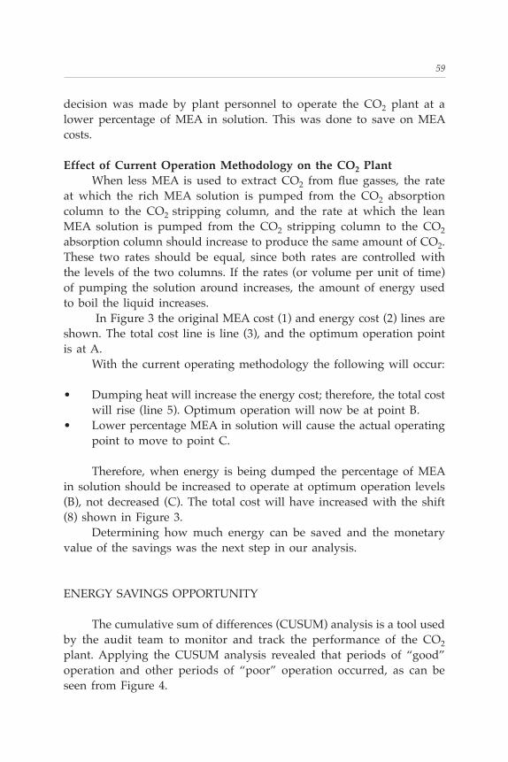
decision was made by plant personnel to operate the CO2 plant at a lower percentage of MEA in solution. This was done to save on MEA costs.
Effect of Current Operation Methodology on the CO2 Plant When less MEA is used to extract CO2 from flue gasses, the rate at which the rich MEA solution is pumped from the CO2 absorption column to the CO2 stripping column, and the rate at which the lean MEA solution is pumped from the CO2 stripping column to the CO2 absorption column should increase to produce the same amount of CO2. These two rates should be equal, since both rates are controlled with the levels of the two columns. If the rates (or volume per unit of time) of pumping the solution around increases, the amount of energy used to boil the liquid increases. In Figure 3 the original MEA cost (1) and energy cost (2) lines are shown. The total cost line is line (3), and the optimum operation point is at A. With the current operating methodology the following will occur:
• Dumping heat will increase the energy cost; therefore, the total cost will rise (line 5). Optimum operation will now be at point B.
• Lower percentage MEA in solution will cause the actual operating point to move to point C.
Therefore, when energy is being dumped the percentage of MEA in solution should be increased to operate at optimum operation levels (B), not decreased (C). The total cost will have increased with the shift (8) shown in Figure 3. Determining how much energy can be saved and the monetary value of the savings was the next step in our analysis.
ENERGY SAVINGS OPPORTUNITY
The cumulative sum of differences (CUSUM) analysis is a tool used by the audit team to monitor and track the performance of the CO2 plant. Applying the CUSUM analysis revealed that periods of “good” operation and other periods of “poor” operation occurred, as can be seen from Figure 4.

60 Energy Engineering Vol. 107, No. 4 2010
Figu
re 3
. MEA
and
Ene
rgy
cost
vs.
per
cent
age
MEA
in
solu
tion

61
The dashed line in Figure 4 indicates periods of “poor” operation while the dotted line represents periods of “good” operation. The solid line is a period of “average” operation. Figure 4 shows a long period of “poor” operation, after which something changed and the operation improved for a few days. Op-eration alternated between modes of “good,” “average,” and “poor” throughout the measured period. Energy could have been saved if the plant were primarily operated in a mode of “good” operation, as had already happened some of the time. The amount of energy that could have been saved was calculated by subtracting the performance line during the “good” performance pe-riods from the performance line during all periods. The savings resulting from changing “average” operation to “good” operation can be seen in Figure 5. Average performance of the CO2 production section during all modes of operation is shown in the solid line. Figure 5 also shows the performance line during the “good” operation periods in the dotted line. Steam could be saved if the plant were operated at good operation levels most of the time. Savings were calculated in terms of the coal required to generate that amount of steam. Table 1 shows the coal bill for the calculated base year (BWP 25,734,143). The annual savings calculated on this base year coal cost was BWP 2,560,795. If a total project life cycle of only 5 years is used and escalating savings due to inflation is disregarded (a very conservative view), the IRR of the project is calculated to be 114% with a payback period of 1.15 years. Apart from these savings, dumping energy at the re-boilers affects the production process in various ways. These effects will be discussed in detail in the next section.
EFFECTS OF DUMPING ENERGY AT THE REBOILERS
Dumping of excess steam at the re-boilers directly affects the opera-tion/performance of the CO2 plant in the following manner:
• Temperature T1 (shown in Figure 1) will increase if not all of the

62 Energy Engineering Vol. 107, No. 4 2010
Figu
re 4
. CU
SUM
Cha
rt o
f C
O2
prod
uctio
n se
ctio
n

63
Figu
re 5
. CO
2 Pr
oduc
tion
vs. S
team
Ene
rgy

64 Energy Engineering Vol. 107, No. 4 2010
Table 1. Estimated value of savings opportunity
excess heat is dissipated through HE 1&2. This in turn will cause less CO2 to be absorbed at the CO2 absorption column and a drop in relative yield of CO2. Therefore, it indirectly affects the down-stream carbonation process.
• The temperature in the CO2 stripping column will increase and a larger volume of gas will be boiled off, containing impurities. These impurities will be compressed along with the CO2 and pumped to the carbonation section.
The first step in solving these problems is the repair and re-com-missioning of the boiler control system. This will enable plant operators to cut back on steam production when the need arises. Process Energy Optimization (PEO™) will enable operators to improve the operational efficiency of the CO2 production section. The PEO™ solution can be deployed by installing a decision support system (DSS). The effect of a DSS on the performance scatter shown in Figure 2 will be to narrow the scatter around the average performance line. It will also enable operators to shift the performance from average performance to good operation levels.
THE DECISION SUPPORT SYSTEM (DSS)
In essence the DSS will firstly aim to assist the operators of the plant in anticipating the steam demand of the plant. This demand should be met in the most cost effective manner. The DSS will structure the demand as follows:
• Steam demand to the calcining section will be prioritized.

65
• Secondary to the steam supply to the calcining section will be that of the turbine for generation purposes, and the supply to the MEA re-boilers for CO2 production purposes.
• The remaining amount of steam will be made available to other steam users such as the MEA re-claimer and salt production sec-tion.
As far as possible the existing infrastructure (i.e. sensors and equip-ment) will be used and the introduction of new equipment (if any) kept minimal. Some production-related problems and bottlenecks can be elimi-nated by the energy performance measurements and tracking system. This information must be made available to operators in real time to facilitate their meeting production targets. The system will function as a DSS; thus, human intervention will not be excluded from the control loop. This strategy will eliminate risk, and once the performance of the system has been verified the option to close the control loop can be considered.
CONCLUSION
The Energy Audit conducted on the soda ash plant showed that the performance of the CO2 plant could be improved. Dumping energy as a result of limited boiler control had an adverse effect on the production process. It can be concluded that these problems are symptoms of control problems experienced at the boilers. Therefore, an integrated solution was proposed. The PEO™ solution aims to optimize and maintain the boilers, as well as the production section, at optimum levels. Annual energy savings for the whole project was calculated to be BWP 2, 6 million. This investment could be reclaimed in 1.15 years.
References[1] Grobler, Prof. L.J., Bosman, I.E., Molefhi, B., De Lange, T. & Kaliswayo, L., Ener-
gy Audit Report, 2006.
——————————————————————————————

66 Energy Engineering Vol. 107, No. 4 2010
ABOUT THE AUTHORS Tanya de Lange holds a degree in chemical engineering from the North-West University, South Africa. She is an employee of the North-West University and Energy Cybernetics, where she focuses on the energy engineering field. She is a member of the Southern African Asso-ciation for Energy Efficiency (SAEE). Tanya is a certified energy manager (CEM) as well as a certified measurement and verification professional (CMVP).
L.J. Grobler is a professor at the School of Mechanical Engineering, North-West University, South Africa. He specializes in energy manage-ment and process energy optimization. He is certified by the Association of Energy Engineers of the USA as a certified energy manager (CEM) and as a certified measurement and verification professional (CMVP).
Both can be reached at Energy Cybernetics, PostNet Suite 148, Private Bag X1277, Potchefstroom, 2520, South Africa.

Applicable Discount
Georgia Residentsadd 6% Sales Tax
Shipping Fees
TOTAL
Indicate shipping address:
NAME (Please print) BUSINESS PHONE
SIGNATURE (Required to process order) EMAIL ADDRESS
COMPANY
STREET ADDRESS ONLY (No P.O. Box)
CITY, STATE, ZIP
MEMBER DISCOUNTSA 15% discount is allowed to AEE members.
AEE Member (Member No._____________________)
Make check payablein U.S. funds to:
AEE ENERGY BOOKS
CODE: Journal 2010
10.00
TO ORDER BY PHONEUse your credit card and call:
(770) 925-9558
TO ORDER BY FAXComplete and Fax to:
(770) 381-9865
INTERNATIONAL ORDERSMust be prepaid in U.S. dollars and must include an additional charge of $10.00 per book plus 15% for shipping and handling by surface mail.
INTERNET ORDERINGwww.aeecenter.org
Send your order to:AEE BOOKS P.O. Box 1026Lilburn, GA 30048
Quantity Book Title Order Code Price Amount Due
Complete quantity and amount due for each book you wish to order:
THE SMART GRID: Enabling Energy Efficiency and Demand Response 0630 $125.00
BOOK ORDER FORM
Select method of payment:CHECK ENCLOSEDCHARGE TO MY CREDIT CARD
VISA MASTERCARD AMERICAN EXPRESS
CARD NO.
Expiration date Signature
④
①
②
③
"
ORDER CODE: 0630
———CONTENTS———
THE SMART GRID: Enabling Energy Efficiency and Demand Response Clark GellingsThe power system has often been cited as the greatest and most complex machine ever built, yet it is predominantly a mechanical system. How-ever, technologies and intelligent systems are now available which can significantly enhance the overall functionality of power distribution, and make it ready to meet the needs the 21st century. This book explains in detail how sensors, communications technologies, computational ability, control, and feedback mechanisms can be effectively combined to create this new, continually adjusting “smart grid” system. You’ll gain an un-derstanding of both IntelliGridSM architecture and EnergyPortSM, as well as how the integration of intelligent systems can be effectively utilized to-ward achieving the goals of reliability, cost containment, energy efficiency in power production and delivery, and end-use energy efficiency.
6 x 9, 301 pp., Illus.Hardcover, $125
1 – What is the Smart Grid? 2 – Electric Energy Efficiency in Power Production & Delivery 3 – Electric End-Use Energy Efficiency 4 – Using a Smart Grid to Evolve the Perfect Power System 5 – DC Distribution & the Smart Grid 6 – The IntelliGridSM Architecture for the Smart Grid 7 – The Smart Grid – Enabling Demand Response: The Dynamic Energy Systems Concept 8 – The EnergyPortSM as Part of the Smart Grid 9 – Policies & Programs to Encourage End-Use Energy Efficiency 10 – Market Implementation 11 – Efficient Electric End-Use Technology Alternatives 12 – Demand-Side Planning 13 – Demand-Side EvaluationAppendix, Index
ISBN: 0-88173-623-6

Applicable Discount
Georgia Residentsadd 6% Sales Tax
Shipping Fees
TOTAL
Indicate shipping address:
NAME (Please print) BUSINESS PHONE
SIGNATURE (Required to process order) EMAIL ADDRESS
COMPANY
STREET ADDRESS ONLY (No P.O. Box)
CITY, STATE, ZIP
MEMBER DISCOUNTSA 15% discount is allowed to AEE members.
AEE Member (Member No._____________________)
Make check payablein U.S. funds to:
AEE ENERGY BOOKS
CODE: Journal 2010
10.00
TO ORDER BY PHONEUse your credit card and call:
(770) 925-9558
TO ORDER BY FAXComplete and Fax to:
(770) 381-9865
INTERNATIONAL ORDERSMust be prepaid in U.S. dollars and must include an additional charge of $10.00 per book plus 15% for shipping and handling by surface mail.
INTERNET ORDERINGwww.aeecenter.org
Send your order to:AEE BOOKS P.O. Box 1026Lilburn, GA 30048
Quantity Book Title Order Code Price Amount Due
Complete quantity and amount due for each book you wish to order:
Energy Management Reference Library CD 0636 $450.00
BOOK ORDER FORM
Select method of payment:CHECK ENCLOSEDCHARGE TO MY CREDIT CARD
VISA MASTERCARD AMERICAN EXPRESS
CARD NO.
Expiration date Signature
④
①
②
③
"
ORDER CODE: 0636
FOUR COMPLETE BOOKS ON ONE CD-ROM…Including over 2100 pages of text, graphics, charts and illustrations, the Energy Management Reference Library CD provides an economical training, research and reference resource for today’s energy professional. Indexed with bookmarks for convenient navigation, the CD-ROM contains the following four complete books in Adobe PDF® format:Energy Management Handbook, 7th EditionBy Wayne C. Turaner and Steve DotyThis comprehensive 800+ page handbook has become recognized as the definitive stand-alone energy manager's desk reference, used by thousands of energy management professionals throughout industry.
Guide to Energy Management, 6th EditionBy Barney Capehart, Wayne Turner, and William KennedyThis best selling book provides a manager's guide to the most important areas of energy cost cutting. Written by three of the most respected energy professionals in the industry, it examines the fundamental objectives of energy management, and illustrates tools and techniques proven effective for achieving results.
Solutions Manual for Guide to Energy Management, 6th EditionBy Klaus-Dieter E. PawlikThis practical study guide serves as a valuable companion text, providing worked out solutions to all of the problems presented in Guide to Energy Management Fifth Edition.
Handbook of Energy Engineering, 6th EditionBy Albert Thumann and D. Paul MehtaThis reference will guide you step by step in applying the principles of energy engineering and management to the design of electrical, HVAC, utility, process and building systems for both new design and retrofit projects.