poterton suprima installation guide
DESCRIPTION
Poterton SuprimaTRANSCRIPT
See inside cover for models covered by these instructions For use with boiler code B (or higher) models only
Installation & Service Instructions
Suprima 30 - 80
Wall Mounted Fan Assisted Balanced Flue Gas Boilers
THE GAS SAFETY (INSTALLATION AND USE) REGULATIONS 1998.
‘‘ In your own interest, and that of safety, it is law that all gas appliances are installed by competent persons, in accordance with the above regulations. Failure to install appliances correctly could lead to prosecution.’’
Installation must be in accordance with the Installation & Service Instructions and the rules in force.
Leave these Instructions and the Benchmark Log Book with the User for use on future calls
For Use With Natural Gas (G20) Only At 20mbar For Use in GB & IE
IMPORTANT
PLEASE READ THIS BOOK BEFORE INSTALLING, OPERATING OR SERVICING THIS BOILER.
Page 1 of 53
23/10/2010http://www.partsarena.co.uk/baxi/System/DATA/Dx/DS1/installation/2221/I04-2221/...
page 1
Contents
Technical Data 3 Introduction 4 1. Installation Requirements 4 1.1 Health & Safety Information 4 1.2 Codes of Practice 4 1.3 Gas Supply 5 1.4 Electricity Supply 5 1.5 Location of Boiler 5 1.6 Air Supply 7 1.7 Flue Systems 7 1.8 Flue Terminal Location 8 1.9 The System 8 Flue Kits 12 System and Other Kits 14 2. Installation 16 2.1 Unpack & Prepare the Boiler 16 2.2 Install the Flue 16 2.3 Connect the Power Supply
Cable 18
2.4 Install the Optional Programmer 19 2.5 Connect the Gas Supply 19 2.6 Connect the Water Supply 20 3. Commissioning 21 3.1 Commission the Boiler 22 3.2 Final Adjustments 23 3.3 Instruct the User 23 3.4 Advise the User 23 4. To Service the Boiler & Component
Replacement 24
4.1 General Access 24 4.2 To Service the Boiler 25 4.3 Component Replacement 25 4.3.1 Electronic Control Board 26 4.3.2 Air Pressure Switch 25 4.3.3 Electrode 26 4.3.4 Burner 27 4.3.5 Injector 27 4.3.6 Combustion Chamber
Insulation 27
4.3.7 Gas Valve 28 4.3.8 Fan & Flue Hood 29 4.3.9 Temperature Sensor 30 4.3.10 Overheat Thermostat 30 4.3.11 Heat Exchanger 31 5. Functional Wiring Diagram 32 6. Wiring Diagrams 33 7. Fault Finding 34
Page 2 of 53
23/10/2010http://www.partsarena.co.uk/baxi/System/DATA/Dx/DS1/installation/2221/I04-2221/...
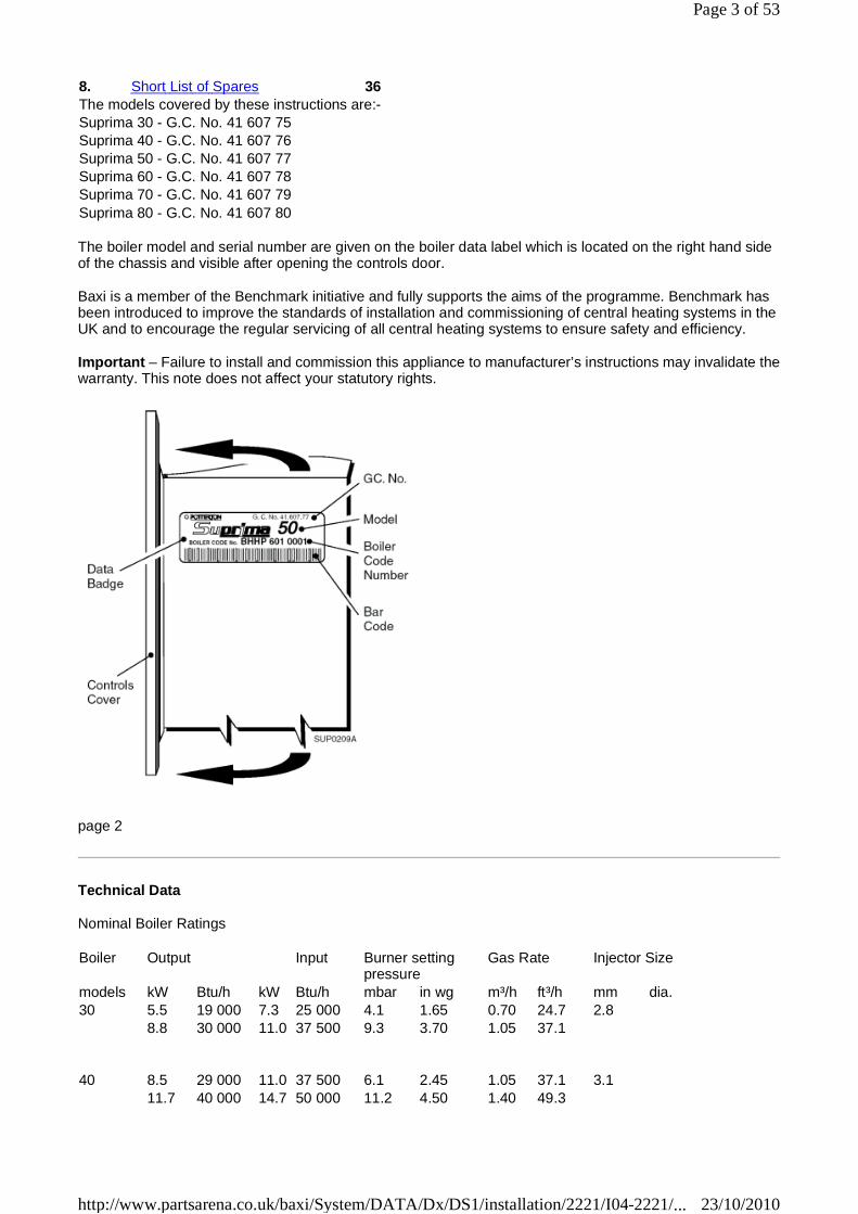
The boiler model and serial number are given on the boiler data label which is located on the right hand side of the chassis and visible after opening the controls door.
Baxi is a member of the Benchmark initiative and fully supports the aims of the programme. Benchmark has been introduced to improve the standards of installation and commissioning of central heating systems in the UK and to encourage the regular servicing of all central heating systems to ensure safety and efficiency.
Important – Failure to install and commission this appliance to manufacturer’s instructions may invalidate thewarranty. This note does not affect your statutory rights.
page 2
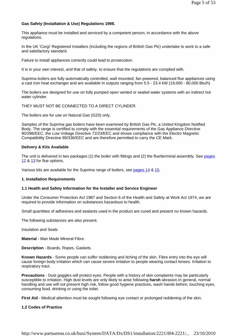
Technical Data
Nominal Boiler Ratings
8. Short List of Spares 36 The models covered by these instructions are:- Suprima 30 - G.C. No. 41 607 75 Suprima 40 - G.C. No. 41 607 76 Suprima 50 - G.C. No. 41 607 77 Suprima 60 - G.C. No. 41 607 78 Suprima 70 - G.C. No. 41 607 79 Suprima 80 - G.C. No. 41 607 80
Boiler Output Input Burner setting pressure
Gas Rate Injector Size
models kW Btu/h kW Btu/h mbar in wg m³/h ft³/h mm dia. 30 5.5 19 000 7.3 25 000 4.1 1.65 0.70 24.7 2.8
8.8 30 000 11.0 37 500 9.3 3.70 1.05 37.1
40 8.5 29 000 11.0 37 500 6.1 2.45 1.05 37.1 3.1 11.7 40 000 14.7 50 000 11.2 4.50 1.40 49.3
Page 3 of 53
23/10/2010http://www.partsarena.co.uk/baxi/System/DATA/Dx/DS1/installation/2221/I04-2221/...

page 3
Introduction
50 11.4 39 000 14.8 50 500 6.7 2.65 1.42 50.1 3.5 14.7 50 000 18.3 62 500 10.3 4.10 1.75 61.8
60 14.4 49 000 18.6 63 500 8.6 3.45 1.78 62.9 3.7 17.6 60 000 22.0 75 000 12.2 4.90 2.10 74.2
70 17.3 59 000 22.0 75 000 9.6 3.85 2.10 74.2 3.9 20.5 70 000 25.6 87 500 13.4 5.35 2.45 86.4
80 20.1 68 500 25.6 87 500 10.7 4.28 2.45 86.4 4.1 23.4 80 000 29.3 100 000 13.9 5.56 2.80 98.7
Maximum Working Head
Minimum Working Head
30.5 m (100 ft)
150 mm (6 in) Gas Supply Pressure
Gas Supply Connection
20 mbar
Rc. ½ (½ in BSP Female) Maximum Flow Temperature
Flow/Return Connections
Water Content
82°C
22 mm Copper
1.7 litres (0.37 gal) - 30, 40, 50 & 60 Models
2.1 litres (0.46 gal) - 70 & 80 Model Appliance Lift Weight 26.0 kg (57.3 lbs) - 30, 40, 50 & 60 Models
30.2 kg (66.6 lbs) - 70 & 80 Model Appliance Weight Installed - Dry
32.0 kg (70.0 lbs) - 30, 40, 50 & 60 Models
35.4 kg (78.1 lbs) - 70 & 80 Model Electricity Supply
Internal Fuse
Power Consumption
230v ~ 50Hz Fused at 3A
Type 3.15AT
80 Watts (excluding pump) Classifications CAT 1 2 H
C12, C32 & C71 (C71 30 - 60 models only)
IP20
Page 4 of 53
23/10/2010http://www.partsarena.co.uk/baxi/System/DATA/Dx/DS1/installation/2221/I04-2221/...
Gas Safety (Installation & Use) Regulations 1998.
This appliance must be installed and serviced by a competent person, in accordance with the above regulations.
In the UK 'Corgi' Registered Installers (including the regions of British Gas Plc) undertake to work to a safe and satisfactory standard.
Failure to install appliances correctly could lead to prosecution.
It is in your own interest, and that of safety, to ensure that the regulations are complied with.
Suprima boilers are fully automatically controlled, wall mounted, fan powered, balanced flue appliances using a cast iron heat exchanger and are available in outputs ranging from 5.5 - 23.4 kW (19,000 - 80,000 Btu/h)
The boilers are designed for use on fully pumped open vented or sealed water systems with an indirect hot water cylinder.
THEY MUST NOT BE CONNECTED TO A DIRECT CYLINDER.
The boilers are for use on Natural Gas (G20) only.
Samples of the Suprima gas boilers have been examined by British Gas Plc, a United Kingdom Notified Body. The range is certified to comply with the essential requirements of the Gas Appliance Directive 90/396/EEC, the Low Voltage Directive 72/23/EEC and shows compliance with the Electro Magnetic Compatibility Directive 89/336/EEC and are therefore permitted to carry the CE Mark.
Delivery & Kits Available
The unit is delivered in two packages (1) the boiler with fittings and (2) the flue/terminal assembly. See pages 12 & 13 for flue options.
Various kits are available for the Suprima range of boilers, see pages 14 & 15.
1. Installation Requirements
1.1 Health and Safety Information for the Installer and Service Engineer
Under the Consumer Protection Act 1987 and Section 6 of the Health and Safety at Work Act 1974, we are required to provide information on substances hazardous to health.
Small quantities of adhesives and sealants used in the product are cured and present no known hazards.
The following substances are also present.
Insulation and Seals
Material - Man Made Mineral Fibre.
Description - Boards, Ropes, Gaskets.
Known Hazards - Some people can suffer reddening and itching of the skin. Fibre entry into the eye will cause foreign body irritation which can cause severe irritation to people wearing contact lenses. Irritation to respiratory tract.
Precautions - Dust goggles will protect eyes. People with a history of skin complaints may be particularly susceptible to irritation. High dust levels are only likely to arise following harsh abrasion.In general, normal handling and use will not present high risk, follow good hygiene practices, wash hands before, touching eyes, consuming food, drinking or using the toilet.
First Aid - Medical attention must be sought following eye contact or prolonged reddening of the skin.
1.2 Codes of Practice
Page 5 of 53
23/10/2010http://www.partsarena.co.uk/baxi/System/DATA/Dx/DS1/installation/2221/I04-2221/...
The boiler must be installed in accordance with: The Gas Safety (Installation and Use) Regulations 1998 and the current issue of:-
The Building Regulations, Building Standards (Scotland) Regulations, Local Building Regulations, Model and local Water Undertaking Bye-laws, IEE Wiring Regulations and Health & Safety Document No. 635 "The Electrician At Work Regulations 1989".
page 4
1.3 Gas Supply
The meter and supply pipes must be capable of delivering this quantity of gas in addition to the demand from any other appliances in the house and must be governed at the meter.
The complete installation must be tested for gas soundness and purged as described in BS6891.
1.4 Electricity Supply
230V ~ 50Hz via a fused double pole switch with a contact separation of at least 3 mm in both poles adjacent to the boiler. Power consumption is approximately 150W. There must be only one common isolator for the boiler and its control system and it must provide complete electrical isolation.
Fuse the supply at 3 A. The minimum requirement for the power supply cable is that it should be a PVC sheathed cord at least 0.75 mm² (24 x 0.2 mm) (code designation HO5 VV-F or HO5 VVH2-F) as specified in table 16 of BS6500:1984.
All wiring external to the boiler shall comply with the latest IEE Wiring Regulations, and any local regulations which apply.
WARNING: THIS APPLIANCE MUST BE EARTHED.
In the event of an electrical fault after installation of the boiler, preliminary electrical systems checks must be carried out i.e. Earth Continuity, Short Circuit, Polarity and Resistance to Earth.
1.5 Location of Boiler
The boiler is not suitable for external installation unless it is suitably protected.
If the sealed system kit (Part No. 238027) is being used, this should be installed first. See instructions supplied with kit.
The boiler must be installed so that the flue terminal is exposed to the external air. It is important that the position of the terminal allows the free passage of air across it at all times.
The boiler must be mounted on a flat wall which is sufficiently robust to take the weight of the boiler.
The boiler is suitable for installation to a combustible wall e.g. wood cladding, provided that the flue duct is not closer than 25 mm to combustible material. A metal sleeve should be installed to surround the flue duct toprovide a 25mm annular space. Further guidance is given in BS5440:1:1990, sub-clauses 3.3 and 4.2.5.
If the boiler is to be installed in a timber framed building it should be fitted in accordance with the British Gas publication-Part 19 - Building and Kitchen Work. If in doubt advice must be sought from Potterton Myson.
The boiler may be installed in any room, although particular attention is drawn to the requirements of the current IEE Wiring Regulations and, in Scotland, the electrical provisions of the Building Standards applicable in Scotland with respect to the installation of the boiler in a room containing a bath or shower.
Where a room-sealed appliance is installed in a room containing a bath or shower, any electrical switch or appliance control, utilising mains electricity should be so situated that it cannot be touched by a person using the bath or shower.
Where the installation of the boiler will be in an unusual position, special procedures may be necessary and
Page 6 of 53
23/10/2010http://www.partsarena.co.uk/baxi/System/DATA/Dx/DS1/installation/2221/I04-2221/...

BS6798 and BS5546 give detailed guidance on this aspect.
A cupboard or compartment used to enclose the boiler must be designed and constructed specifically for this purpose. An existing cupboard or compartment may be used provided that it is modified for the purpose. Details of essential features of cupboard/compartment design including airing cupboard installations are given in BS6798 and BS5546 and should be complied with.
The boiler requires only the clearances shown on Page 6, after installation.
page 5
Page 7 of 53
23/10/2010http://www.partsarena.co.uk/baxi/System/DATA/Dx/DS1/installation/2221/I04-2221/...
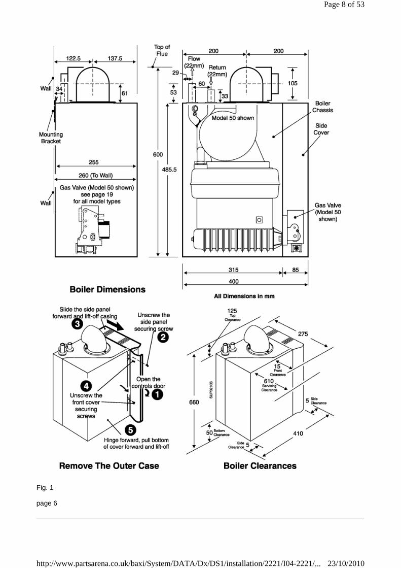
Fig. 1
page 6
Page 8 of 53
23/10/2010http://www.partsarena.co.uk/baxi/System/DATA/Dx/DS1/installation/2221/I04-2221/...

1.6 Air Supply
The air requirements must meet BS 5440 Part 2.
The room in which the boiler is installed does not require a purpose provided air vent.
1.6.1 Ventilated Cupboard/Compartment:
If the boiler is installed in a cupboard or compartment (with the exception of those installations covered by Section 1.6.2), permanent air vents are required in the cupboard or compartment, one at high level and one at low level, either direct to the outside air or to a room. Both high level and low level air vents must communicate with the same room or must be on the same wall to outside air. Both the high level and low level vent must each have a free area as stated below. The free area of each vent may be halved if the ventilation is provided directly from outside.
If the boiler is installed in a cupboard or compartment with a door, allow at least 15 mm clearance between the front of the boiler and the door for air movement.
1.6.2 Unventilated Compartment:
The 30, 40 and 50 models can be installed in an unventilated compartment providing the following conditions are met and no other heat sources are present within the compartment:
Maximum Horizontal flue length from turret: 560 mm
Minimum clearances for alternative configurations
1.7 Flue Systems
Horizontal
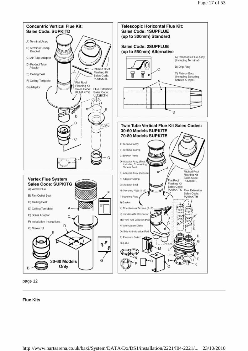
• The flue/terminal assembly supplied is suitable for a wall thickness of between 150 mm and 400 mm.
• A flue/terminal assembly suitable for a wall thickness of up to 600 mm is also available.
• Both the flue/terminal assemblies are telescopic and the minimum lengths (150 mm/6 in) are achieved by cutting.
• 1 m flue extensions are available.
• Under no circumstances should the total flue length exceed - 3.4 m, 30 - 70 models.
- 2.4 m, 80 models.
Vertical
1. Twin Tube system. 30 - 80 models.
Maximum actual length 7 m (7 extensions) Maximum equivalent resistance = 7 m
2. Vertical Concentric system.
30 - 70 models - Maximum actual length 3.4 m, equivalent resistance = 3.4 m. 80 models - Maximum actual length 2.4 m, equivalent resistance = 2.4 m.
Models: 30: 99 cm² 40: 133 cm² 50: 169 cm² 60: 198 cm² 70: 231 cm² 80: 264 cm²
Front 280 mm or Front 490 mm Side 75 mm Side 175 mm Bottom 250 mm Bottom 100 mm Top 450 mm Top 265 mm
Page 9 of 53
23/10/2010http://www.partsarena.co.uk/baxi/System/DATA/Dx/DS1/installation/2221/I04-2221/...

Vertex
• The maximum primary flue length is 3.4 m.
• The maximum secondary flue length is: 30 model 5 m 40 model 5.5 m 50 & 60 models 6 m
Note: The flue lengths quoted refer to straight lengths. For the effects of bends and offsets see Section 2.2 'Install the Flue' or the appropriate flue instructions.
page 7
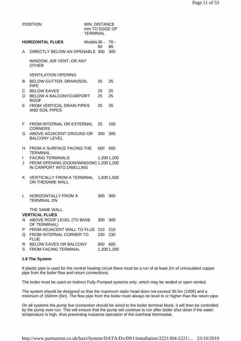
1.8 Flue Terminal Location
If a horizontal flue is sited less than 2m above a balcony, above ground, or above a flat roof to which people have access, a suitable terminal guard must be fitted. This serves two purposes, to protect the terminal against damage or interference and to protect passers-by. A terminal guard is available (Sales Code: PTERMGUARDEF).
Note: Where a flue terminal is installed less than 1 metre from a plastic, or painted gutter, or 500mm from painted eaves, an aluminium shield 1 metre long, should be fitted to the underside of the gutter or painted surface. A suitable wall plate should be fitted to the painted wall surface of a mobile home.
IMPORTANT: It is absolutely ESSENTIAL, to ensure that products of combustion discharging from the terminal cannot reenter the building, or any other adjacent building, through ventilators, windows, doors, natural air infiltration, or forced ventilation/air conditioning. If products of combustion are found to be re-entering any building, the appliance MUST be turned OFF IMMEDIATELY.
Fig. 2
Page 10 of 53
23/10/2010http://www.partsarena.co.uk/baxi/System/DATA/Dx/DS1/installation/2221/I04-2221/...
1.9 The System
If plastic pipe is used for the central heating circuit there must be a run of at least 2m of uninsulated copper pipe from the boiler flow and return connections.
The boiler must be used on Indirect Fully Pumped systems only, which may be sealed or open vented.
The system should be designed so that the maximum static head does not exceed 30.5m (100ft) and a minimum of 150mm (6in). The flow pipe from the boiler must always be level to or higher than the return pipe.
On all systems the pump live connection should be wired to the boiler terminal block, it will then be controlled by the pump over-run. This will ensure that the pump will continue to run after boiler shut down if the water temperature is high, thus preventing nuisance operation of the overheat thermostat.
POSITION MIN. DISTANCE mm TO EDGE OF TERMINAL
HORIZONTAL FLUES Models 30 - 60
70 - 80.
A DIRECTLY BELOW AN OPENABLE
WINDOW, AIR VENT, OR ANY OTHER
VENTILATION OPENING
300 300
B BELOW GUTTER, DRAIN/SOIL PIPE
25 25
C BELOW EAVES 25 25 D BELOW A BALCONY/CARPORT
ROOF 25 25
E FROM VERTICAL DRAIN PIPES AND SOIL PIPES
25 25
F FROM INTERNAL OR EXTERNAL CORNERS
25 100
G ABOVE ADJACENT GROUND OR BALCONY LEVEL
300 300
H FROM A SURFACE FACING THE TERMINAL
600 600
I FACING TERMINALS 1,200 1,200 J FROM OPENING (DOOR/WINDOW)
IN CARPORT INTO DWELLING 1,200 1,200
K VERTICALLY FROM A TERMINAL ON THESAME WALL
1,500 1,500
L HORIZONTALLY FROM A TERMINAL ON
THE SAME WALL
300 300
VERTICAL FLUES N ABOVE ROOF LEVEL (TO BASE
OF TERMINAL) 300 300
P FROM ADJACENT WALL TO FLUE 210 210 Q FROM INTERNAL CORNER TO
FLUE 230 230
R BELOW EAVES OR BALCONY 600 600 S FROM FACING TERMINAL 1,200 1,200
Page 11 of 53
23/10/2010http://www.partsarena.co.uk/baxi/System/DATA/Dx/DS1/installation/2221/I04-2221/...
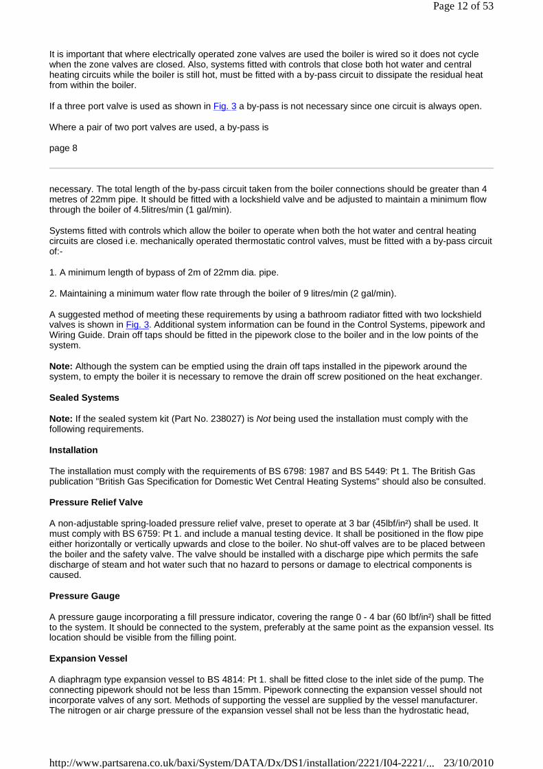
It is important that where electrically operated zone valves are used the boiler is wired so it does not cycle when the zone valves are closed. Also, systems fitted with controls that close both hot water and central heating circuits while the boiler is still hot, must be fitted with a by-pass circuit to dissipate the residual heat from within the boiler.
If a three port valve is used as shown in Fig. 3 a by-pass is not necessary since one circuit is always open.
Where a pair of two port valves are used, a by-pass is
page 8
necessary. The total length of the by-pass circuit taken from the boiler connections should be greater than 4 metres of 22mm pipe. It should be fitted with a lockshield valve and be adjusted to maintain a minimum flow through the boiler of 4.5litres/min (1 gal/min).
Systems fitted with controls which allow the boiler to operate when both the hot water and central heating circuits are closed i.e. mechanically operated thermostatic control valves, must be fitted with a by-pass circuit of:-
1. A minimum length of bypass of 2m of 22mm dia. pipe.
2. Maintaining a minimum water flow rate through the boiler of 9 litres/min (2 gal/min).
A suggested method of meeting these requirements by using a bathroom radiator fitted with two lockshield valves is shown in Fig. 3. Additional system information can be found in the Control Systems, pipework and Wiring Guide. Drain off taps should be fitted in the pipework close to the boiler and in the low points of the system.
Note: Although the system can be emptied using the drain off taps installed in the pipework around the system, to empty the boiler it is necessary to remove the drain off screw positioned on the heat exchanger.
Sealed Systems
Note: If the sealed system kit (Part No. 238027) is Not being used the installation must comply with the following requirements.
Installation
The installation must comply with the requirements of BS 6798: 1987 and BS 5449: Pt 1. The British Gas publication "British Gas Specification for Domestic Wet Central Heating Systems" should also be consulted.
Pressure Relief Valve
A non-adjustable spring-loaded pressure relief valve, preset to operate at 3 bar (45lbf/in²) shall be used. It must comply with BS 6759: Pt 1. and include a manual testing device. It shall be positioned in the flow pipe either horizontally or vertically upwards and close to the boiler. No shut-off valves are to be placed between the boiler and the safety valve. The valve should be installed with a discharge pipe which permits the safe discharge of steam and hot water such that no hazard to persons or damage to electrical components is caused.
Pressure Gauge
A pressure gauge incorporating a fill pressure indicator, covering the range 0 - 4 bar (60 lbf/in²) shall be fitted to the system. It should be connected to the system, preferably at the same point as the expansion vessel. Itslocation should be visible from the filling point.
Expansion Vessel
A diaphragm type expansion vessel to BS 4814: Pt 1. shall be fitted close to the inlet side of the pump. The connecting pipework should not be less than 15mm. Pipework connecting the expansion vessel should not incorporate valves of any sort. Methods of supporting the vessel are supplied by the vessel manufacturer. The nitrogen or air charge pressure of the expansion vessel shall not be less than the hydrostatic head,
Page 12 of 53
23/10/2010http://www.partsarena.co.uk/baxi/System/DATA/Dx/DS1/installation/2221/I04-2221/...
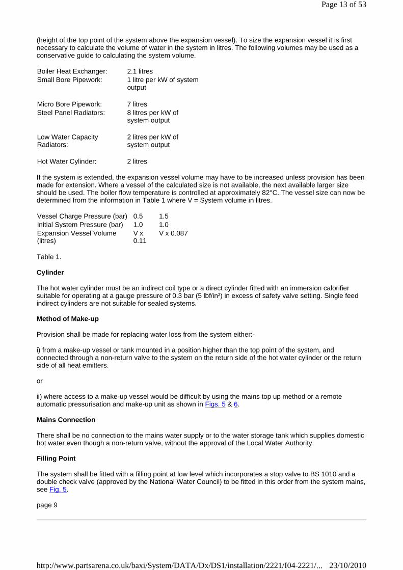
(height of the top point of the system above the expansion vessel). To size the expansion vessel it is first necessary to calculate the volume of water in the system in litres. The following volumes may be used as a conservative guide to calculating the system volume.
If the system is extended, the expansion vessel volume may have to be increased unless provision has been made for extension. Where a vessel of the calculated size is not available, the next available larger size should be used. The boiler flow temperature is controlled at approximately 82°C. The vessel size can now be determined from the information in Table 1 where V = System volume in litres.
Table 1.
Cylinder
The hot water cylinder must be an indirect coil type or a direct cylinder fitted with an immersion calorifier suitable for operating at a gauge pressure of 0.3 bar (5 lbf/in²) in excess of safety valve setting. Single feed indirect cylinders are not suitable for sealed systems.
Method of Make-up
Provision shall be made for replacing water loss from the system either:-
i) from a make-up vessel or tank mounted in a position higher than the top point of the system, and connected through a non-return valve to the system on the return side of the hot water cylinder or the return side of all heat emitters.
or
ii) where access to a make-up vessel would be difficult by using the mains top up method or a remote automatic pressurisation and make-up unit as shown in Figs. 5 & 6.
Mains Connection
There shall be no connection to the mains water supply or to the water storage tank which supplies domestic hot water even though a non-return valve, without the approval of the Local Water Authority.
Filling Point
The system shall be fitted with a filling point at low level which incorporates a stop valve to BS 1010 and a double check valve (approved by the National Water Council) to be fitted in this order from the system mains, see Fig. 5.
page 9
Boiler Heat Exchanger: 2.1 litres Small Bore Pipework: 1 litre per kW of system
output
Micro Bore Pipework: 7 litres Steel Panel Radiators: 8 litres per kW of
system output
Low Water Capacity Radiators:
2 litres per kW of system output
Hot Water Cylinder: 2 litres
Vessel Charge Pressure (bar) 0.5 1.5 Initial System Pressure (bar) 1.0 1.0 Expansion Vessel Volume (litres)
V x 0.11
V x 0.087
Page 13 of 53
23/10/2010http://www.partsarena.co.uk/baxi/System/DATA/Dx/DS1/installation/2221/I04-2221/...
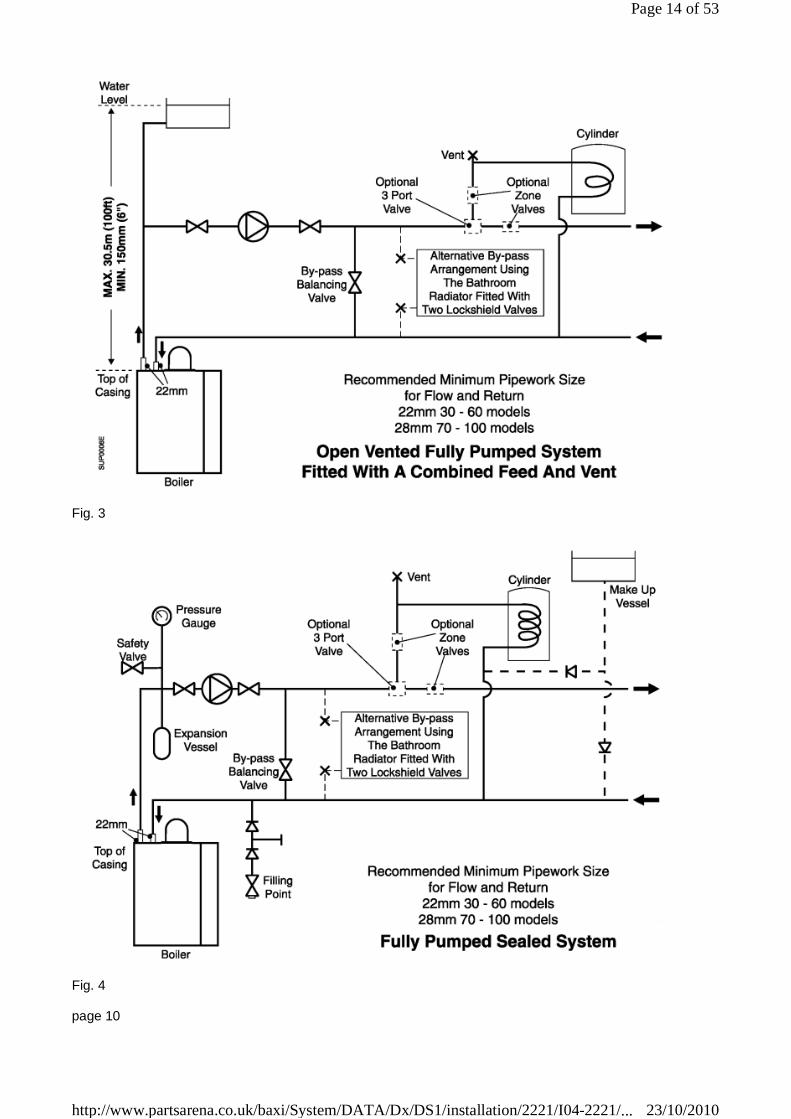
Fig. 3
Fig. 4
page 10
Page 14 of 53
23/10/2010http://www.partsarena.co.uk/baxi/System/DATA/Dx/DS1/installation/2221/I04-2221/...
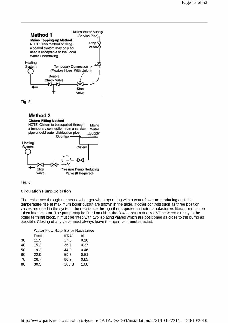
Fig. 5
Fig. 6
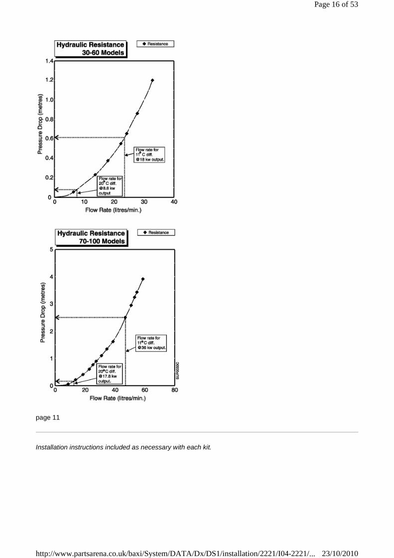
Circulation Pump Selection
The resistance through the heat exchanger when operating with a water flow rate producing an 11°C temperature rise at maximum boiler output are shown in the table. If other controls such as three position valves are used in the system, the resistance through them, quoted in their manufacturers literature must be taken into account. The pump may be fitted on either the flow or return and MUST be wired directly to the boiler terminal block. It must be fitted with two isolating valves which are positioned as close to the pump as possible. Closing of any valve must always leave the open vent unobstructed.
Water Flow Rate Boiler Resistance l/min mbar m 30 11.5 17.5 0.18 40 15.2 36.1 0.37 50 19.2 44.9 0.46 60 22.9 59.5 0.61 70 26.7 80.9 0.83 80 30.5 105.3 1.08
Page 15 of 53
23/10/2010http://www.partsarena.co.uk/baxi/System/DATA/Dx/DS1/installation/2221/I04-2221/...
page 11
Installation instructions included as necessary with each kit.
Page 16 of 53
23/10/2010http://www.partsarena.co.uk/baxi/System/DATA/Dx/DS1/installation/2221/I04-2221/...
page 12
Flue Kits
Page 17 of 53
23/10/2010http://www.partsarena.co.uk/baxi/System/DATA/Dx/DS1/installation/2221/I04-2221/...

Installation instructions included as necessary with each kit.
page 13
System and Other Kits
Page 18 of 53
23/10/2010http://www.partsarena.co.uk/baxi/System/DATA/Dx/DS1/installation/2221/I04-2221/...
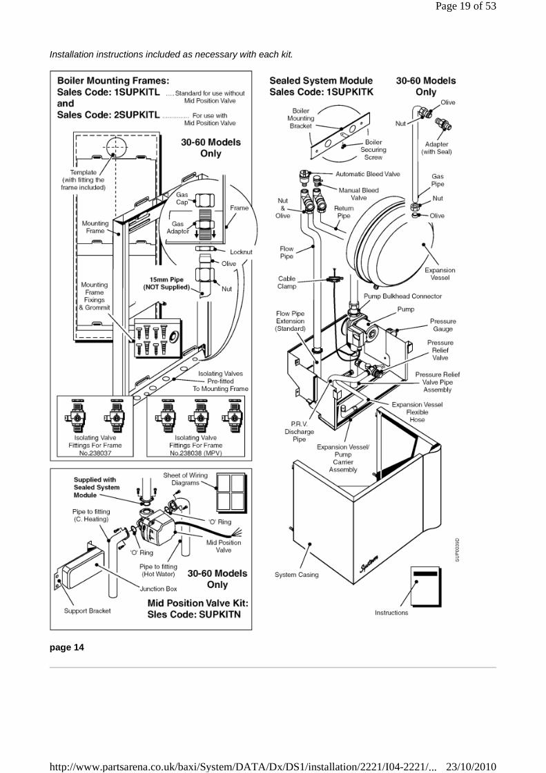
Installation instructions included as necessary with each kit.
page 14
Page 19 of 53
23/10/2010http://www.partsarena.co.uk/baxi/System/DATA/Dx/DS1/installation/2221/I04-2221/...
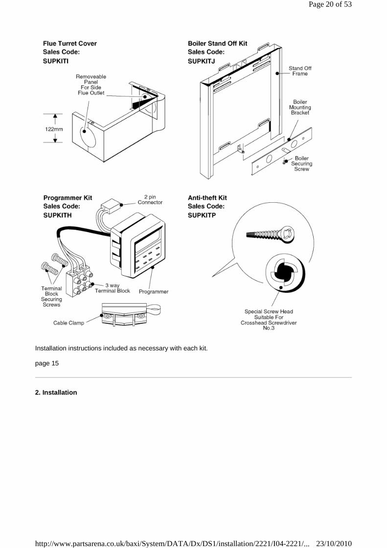
Installation instructions included as necessary with each kit.
page 15
2. Installation
Page 20 of 53
23/10/2010http://www.partsarena.co.uk/baxi/System/DATA/Dx/DS1/installation/2221/I04-2221/...

Fig. 7
2.1 Unpack & Prepare the Boiler
These instructions assume you have decided on where the boiler will be located and the type of flue system to be used.
1. Carefully unpack the boiler.
Page 21 of 53
23/10/2010http://www.partsarena.co.uk/baxi/System/DATA/Dx/DS1/installation/2221/I04-2221/...
2. Do not discard any packaging until all the items are accounted for.
3. Open the controls cover, remove the securing screw and washer, pull off the controls cover and put safely aside.
4. Remove two screws and washers, remove the white front case and put safely aside.
5. Place the mounting template in the proposed boiler position ensuring that it is level. Minimum clearances are accounted for on the template.
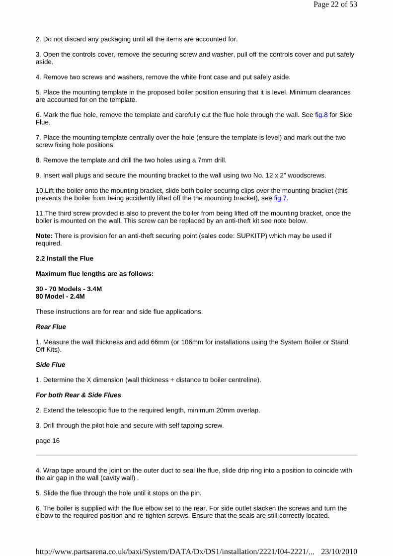
6. Mark the flue hole, remove the template and carefully cut the flue hole through the wall. See fig.8 for Side Flue.
7. Place the mounting template centrally over the hole (ensure the template is level) and mark out the two screw fixing hole positions.
8. Remove the template and drill the two holes using a 7mm drill.
9. Insert wall plugs and secure the mounting bracket to the wall using two No. 12 x 2" woodscrews.
10.Lift the boiler onto the mounting bracket, slide both boiler securing clips over the mounting bracket (this prevents the boiler from being accidently lifted off the the mounting bracket), see fig.7.
11.The third screw provided is also to prevent the boiler from being lifted off the mounting bracket, once the boiler is mounted on the wall. This screw can be replaced by an anti-theft kit see note below.
Note: There is provision for an anti-theft securing point (sales code: SUPKITP) which may be used if required.
2.2 Install the Flue
Maximum flue lengths are as follows:
30 - 70 Models - 3.4M 80 Model - 2.4M
These instructions are for rear and side flue applications.
Rear Flue
1. Measure the wall thickness and add 66mm (or 106mm for installations using the System Boiler or Stand Off Kits).
Side Flue
1. Determine the X dimension (wall thickness + distance to boiler centreline).
For both Rear & Side Flues
2. Extend the telescopic flue to the required length, minimum 20mm overlap.
3. Drill through the pilot hole and secure with self tapping screw.
page 16
4. Wrap tape around the joint on the outer duct to seal the flue, slide drip ring into a position to coincide with the air gap in the wall (cavity wall) .
5. Slide the flue through the hole until it stops on the pin.
6. The boiler is supplied with the flue elbow set to the rear. For side outlet slacken the screws and turn the elbow to the required position and re-tighten screws. Ensure that the seals are still correctly located.
Page 22 of 53
23/10/2010http://www.partsarena.co.uk/baxi/System/DATA/Dx/DS1/installation/2221/I04-2221/...
7. Hang the boiler onto the mounting bracket. To square the boiler to the wall adjust the boiler alignement screws on the back panel of the boiler.
8. Slide the flue back until it engages in the elbow bayonet connection, twist anticlockwise to lock.
9. Drill through pilot hole and lock flue in position with the self tapping screw provided.
10.Make good the wall around the flue, both outside and inside.
For extension kits refer to page 12 & 13. If a Horizontal Extension is required this MUST be combined with a Standard Flue as shown below in the Maximum Flue Length Guide.
If a in-line bend is required in the flue the following rules apply:
A 90° in-line bend is the equivalent to a 1m length of flue.
A 135° in-line bend is the equivalent to a ½m length of flue.
The maximum equivalent flue resistance allowed when using bends is:
30-70 models = 3.4m 80 model = 2.4m
Note: For flue lengths less than the minimum telescopic length, the tubes can be cut to suit. Ensure that the same length is removed from the inner and outer tubes to maintain a 20mm overlap (minimum).
For further information see 'Combination Flues' Publication No. 559979 or Vetex Flues' Publication No. 560039.
Page 23 of 53
23/10/2010http://www.partsarena.co.uk/baxi/System/DATA/Dx/DS1/installation/2221/I04-2221/...
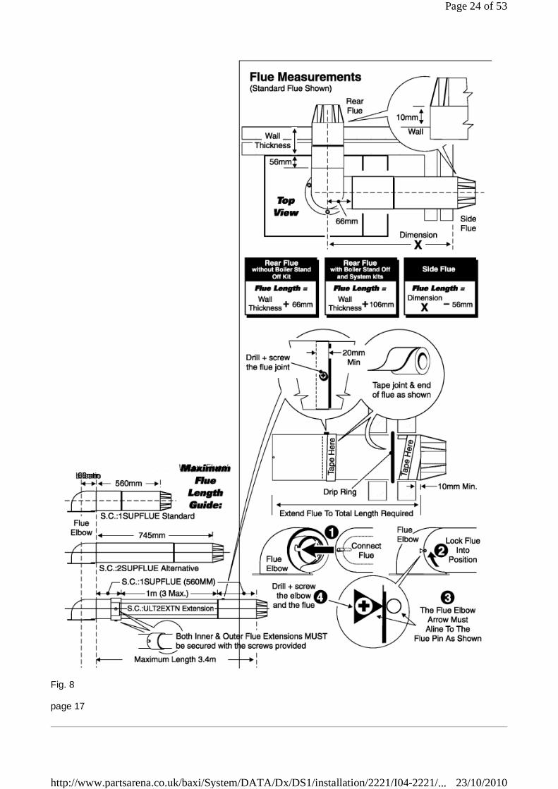
Fig. 8
page 17
Page 24 of 53
23/10/2010http://www.partsarena.co.uk/baxi/System/DATA/Dx/DS1/installation/2221/I04-2221/...

2.3 Connect the Power Supply Cable
1. Cable clamping is provided on the front of the controls panel. Feed the cables up and over the back of the chassis, through the clamp and into the terminal connection. Connect the wires, brown to L and blue to
N and green/yellow to earth ( ).
Note: When connecting the power supply cable, ensure that the length of the earth wire is such, that if the power supply cable pulls out of the cable clamp the live and neutral wires become taut before the earth wire.
2. The pump wiring should be routed through the hole in the base of the rear cover, through the cable clamp and connected to the terminal connection.
3. Take up excess slack in the cables between the terminal block and the cable clamp, then tighten the cable clamp screws. Ensure sufficient slack is available to the cable clamps to allow the control panel to hinge freely. Check by opening the control panel.
If fitting the optional Potterton timer go to section 2.4 before performing steps 4 and 5 below.
4. Secure the controls assembly to the chassis using the screw previously removed.
5. Carry out preliminary electrical system checks i.e. Earth Continuity, Short Circuit, Polarity and Resistance to Earth.
Frost Thermostat:
If a Frost Thermostat is to be fitted, the connections should be made in the wiring external to the boiler.
The Frost Thermostat should be connected between the Permanent Live & Switch Live in the supply cable to the boiler.
Do not switch on the electricity supply at this stage.
Page 25 of 53
23/10/2010http://www.partsarena.co.uk/baxi/System/DATA/Dx/DS1/installation/2221/I04-2221/...
Fig. 9
page 18
Page 26 of 53
23/10/2010http://www.partsarena.co.uk/baxi/System/DATA/Dx/DS1/installation/2221/I04-2221/...
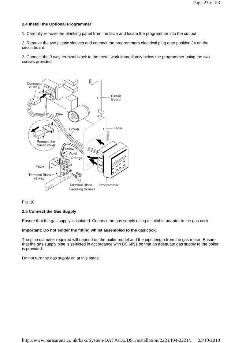
2.4 Install the Optional Programmer
1. Carefully remove the blanking panel from the facia and locate the programmer into the cut out.
2. Remove the two plastic sleeves and connect the programmers electrical plug onto position J4 on the circuit board.
3. Connect the 3 way terminal block to the metal work immediately below the programmer using the two screws provided.
Fig. 10
2.5 Connect the Gas Supply
Ensure that the gas supply is isolated. Connect the gas supply using a suitable adaptor to the gas cock.
Important: Do not solder the fitting whilst assembled to the gas cock.
The pipe diameter required will depend on the boiler model and the pipe length from the gas meter. Ensure that the gas supply pipe is selected in accordance with BS 6891 so that an adequate gas supply to the boiler is provided.
Do not turn the gas supply on at this stage.
Page 27 of 53
23/10/2010http://www.partsarena.co.uk/baxi/System/DATA/Dx/DS1/installation/2221/I04-2221/...
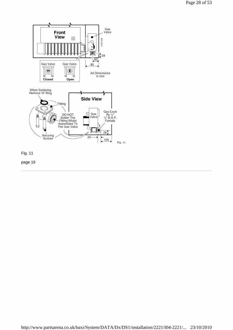
Fig. 11
page 19
Page 28 of 53
23/10/2010http://www.partsarena.co.uk/baxi/System/DATA/Dx/DS1/installation/2221/I04-2221/...

Fig. 12
2.6 Connect the Water System
1. Connect system pipework to the boiler, compression fittings should be used.
Page 29 of 53
23/10/2010http://www.partsarena.co.uk/baxi/System/DATA/Dx/DS1/installation/2221/I04-2221/...
Note: Drain off taps should be installed at the lowest points in the system.
page 20
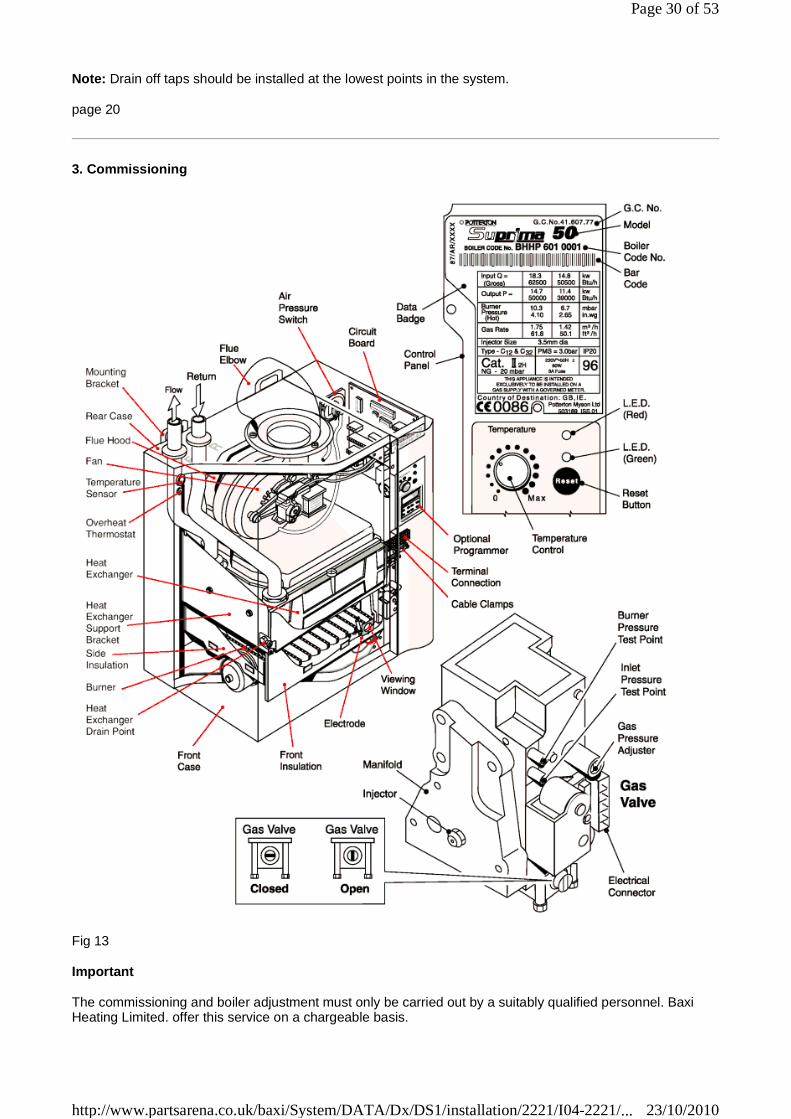
3. Commissioning
Fig 13
Important
The commissioning and boiler adjustment must only be carried out by a suitably qualified personnel. Baxi Heating Limited. offer this service on a chargeable basis.
Page 30 of 53
23/10/2010http://www.partsarena.co.uk/baxi/System/DATA/Dx/DS1/installation/2221/I04-2221/...

Important
When checking for gas soundness open all windows and doors in the room.
Extinguish all naked lights, cigarettes, pipes, etc.
page 21
3.1 Commission the Boiler
Open Vented Systems - Remove the pump and flush the system thoroughly with cold water. Re-fit the pump. Fill and vent the system then check for leaks.
Sealed Systems - Note: The system can be filled using a sealed system filler pump with a break tank or by any other method approved by the Local Water Authority. Remove the pump and flush the system thoroughly with cold water. Re-fit the pump. Fill and vent the system until the pressure gauge registers 1.5 bar (21.5 lbf/in²) and check for leaks. Raise the pressure until the safety valve lifts, this should occur within ± 0.3 bar of the preset lift pressure of 3 bar. Release water to attain the correct cold fill pressure.
All Systems
Warning: Before lighting the boiler, ensure that the outer white case has been correctly fitted and that the sealing strip fitted to the outer white case is forming a tight seal with the main boiler chassis. The controls cover is left off at this stage.
Preliminary electrical system checks. These checks must be carried out before attempting to light the boiler.
They are:- Earth Continuity, Short Circuit, Polarity & Resistance to Earth.
1) The whole of the gas installation must be checked for soundness and purged in accordance with BS 6891.
2) Set the boiler temperature control knob to 'O' Standby.
3) Turn the boiler gas service cock to the 'On' position and that the main gas supply is turned 'On'.
4) Make sure that the system is full of water and that the pump and radiator isolating valves are open. Vent air from the system.
5) Ensure that the main electricity supply is 'On'.
6) Check that the time control, if fitted, is in an 'On' position and that the room and cylinder thermostat, where fitted are set to high temperatures.
First time lighting:
7) Set the temperature control knob to its maximum setting.
The boiler will attempt to light, if the boiler does not light within 3 attempts (due to air in the system) the boiler controls will go to 'Lockout' and the upper Red LED on the control panel will go to a rapid flashing mode. To restart the lighting sequence press the reset button on the control panel. There will be a short delay before the lighting sequence starts.
When the boiler burner flame has established and the burner lights the lower Green LED on the user control panel will be on continuously.
LED Indicators Status Green
LED Red LED
Mains ON Only OFF ON Ext. Call for Heat (Boiler set to STNDBY, Temp.
FLASHING 2 Per Sec.
ON
Page 31 of 53
23/10/2010http://www.partsarena.co.uk/baxi/System/DATA/Dx/DS1/installation/2221/I04-2221/...
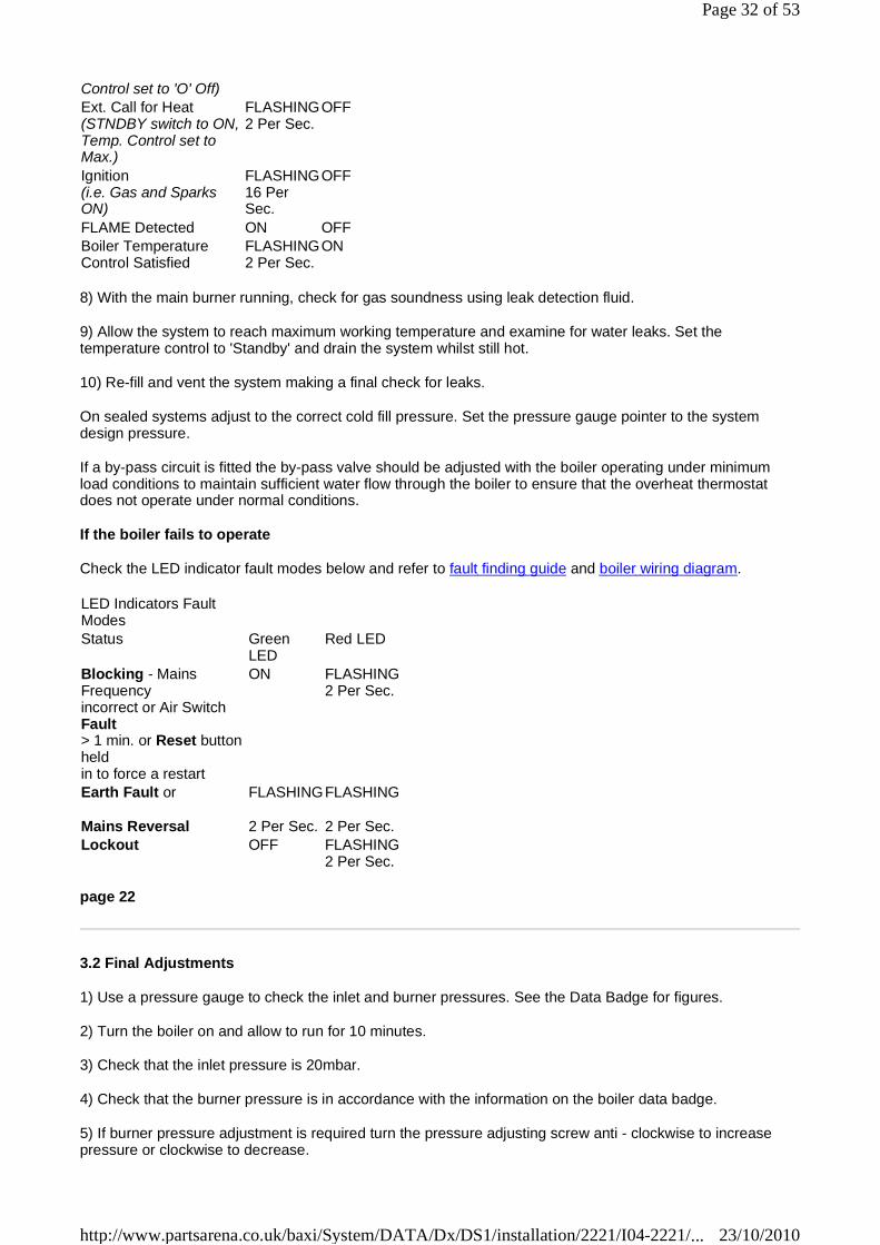
8) With the main burner running, check for gas soundness using leak detection fluid.
9) Allow the system to reach maximum working temperature and examine for water leaks. Set the temperature control to 'Standby' and drain the system whilst still hot.
10) Re-fill and vent the system making a final check for leaks.
On sealed systems adjust to the correct cold fill pressure. Set the pressure gauge pointer to the system design pressure.
If a by-pass circuit is fitted the by-pass valve should be adjusted with the boiler operating under minimum load conditions to maintain sufficient water flow through the boiler to ensure that the overheat thermostat does not operate under normal conditions.
If the boiler fails to operate
Check the LED indicator fault modes below and refer to fault finding guide and boiler wiring diagram.
page 22
3.2 Final Adjustments
1) Use a pressure gauge to check the inlet and burner pressures. See the Data Badge for figures.
2) Turn the boiler on and allow to run for 10 minutes.
3) Check that the inlet pressure is 20mbar.
4) Check that the burner pressure is in accordance with the information on the boiler data badge.
5) If burner pressure adjustment is required turn the pressure adjusting screw anti - clockwise to increase pressure or clockwise to decrease.
Control set to 'O' Off) Ext. Call for Heat (STNDBY switch to ON, Temp. Control set to Max.)
FLASHING 2 Per Sec.
OFF
Ignition (i.e. Gas and Sparks ON)
FLASHING 16 Per Sec.
OFF
FLAME Detected ON OFF Boiler Temperature Control Satisfied
FLASHING 2 Per Sec.
ON
LED Indicators Fault Modes
Status Green LED
Red LED
Blocking - Mains Frequency incorrect or Air Switch Fault > 1 min. or Reset button held in to force a restart
ON FLASHING 2 Per Sec.
Earth Fault or
Mains Reversal
FLASHING
2 Per Sec.
FLASHING
2 Per Sec. Lockout OFF FLASHING
2 Per Sec.
Page 32 of 53
23/10/2010http://www.partsarena.co.uk/baxi/System/DATA/Dx/DS1/installation/2221/I04-2221/...
6) Check at the gas meter that the gas rate is correct.
7) Shut down the boiler, remove the pressure gauges, re- fit the screws and check for gas soundness.
8) Stick the self adhesive arrow (from the literature pack) onto the data badge to indicate the appropriate burner setting pressure
9) Re-fit the controls cover and secure with the screw previously removed.
Control Thermostat
At its minimum and maximum settings, the thermostat should control the water flow temperature at approximately 57°C - 82°C.
Set the temperature control knob to 'O' Standby and check that the main burner shuts down.
Overheat Thermostat
The overheat thermostat is pre-set and no adjustment is possible. It will require manual re-setting if an overheat condition occurs (the LED will go to flashing Red).
The re-set button is located on the controls assembly.
Other Boiler Controls
No further setting or checking is necessary as all boiler mounted controls are designed so that if a fault should occur they will fail safe.
External Controls
Check that any other external controls connected in the system, such as clocks or thermostats, control the boiler as required.
3.3 Instruct the User
On completion of the installation, the installer should demonstrate the operation of the boiler and its associated controls. Also hand over all the instructions.
3.4 Advise the User
1. If a timer is fitted, set the time and programme the required settings. For a wall mounted programmer, see separate programmer instructions. For the Suprima timer, see the timer Instructions for Use fitted to the controls cover door.
2. Instruct the User in the safe operation of the boiler and controls.
3. Advise the User of the precautions necessary to prevent damage to the system and to the building in the event of the system remaining inoperative during frost conditions.
4. Advise the User that for continued efficient and safe operation of the boiler it is important that adequate servicing is carried out at least once a year by a Baxi Service Engineer, the local Gas Supplier or a C.O.R.G.I. Registered Installer.
5. Leave a permanent card attached to the boiler giving:
a. Name and address of installer. b. Date of installation. c. A wiring diagram of the external control circuit.
6. And finally, complete the Benchmark Log Book and hand over all the instructions supplied.
page 23
Page 33 of 53
23/10/2010http://www.partsarena.co.uk/baxi/System/DATA/Dx/DS1/installation/2221/I04-2221/...
4. To Service the Boiler & Component Replacement
To ensure continued efficient operation of the appliance, it is recommended that it is checked and cleaned as necessary at regular intervals.
The frequency of servicing will depend upon the particular installation conditions and usage but in general once per year should be adequate.
It is the law that any service work must be carried out by a competent person who is C.O.R.G.I. Registered.
Before servicing, fire the appliance and check that the flames are blue.
Yellow flame and excessive lifting indicate poor combustion.
WARNING
Before commencing work turn the temperature control knob to 'O' Off and allow the appliance to cool, isolate the electricity supply.
If the gas valve is to be removed turn off the gas supply at the appliance service cock.
IMPORTANT
Always test for gas soundness after completing any servicing of gas carrying components and carry out functional checks of controls.
IMPORTANT
Ensure that the outer white case is correctly fitted and that the sealing strip fitted to the door is forming a tight seal with the boiler casing.
Remember to fill in the Benchmark Log Book
Notes on Cleaning Boiler Components
Heat Exchanger
Place a sheet of paper under the heat exchanger then using a flat blade tool (Part No. 907736), scrape the flueway fin surfaces in a downward movement. This will ensure that most of the deposits will be collected on the paper.
Burner
Brush the burner top and check that the flame ports are clear. Any blockage may be removed with a fine wire brush. Turn the burner upside down and tap gently to remove any debris (Protect the electrode).
Electrode
If the electrode requires cleaning wipe the surface using a solvent.
Main Injector
Omit this operation if the gas rate is correct, otherwise clean by blowing through. Do NOT clear the injector with a pin or wire.
Fan Assembly
Examine the fan impellor and carefully clean if necessary.
Flue
Inspect the flue terminal and flue/air tube for blockage and integrity, rectify if necessary.
Page 34 of 53
23/10/2010http://www.partsarena.co.uk/baxi/System/DATA/Dx/DS1/installation/2221/I04-2221/...
4.1 General Access
Warning: Before starting work, open the controls cover and set the temperature control knob to 'O' Off. Isolate the electricity supply and if a gas carrying component is to be removed, isolate the gas supply at the appliance service cock. Allow the boiler to cool.
Important: Always test for gas soundness after completing any exchange of gas carrying components and carry out a functional check of the controls.
Re-assemble all parts in reverse order.
1. Remove the securing screw and slide off the controls cover. Put safely aside.
page 24
To complete sections 4.3.3 to 4.3.11 perform the following:-
2. Remove the two screws securing the outer white case to the chassis. Hinge forward, pull bottom of cover forward and lift off. Put safely aside.
3. Remove the screw securing the combustion chamber front to the heat exchanger and remove the panel.
4.2 To Service the Boiler
1. Note how it fits and disconnect the tube from the front of the fan housing.
2. Disconnect the 3 wires from the fan motor.
3. Remove the two screws securing the fan to the flue hood. Carefully pull the fan down and away from the flue hood.
4. Remove the flue hood.
5. Disconnect the electrode and earth wire.
6. Undo the fixing screw, hold the burner at the right hand side and pull forward to disconnect from the box.
If necessary, remove the injector as follows:-
7. Undo the two screws securing the side and rear insulation assembly on the front of the chassis. Pull the assembly forward and away from the boiler.
8. Remove the burner bracket (three screws) to give access to the injector.
9. Use a new sealing washer when re-fitting the injector.
The heat exchanger, burner and fan can now be inspected. If deposits have formed on these items and on ancillary components clean as detailed in the notes at the start of this section.
The boiler can be re-assembled in reverse order. Ensure that any electrical connections are in place and that any damaged seals or insulation are replaced before re-fitting the controls cover.
Check the gas pressure, refer to Section 3 'Commissioning'.
Other Components
No other servicing is required on any other boiler component.
Page 35 of 53
23/10/2010http://www.partsarena.co.uk/baxi/System/DATA/Dx/DS1/installation/2221/I04-2221/...
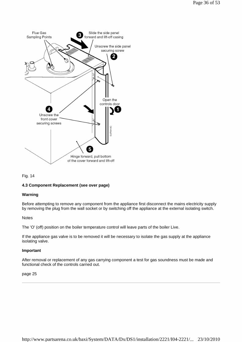
Fig. 14
4.3 Component Replacement (see over page)
Warning
Before attempting to remove any component from the appliance first disconnect the mains electricity supply by removing the plug from the wall socket or by switching off the appliance at the external isolating switch.
Notes
The 'O' (off) position on the boiler temperature control will leave parts of the boiler Live.
If the appliance gas valve is to be removed it will be necessary to isolate the gas supply at the appliance isolating valve.
Important
After removal or replacement of any gas carrying component a test for gas soundness must be made and functional check of the controls carried out.
page 25
Page 36 of 53
23/10/2010http://www.partsarena.co.uk/baxi/System/DATA/Dx/DS1/installation/2221/I04-2221/...
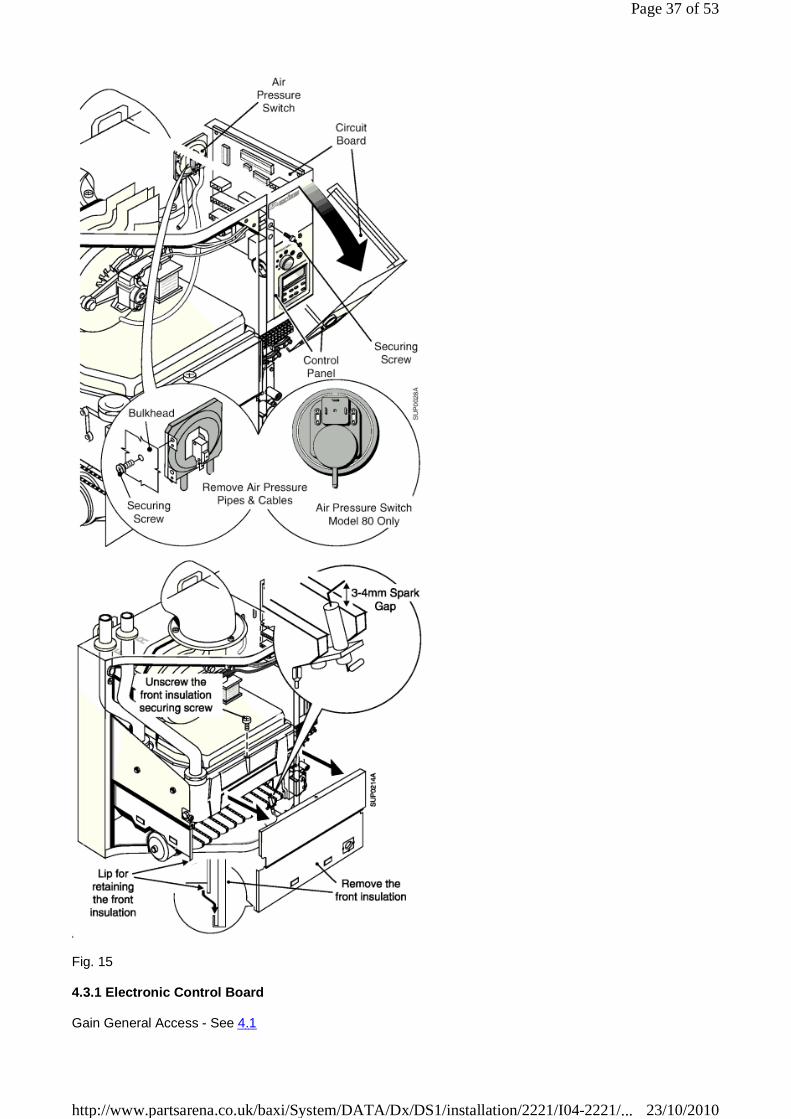
Fig. 15
4.3.1 Electronic Control Board
Gain General Access - See 4.1
Page 37 of 53
23/10/2010http://www.partsarena.co.uk/baxi/System/DATA/Dx/DS1/installation/2221/I04-2221/...

1. Remove the securing screw and allow the control panel to pivot forwards.
2. Disconnect all connectors and wires, unscrew the four securing screws and remove the board.
3. On re-assembly refer to the wiring diagram when re-connecting wires and connectors.
4.3.2 Air Pressure Switch
Gain General Access - See 4.1
1. Remove the securing screw and allow the control panel to pivot forwards.
2. Note the wire connections and disconnect the wires to the air pressure switch.
3. Remove the screw (access through the fan compartment) securing the air pressure switch to the chassis.
4. Re-assemble in reverse order, ensure that the Normally Closed (N.C) terminal is shrouded.
4.3.3 Electrode
Gain General Access - See 4.1
1. Pull the electrode lead off the electrode, remove the securing screw and remove the electrode.
2. On re-assembly check the gap between the electrode tip and the burner face. It should be 3 - 4mm. If required adjustment can be made by careful use of pliers.
page 26
4.3.4 Burner
Gain General Access - See 4.1
1. Disconnect the electrode lead and earth wire.
2. Undo the fixing screw, hold the burner at the right hand side and pull forwards to disconnect from the air box.
3. Unscrew the electrode and transfer to the new burner.
4. Re-assemble in reverse order, on reassembly hook the rear of the locating bracket (1) in place before locating the front (2).
4.3.5Injector
Gain General Access - See 4.1
1. Remove the burner - See 4.3.4.
2. Use a 13mm (A/F) or ½" (A/F) socket spanner to remove the injector.
3. Unscrew the injector, use a new sealing washer on re-assembly.
If using a flat spanner to remove the injector see the next section (4.3.6.)
4.3.6 Combustion Chamber Insulation
Gain General Access - See 4.1
1. The front insulation is accessible as the front is already off.
Page 38 of 53
23/10/2010http://www.partsarena.co.uk/baxi/System/DATA/Dx/DS1/installation/2221/I04-2221/...

2. Remove the burner - See 4.3.4.
3. Remove the two screws securing the side and rear insulation assembly to the front of the chassis.
4. Pull the assembly forwards and away from the boiler. Replace insulation pieces as required, replace any securing clip if damaged.
5. Re-assemble in reverse order.
Page 39 of 53
23/10/2010http://www.partsarena.co.uk/baxi/System/DATA/Dx/DS1/installation/2221/I04-2221/...

Fig. 16
page 27
Page 40 of 53
23/10/2010http://www.partsarena.co.uk/baxi/System/DATA/Dx/DS1/installation/2221/I04-2221/...
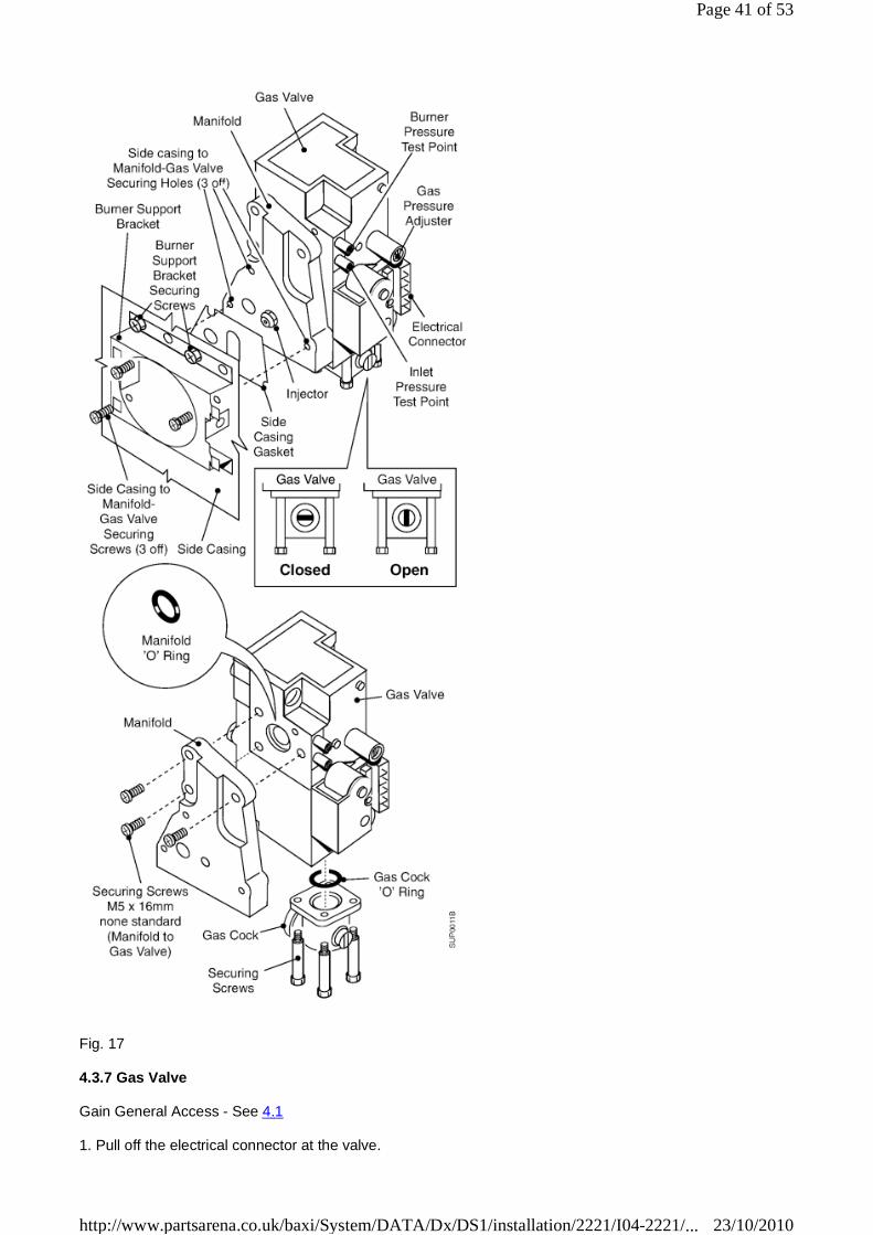
Fig. 17
4.3.7 Gas Valve
Gain General Access - See 4.1
1. Pull off the electrical connector at the valve.
Page 41 of 53
23/10/2010http://www.partsarena.co.uk/baxi/System/DATA/Dx/DS1/installation/2221/I04-2221/...
2. Remove the gas cock by unscrewing the four long hexagonal head screws from the base of the valve.
3. Remove the burner - See 4.3.4.
4. Remove the screw securing the controls assembly to the top of the valve.
5. Remove the two screws securing the side and rear insulation assembly to the front of the chassis and remove assembly.
6. Remove the three screws securing the gas valve manifold assembly to the chassis and remove the complete assembly.
7. Remove the three M5 x 16mm screws securing the gas manifold to the gas valve.
8. Use a new 'O' ring and refit the manifold to the new gas valve.
9. Re-assemble in reverse order, use a new side panel gasket and 'O' ring in the gas cock.
page 28
4.3.8 Fan & Flue Hood
Gain General Access - See 4.1
1. Disconnect the tube from the front of the fan housing - note how it fits.
2. Disconnect the three wires from the fan motor.
3. Remove the two screws securing the fan to the flue hood.
4. Carefully pull the fan down and away from the boiler.
5. Flue Hood: On re-assembly ensure that the flue hood locates under the two brackets at the rear of the chassis. Check the seal and replace if damaged.
6. Fan: On re-assembly ensure that the rubber seal around the fan opening is located correctly into the base of the flue elbow.
7. Re-assemble in reverse order.
Page 42 of 53
23/10/2010http://www.partsarena.co.uk/baxi/System/DATA/Dx/DS1/installation/2221/I04-2221/...
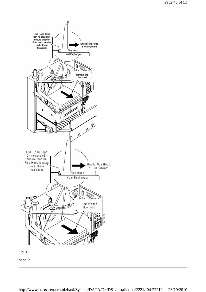
Fig. 18
page 29
Page 43 of 53
23/10/2010http://www.partsarena.co.uk/baxi/System/DATA/Dx/DS1/installation/2221/I04-2221/...

Fig. 19
4.3.9 Temperature Sensor
Gain General Access - See 4.1
1. Disconnect the wires from the sensor.
2. Depress the clips on the outside of the sensor and pull it clear of the pipe.
3. Re-assemble in reverse order, use fresh conducting paste.
4.3.10 Overheat Thermostat
Gain General Access - See 4.1
1. Disconnect the wires from the thermostat.
2. Unscrew the thermostat.
3. Re-assemble in reverse order.
page 30
Page 44 of 53
23/10/2010http://www.partsarena.co.uk/baxi/System/DATA/Dx/DS1/installation/2221/I04-2221/...
4.3.11 Heat Exchanger
Warning:
For Sealed Systems relieve system pressure through pressure relief valve before draining.
Gain General Access - See 4.1.
1. Drain the system at its lowest point.
2. Remove the fan and flue hood - See 4.8
3. Remove the burner - See 4.3.4.
4. Hold a suitable container under the left hand side of the heat exchanger and unscrew the drain screw. Drain the heat exchanger.
5. Remove the screws securing the combustion chamber insulation assembly to the chassis and withdraw it.
6. Release both the flow and return nuts at the top of the heat exchanger.
7. Support the heat exchanger, remove the four bolts (Two each side) and carefully remove the heat exchanger.
8. Replace rubber seals in flow and return ports, feed the new heat exchanger into position ensuring the pipe connections are correctly located.
9. Secure the heat exchanger with the four fixing screws and tighten the two sealing nuts.
10.Re-assemble in reverse order.
Page 45 of 53
23/10/2010http://www.partsarena.co.uk/baxi/System/DATA/Dx/DS1/installation/2221/I04-2221/...

Fig. 20
page 31
5. Functional Wiring Diagram
Boiler Lighting Sequence
1. Supply external voltage to boiler terminal connections L and N, 230 volts, 50 HZ.
2. Supply external voltage to boiler terminal connection, switch line SW 230 volts, 50 HZ.
3. Pump live from boiler energised, diverter/zone valves operate in accordance with system demand.
4. Boiler control checks, air pressure switch for "No Air Condition" (red light "On", green light "Flashing").
5. If "No Air" the control switches on the fan.
6. After ten seconds air pressure switch proves fan is on.
7. Gas valves open and ignition for 3 seconds (green light flashes rapidly).
8. Boiler firing (green light "On" only).
Page 46 of 53
23/10/2010http://www.partsarena.co.uk/baxi/System/DATA/Dx/DS1/installation/2221/I04-2221/...
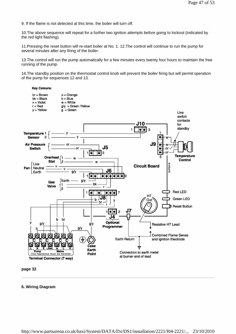
9. If the flame is not detected at this time, the boiler will turn off.
10.The above sequence will repeat for a further two ignition attempts before going to lockout (indicated by the red light flashing).
11.Pressing the reset button will re-start boiler at No. 1. 12.The control will continue to run the pump for several minutes after any firing of the boiler.
13.The control will run the pump automatically for a few minutes every twenty four hours to maintain the free running of the pump.
14.The standby position on the thermostat control knob will prevent the boiler firing but will permit operation of the pump for sequences 12 and 13.
page 32
6. Wiring Diagram
Page 47 of 53
23/10/2010http://www.partsarena.co.uk/baxi/System/DATA/Dx/DS1/installation/2221/I04-2221/...

page 33
7. Fault Finding Guide
Sequence of Events
Page 48 of 53
23/10/2010http://www.partsarena.co.uk/baxi/System/DATA/Dx/DS1/installation/2221/I04-2221/...
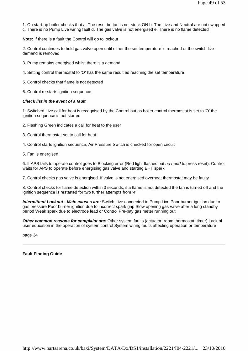
1. On start-up boiler checks that a. The reset button is not stuck ON b. The Live and Neutral are not swapped c. There is no Pump Live wiring fault d. The gas valve is not energised e. There is no flame detected
Note: If there is a fault the Control will go to lockout
2. Control continues to hold gas valve open until either the set temperature is reached or the switch live demand is removed
3. Pump remains energised whilst there is a demand
4. Setting control thermostat to 'O' has the same result as reaching the set temperature
5. Control checks that flame is not detected
6. Control re-starts ignition sequence
Check list in the event of a fault
1. Switched Live call for heat is recognised by the Control but as boiler control thermostat is set to 'O' the ignition sequence is not started
2. Flashing Green indicates a call for heat to the user
3. Control thermostat set to call for heat
4. Control starts ignition sequence, Air Pressure Switch is checked for open circuit
5. Fan is energised
6. If APS fails to operate control goes to Blocking error (Red light flashes but no need to press reset). Control waits for APS to operate before energising gas valve and starting EHT spark
7. Control checks gas valve is energised. If valve is not energised overheat thermostat may be faulty
8. Control checks for flame detection within 3 seconds, if a flame is not detected the fan is turned off and the ignition sequence is restarted for two further attempts from '4'
Intermittent Lockout - Main causes are: Switch Live connected to Pump Live Poor burner ignition due to gas pressure Poor burner ignition due to incorrect spark gap Slow opening gas valve after a long standby period Weak spark due to electrode lead or Control Pre-pay gas meter running out
Other common reasons for complaint are: Other system faults (actuator, room thermostat, timer) Lack of user education in the operation of system control System wiring faults affecting operation or temperature
page 34
Fault Finding Guide
Page 49 of 53
23/10/2010http://www.partsarena.co.uk/baxi/System/DATA/Dx/DS1/installation/2221/I04-2221/...

page 35
8. Short List Of Spare Parts
Page 50 of 53
23/10/2010http://www.partsarena.co.uk/baxi/System/DATA/Dx/DS1/installation/2221/I04-2221/...
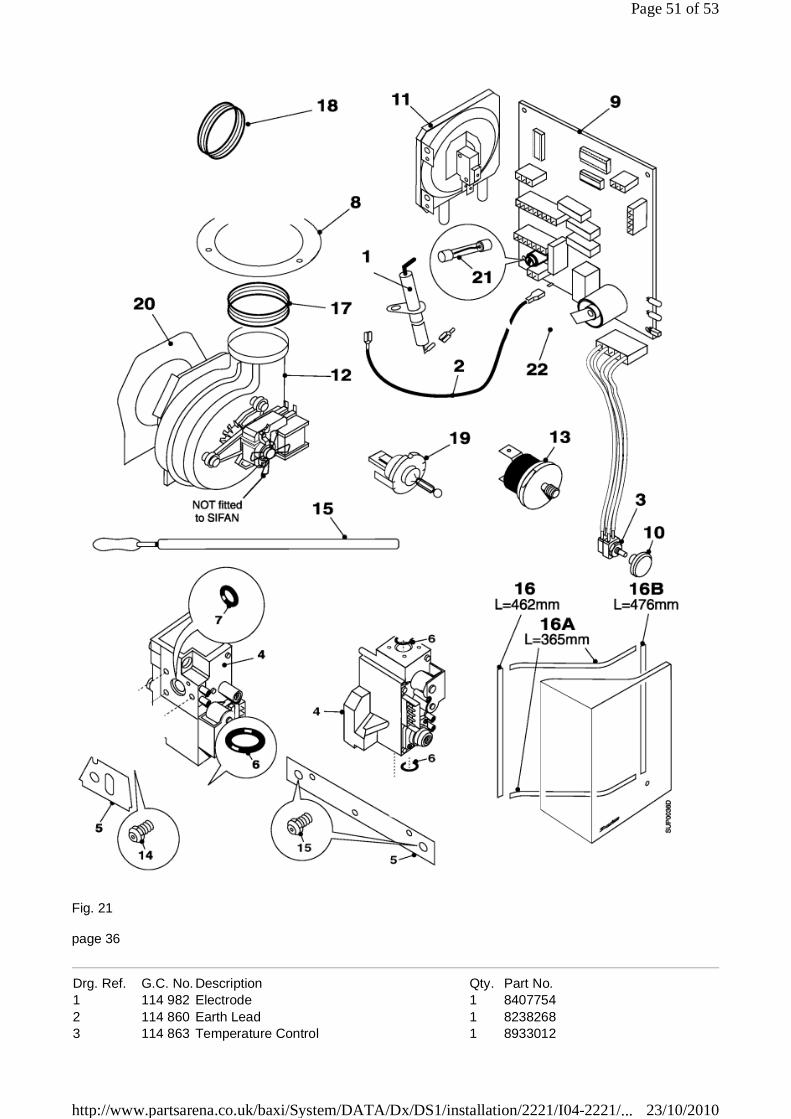
Fig. 21
page 36
Drg. Ref. G.C. No. Description Qty. Part No. 1 114 982 Electrode 1 8407754 2 114 860 Earth Lead 1 8238268 3 114 863 Temperature Control 1 8933012
Page 51 of 53
23/10/2010http://www.partsarena.co.uk/baxi/System/DATA/Dx/DS1/installation/2221/I04-2221/...
page 37
Notes
page 38
page 39
Sales Enquiries:
Sales Operations Eastern Avenue, Team Valley Trading Estate, Gateshead. Tyne & Wear. NE11 0PG.
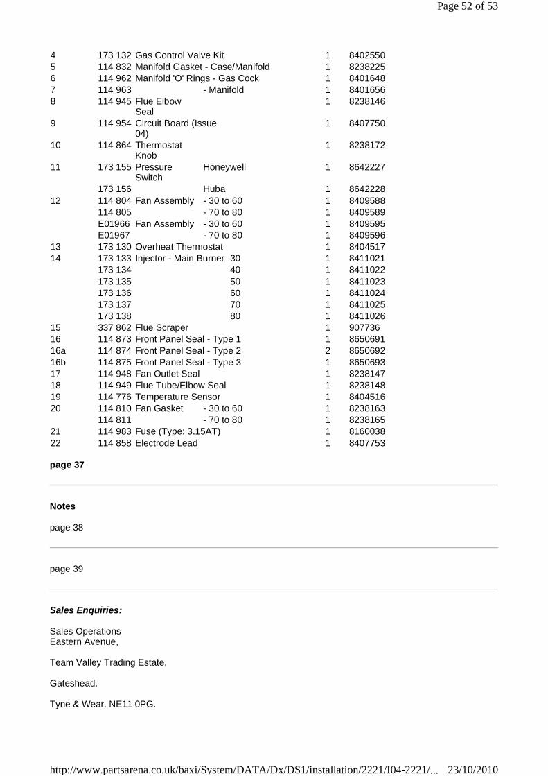
4 173 132 Gas Control Valve Kit 1 8402550 5 114 832 Manifold Gasket - Case/Manifold 1 8238225 6 114 962 Manifold 'O' Rings - Gas Cock 1 8401648 7 114 963 - Manifold 1 8401656 8 114 945 Flue Elbow
Seal 1 8238146
9 114 954 Circuit Board (Issue 04)
1 8407750
10 114 864 Thermostat Knob
1 8238172
11 173 155 Pressure Switch
Honeywell 1 8642227
173 156 Huba 1 8642228 12 114 804 Fan Assembly - 30 to 60 1 8409588 114 805 - 70 to 80 1 8409589 E01966 Fan Assembly - 30 to 60 1 8409595 E01967 - 70 to 80 1 8409596 13 173 130 Overheat Thermostat 1 8404517 14 173 133 Injector - Main Burner 30 1 8411021 173 134 40 1 8411022 173 135 50 1 8411023 173 136 60 1 8411024 173 137 70 1 8411025 173 138 80 1 8411026 15 337 862 Flue Scraper 1 907736 16 114 873 Front Panel Seal - Type 1 1 8650691 16a 114 874 Front Panel Seal - Type 2 2 8650692 16b 114 875 Front Panel Seal - Type 3 1 8650693 17 114 948 Fan Outlet Seal 1 8238147 18 114 949 Flue Tube/Elbow Seal 1 8238148 19 114 776 Temperature Sensor 1 8404516 20 114 810 Fan Gasket - 30 to 60 1 8238163 114 811 - 70 to 80 1 8238165 21 114 983 Fuse (Type: 3.15AT) 1 8160038 22 114 858 Electrode Lead 1 8407753
Page 52 of 53
23/10/2010http://www.partsarena.co.uk/baxi/System/DATA/Dx/DS1/installation/2221/I04-2221/...

Tel: 08706 060 403 Fax: 0191 491 7568
Service Enquiries:
Service Operations Brooks House, Coventry Road, Warwick. CV34 4LL.
Tel: 08706 096 096 * Fax: 01926 410006
Spares Enquiries:
Spare parts are available nationwide via the Interpart Stockists network.
For your local stockist consult Yellow Pages under Central Heating
Trade Support:
Trade Support Brooks House, Coventry Road, Warwick. CV34 4LL.
Tel: 08706 049 049 * Fax: 01926 410006
Training Administration:
National Training Administrator Tel: 0845 600 7402
Responsible for allocation and booking of all courses and activities at all training facilities in the UK
Brochure Hotline:
Tel: 08706 060 623
The Internet:
http://www.baxi.com http://www.potterton.co.uk
page 40
Page 53 of 53
23/10/2010http://www.partsarena.co.uk/baxi/System/DATA/Dx/DS1/installation/2221/I04-2221/...