potterton - performa he system - lets fixit · 2 publication no. 5111817 natural gas potterton...
TRANSCRIPT

Installation & Service Instructions PerformaSystem HE
This is a Wall Mounted Powered Flue Condensing Boiler Gas Fired Central Heating Unit.
The boiler meets the requirements of Statutory Instrument “ The Boiler (Efficiency) Regulations 1993 No 3083” and isdeemed to meet the requirements of Directive 92/42/EEC on the energy efficiency requirements for new hot waterboilers fired with liquid or gaseous fuels:-
Type test for purpose of Regulation 5 certified by: Notified Body 0051.
Product/Production certified by:Notified Body 0051.
For use in GB/IE only.
These instructions include the Benchmark Commissioning Checklist and should be left with the User for safe keeping.

Publication No. 51118172
Natural Gas
Potterton Performa System 12 HEG.C.No 41 591 24Potterton Performa System 18 HEG.C.No 41 591 25Potterton Performa System 24 HEG.C.No 41 591 26Potterton Performa System 28 HEG.C.No 41 591 27
This product has an energy rating (B) on a scale of A to G.For more information see www.boilers.org.uk. This is a certification mark.
Building Regulations and the BenchmarkCommissioning Checklist
Building Regulations (England & Wales) requirenotification of the installation of a heating appliance tothe relevant Local Authority Building ControlDepartment. From 1 April 2005 this can be achieved viaa Competent Persons Self Certification Scheme as anoption to notifying the Local Authority directly. Similararrangements will follow for Scotland and will apply inNorthern Ireland from 1 January 2006.
CORGI operate a Self Certification Scheme for gasheating appliances.
These arrangements represent a change from thesituation whereby compliance with Building Regulationswas accepted as being demonstrated by completion ofthe Benchmark Logbook (which was then left on sitewith the customer).
With the introduction of Self Certification Schemes, theBenchmark Logbook is being withdrawn. However, asimilar document in the form of a commissioningchecklist and service interval record is incorporated atthe back of these instructions.
Potterton is a member of the Benchmark initiative andfully supports the aims of the programme. Its aim is toimprove the standards of installation and commissioningof central heating systems in the UK and to encouragethe regular servicing of all central heating systems toensure safety and efficiency.
Building Regulations require that installations shouldcomply with manufacturer's instructions. It is thereforeimportant that the commissioning checklist is completedby the installer. The relevant section of BuildingRegulations only relates to dwellings. Therefore thechecklist only applies if the appliance is being installedin a dwelling or some related structure.
The flowchart opposite gives guidance for installers onthe process necessary to ensure compliance withBuilding Regulations.

3
INSTALLER NOTIFICATION GUIDELINES
Publication No. 5111817
Choose BuildingRegulations Notification
Route
Contact your relevant LocalAuthority Building Control(LABC) who will arrangean inspection or contacta government approved
inspector
LABC will record the dataand will issue a
certificate of compliance
CORGI will record the data andwill send a certificate of
compliance to the property
You must ensure that thenotification number issued by
CORGI is writen onto theBenchmark Checklist
Scheme Members only
Call CORGI on: 0870 88 88 777or log onto:
www.corgi-notify.comwithin 10 days
If you notify via CORGI Scheme,CORGI will then notify the
relevant Local AuthorityBuilding Control Scheme
on member's behalf
Complete theBenchmark Checklist
Install and Commission thisappliance to manufacturer's
instructions
Competent Person'sSelf Certification Scheme Building Control

LEGISLATION
4 Publication No. 5111817
Codes of Practice, most recent version shouldbe used
IMPORTANT - Installation, Commissioning, Service & Repair
This appliance must be installed in accordance with the manufacturer’sinstructions and the regulations in force. Read the instructions fully beforeinstalling or using the appliance.
In GB, this must be carried out by a competent person as stated in the GasSafety (Installation & Use) Regulations.
Definition of competence: A person who works for a CORGI registeredcompany and holding current certificates in the relevant ACS modules, isdeemed competent.
In IE, this must be carried out by a competent person as stated in I.S. 813“Domestic Gas Installations”.
Lifting - This product should be lifted and handled by two people. Stoopingshould be avoided and protective equipment worn where necessary. Carrying& lifting equipment should be used as required, e.g. when installing in in a loftspace.
The addition of anything that may interfere with the normal operation of theappliance without express written permission from the manufacturer or hisagent could invalidate the appliance warranty. In GB this could also infringethe Gas Safety (Installation and Use) Regulations.
Warning - Check the information on the data plate is compatible with localsupply conditions.
All CORGI registered installers carry a CORGI identification card and have aregistration number. You can check your installer is registered by telephoning0870 4012300 or writing to:-
1 Elmwood,Chineham Business Park,
Crockford Lane,Basingstoke. RG24 8WG
or check online at www.corgi-gas-safety.com
Potterton declare that no substances harmful tohealth are contained in the appliance or usedduring appliance manufacture.
The appliance is suitable only for installation in GBand IE and should be installed in accordance withthe rules in force, and only used in a suitablyventilated location.
In GB, the installation must be carried out by a CORGIRegistered Installer. It must be carried out in accordancewith the relevant requirements of the:• Gas Safety (Installation & Use) Regulations.• The appropriate Building Regulations either The
Building Regulations, The Building Regulations (Scotland), Building Regulations (Northern Ireland).
• The Water Fittings Regulations or Water Byelaws in Scotland.
• The Current I.E.E. Wiring Regulations.
Where no specific instructions are given, referenceshould be made to the relevant British Standard Code ofPractice.
In IE, the installation must be carried out by a competentPerson and installed in accordance with the currentedition of I.S. 813 ‘Domestic Gas Installations’, thecurrent Building Regulations and reference should bemade to the current ETCI rules for electrical installation.
All systems must be thoroughly flushed andtreated with inhibitor (see section 6.1).
In GB the following Codes of Practice apply:Standard ScopeBS 6891 Gas Installation.BS 5546 Installation of hot water supplies for
domestic purposes.BS 5449 Forced circulation hot water systems.BS 6798 Installation of gas fired hot water boilers.BS 5440 Part 1 Flues.BS 5440 Part 2 Ventilation.BS 7074 Expansion vessels and ancillary equipment
for sealed water systems.BS 7593 Treatment of water in domestic hot water
central heating systems.
In IE the following Codes of Practice apply:Standard ScopeI.S. 813 Domestic Gas Installations.The following BS standards give valuable additional information;BS 5546 Installation of hot water supplies for
domestic purposes.BS 5449 Forced circulation hot water systems.BS 7074 Expansion vessels and ancillary equipment
for sealed water systems.BS 7593 Treatment of water in domestic hot water
central heating systems.

5
CONTENTS
Publication No. 5111817
1.0 Introduction 6
2.0 General Layout 7
3.0 Appliance Operation 8
4.0 Technical Data 9
5.0 Dimensions and Fixings 13
6.0 System Details 14
7.0 Site Requirements 16
8.0 Installation 22
9.0 Commissioning 27
10.0 Completion 29
11.0 Servicing 30
12.0 Changing Components 32
13.0 Electrical 41
14.0 Short Parts List 42
15.0 Fault Finding 43
Benchmark Checklist 46
Section Page

1.0 INTRODUCTION
6 Publication No. 5111817
1.1 Description
1. The Potterton Performa System HE range are fullyautomatic gas fired wall mounted system boilers.They are room sealed and fan assisted.
2. The boilers are set to give a maximum output of 12.5kW, 18.9kW, 25.2kW or 29.3kW when incondensing mode.
3. They are designed for use on Natural Gas (G20)and can be converted to use Propane.
4. The boiler incorporates a circulating pump andexpansion vessel. It is suitable for use only on fullypumped sealed systems.
5. The boiler data badge gives details of the model,serial number and Gas Council number and issituated on the control box. It is visible when the casefront panel is removed (Fig. 1).
6. The boiler is intended to be installed in residential /commercial / light industrial E.M.C. environments on agoverned meter supply only.
7. The boiler must be installed with one of thepurpose designed flues such as the standardhorizontal flue kit, part no. 5111073
8. All systems must be thoroughly flushed andtreated with inhibitor (see section 6.1).
1.2 Optional Extras
Various flue extensions, bends, vertical fluekits,control accessories etc. are available as optionalextras. These are detailed in a separate publication.
NOTE: There are several detail differencesbetween each model. Generally these do notaffect the installation or maintenance of the boiler,unless otherwise stated.
Data Badge
Fig. 1
Control Box
Case Front Panel

7
2.0 GENERAL LAYOUT
Publication No. 5111817
2.1 Layout
1. Air Pressure Switch
2. Expansion Vessel
3. Burner Manifold
4. Automatic Air Vent
5. Circulation Pump
6. Drain Off Point
7. Pressure Relief Valve
8. System Pressure Gauge
9. PCB
10. Control Box
11. Condensate Trap
12. Flame Sensing Electrode
13. Spark Electrode
14. Burner
15. Primary Heat Exchanger
16. Fan Assembly
17. Secondary Heat Exchanger
18. On/Off/Reset Selector Switch
19. Temperature Control
20. Flame Failure or Blocked Condensate Drain
21. Safety Thermostat Activated (Boiler or Flue)
22. Fault on Fan or Flue
23. Fault on Pump or Low System Pressure
24. Fault on Temperature Sensor
25. Fault on Temperature Sensor
26. Power On
27. Boiler On
28. Burner On
When neons 20 to 25 are constantly illuminated, theyindicate the temperature of the central heating water.
16
15
14
11
12
13
10 98
18 19 8
6
5
3
4
7
2
1
2
1
0 4
3
bar
30° 40° 50° 60° 70° 80°
Reset
30° 40° 50° 60° 70° 80°
20 21 22 23 25
26 27 28
24
17
3.0 APPLIANCE OPERATION
8 Publication No. 5111817
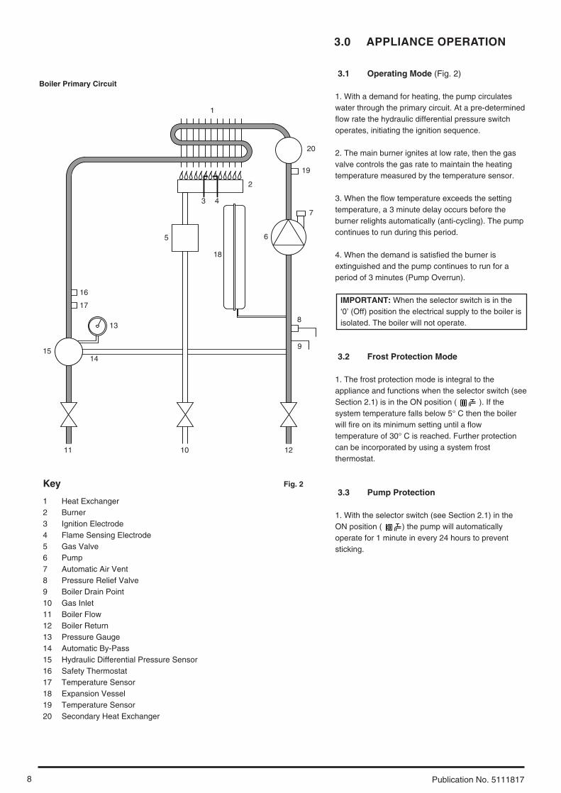
3.1 Operating Mode (Fig. 2)
1. With a demand for heating, the pump circulateswater through the primary circuit. At a pre-determinedflow rate the hydraulic differential pressure switchoperates, initiating the ignition sequence.
2. The main burner ignites at low rate, then the gasvalve controls the gas rate to maintain the heatingtemperature measured by the temperature sensor.
3. When the flow temperature exceeds the settingtemperature, a 3 minute delay occurs before theburner relights automatically (anti-cycling). The pumpcontinues to run during this period.
4. When the demand is satisfied the burner isextinguished and the pump continues to run for aperiod of 3 minutes (Pump Overrun).
IMPORTANT: When the selector switch is in the‘0’ (Off) position the electrical supply to the boiler isisolated. The boiler will not operate.
3.2 Frost Protection Mode
1. The frost protection mode is integral to theappliance and functions when the selector switch (seeSection 2.1) is in the ON position ( ). If thesystem temperature falls below 5° C then the boilerwill fire on its minimum setting until a flowtemperature of 30° C is reached. Further protectioncan be incorporated by using a system frostthermostat.
3.3 Pump Protection
1. With the selector switch (see Section 2.1) in theON position ( ) the pump will automaticallyoperate for 1 minute in every 24 hours to preventsticking.
1
2
4
5 6
7
8
19
18
9
10 12 11
14
13
15
16
17
3
Key
1 Heat Exchanger2 Burner 3 Ignition Electrode4 Flame Sensing Electrode5 Gas Valve6 Pump7 Automatic Air Vent8 Pressure Relief Valve9 Boiler Drain Point10 Gas Inlet11 Boiler Flow12 Boiler Return13 Pressure Gauge14 Automatic By-Pass15 Hydraulic Differential Pressure Sensor16 Safety Thermostat17 Temperature Sensor18 Expansion Vessel19 Temperature Sensor20 Secondary Heat Exchanger
Boiler Primary Circuit
Fig. 2
20

9
4.0 TECHNICAL DATA
Publication No. 5111817
4.1 System 12 HE
Flue Terminal Diameter 100mmDimensions Projection 125mm
Outercase DimensionsCasing Height - 780mmOverall Height Inc FlueElbow - 965mmCasing Width - 450mmCasing Depth - 345mm
ClearancesAbove Casing 200 mm MinBelow Casing 200 mm MinFront 450 mm Min (For Servicing)Front 5 mm Min (In Operation)L.H. Side 5mm MinR.H. Side 5mm Min (In Operation)
20mm Min (See Note*)
*NOTE: The boiler can be operated with aclearance of 5mm at the right. This is alsosufficient for routine maintenance.However a clearance of 20mm is requiredif it is necessary to remove the secondaryheat exchanger. This should beconsidered when siting the appliance andin the event of any subsequent alterationsin the area of installation
Weights kgPackaged Boiler Carton 48.5Installation Lift Weight 38
Central Heating Primary CircuitPressures
barSafety Discharge 3Max Operating 2.5Min Operating 0.5Recommend Operating 1-2
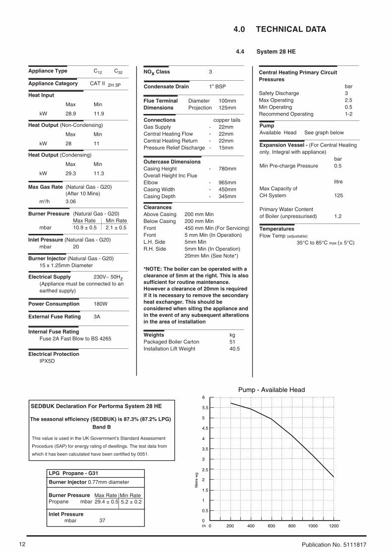
PumpAvailable Head See graph below
Expansion Vessel - (For Central Heatingonly. Integral with appliance)
barMin Pre-charge Pressure 0.5
litreMax Capacity of CH System 125
Primary Water Contentof Boiler (unpressurised) 1.2
Connections copper tailsGas Supply - 22mmCentral Heating Flow - 22mmCentral Heating Return - 22mmPressure Relief Discharge - 15mm
TemperaturesFlow Temp (adjustable)
35°C to 85°C max (± 5°C)
Heat Input
Max Min
kW 12.6 7
Electrical Supply 230V~ 50Hz (Appliance must be connected to an earthed supply)
Power Consumption 140W
External Fuse Rating 3A
Internal Fuse Rating Fuse 2A Fast Blow to BS 4265
Appliance Category CAT II 2H 3P
Max Gas Rate (Natural Gas - G20)(After 10 Mins)
m3/h 1.33
Inlet Pressure (Natural Gas - G20)mbar 20
Burner Injector (Natural Gas - G20)10 x 1.18mm Diameter
Burner Pressure (Natural Gas - G20)Max Rate Min Rate
mbar 5.7 ± 0.5 1.9 ± 0.5
Appliance Type C12 C32 NOx Class 3
Electrical ProtectionIPX5D
Heat Output (Non-Condensing)
Max Min
kW 12 6.5
Heat Output (Condensing)
Max Min
kW 12.5 6.7
Condensate Drain 1” BSP
0200 400 600 800 1000 1200
0.5
1
1.5
2
2.5
3
3.5
4
Met
re (
wg)
Flow Rate (l/h)
Pump - Available Head
0
5
4.5
This value is used in the UK Government’s Standard Assessment
Procedure (SAP) for energy rating of dwellings. The test data from
which it has been calculated have been certified by 0051.
SEDBUK Declaration For Performa System 12 HE
The seasonal efficiency (SEDBUK) is 86.8% (86.6% LPG)
Band B
LPG Propane - G31
Burner Injector 0.69mm diameter
Burner PressurePropane mbar
Inlet Pressurembar
Max Rate23.4 ± 0.5
Min Rate7.4 ± 0.2
37

4.0 TECHNICAL DATA
10 Publication No. 5111817
4.2 System 18 HE
Flue Terminal Diameter 100mmDimensions Projection 125mm
Outercase DimensionsCasing Height - 780mmOverall Height Inc FlueElbow - 965mmCasing Width - 450mmCasing Depth - 345mm
ClearancesAbove Casing 200 mm MinBelow Casing 200 mm MinFront 450 mm Min (For Servicing)Front 5 mm Min (In Operation)L.H. Side 5mm MinR.H. Side 5mm Min (In Operation)
20mm Min (See Note*)
*NOTE: The boiler can be operated with aclearance of 5mm at the right. This is alsosufficient for routine maintenance.However a clearance of 20mm is requiredif it is necessary to remove the secondaryheat exchanger. This should beconsidered when siting the appliance andin the event of any subsequent alterationsin the area of installation
Weights kgPackaged Boiler Carton 49Installation Lift Weight 38.5
Central Heating Primary CircuitPressures
barSafety Discharge 3Max Operating 2.5Min Operating 0.5Recommend Operating 1-2
PumpAvailable Head See graph below
Expansion Vessel - (For Central Heatingonly. Integral with appliance)
barMin Pre-charge Pressure 0.5
litreMax Capacity of CH System 125
Primary Water Contentof Boiler (unpressurised) 1.2
Connections copper tailsGas Supply - 22mmCentral Heating Flow - 22mmCentral Heating Return - 22mmPressure Relief Discharge - 15mm
TemperaturesFlow Temp (adjustable)
35°C to 85°C max (± 5°C)
Heat Input
Max Min
kW 18.7 10.6
Electrical Supply 230V~ 50Hz (Appliance must be connected to an earthed supply)
Power Consumption 140W
External Fuse Rating 3A
Internal Fuse Rating Fuse 2A Fast Blow to BS 4265
Appliance Category CAT II 2H 3P
Max Gas Rate (Natural Gas - G20)(After 10 Mins)
m3/h 1.98
Inlet Pressure (Natural Gas - G20)mbar 20
Burner Injector (Natural Gas - G20)12 x 1.18mm Diameter
Burner Pressure (Natural Gas - G20)Max Rate Min Rate
mbar 8.6 ± 0.5 3 ± 0.5
Appliance Type C12 C32 NOx Class 3
Electrical ProtectionIPX5D
Heat Output (Non-Condensing)
Max Min
kW 18 9.9
Heat Output (Condensing)
Max Min
kW 18.9 10.2
Condensate Drain 1” BSP
0200 400 600 800 1000 1200
0.5
1
1.5
2
2.5
3
3.5
4
Met
re (
wg)
Flow Rate (l/h)
Pump - Available Head
0
5
4.5
This value is used in the UK Government’s Standard Assessment
Procedure (SAP) for energy rating of dwellings. The test data from
which it has been calculated have been certified by 0051.
SEDBUK Declaration For Performa System 18 HE
The seasonal efficiency (SEDBUK) is 87.4% (87.3% LPG)
Band B
LPG Propane - G31
Burner Injector 0.77mm diameter
Burner PressurePropane mbar
Inlet Pressurembar
Max Rate20 ± 0.5
Min Rate6.6 ± 0.2
37

11
4.0 TECHNICAL DATA
Publication No. 5111817
4.3 System 24 HE
Flue Terminal Diameter 100mmDimensions Projection 125mm
Outercase DimensionsCasing Height - 780mmOverall Height Inc FlueElbow - 965mmCasing Width - 450mmCasing Depth - 345mm
ClearancesAbove Casing 200 mm MinBelow Casing 200 mm MinFront 450 mm Min (For Servicing)Front 5 mm Min (In Operation)L.H. Side 5mm MinR.H. Side 5mm Min (In Operation)
20mm Min (See Note*)
*NOTE: The boiler can be operated with aclearance of 5mm at the right. This is alsosufficient for routine maintenance.However a clearance of 20mm is requiredif it is necessary to remove the secondaryheat exchanger. This should beconsidered when siting the appliance andin the event of any subsequent alterationsin the area of installation
Weights kgPackaged Boiler Carton 51Installation Lift Weight 40.5
Central Heating Primary CircuitPressures
barSafety Discharge 3Max Operating 2.5Min Operating 0.5Recommend Operating 1-2
PumpAvailable Head See graph below
Expansion Vessel - (For Central Heatingonly. Integral with appliance)
barMin Pre-charge Pressure 0.5
litreMax Capacity of CH System 125
Primary Water Contentof Boiler (unpressurised) 1.2
Connections copper tailsGas Supply - 22mmCentral Heating Flow - 22mmCentral Heating Return - 22mmPressure Relief Discharge - 15mm
TemperaturesFlow Temp (adjustable)
35°C to 85°C max (± 5°C)
Heat Input
Max Min
kW 24.8 10.6
Electrical Supply 230V~ 50Hz (Appliance must be connected to an earthed supply)
Power Consumption 170W
External Fuse Rating 3A
Internal Fuse Rating Fuse 2A Fast Blow to BS 4265
Appliance Category CAT II 2H 3P
Max Gas Rate (Natural Gas - G20)(After 10 Mins)
m3/h 2.62
Inlet Pressure (Natural Gas - G20)mbar 20
Burner Injector (Natural Gas - G20)15 x 1.18mm Diameter
Burner Pressure (Natural Gas - G20)Max Rate Min Rate
mbar 10.2 ± 0.5 2 ± 0.5
Appliance Type C12 C32 NOx Class 3
Electrical ProtectionIPX5D
Heat Output (Non-Condensing)
Max Min
kW 24 9.8
Heat Output (Condensing)
Max Min
kW 25.2 10.1
Condensate Drain 1” BSP
0200 400 600 800 1000 1200
0.5
1
1.5
2
2.5
3
3.5
4
4.5
5
5.5
6
Met
re w
g
l/h
Pump - Available Head
0
This value is used in the UK Government’s Standard Assessment
Procedure (SAP) for energy rating of dwellings. The test data from
which it has been calculated have been certified by 0051.
SEDBUK Declaration For Performa System 24 HE
The seasonal efficiency (SEDBUK) is 87.4% (87.2% LPG)
Band B
LPG Propane - G31
Burner Injector 0.77mm diameter
Burner PressurePropane mbar
Inlet Pressurembar
Max Rate21.8 ± 0.5
Min Rate4.4 ± 0.2
37
4.0 TECHNICAL DATA
12 Publication No. 5111817
4.4 System 28 HE
Flue Terminal Diameter 100mmDimensions Projection 125mm
Outercase DimensionsCasing Height - 780mmOverall Height Inc FlueElbow - 965mmCasing Width - 450mmCasing Depth - 345mm
ClearancesAbove Casing 200 mm MinBelow Casing 200 mm MinFront 450 mm Min (For Servicing)Front 5 mm Min (In Operation)L.H. Side 5mm MinR.H. Side 5mm Min (In Operation)
20mm Min (See Note*)
*NOTE: The boiler can be operated with aclearance of 5mm at the right. This is alsosufficient for routine maintenance.However a clearance of 20mm is requiredif it is necessary to remove the secondaryheat exchanger. This should beconsidered when siting the appliance andin the event of any subsequent alterationsin the area of installation
Weights kgPackaged Boiler Carton 51Installation Lift Weight 40.5
Central Heating Primary CircuitPressures
barSafety Discharge 3Max Operating 2.5Min Operating 0.5Recommend Operating 1-2
PumpAvailable Head See graph below
Expansion Vessel - (For Central Heatingonly. Integral with appliance)
barMin Pre-charge Pressure 0.5
litreMax Capacity of CH System 125
Primary Water Contentof Boiler (unpressurised) 1.2
Connections copper tailsGas Supply - 22mmCentral Heating Flow - 22mmCentral Heating Return - 22mmPressure Relief Discharge - 15mm
TemperaturesFlow Temp (adjustable)
35°C to 85°C max (± 5°C)
Heat Input
Max Min
kW 28.9 11.9
Electrical Supply 230V~ 50Hz (Appliance must be connected to an earthed supply)
Power Consumption 180W
External Fuse Rating 3A
Internal Fuse Rating Fuse 2A Fast Blow to BS 4265
Appliance Category CAT II 2H 3P
Max Gas Rate (Natural Gas - G20)(After 10 Mins)
m3/h 3.06
Inlet Pressure (Natural Gas - G20)mbar 20
Burner Injector (Natural Gas - G20)15 x 1.25mm Diameter
Burner Pressure (Natural Gas - G20)Max Rate Min Rate
mbar 10.9 ± 0.5 2.1 ± 0.5
Appliance Type C12 C32 NOx Class 3
Electrical ProtectionIPX5D
Heat Output (Non-Condensing)
Max Min
kW 28 11
Heat Output (Condensing)
Max Min
kW 29.3 11.3
Condensate Drain 1” BSP
0200 400 600 800 1000 1200
0.5
1
1.5
2
2.5
3
3.5
4
4.5
5
5.5
6
Met
re w
g
l/h
Pump - Available Head
0
This value is used in the UK Government’s Standard Assessment
Procedure (SAP) for energy rating of dwellings. The test data from
which it has been calculated have been certified by 0051.
SEDBUK Declaration For Performa System 28 HE
The seasonal efficiency (SEDBUK) is 87.3% (87.2% LPG)
Band B
LPG Propane - G31
Burner Injector 0.77mm diameter
Burner PressurePropane mbar
Inlet Pressurembar
Max Rate29.4 ± 0.5
Min Rate5.2 ± 0.2
37

13
5.0 DIMENSIONS AND FIXINGS
Publication No. 5111817
Dimensions
A 780mm
B 345mm
C 450mm
D 107mm Ø Min.
E 185mm
F 190mm
G 131mm
HeatingReturn(22mm)
HeatingFlow
(22mm)
Pressure ReliefValve
(15mm)
GasInlet
(22mm)
130 mm 130 mm 65 mm
Tap Rail
360° Orientation
Tube Ø 100mm
DC
B
A
EG
F
3°
28mmCondensateDrain

6.0 SYSTEM DETAILS
14 Publication No. 5111817
6.1 Central Heating Circuit
1. The appliance is suitable for fully pumped SEALED
SYSTEMS ONLY.
Treatment of Water Circulating Systems• All recirculatory water systems will be subject to corrosion unless an appropriate water treatment is applied. This means that the efficiency of the systemwill deteriorate as corrosion sludge accumulates withinthe system, risking damage to pump and valves, boilernoise and circulation problems.
• When upgrading existing systems that exhibitevidence of sludging, it is advisable to clean the systemprior to treatment in order to remove any sludge andreduce the likelihood of these deposits damaging newcomponents.
• When fitting new systems flux will be evident within the system, which can lead to damage of system components.
• All systems must be thoroughly drained and flushedout. The recommended flushing and cleansing agentsare Betz-Dearborn Sentinel X300 or X400 and Fernox Superfloc Universal Cleanser which should be usedfollowing the flushing agent manufacturer’s instructions.
• System additives - corrosion inhibitors and flushing agents/descalers should be suitable for aluminium andcomply to BS7593 requirements. The only systemadditives recommended are Betz-Dearborn SentinelX100 and Fernox-Copal which should be used followingthe inhibitor manufacturer’s instructions.
Failure to flush and add inhibitor to the systemwill invalidate the appliance warranty.
• It is important to check the inhibitor concentration after installation, system modification and at every service in accordance with the manufacturer’s instructions. (Test kits are available from inhibitor stockists.)
• For information or advice regarding any of the abovecontact Technical Enquiries.
6.2 Bypass
1. The boiler is fitted with an automatic integral bypass.
6.3 System Control
1. For optimum operating conditions, the heatingsystem into which the boiler is installed should include acontrol system.
2. Such a system will comprise of a timer control andseparate room or cylinder thermostats as appropriate.
3. The boiler should be controlled so that it operates ondemand only.
4. Operation of the system under control of the boilerthermostat & TRV’s only does not produce the bestresults.

15
6.0 SYSTEM DETAILS
Publication No. 5111817
6.4 System Filling and Pressurising
1. A filling point connection on the central heatingreturn pipework must be provided to facilitate initialfilling and pressurising and also any subsequentwater loss replacement/refilling.
2. The filling method adopted must be in accordancewith all relevant water supply regulations and useapproved equipment.
3. Your attention is drawn to: for GB: guidance G24.2and recommendation R24.2 of the WaterRegulations Guide.for IE: the current edition of I.S. 813 “Domestic GasInstallations”.
4. The sealed primary circuits may be filled orreplenished by means of a temporary connectionbetween the circuit and a supply pipe provided a‘Listed’ double check valve or some other no lesseffective backflow prevention device is permanentlyconnected at the inlet to the circuit and the temporaryconnection is removed after use.
6.5 Expansion Vessel
1. The appliance expansion vessel is pre-charged to0.5 bar. The vessel is suitable for correct operationfor system capacities up to 125 litres. For greatersystem capacities an additional expansion vesselmust be fitted. for GB refer to BS 7074 Pt 1. For IE,the current edition of I.S. 813 “Domestic GasInstallations”.
6.6 Pressure Relief Valve (Fig. 4)
1. The pressure relief valve is set at 3 bar, thereforeall pipework, fittings, etc. should be suitable forpressures in excess of 3 bar.
2. The pressure relief discharge pipe should be notless than 15mm dia, run continuously downward, anddischarge outside the building, preferably over adrain. It should be routed in such a manner that nohazard occurs to occupants or causes damage towiring or electrical components. The end of the pipeshould terminate facing down and towards the wall.
3. The discharge must not be above a window,entrance or other public access. Consideration mustbe given to the possibility that boiling water/steamcould discharge from the pipe.
Fig. 3
Fig. 4
StopValve
DoubleCheckValve
MainsColdWater
CHReturn
TemporaryHose
Pressure Relief Valve
Discharge Pipe
StopValve

7.0 SITE REQUIREMENTS
16 Publication No. 5111817
7.1 Location
1. The boiler may be fitted to any suitable wall with theflue passing through an outside wall or roof anddischarging to atmosphere in a position permittingsatisfactory removal of combustion products andproviding an adequate air supply. The boiler shouldbe fitted within the building unless otherwise protectedby a suitable enclosure i.e. garage or outhouse. (Theboiler may be fitted inside a cupboard-see Section7.3).
2. If the boiler is sited in an unheated enclosure then itis recommended to leave the On/Off/Reset SelectorSwitch in the On Position.
3. If the boiler is fitted in a room containing a bath orshower reference must be made to the relevantrequirements.In GB this is the current I.E.E. Wiring Regulations andBuilding Regulations.In IE reference should be made to the current editionof I.S. 813 “Domestic Gas Installations” and thecurrent ETCI rules.
4. If the boiler is to be fitted into a building of timberframe construction then reference must be made tothe current edition of Institute of Gas EngineersPublication IGE/UP/7 (Gas Installations in TimberFramed Housing).
7.2 Clearances (Figs. 5 & 6)
1. A flat vertical area is required for the installation ofthe boiler.
2. These dimensions include the necessaryclearances around the boiler for case removal,spanner access and air movement. Additionalclearances may be required for the passage of pipesaround local obstructions such as joists runningparallel to the front face of the boiler.
*NOTE: The boiler can be operated with aclearance of 5mm at the right. This is alsosufficient for routine maintenance. However aclearance of 20mm is required if it is necessary toremove the secondary heat exchanger. Thisshould be considered when siting the applianceand in the event of any subsequent alterations inthe area of installation.
200mm Min
780mm
450mm
200mm Min
20mm/5mm Min
see *NOTE:5mm Min
5mm Min
450mm Min
For ServicingPurposes
Fig. 5
Fig. 6In Operation

17
7.0 SITE REQUIREMENT
Publication No. 5111817
7.3 Ventilation of Compartments
1. Where the appliance is installed in a cupboard orcompartment, no air vents are required.
2. BS 5440: Part 2 refers to room sealed appliancesinstalled in compartments. The appliance will runsufficiently cool without ventilation.
7.4 Gas Supply
1. The gas installation should be in accordance withthe relevant standards. In GB this is BS 6891. In IEthis is the current edition of I.S. 813 “Domestic GasInstallations”.
2. The connection to the appliance is a 22mmcopper tail located at the rear of the gas servicecock (Fig. 7).
3. Ensure that the pipework from the meter to theappliance is of adequate size. Do not use pipes of asmaller diameter than the boiler gas connection(22mm).
7.5 Electrical Supply
1. External wiring must be correctly earthed,polarised and in accordance with relevantregulations/rules. In GB this is the current I.E.E.Wiring Regulations. In IE reference should be madeto the current edition of ETCI rules.
2. The mains supply must be 230V ~ 50Hz andfused at 3A maximum.
NOTE: The method of connection to theelectricity supply must facilitate completeelectrical isolation of the appliance.
Connection may be via a fused double-poleisolator with a contact separation of at least 3mmin all poles and servicing the boiler and systemcontrols only.
3. When the system includes an indirect domestichot water cylinder it is recommended that a cylinderthermostat is used in conjunction with a 3 port 2 position valve or 2 port zone valve.
Fig. 7
Gas Service Cock

7.0 SITE REQUIREMENTS
18 Publication No. 5111817
7.6 Condensate Drain
FAILURE TO INSTALL THE CONDENSATEDISCHARGE PIPEWORK CORRECTLY WILL AFFECTTHE RELIABLE OPERATION OF THE BOILER
The condensate discharge pipe MUST NOT RISE atany point along its length. There MUST be a fall of ATLEAST 2.5° (50mm per metre) along the entire run.
1. The condensate outlet terminates in a 1” BSP nut andseal for the connection of 21.5mm (3/4in) plastic overflowpipe which should generally discharge internally into thehousehold drainage system. If this is not possible,discharge into an outside drain is acceptable.
2. Ensure the discharge of condensate complies withany national or local regulations in force. BS 6798:2000 & Part H1 of the Building Regulationsgive further guidance.
3. The discharge pipe should be run in a proprietarydrain pipe material e.g. PVC, PVC-U, ABS, PVC-C orPP.
4. Metal pipework is NOT suitable for use in condensatedischarge systems.
5. The pipe should be a minimum of 21.5mm diameterand must be supported using suitably spaced clips toprevent sagging.
6. Any pipe fitted externally must not exceed 3 metres.
7. Any condensate discharge pipework external to thebuilding (or in an unheated part of it e.g. garage) mustbe insulated to protect against frost. It is alsorecommended that the pipe diameter is increased to32mm.
8. If the boiler is fitted in an unheated location the entirecondensate discharge pipe should be treated as anexternal run.
9. In all cases discharge pipe must be installed to aiddisposal of the condensate. To reduce the risk ofcondensate being trapped, as few bends and fittings aspossible should be used.
10. When discharging condensate into a soil stack orwaste pipe the effects of existing plumbing must beconsidered. If soil pipes or waste pipes are subjected tointernal pressure fluctuations when WC's are flushed orsinks emptied then back-pressure may force water out ofthe boiler trap and cause appliance lockout.
Examples are shown of the following methods oftermination:-i) to an internal soil & vent pipeii) via an internal discharge branch (e.g. sink waste)iii) to a drain or gullyiv) to a purpose made soakaway
Boiler
2.5° Minimum fall
Termination to an internal soiland vent pipe
450mm min
Boiler
2.5° Minimum fall
External termination via internaldischarge branch
e.g sink waste - downstream
SinkPipe must terminateabove water level butbelow surroundingsurface
BoilerPipe must terminateabove water level butbelow surroundingsurface
2.5° Minimum fall
Termination to a drain or gully
Boiler
500mm min
2.5° Minimum fall
Termination to a purpose madesoak-away
Holes in the soak-awaymust face away from thebuilding
50mm per metre of pipe run
50mm per metre of pipe run
50mm per metre of pipe run
50mm per metre of pipe run

19
7.0 SITE REQUIREMENTS
Publication No. 5111817
7.7 Flue
NOTE: Due to the nature of the boiler a plume ofwater vapour will be discharged from the flue. Thisshould be taken into account when siting the flueterminal.
1. the following guidelines indicate the generalrequirements for siting balanced flue terminals. ForGB recommendations are given in BS 5440 Pt 1. ForIE recommendations are given in the current editionof I.S. 813 “Domestic Gas Installations”.
2. If the terminal discharges onto a pathway orpassageway, check that combustion products will notcause a nuisance and that the terminal will notobstruct the passageway.
3. If a terminal is less than 2 metres above abalcony, above ground or above a flat roof to whichpeople have access, then a suitable terminal guardmust be provided.
Terminal Position with Minimum Distance (Fig. 9) (mm)
A* Directly below an openable window, air vent or any other ventilation opening. 300
B Below gutter, drain/soil pipe. 25C Below eaves. 25D Below a balcony/car port roof. 25E From vertical drain pipes and soil pipes. 25F From internal or external corners. 25G Above adjacent ground or balcony level. 300H From a surface facing a terminal. 600I Facing a terminals. 1200J From opening (door/window) in carport into dwelling. 1200K Vertically from a terminal on the same wall. 1500L Horizontally from a terminal on the same wall. 300M* Above an opening, air brick, opening window etc. 300N* Horizontally to an opening, air brick, opening window etc. 300
L
G
G
E
J
D
K
G
AA
D
F
H,I
B,C
F
Likely flue positions requiring a flue terminal guard
M
N
Fig. 9
300 minTerminalAssembly
Top View Rear Flue
Property Boundary LineFig. 8
* In addition, the terminal should be no nearer than 150mm to anopening in the building fabric formed for the purpose ofaccommodating a built-in element such as a window frame. SeeBS 5440 Pt. 1.
7.0 SITE REQUIREMENTS
20 Publication No. 5111817
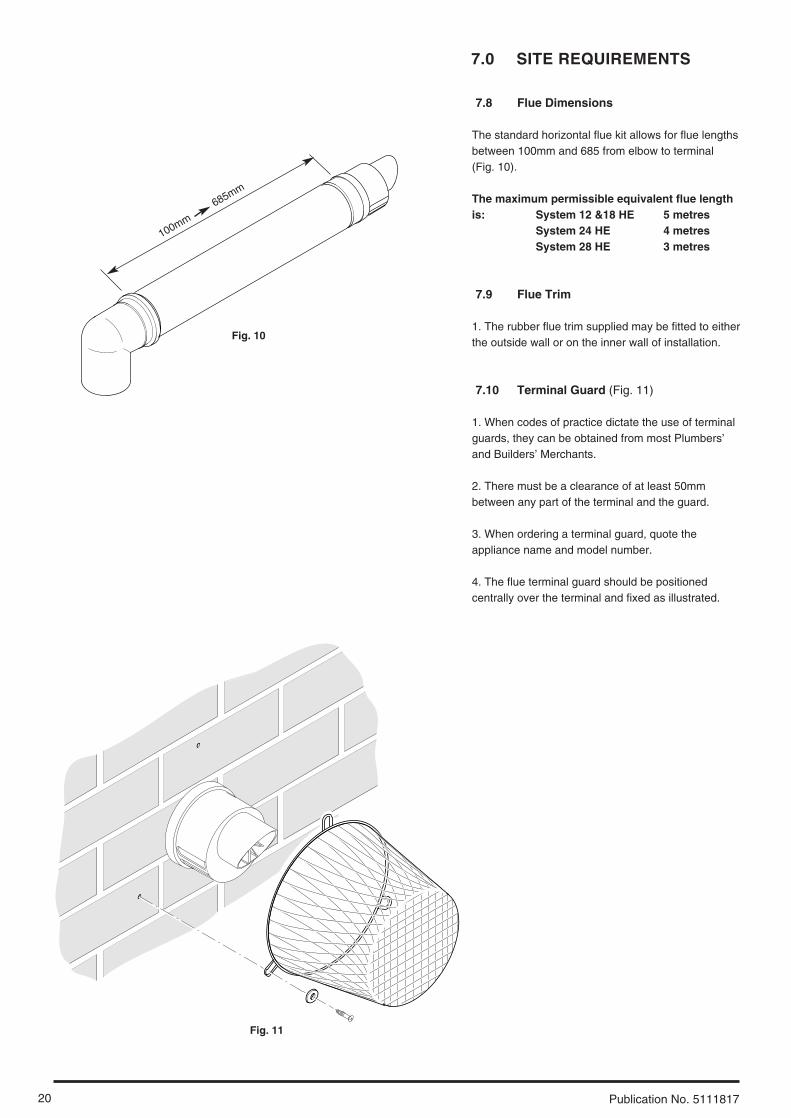
7.8 Flue Dimensions
The standard horizontal flue kit allows for flue lengthsbetween 100mm and 685 from elbow to terminal (Fig. 10).
The maximum permissible equivalent flue lengthis: System 12 &18 HE 5 metres
System 24 HE 4 metresSystem 28 HE 3 metres
7.9 Flue Trim
1. The rubber flue trim supplied may be fitted to eitherthe outside wall or on the inner wall of installation.
7.10 Terminal Guard (Fig. 11)
1. When codes of practice dictate the use of terminalguards, they can be obtained from most Plumbers’and Builders’ Merchants.
2. There must be a clearance of at least 50mmbetween any part of the terminal and the guard.
3. When ordering a terminal guard, quote theappliance name and model number.
4. The flue terminal guard should be positionedcentrally over the terminal and fixed as illustrated.
Fig. 10
Fig. 11
100mm
685mm

21
7.0 SITE REQUIREMENTS
Publication No. 5111817
7.11 Flue Options
1. The Potterton Performa System HE range can befitted with flue systems as illustrated.
2. The standard flue is suitable only for horizontalapplications.
3. Maximum permissible equivalent flue lengthsare:-
12,18 24 28Concentric 5m 4m 3mVertical 5m 4m 3mVertical Twin Pipe 10m 12m 12m
4. Any additional “in line” bends in the flue systemmust be taken into consideration. Their equivalent lengths are:-Concentric Pipes:
45° bend 0.5 metres93° bend 1.0 metres
Twin Flue Pipe45° bend 0.25 metres91.5° bend 0.50 metres
The elbow supplied with the standard horizontal flueis not included in any equivalent length calculations
NOTE: Flue length is measured from point A to Bas shown.
HorizontalFlues
VerticalFlues
VerticalFlues(Twin Pipe)
B
A
B
A
B
A

8.0 INSTALLATION
22 Publication No. 5111817
8.1 Initial Preparation
The gas supply, gas type and pressure must bechecked for suitability before connection (seeSection 7.4).
1. After considering the site requirements (see Section 7.0) position the fixing template on thewall ensuring it is level both horizontally and vertically.
2. Mark the position of the two most suitable fixingslots for the wall plate and boiler lower fixing holes. Itis preferable to use the horizontal fixing slots.
3. Mark the position of the centre of the flue hole (rearexit). For side flue exit, mark as shown (Fig. 12).
4. Note the shaded area on the template. Pipeworkmay be routed upwards behind the boiler, providing itdoes not conflict with the shaded area.
5. If required, mark the position of the gas and waterpipes. Remove the template.
6. Cut the hole for the flue (minimum diameter116mm).
7. Drill the wall as previously marked to accept thewall plugs supplied. Secure the wall plate using thefixing screws.
8. Using a spirit level ensure that the plate is levelbefore finally tightening the screws.
9. Connect the gas and water pipes to the valves onthe wall plate using the copper tails supplied. Ensurethat the sealing washers are fitted between theconnections.
8.2 Flushing
1. Connect a tube to the central heating flow or returnpipe (Fig. 13).
2. Flush thoroughly (see System Details, Section 6.1).
8.3 Preparing The Boiler
1. Remove all packaging.
2. Stand the boiler on its base by using the rear loweredge as a pivot.
NOTE: A small amount of water may drain from theboiler in the upright position.
Fig. 12
Fig. 13
190mm
For Side Flue Exit
Central Heating Return
Flushing Tube
Wall Plate

23
8.0 INSTALLATION
Publication No. 5111817
8.4 Fitting The Boiler
1. Remove the sealing caps from the boilerconnections.
2. Lift the boiler using the lower edges. Engage theslots at the top rear of the boiler on the wall plate (Fig. 14).
3. Insert the sealing washers between the valves andpipes on the wall plate and the boiler connections. Therubber washers must be used on the gasconnection.
4. Tighten all the connections.
8.5 Fitting the Pressure Relief Discharge Pipe (Fig. 15)
1. Remove the discharge pipe from the kit.
2. Determine the routing of the discharge pipe in thevicinity of the boiler. Make up as much of the pipeworkas is practical, including the discharge pipe supplied.
3. The pipework must be at least 15mm diameter andrun continuously downwards to a discharge pointoutside the building. See section 6.6 for further details.
4. Utilising one of the sealing washers, connect thedischarge pipe to the adaptor and tighten the nut.
5. Complete the discharge pipework and route it to theoutside discharge point.
IMPORTANT: Make all soldered joints beforeconnecting to the pressure relief valve.
8.6 Condensate Drain (see section 7.6)
1. Connect the condensate drain using the 1” BSP nutand seal supplied.
Ensure the discharge of condensate complies withany national or local regulations in force (see BritishGas “Guidance Notes for the Installation ofDomestic Gas Condensing Boilers”.
2. The condensate outlet terminates in a 1” BSP nutand seal for the connection of 21.5mm (3/4in) plasticoverflow pipe which should generally dischargeinternally into the household drainage system. If this isnot possible, discharge into an outside drain isacceptable. Fig. 15
Fig. 14
Pressure Relief Valve
Wall Plate
Discharge Pipe

8.0 INSTALLATION
24 Publication No. 5111817
8.7 Fitting The Flue
HORIZONTAL FLUE
1. The standard flue is suitable for lengths between100mm minimum and 685mm maximum, asmeasured from the edge of the flue elbow outlet tothe joint between the terminal and air duct (Fig. 16).
2. Locate the flue elbow on the adaptor at the top ofthe boiler. Set the elbow to the required orientation(Fig. 17).
NOTE: The flue elbow is angled at 93 degrees toensure a fall back to the boiler.
3. Measure the distance from the outside wall face tothe elbow. This dimension will be known as ‘X’ (Fig. 18).
4. To dimension ‘X’ add 50mm. This dimension to beknown as ‘Y’.
IMPORTANT: Check all dimensions beforecutting.
Wall Thickness
(X)
Wall Thickness
(X)
Flue Elbow
Fig. 18
100mm
685mm
Adaptor
Fig. 16
Fig. 17

25
8.0 INSTALLATION
Publication No. 5111817
8.7 Fitting the Flue (Cont)
5. Mark dimension ‘Y’ on the flue as shown (Fig. 19).Carefully cut the waste material from the flue,ensuring that the ducts are square and free fromburrs.
6. The inner flue duct support bracket may be in thewaste portion of the flue. In this case retrieve thebracket before discarding the waste.
7. Take the inner flue support bracket ( if not alreadyfitted) and engage it over the flue duct. This willcentralise the flue and air ducts, and ease assembly(Fig. 20).
8. Insert the flue through the hole in the wall. Fit theelbow to the boiler adaptor, ensuring that it ispushed fully in.
9. Draw the flue back through the wall and engage itin the elbow. It may be necessary to use soapsolution or similar to ease assembly of the elbowadaptor and flue (Fig. 21).
10. Make good between the wall and air duct outsidethe building.
11. Fit the flue trim if required, and if necessary fit aterminal guard (see Section 7.9 & 7.10).
VERTICAL FLUE
1. Only a flue approved with the Potterton PerformaSystem HE range can be used.
2. For information on vertical flues consult thePotterton Flue Guide brochure.
Flue Trim
Inner Flue Support Bracket
Y
Flue
Waste
Flue Elbow
Fig. 19
Fig. 20
Fig. 21

8.0 INSTALLATION
26 Publication No. 5111817
8.8 Making The Electrical Connections
To connect the mains input cable proceed asfollows:-
1. Slacken the facia securing screws and lift theoutercase panel so that its securing tabs are clear ofthe facia. Remove the panel.
2. Completely undo the screws securing the faciapanel and hinge it down (Fig. 22).
3. Remove the control box cover securing screws.Disengage the barbs on the control box from thecover. Remove the cover (Fig. 23).
4. Slacken the cable clamp on the LH side of theboiler chassis (Fig. 24). Insert the cable through theclamp and route it to the terminal block.
5. Slacken the screws in the terminal block, connectthe input cable, and tighten the screws.
6. Run the input cable from any external controlthrough the second cable clamp on the boilerchassis. Refer to the instructions supplied with thecontrol.
7. To connect external control(s) remove the linkbetween terminals 1 & 2. The switched output fromthe external control must be connected to terminal 2(Fig. 25).
IMPORTANT: The external control MUST besuitable for 230V switching and fused 3A maximum
8. Ensure that both mains input and any externalcontrol input cables have sufficient slack to allow thecontrol box to drop down. Tighten the cable clamp(s)on the boiler chassis.
8.9 Preliminary Electrical Checks
1. Prior to commissioning the boiler preliminaryelectrical system checks should be carried out.
2. These should be performed using a suitablemeter, and include checks for Ground Continuity,Resistance to Ground, Short Circuit and Polarity.
Always fit fast blow 2A fuse
230V ~ 50Hzfused 3A maximum
Live (brown)
Neutral (blue)
Earth (green/yellow)
1
2230V S/L from
external control
br
b
g/y
bk
bk
L230 V
Selector / Reset Switch
ExternalControls Nbr b
Pump
Hydraulic Differential Pressure Switchr
r
Safety Overheat Thermostat
Flue Thermostatb
b
Central Heating FlowNTC Sensor
r
r
Gas ValveSpark Electrode
Condensate Trap
Flame Sensing Electrode
Nbr b
Fan
bkbk
bbrbk
Pressure Switchbbr
bk
PCB
b
bbr
r
bk
bk
br
Central Heating ReturnNTC Sensor
g
g
Gas Valve Modulator
Fig. 24
Fig. 23
Fig. 25
Fig. 26
Fig. 22
Terminal Block
Internal Fuse
Cable Clamp
Control Box Cover
Facia Panel
Functional Flow Diagram
Key to Wiringb - bluebr - brownbk - blackr - redg - green

27
9.0 COMMISSIONING
Publication No. 5111817
9.1 Commissioning the Boiler
1. Reference should be made to BS 5449 whencommissioning the boiler.
2. Ensure that the filling loop is connected and open,then open the heating flow and return valves on theboiler.
3. Open the screw on the automatic air vent (Fig. 27).
4. The system must be flushed in accordance withBS 7593 and the flushing agent manufacturersinstructions.
5. Pressurise the system to 1.0 bar then close anddisconnect the filling loop.
6. Turn the gas supply on and purge the systemaccording to in GB BS 6891 and in IE I.S. 813“Domestic Gas Installations”.
7. Test for gas soundness.
8. If at any time during commissioning it is required toterminate a particular cycle, e.g. the pump overrunperiod, turn the selector to the Off position and thenback to the On position ( ) (Fig. 29).
AutomaticAir Vent
PressureGauge
Screw
2
1
0 4
3
bar
Fig. 27
Selector Switch
Central Heating Temperature Control
Fig. 28
2
1
0 4
3
bar
30° 40° 50° 60° 70° 80°
Reset
Pump
Fig. 29
Power OnNeon
9.0 COMMISSIONING
28 Publication No. 5111817
OU
T
MIN
Pressure Test Point Sealing Screw
Fig. 30
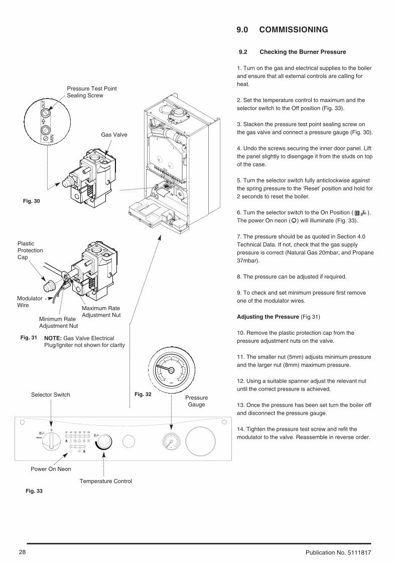
9.2 Checking the Burner Pressure
1. Turn on the gas and electrical supplies to the boilerand ensure that all external controls are calling forheat.
2. Set the temperature control to maximum and theselector switch to the Off position (Fig. 33).
3. Slacken the pressure test point sealing screw onthe gas valve and connect a pressure gauge (Fig. 30).
4. Undo the screws securing the inner door panel. Liftthe panel slightly to disengage it from the studs on topof the case.
5. Turn the selector switch fully anticlockwise againstthe spring pressure to the ‘Reset’ position and hold for2 seconds to reset the boiler.
6. Turn the selector switch to the On Position ( ).The power On neon ( ) will illuminate (Fig. 33).
7. The pressure should be as quoted in Section 4.0Technical Data. If not, check that the gas supplypressure is correct (Natural Gas 20mbar, and Propane37mbar).
8. The pressure can be adjusted if required.
9. To check and set minimum pressure first removeone of the modulator wires.
Adjusting the Pressure (Fig 31)
10. Remove the plastic protection cap from thepressure adjustment nuts on the valve.
11. The smaller nut (5mm) adjusts minimum pressureand the larger nut (8mm) maximum pressure.
12. Using a suitable spanner adjust the relevant nutuntil the correct pressure is achieved.
13. Once the pressure has been set turn the boiler offand disconnect the pressure gauge.
14. Tighten the pressure test screw and refit themodulator to the valve. Reassemble in reverse order.
Selector Switch
Temperature Control
2
1
0 4
3
bar
30° 40° 50° 60° 70° 80°
Reset
Fig. 33
Power On Neon
PressureGauge
2
1
0 4
3
bar
Fig. 32
Gas Valve
Fig. 31
PlasticProtectionCap
ModulatorWire Maximum Rate
Adjustment NutMinimum RateAdjustment Nut
NOTE: Gas Valve ElectricalPlug/Igniter not shown for clarity

29
10.0 COMPLETION
Publication No. 5111817
10.1 Completion
1. Hinge the facia panel upwards and refit the casefront panel. Tighten the securing screws (Fig. 34).
2. Instruct the user in the operation of the boiler andsystem, explaining the operational sequence.
3. Carefully read and complete all sections of theBenchmark Commissioning Checklist at the rear ofthis publication that are relevant to the appliance andinstallation. These details will be required in the eventof any warranty work. The publication must behanded to the user for safe keeping and eachsubsequent regular service visit recorded.
4. For IE, it is necessary to complete a “Declaration ofConformity” to indicate compliance with I.S. 813. Anexample of this is given in I.S. 813 “Domestic GasInstallations”. This is in addition to the BenchmarkCommissioning Checklist.
5. Hand over the Users Operating, Installation andServicing Instructions, giving advice on the necessityof regular servicing.
Fig. 34
Facia Panel
Case Front Panel

11.0 SERVICING
30 Publication No. 5111817
11 .1 Annual Servicing
1. For reasons of safety and economy, it isrecommended that the boiler is serviced annually.Servicing must be performed by a competent person.
2. After servicing, complete the relevant ServiceInterval Record section of the BenchmarkCommissioning Checklist at the rear of thispublication.
3. Ensure that the boiler is cool.
4. Ensure that both the gas and electrical suppliesto the boiler are isolated.
5. Slacken the screws securing the facia panel. Liftthe outercase panel so that its securing tabs are clearof the facia. Remove the panel, allowing the facia tohinge down (Fig. 35).
6. Remove the screws securing the inner door panel.Lift the panel slightly to disengage it from the studs ontop of the case (Fig. 37).
7. Note the positions of the sensing tube(s) (28 HEhas two - one tube on 12/18/24 HE) on the fan spigotand three wires on the fan motor and remove them(Fig. 36).
8. Slacken the screws on the fan spigot outlet pipeclamps. Ease the clamps inwards over the pipe (28HE). On 12/18/24 HE models undo the securingscrew at the left hand end of the pipe and the clampat the right.
9. Draw the outlet pipe away from the boiler.
10. Remove the four screws securing the combustionbox door and remove the door (Fig. 37).
Case Front Panel
Fig. 35
Facia PanelSecuring Screws
Inner DoorPanel
CombustionBox Door
Fan WiresFan
SensingTubes
Ease Fan Spigot OutletPipe Clamps Inwards
Fan Spigot Outlet PipeFig. 36
Fig. 37
28 model
12,18,24model
28 model

31
11.0 SERVICING
Publication No. 5111817
11.1 Annual Servicing (Cont)
12. Ease the front edge of the left hand baffleupwards, disengaging the spring clip. Disengage thetabs on the baffle from the slots in the fan hood (Fig. 38).
13. Undo the screws securing the fan and hood to theappliance back panel. Draw the assembly forwards(Fig. 39).
14. On 28 HE models undo the screws securing theburner to the injector manifold.
15. Draw the burner out of the combustion box,pulling the electrode grommets from the slots in thecombustion box lower panel (Fig. 40).
16. Disconnect the electrode leads and grommetsfrom the electrodes. Completely remove the burner(Fig. 40).
17. Brush any deposits from the injectors. Do not usea pin or wire to clean them.
18. Brush the burner blades and venturis and cleanthe combustion box.
19. Ensure that the heat exchanger fins are clear ofany obstruction.
NOTE: If necessary the secondary heat exchangermay be dismantled - see section 12.23.
20. Check that the pressure vessel charge is 0.5barand reassemble in reverse order of dismantling.
21. Turn the selector switch fully anticlockwiseagainst the spring pressure to position R and hold for2 seconds to reset the boiler before recommissioning.
22. Complete the relevant Service Interval Recordsection of the Benchmark Commissioning Checklist atthe rear of this publication and then hand it back tothe user.
Burner
Electrode
Grommets
Fig. 40
Spring Clip
Fan and HoodAssembly
BaffleTab
Fig. 38
Fig. 39

12.0 CHANGING COMPONENTS
32 Publication No. 5111817
IMPORTANT: When changing componentsensure that both the gas and electrical supplies tothe boiler are isolated before any work is started.When the new component has been fitted turn theselector switch fully anticlockwise against thespring pressure to the ‘Reset’ position and hold for2 seconds to reset the boiler beforerecommissioning.
See Section 11.1 “Annual Servicing” for removal ofcase panel, door etc.
12.1 Fan (Figs. 42 & 43)
1. Note the positions of the sensing tube(s) (28 HEhas two - one tube on 12/18/24 HE) on the fanspigot and three wires on the fan motor and removethem.
2. Slacken the screws on the fan spigot outlet pipeclamps. Ease the clamps inwards over the pipe (28HE). On 12/18/24 HE models undo the securingscrew at the left hand end of the pipe and the clampat the right.
3. Draw the outlet pipe away from the boiler.
4. Remove the four screws securing the combustionbox door and remove the door.
5. Ease the front edge of the left hand baffleupwards, disengaging the spring clip. Disengage thetabs on the baffle from the slots in the fan hood.
6. Undo the screws securing the fan hood to theappliance back panel, and draw the fan and hoodassembly forwards.
7. Remove the screws and spring washers securingthe fan to the hood.
8. Fit the new fan to the hood using the screws andspring washers previously removed.
9. Reassemble in reverse order of dismantling.
12.2 Pressure Switch (Fig. 41)
1. Remove the fan as described in section 12.1.
2. Note the positions of the two sensing tubes andthree wires and remove them.
3. Remove the two screws holding the pressureswitch to the bracket on the combustion box toppanel.
4. Fit the new pressure switch and reassemble allcomponents in reverse order of dismantling.
PressureSwitch
SensingTubes
Pressure Switch Wires
Fig. 41
Fan Hood
Spring Washer
Securing Screw
Fan WiresFan
SensingTubes
Ease Fan Spigot OutletPipe Clamps Inwards
Fan Spigot Outlet Pipe
Spring Clip
BaffleTab
Fan
Fig. 42
Fig. 43
28 model
12,18,24model
33
12.0 CHANGING COMPONENTS
Publication No. 5111817
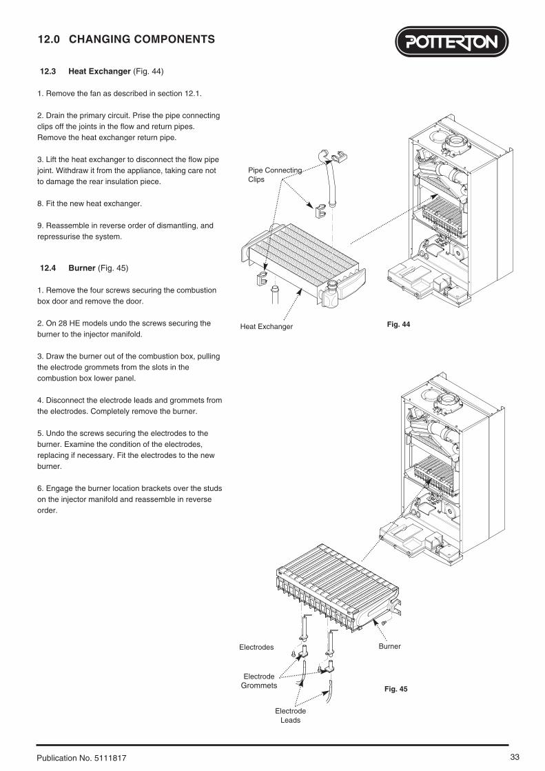
12.3 Heat Exchanger (Fig. 44)
1. Remove the fan as described in section 12.1.
2. Drain the primary circuit. Prise the pipe connectingclips off the joints in the flow and return pipes.Remove the heat exchanger return pipe.
3. Lift the heat exchanger to disconnect the flow pipejoint. Withdraw it from the appliance, taking care notto damage the rear insulation piece.
8. Fit the new heat exchanger.
9. Reassemble in reverse order of dismantling, andrepressurise the system.
12.4 Burner (Fig. 45)
1. Remove the four screws securing the combustionbox door and remove the door.
2. On 28 HE models undo the screws securing theburner to the injector manifold.
3. Draw the burner out of the combustion box, pullingthe electrode grommets from the slots in thecombustion box lower panel.
4. Disconnect the electrode leads and grommets fromthe electrodes. Completely remove the burner.
5. Undo the screws securing the electrodes to theburner. Examine the condition of the electrodes,replacing if necessary. Fit the electrodes to the newburner.
6. Engage the burner location brackets over the studson the injector manifold and reassemble in reverseorder.
Burner
ElectrodeGrommets
Electrode Leads
Electrodes
Fig. 44Heat Exchanger
Pipe ConnectingClips
Fig. 45

12.0 CHANGING COMPONENTS
34 Publication No. 5111817
12.5 Injectors (Fig. 46)
1. Remove the burner as described in Section 12.4.
2. Undo the screws securing the injector manifold tothe inlet elbow and remove the manifold.
3. Unscrew and replace injectors as required andexamine the sealing gasket, replacing as necessary.Reassemble in reverse order.
12.6 Electrodes (Fig. 46)
1. Remove the four screws securing the combustionbox door and remove the door.
2. Undo the screws securing the burner to the injectormanifold. Draw the burner out of the combustion box,pulling the electrode grommets from the slots in thecombustion box lower panel.
3. Disconnect the lead and grommet from theelectrode being replaced. Undo the securing screwand withdraw the electrode to the burner.
4. Reassemble in reverse order.
12.7 Insulation (Fig. 47)
1. Remove the four screws securing the combustionbox door and remove the door.
2. Slide the side insulation pieces carefully out of theircarriers.
3. To replace the rear insulation piece it is necessaryto remove the heat exchanger as described in Section12.3 and slide out the side pieces.
4. The combustion box door insulation piece can bereplaced by carefully bending up the two retainingtabs.
5. Replace all insulation pieces and reassemble inreverse order.
13.8
InjectorManifold
Inlet Elbow
Gasket
Injector
Burner
ElectrodeGrommets
Electrode Leads
Side Insulation
Rear Insulation
Front Insulation
CombustionBox Door
Side Insulation
Electrodes
Fig. 46
Fig. 47
28 model

35
12.0 CHANGING COMPONENTS
Publication No. 5111817
12.8 Gas Valve (Fig. 48)
1. Undo the nut on the gas feed pipe under the boiler.
2. Completely undo the securing screws and hingethe facia panel down.
3. Disconnect the wires from the valve modulator andthe ignition lead from the spark generator.Disconnect the pressure sensing pipe from the valve.Undo the screw securing the spark generatorelectrical plug to the valve and disconnect the plug.
4. Pull the earth wire off the spade terminal on thevalve.
5. Remove the screws securing the inlet pipe flangeto the boiler bottom panel and those securing theoutlet manifold to the burner manifold.
6. Remove the valve from the boiler.
7. Note the orientation of the inlet pipe and outletmanifold. Undo the securing screws and remove thepipe and manifold.
8. Examine the ‘O’ ring seals for damage, replacingas necessary.
9. Fit the inlet pipe and outlet manifold to the newvalve, ensuring that the ‘O’ ring seals are in place.
10. Reassemble in reverse order and check theburner pressure as described in Section 9.2.
12.9 Central Heating Temperature Sensor (Fig. 49)
1. Ease the retaining tab on the sensor away anddisconnect the electrical plug.
2. Unscrew the sensor from it’s pocket andreassemble in reverse order. The plug will only fit oneway.
12.10 Safety Thermostat (Fig. 49)
1. Pull the electrical connections off the thermostat.
2. Remove the screws securing the thermostat to themounting plate on the flow pipe.
3. Reassemble in reverse order. The thermostat isnot polarised - either wire can fit either terminal onthe thermostat.
12.11 Return Heating Temperature Sensor (Fig. 50)
1. Ease the retaining tab on the sensor away and disconnect the electrical plug.
2. Prise the sensor retaining clip off the pipe andremove the sensor from the clip.
3. Reassemble in reverse order.
Gas Valve
Inlet Pipe
Gas FeedPipe
ElectricalPlug
Central HeatingTemperature Sensor
SafetyThermostat
Return HeatingTemperature Sensor
Retaining Clip
Heating Return Pipe
Flow Pipe
Fig. 48
Fig. 49
Fig. 50
ModulatorWires
IgnitionLead

12.0 CHANGING COMPONENTS
36 Publication No. 5111817
12.12 Pump - Head Only (Fig. 51)
1. Drain the primary circuit and remove the sockethead screws securing the pump head to the bodyand draw the head away.
2. Undo the screw on the pump wiring cover andremove the cover. Using a suitable flat bladed screwdriver press the cable securing levers downwards torelease each wire after noting their position.
3. A standard replacement Grundfos 15-60 head cannow be fitted. Connect the pump wiring to the newhead. The pump speed must be set to 3 (Fig. 52).
4. Reassemble in reverse order.
12.13 Pump - Complete (Fig. 53)
1. Drain the primary circuit and unscrew theautomatic air vent from the pump body. Undo thetwo screws securing the body to the pipe andmanifold and draw the pump forwards.
2. Undo the screw on the pump wiring cover andremove the cover. Using a suitable flat bladed screwdriver press the cable securing levers downwards torelease each wire after noting their position.
3. Connect the wiring to the new pump. Examine the‘O’ ring seals on the return pipe and manifold,replacing if necessary.
4. Fit the air vent to the pump body and reassemblein reverse order.
12.14 Automatic Air Vent (Fig. 53)
1. Drain the primary circuit and unscrew theautomatic air vent from the pump body.
2. Examine the ‘O’ ring seal, replacing if necessary,and fit it to the new automatic air vent.
3. Reassemble in reverse order.
Pump Setting
Pump WiringCover
Socket HeadedScrew
Pump Head
Pump Body
Pump WiringCover
AutomaticAir Vent
Fig. 51
Fig. 53
Fig. 52

37
12.0 CHANGING COMPONENTS
Publication No. 5111817
12.15 Pressure Gauge (Figs. 54 & 55)
1. Drain the primary circuit and undo the nut on thepressure gauge capillary.
2. Remove the timer cover and ease the timer wiringaside. Undo the screws securing the gauge retainingbracket.
3. Remove the bracket and gauge assembly.Depress the barbs on the side of the gauge andremove the retaining bracket.
4. Reassemble in reverse order.
12.16 Expansion Vessel (Fig. 56)
1. To replace the expansion vessel it is necessary toremove the boiler from the wall.
NOTE: Alternatively a vessel of equivalentcapacity can be fitted on the system return pipeas close as possible to the boiler.
2. Drain the system and undo all gas, water andcondensate drain connections. Remove the flueelbow.
3. Lift the boiler off the wall plate and lay it on eitherside on a clean flat surface.
4. Undo the nut on the vessel outlet spigot, andremove the locknut and spring washer securing thespigot to the boiler chassis.
5. Undo the screws and remove the appliance uppercross member. Slide the expansion vessel out of theretaining clips.
6. Reassemble in reverse order. Fully recommissionthe appliance and system.
12.17 Condensate Trap (Fig. 57)
1. Disconnect the two sensing wires from the trapconnections.
2. Squeeze together the wire spring clip to releaseand ease the inlet pipe from the trap spigot.
3. Undo the nut securing the condensate drain pipeto the trap. Disconnect the pipe and sealing washer.
4. From underneath the boiler remove the screwssecuring the trap bracket.
5. Remove the trap and bracket from the boiler.Undo the locknut securing the trap to the bracket.
6. Reassemble in reverse order.
Pressure Gauge
Timer Cover
Pressure GaugeCapillary
Gauge RetainingBracket
Expansion Vessel
Retaining Clip
Vessel OutletSpigot
BoilerChassis
Lock Nut SpringWasher
Fig. 54
Fig. 55
Fig. 56
Upper CrossMember
Inlet PipeSensing Wires
CondensateTrap
Wire SpringClip
Bracket
CondensateDrain Pipe
Fig. 57
12.0 CHANGING COMPONENTS
38 Publication No. 5111817
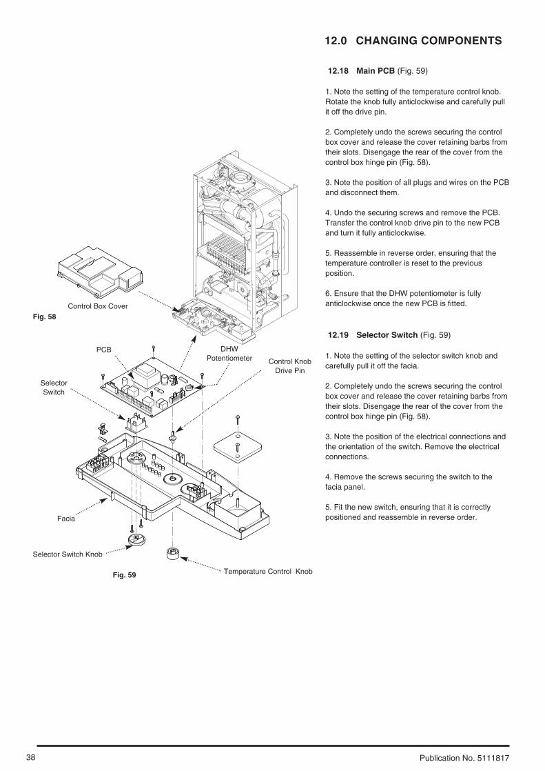
12.18 Main PCB (Fig. 59)
1. Note the setting of the temperature control knob.Rotate the knob fully anticlockwise and carefully pullit off the drive pin.
2. Completely undo the screws securing the controlbox cover and release the cover retaining barbs fromtheir slots. Disengage the rear of the cover from thecontrol box hinge pin (Fig. 58).
3. Note the position of all plugs and wires on the PCBand disconnect them.
4. Undo the securing screws and remove the PCB.Transfer the control knob drive pin to the new PCBand turn it fully anticlockwise.
5. Reassemble in reverse order, ensuring that thetemperature controller is reset to the previousposition.
6. Ensure that the DHW potentiometer is fullyanticlockwise once the new PCB is fitted.
12.19 Selector Switch (Fig. 59)
1. Note the setting of the selector switch knob andcarefully pull it off the facia.
2. Completely undo the screws securing the controlbox cover and release the cover retaining barbs fromtheir slots. Disengage the rear of the cover from thecontrol box hinge pin (Fig. 58).
3. Note the position of the electrical connections andthe orientation of the switch. Remove the electricalconnections.
4. Remove the screws securing the switch to thefacia panel.
5. Fit the new switch, ensuring that it is correctlypositioned and reassemble in reverse order.
Control Box Cover
PCB
SelectorSwitch
Facia
Selector Switch Knob
Temperature Control Knob
Fig. 58
Fig. 59
Control KnobDrive Pin
DHWPotentiometer

39
12.0 CHANGING COMPONENTS
Publication No. 5111817
12.20 Central Heating Differential Valve (Figs. 60 & 61)
1. Drain the primary circuit.
2. Undo the screw securing the microswitch to thedifferential valve. Allow the microswitch to rest to oneside.
3. Undo the pressure gauge capillary nut and heatingflow pipe nut from the valve.
4. Prise off the bypass connecting clips anddisconnect the heating flow tap. Undo the screwssecuring the valve to the boiler bottom panel.Remove the valve.
5. Remove the screws securing the cover from thevalve body. Examine the condition of the diaphragm,spring and pushrod, replacing as necessary.
6. If required the complete valve assembly can bereplaced.
7. Examine the sealing washers and ‘O’ ring on thepipes and capillary, replacing as necessary.
12.21 Central Heating Differential ValveMicroswitch (Fig. 61)
1. Remove the two wires from the microswitch.
2. Undo the screw securing the microswitch to thevalve body.
3. Reassemble in reverse order.
12.22 Pressure Relief Valve (Fig. 62)
1. Drain the primary circuit.
2. Disconnect the discharge pipe from the valve.Using a suitable hexagon key undo the grub screwsufficiently to release the valve.
3. Note the orientation of the valve, rotate it andwithdraw it from the manifold.
4. Fit the new valve and ‘O’ ring seal and set to thepreviously noted orientation. Reassemble in reverseorder.
MicroswitchBracket
Diaphragm
Fig. 60
Fig. 61
Pressure Relief Valve
Grub Screw
‘O’ ring seal
Discharge Pipe
Fig. 62

12.0 CHANGING COMPONENTS
40 Publication No. 5111817
12.23 Secondary Heat Exchanger) (Fig. 63)
1. Drain the primary circuit
2. Undo the four screws securing the right hand casepanel. Remove the panel.
3. Prise the connecting clips from the heat exchangerreturn pipe and the boiler return pipe. Remove thepipes.
4. Slacken the screws on the left hand fan spigotoutlet pipe clamp. Ease the clamp to the right.
5. Remove the nut securing the elbow to thesecondary heat exchanger. Draw the elbow and outletpipe forwards.
6. Remove the secondary heat exchanger from theouter drum by easing it forward.
7. Reassemble in reverse order of dismantling.
12.24 Flue Overheat Thermostat (Fig. 64)
NOTE: The flue overheat thermostat includes areset button. Check that the thermostat will notreset before replacing.
1. Remove the fan spigot outlet pipe from the fan andelbow.
2. Pull the two wires off the terminals on the flueoverheat thermostat. Unscrew the thermostat from theadaptor in the outlet elbow.
3. Reassemble in reverse order of dismantling.
Ease Fan Spigot OutletPipe Clamps Inwards
Fan Spigot Outlet Pipe
Overheat Thermostat
Fan Spigot OutletPipe Clamp
Fan SpigotOutlet Pipe
Secondary Heat Exchanger
Outer Drum
Boiler Return Pipe
Pipe Connecting Clip
ElbowHeat ExchangerReturn Pipe
Fig. 63
Fig. 64
28 model
12,18,24model
41
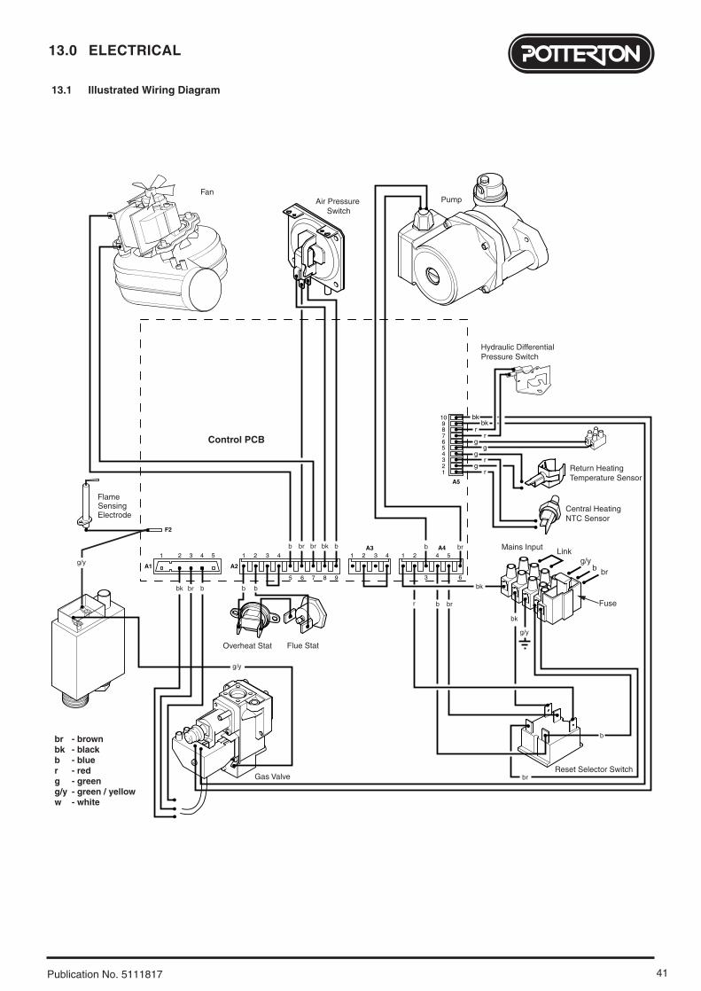
13.0 ELECTRICAL
Publication No. 5111817
- brown- black- blue- red
brbkbr
- green- green / yellow- white
gg/yw
Return Heating Temperature Sensor
Reset Selector Switch
Control PCB
A1 A2
A3 A4
A5
F2
1
bkbk
rr
gg
21 2 33 4 1
123456789
10
2 3 4 1 2
3 6
4 54
5
5
6 7 8 9
Central Heating NTC Sensor
Fan
Gas Valve
Overheat Stat
Hydraulic Differential Pressure Switch
Air Pressure Switch
Flame
Mains Input
Fuse
Link
g/y
g/yb br
bk
br
b
bk
rg
rg
SensingElectrode
Pump
bb
bbbk b
br
br
b
br
bkbrbr
Flue Stat
br
g/y
g/y
13.1 Illustrated Wiring Diagram

14.0 SHORT PARTS LIST
42 Publication No. 5111817
Key G.C. Description ManufacturersNo. No. Part No.
22 Fan (12,18 HE) 5113278
Fan (24 HE) 5112627
Fan (28 HE) 5112430
23 Pressure Switch (12 HE) 5113279
Pressure Switch (18 HE) 5113280
Pressure Switch (24,28 HE) 248466
32 Heat Exchanger (12,18 HE) 5113284
Heat Exchanger (24,28 HE) 5112431
41 Burner (12 HE) 5113285
Burner (18 HE) 5113286
Burner (24,28 HE) 5112770
44 Injector 1.18 (12,18,24 HE) 247439
Injector 1.25 (28 HE) 5112376
59 E66 408 Electrode Lead 248037
63 E66 411 Spark or Sensing
Electrode 247384
72 E66 539 Pump 248042
102 Hydraulic Outlet Assy 248490
131 342 571 Temperature Sensor 247394
135 E66 439 Safety Thermostat 248079
140 Gas Valve 5107339
154 PCB 5112380
169 E66 453 Pressure Gauge 248090
528 Return Heating 248497
Temperature Sensor
371 Igniter/Gas Valve
Cable 5112385
A Flue Overheat
Thermostat 5112395
22 14044
63
102
72
135
59
41
154
169
131528
23
32
A
371

43
15.0 FAULT FINDING
Publication No. 5111817
Carry out initial fault finding checks1. Check that gas, water and electrical supplies are available at the boiler. Electrical supply = 230V ~ 50 Hz.
CH water system pressurised to 0.5 bar when the boiler is cold. The preferred minimum gas pressure is 19.5mbar (natural gas),or 36mbar (propane).
2. Carry out electrical system checks, i.e. Ground Continuity, Resistance to Ground, Short Circuit and Polarity with a suitable meter. NOTE: These checks must be repeated after any servicing or fault finding.
3. Ensure all external controls are calling for heat and check all external and internal fuses. Before any servicing or replacement of parts ensure the gas and electrical supplies are isolated.
Refer to Section 13.0 “Illustrated Wiring Diagram” for position of numbered terminalsCentral Heating - Follow operational sequence
Turn selector to neon illuminated
Primary flow switchoperated
Fan runs at max speed
Burner goes out
Turn temperature controlto max.
Pump runs
Air pressure switch proved
neon flashing
Burner on neonilluminated
Burner output modulates until set
temperature is reached
Spark at ignitionelectrodes for up to 10
seconds
Go to section ‘A’
neon flashingGo to section ‘B’
neon flashingGo to section ‘C’
Go to section ‘J’
neons flashingGo to section ‘D’
neon flashingGo to section ‘E’
Replace PCB
Turn selector to the resetposition. If the neon does
not extinguish go tosections ‘H’ & ‘K’
Go to section ‘F’
neon flashingGo to section ‘I’
Go to section ‘G’
Fan stops Pump stopsOperation sequence
correct
neon flashing
Turn selector to resetposition. If regular
resetting is required orappliance still does notoperate investigation is
necessary
External controls callingfor heat
Ensure controls are set todemand and verify the
contacts are closed
Burner extinguishes after 10 seconds
YES
YES
YES
YES
YES
YES
YES
YES
YES
YES
NO
YES
YES YES YES
NO
NO NO
NO
NO
NO
NO
NO
NO
NO
YES
NO
NOTE: When instructed to turn theselector to the reset position turn theselector switch fully anticlockwiseagainst the spring pressure to the‘Reset’ position and hold for 2seconds to reset the boiler.

15.0 FAULT FINDING
44 Publication No. 5111817
Fault Finding Solutions Sections A to E
Is there 230V at:
Is there 230V at:
Main terminals L and N Check electrical supply1. NO
Main terminal fuse Replace fuseReplace PCBneon
illuminated
2. YES
Selector terminals a & band a & 3. PCB - A4connector terminals 4 & 5
Check wiringReplace selector
3. NO
NO
A
Pump Replace pump1. YES
PCB - A4 connector terminals 3 & 6 Replace PCB2. NO
Change pump supply cable
YES
B
CH system pressure 0.5 to 1.5 bar Re-pressurise system1. NO
Primary flow valve diaphragm damaged Replace diaphragm
Flow valve rod obstructed
3. YES
Check the tap of the automaticair vent is opened
Open the automatic air vent2. NO
NO
C
YES
Continuity across flowmicroswitch and PCB - A5connector terminals 7 & 8
Replace microswitch1.
NO
NO
Flow or Return temperature sensor faulty. Cold resistance approx. 11K ohms (resistance reduces with increase in temp.)
Replace sensor2.
YESFan connections correct at fan.PCB - A2 connector, is 230Vacross terminals 5 & 7
Fan jammed or faulty winding
Replace PCB
Replace fanYES
3.
D
If pump jammed, release
Check and correct if necessary1. Electrical and pressure tube connections2. Blockage of pressure tubes3. Restriction in flue4. Venturi
NO
EReplace airpressure switch
Gas at burner Ensure gas is on and purged
Replace PCB
Replace gas valve
neon flashing
PCB - A1 connector has 230V ACacross terminals 2 & 4
YES
Turn selector switchto Reset position
YES
NO
NO
NO
F
NO
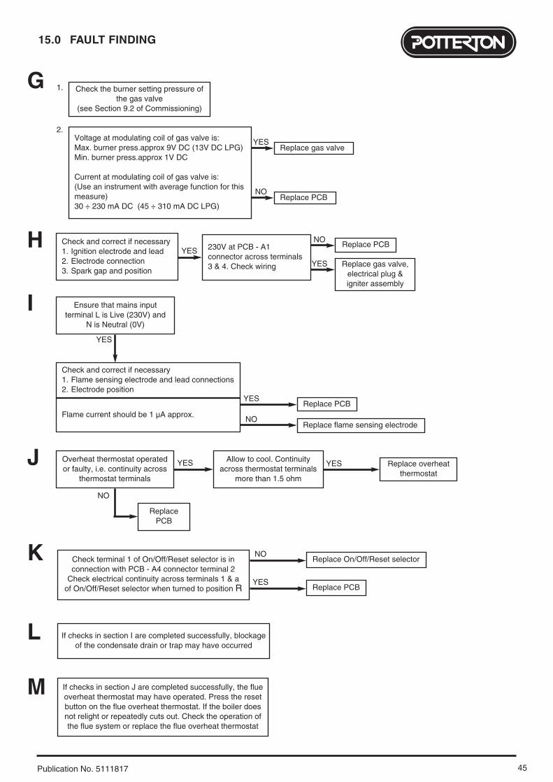
45
15.0 FAULT FINDING
Publication No. 5111817
Replace PCB
G
Check and correct if necessary1. Ignition electrode and lead2. Electrode connection3. Spark gap and position
230V at PCB - A1connector across terminals 3 & 4. Check wiring
YESNO
Replace gas valve,electrical plug &igniter assembly
YES
H
YES
Check the burner setting pressure ofthe gas valve
(see Section 9.2 of Commissioning)
1.
Voltage at modulating coil of gas valve is:Max. burner press.approx 9V DC (13V DC LPG)Min. burner press.approx 1V DC
Current at modulating coil of gas valve is:(Use an instrument with average function for thismeasure)30 ÷ 230 mA DC (45 ÷ 310 mA DC LPG)
Replace gas valve
NOReplace PCB
2.
Check and correct if necessary1. Flame sensing electrode and lead connections2. Electrode position
Flame current should be 1 µA approx.Replace PCB
ReplacePCB
NO
YES
Replace flame sensing electrodeNO
YES
Ensure that mains inputterminal L is Live (230V) and
N is Neutral (0V)
I
Check terminal 1 of On/Off/Reset selector is inconnection with PCB - A4 connector terminal 2
Check electrical continuity across terminals 1 & aof On/Off/Reset selector when turned to position R
Replace On/Off/Reset selectorNO
Replace PCBYES
K
Replace overheatthermostat
YESYESOverheat thermostat operatedor faulty, i.e. continuity across
thermostat terminals
Allow to cool. Continuityacross thermostat terminals
more than 1.5 ohm
J
If checks in section I are completed successfully, blockageof the condensate drain or trap may have occurred
L
If checks in section J are completed successfully, the flueoverheat thermostat may have operated. Press the resetbutton on the flue overheat thermostat. If the boiler doesnot relight or repeatedly cuts out. Check the operation ofthe flue system or replace the flue overheat thermostat
M

CONTROLS To comply with the Building Regulations, each section must have a tick in one or other of the boxes
TIME & TEMPERATURE CONTROL TO HEATING ROOM T/STAT & PROGRAMMER/TIMER PROGRAMMABLE ROOMSTAT
TIME & TEMPERATURE CONTROL TO HOT WATER CYLINDER T/STAT & PROGRAMMER/TIMER COMBI BOILER
HEATING ZONE VALVES FITTED NOT REQUIRED
HOT WATER ZONE VALVES FITTED NOT REQUIRED
THERMOSTATIC RADIATOR VALVES FITTED
AUTOMATIC BYPASS TO SYSTEM FITTED NOT REQUIRED
FOR ALL BOILERS CONFIRM THE FOLLOWING
THE SYSTEM HAS BEEN FLUSHED IN ACCORDANCE WITH THE BOILER MANUFACTURER’S INSTRUCTIONS?
THE SYSTEM CLEANER USED
THE INHIBITOR USED
FOR THE CENTRAL HEATING MODE, MEASURE & RECORD
GAS RATE ft3/hr
BURNER OPERATING PRESSURE (IF APPLICABLE) mbar
CENTRAL HEATING FLOW TEMPERATURE °C
CENTRAL HEATING RETURN TEMPERATURE °C
FOR COMBINATION BOILERS ONLY
HAS A WATER SCALE REDUCER BEEN FITTED? YES NO
WHAT TYPE OF SCALE REDUCER HAS BEEN FITTED?
FOR THE DOMESTIC HOT WATER MODE, MEASURE & RECORD
GAS RATE ft3/hr
MAXIMUM BURNER OPERATING PRESSURE (IF APPLICABLE) mbar
COLD WATER INLET TEMPERATURE °C
HOT WATER OUTLET TEMPERATURE °C
WATER FLOW RATE lts/min
FOR CONDENSING BOILERS ONLY CONFIRM THE FOLLOWING
THE CONDENSATE DRAIN HAS BEEN INSTALLED IN ACCORDANCE WITH THE MANUFACTURER’S INSTRUCTIONS? YES
FOR ALL INSTALLATIONS CONFIRM THE FOLLOWING
THE HEATING AND HOT WATER SYSTEM COMPLIES WITH CURRENT BUILDING REGULATIONS
THE APPLIANCE AND ASSOCIATED EQUIPMENT HAS BEEN INSTALLED AND COMMISSIONEDIN ACCORDANCE WITH THE MANUFACTURER’S INSTRUCTIONS
IF REQUIRED BY THE MANUFACTURER, HAVE YOU RECORDED A CO/CO2 RATIO READING? N/A YES CO/CO2 RATIO
THE OPERATION OF THE APPLIANCE AND SYSTEM CONTROLS HAVE BEEN DEMONSTRATED TO THE CUSTOMER
THE MANUFACTURER’S LITERATURE HAS BEEN LEFT WITH THE CUSTOMER
m3/hr
m3/hr
COMMISSIONING ENG’S NAME PRINT CORGI ID No.
SIGN DATE
BOILER SERIAL No. NOTIFICATION No.
BENCHMARK No.
GAS BOILER COMMISSIONING CHECKLISTC O L L E C T I V E M A R K
N/A
N/A
5 1 1 1 8 1 7
46

SERVICE 1 DATE
ENGINEER NAME
COMPANY NAME
TEL No.
CORGI ID CARD SERIAL No.
COMMENTS
SIGNATURE
SERVICE 2 DATE
ENGINEER NAME
COMPANY NAME
TEL No.
CORGI ID CARD SERIAL No.
COMMENTS
SIGNATURE
SERVICE 3 DATE
ENGINEER NAME
COMPANY NAME
TEL No.
CORGI ID CARD SERIAL No.
COMMENTS
SIGNATURE
SERVICE 4 DATE
ENGINEER NAME
COMPANY NAME
TEL No.
CORGI ID CARD SERIAL No.
COMMENTS
SIGNATURE
SERVICE 5 DATE
ENGINEER NAME
COMPANY NAME
TEL No.
CORGI ID CARD SERIAL No.
COMMENTS
SIGNATURE
SERVICE 6 DATE
ENGINEER NAME
COMPANY NAME
TEL No.
CORGI ID CARD SERIAL No.
COMMENTS
SIGNATURE
SERVICE 7 DATE
ENGINEER NAME
COMPANY NAME
TEL No.
CORGI ID CARD SERIAL No.
COMMENTS
SIGNATURE
SERVICE 8 DATE
ENGINEER NAME
COMPANY NAME
TEL No.
CORGI ID CARD SERIAL No.
COMMENTS
SIGNATURE
SERVICE 9 DATE
ENGINEER NAME
COMPANY NAME
TEL No.
CORGI ID CARD SERIAL No.
COMMENTS
SIGNATURE
SERVICE 10 DATE
ENGINEER NAME
COMPANY NAME
TEL No.
CORGI ID CARD SERIAL No.
COMMENTS
SIGNATURE
SERVICE INTERVAL RECORDIt is recommended that your heating system is serviced regularly
and that you complete the appropriate Service Interval Record Below.
Service Provider. Before completing the appropriate Service Interval Record below, please ensure you have carried out the service
as described in the boiler manufacturer’s instructions. Always use the manufacturer’s specified spare part when replacing all controls
47
Publication No. 5111817 - Iss. 3 (04/2005)
All descriptions and illustrations provided in this leaflet have been
carefully prepared but we reserve the right to make changes and
improvements in our products which may affect the accuracy of the
information contained in this leaflet. All goods are sold subject to
our standard Conditions of Sale which are available on request.
General Enquiries (GB)
Tel. 08706 060 780Technical (GB)
Tel. 08706 049 049Service (GB)
Tel. 08706 096 096Fax. 01926 410 006
Literature Request (GB)
Tel. 08706 060 623
Technical (IE)
Tel. 1850 560570
BAXI POTTERTONA Trading Division of Baxi Heating UK LtdBrownedge Road Bamber Bridge Preston Lancashire PR5 6UPAfter Sales Service 08706 096 096 Technical Enquiries 08706 049 049Website www.potterton.co.uk
company923.690.2

User’s Guide PerformaSystem HE
This is a Wall Mounted Powered Flue Condensing Boiler Gas Fired Central Heating Unit.
The boiler meets the requirements of Statutory Instrument “ The Boiler (Efficiency) Regulations 1993 No 3083” and isdeemed to meet the requirements of Directive 92/42/EEC on the energy efficiency requirements for new hot waterboilers fired with liquid or gaseous fuels:-
Type test for purpose of Regulation 5 certified by: Notified Body 0051.
Product/Production certified by:Notified Body 0051.
For use in GB/IE only.

2 Publication No. 5111818
Natural Gas
Potterton Performa System 12 HEG.C.No 41 591 24Potterton Performa System 18 HEG.C.No 41 591 25Potterton Performa System 24 HEG.C.No 41 591 26Potterton Performa System 28 HEG.C.No 41 591 27
IMPORTANT - Installation, Commissioning, Service & Repair
This appliance must be installed in accordance with themanufacturer’s instructions and the regulations in force. Readthe instructions fully before installing or using the appliance.
In GB, this must be carried out by a competent person asstated in the Gas Safety (Installation & Use) Regulations.
Definition of competence: A person who works for a CORGIregistered company and holding current certificates in therelevant ACS modules, is deemed competent.
In IE, this must be carried out by a competent person asstated in I.S. 813 “Domestic Gas Installations”.
Lifting - This product should be lifted and handled by twopeople. Stooping should be avoided and protective equipmentworn where necessary. Carrying & lifting equipment should beused as required, e.g. when installing in a loft space.
The addition of anything that may interfere with the normaloperation of the appliance without express written permissionfrom the manufacturer or his agent could invalidate theappliance warranty. In GB this could also infringe the GasSafety (Installation and Use) Regulations.
Warning - Check the information on the data plate iscompatible with local supply conditions.
Benchmark Commissioning Checklist
Please ensure that your installer hands you the boilerInstallation & Service Instructions with the BenchmarkCommissioning Checklist sections completed. The details inthe Checklist will be required in the event of any warrantywork. Keep the instructions in a safe place and ensure that theService Interval Record at the back is completed at eachservice visit.
CORGI
All CORGI registered installers carry a CORGI identificationcard and have a registration number. You can check yourinstaller is registered by telephoning 0870 4012300 or writingto:-
1 Elmwood,Chineham Business Park,
Crockford Lane,Basingstoke. RG24 8WG
or check online at www.corgi-gas-safety.com
This product has an energy rating (B) on a scale of A to G.For more information see www.boilers.org.uk. This is a certification mark.
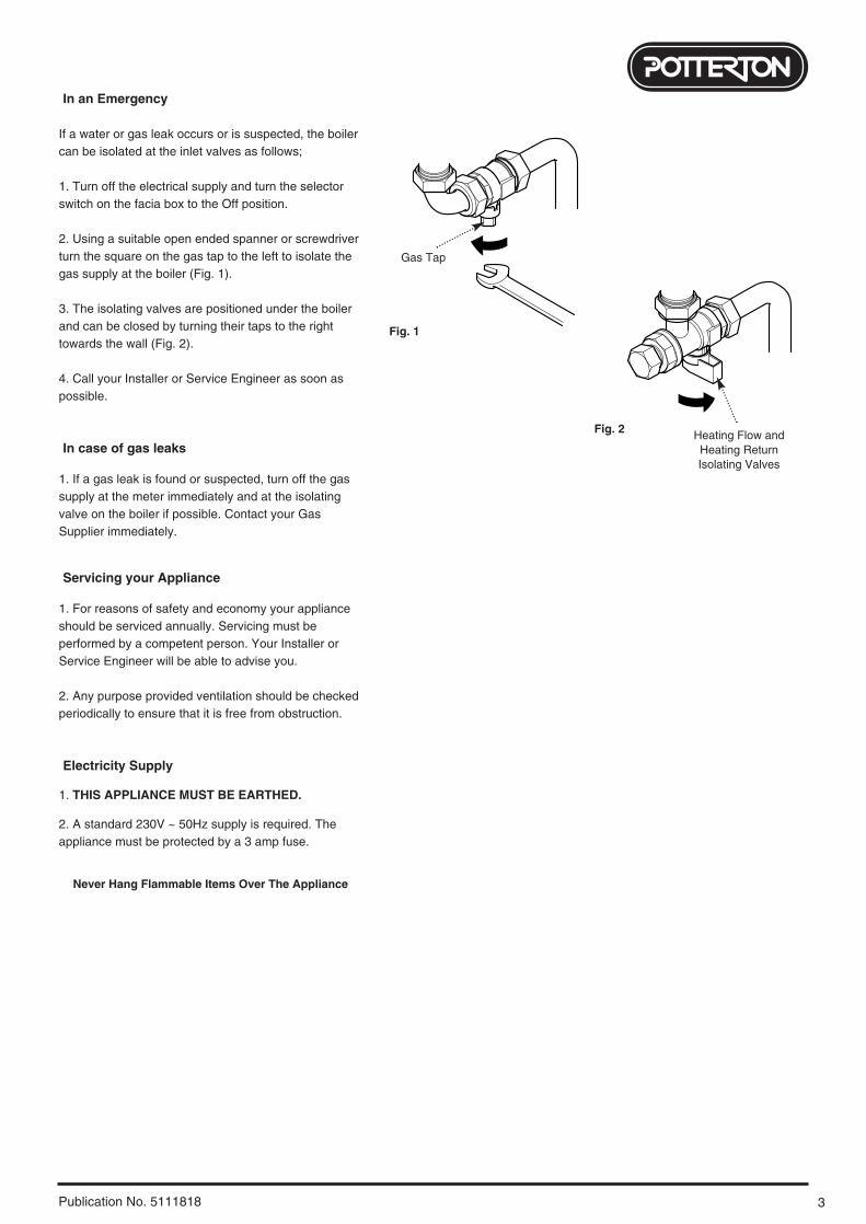
3Publication No. 5111818
In an Emergency
If a water or gas leak occurs or is suspected, the boilercan be isolated at the inlet valves as follows;
1. Turn off the electrical supply and turn the selectorswitch on the facia box to the Off position.
2. Using a suitable open ended spanner or screwdriverturn the square on the gas tap to the left to isolate thegas supply at the boiler (Fig. 1).
3. The isolating valves are positioned under the boilerand can be closed by turning their taps to the righttowards the wall (Fig. 2).
4. Call your Installer or Service Engineer as soon aspossible.
In case of gas leaks
1. If a gas leak is found or suspected, turn off the gassupply at the meter immediately and at the isolatingvalve on the boiler if possible. Contact your GasSupplier immediately.
Servicing your Appliance
1. For reasons of safety and economy your applianceshould be serviced annually. Servicing must beperformed by a competent person. Your Installer orService Engineer will be able to advise you.
2. Any purpose provided ventilation should be checkedperiodically to ensure that it is free from obstruction.
Electricity Supply
1. THIS APPLIANCE MUST BE EARTHED.
2. A standard 230V ~ 50Hz supply is required. Theappliance must be protected by a 3 amp fuse.
Never Hang Flammable Items Over The Appliance
Gas Tap
Heating Flow andHeating Return Isolating Valves
Fig. 1
Fig. 2

4 Publication No. 5111818
Introduction
1. Your Potterton Performa System HE is a gas fired,room sealed, powered flue boiler, providing centralheating and hot water for your home. It is fullyautomatic and does not have a pilot light.
2. Due to the high efficiency and resultant low fluegas temperature when in condensing mode a whiteplume of condensate will be emitted from theterminal. This will be particularly evident duringperiods of low outside temperature.
Facia Panel
1. The facia panel is behind the hinged lower doorpanel. As well as the On/Off/Reset selector switch,temperature control knob and pressure gauge, thefacia incorporates nine neon indicator lights.
2. Neons 10, 11 & 12 indicate the operational statusof the boiler. Neons 4 to 9 have a dual function,indicating the temperature of the central heatingwater when constantly illuminated. If a fault developsthe appropriate neon will begin to flash.
2
1
0 4
3
bar
30° 40° 50° 60° 70° 80°
Reset
Fig. 3
30° 40° 50° 60° 70° 80°
1. On/Off/Reset Selector Switch
2. Temperature Control
3. Central Heating System Pressure Gauge
Neon Indicators
4. Flame Failure or Blocked Condensate Drain
5. Safety Thermostat Activated (Boiler or Flue)
6. Fault on Fan or Flue
7. Fault on Pump or Low System Pressure
8. Fault on Temperature Sensor
9. Fault on Temperature Sensor
10. Power On
11. Boiler On
12. Burner On
When neons 4 to 9 are constantly illuminated,they indicate the temperature of the centralheating water.
21 3
4 5 6 7 9
10 12
8
11
KEY TO FACIA PANEL (Fig. 3)
Hinged LowerDoor Panel
Facia Panel

5Publication No. 5111818
Operating the Boiler
1. Ensure that the electricity and gas supplies areturned on. Check that the central heating pressure isbetween 0.2 and 1.0 bar (Fig. 4).
2. Turn the On/Off/Reset selector switch anticlockwisefrom the off position (Fig. 6) to the on position.
3. The green power on indicator ( ) will illuminate(Fig. 5).
4. On Position: In this position the boiler will providecentral heating or domestic hot water according todemand (Fig. 7). The boiler on ( ) will illuminate(Fig. 5). Neons 4 to 9 will illuminate as thetemperature rises.
5. The boiler will light automatically on demand.
6. The orange burner on neon ( ) will illuminatewhen the boiler is operating and the main burner is on(Fig. 5).
IMPORTANT: When the selector switch is in the ‘0’(Off) position the electrical supply to the boiler isisolated. The boiler will not operate.
2
1
0 4
3
bar
30° 40° 50° 60° 70° 80°
Reset
Reset
Fig. 7
Reset
Off Position
Fig. 6
Fig. 5
Fig. 4
2
1
0 4
3
bar
Power On Neon Burner On
Neon
Central HeatingSystem PressureGauge
On/Off/ResetSelector Switch
Central Heating Neon
30° 40° 50° 60° 70° 80°
4 5 6 7 98
On position

6 Publication No. 5111818
Temperature Control
1. The water flow temperature can be adjustedbetween 30° C (± 5° C) minimum and 85° C (± 5° C) maximum.
2. Turn the control knob clockwise to increase thetemperature (Fig. 8).
3. In normal winter usage we recommend that thetemperature be set at maximum.
Flame Failure Reset
1. The red flame failure neon ( ) will illuminate inthe event of the burner failing to light, whenincomplete lighting of the burner occurs or blockageof the condensate drain (Fig. 9).
2. Turn the selector switch fully anti-clockwiseagainst the spring pressure to the ‘Reset’ position forat least two seconds and release (Fig. 10).
3. If the flame failure light illuminates repeatedly afault is indicated with the boiler, gas supply orcondensate drain. Your Installer or Service Engineershould be contacted as soon as possible.
Reset
Fig. 8
Temperature Control
Reset Position
Fig. 10
30° 40° 50° 60° 70° 80°
Flame FailureNeon
Fig. 9
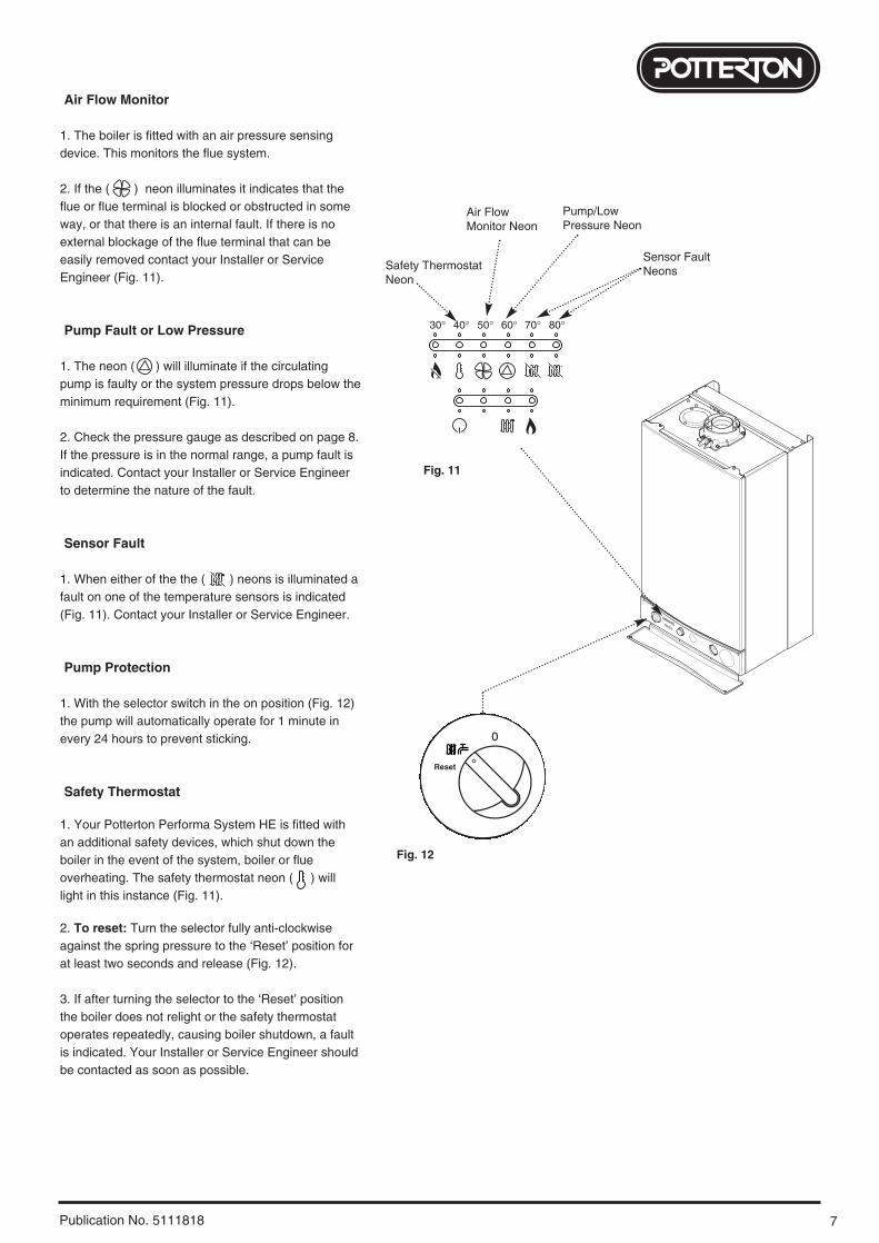
7Publication No. 5111818
Air Flow Monitor
1. The boiler is fitted with an air pressure sensingdevice. This monitors the flue system.
2. If the ( ) neon illuminates it indicates that theflue or flue terminal is blocked or obstructed in someway, or that there is an internal fault. If there is noexternal blockage of the flue terminal that can beeasily removed contact your Installer or ServiceEngineer (Fig. 11).
Pump Fault or Low Pressure
1. The neon ( ) will illuminate if the circulatingpump is faulty or the system pressure drops below theminimum requirement (Fig. 11).
2. Check the pressure gauge as described on page 8.If the pressure is in the normal range, a pump fault isindicated. Contact your Installer or Service Engineerto determine the nature of the fault.
Sensor Fault
1. When either of the the ( ) neons is illuminated afault on one of the temperature sensors is indicated(Fig. 11). Contact your Installer or Service Engineer.
Pump Protection
1. With the selector switch in the on position (Fig. 12)the pump will automatically operate for 1 minute inevery 24 hours to prevent sticking.
Safety Thermostat
1. Your Potterton Performa System HE is fitted withan additional safety devices, which shut down theboiler in the event of the system, boiler or flueoverheating. The safety thermostat neon ( ) willlight in this instance (Fig. 11).
2. To reset: Turn the selector fully anti-clockwiseagainst the spring pressure to the ‘Reset’ position forat least two seconds and release (Fig. 12).
3. If after turning the selector to the ‘Reset’ positionthe boiler does not relight or the safety thermostatoperates repeatedly, causing boiler shutdown, a faultis indicated. Your Installer or Service Engineer shouldbe contacted as soon as possible.
30° 40° 50° 60° 70° 80°
Air Flow Monitor Neon
Pump/LowPressure Neon
Sensor Fault Neons
Reset
Fig. 11
Fig. 12
Safety ThermostatNeon

8 Publication No. 5111818
Central Heating System Pressure
1. The water pressure in the central heating systemis indicated by the pressure gauge.
2. With the system cold and the boiler not operatingthe pressure should be between 0.2 and 1.0 bar.During operation the pressure should not exceed 2.5bar, and will normally be between 1.0 and 2.0 (Figs.13 & 14).
3. A pressure of 3 or greater indicates a fault. Thesafety pressure relief valve will operate, at a pressureof 3 (Fig. 15). It is important that your Installer orService Engineer is contacted as soon aspossible.
4. The minimum pressure for correct operation is 0.2.If the pressure falls below 0.2, this may indicate aleak on the central heating system (Fig. 16).
To Shut Off the Boiler
1. For short periods: Turn the selector switch to theOff position (Fig. 17).
2. For long periods: Turn off the selector switch(Fig.17), electricity and gas supplies.
If your home is to be left unoccupied for longperiods during cold weather the boiler and wholesystem should be drained unless there isadditional frost protection.
3. Your installer will advise you about frost protectionand draining the system.
IMPORTANT: When the selector switch is in the‘0’ (Off) position the electrical supply to the boileris isolated. The boiler will not operate.
Frost Protection Mode
1. The frost protection feature will operate when theselector switch is in the On position.The gas and electrical supplies to the boiler must beon and then system pressure be within the rangedescribed above.
2. If the system temperature falls below 5°C, then theboiler will fire until the water temperature has beenraised.
3. Further frost protection can be incorporated byusing a frost thermostat to protect the whole system.
2
1
0 4
3
bar
2
1
0 4
3
bar
2
1
0 4
3
bar
2
1
0 4
3
bar
On/OffSelector Switch
Reset
Off Position
Fig. 17
Normal Pressure (when cold)
Normal Pressure (operating)
Fig. 13
Fault
Fig. 14
Below Minimum
Fig. 15
Fig. 16
Pressure Gauge

9Publication No. 5111818
Clearances around the Boiler (Figs. 18 & 19)
1. The minimum clear spaces needed around the boilermeasured from the casing are as follows:
Top - 200mmBottom - 200mmLeft Side - 5mmRight Side - 20mm/5mm*Front - 5mm (In Operation)
- 450mm (For Servicing)
*NOTE: The boiler can be operated with a clearanceof 5mm at the right. This is also sufficient for routinemaintenance. However a clearance of 20mm isrequired if it is necessary to remove the secondaryheat exchanger. This should be considered whensiting the appliance and in the event of anysubsequent alteration in the area of installation.
2. These areas must not be obstructed in any way.Blocking the clearance spaces may result in theboiler overheating and damage may occur.
3. The gas burning compartment of your boiler iscompletely sealed from the room in which it is fitted.Products from the combustion of gas are vented to theoutside through the flue terminal which must be keptfree from obstruction as this would interfere with thecorrect operation of the boiler.
4. The boiler may be installed in a cupboard if theseminimum clearances are kept. The compartmentshould be large enough to house the boiler andancillary equipment only.
5. IT SHOULD NOT BE USED AS A STORAGECUPBOARD.
Check List
1. If a fault develops, or is suspected, call your Installeror Service Engineer as soon as possible.
2. Go through the following check list before you makecontact.
a) Is the electricity supply on ?b) Is the selector switch in the On Position (giving a
green “Power On” neon) ?c) Is the red “Flame Failure” neon lit ? Turn the
On/Off/Reset selector fully anti-clockwise.d) Is the gas supply on ?e) Is the system pressure correct ?f) Is the boiler temperature control set high enough ?g) Is the time clock (if fitted) calling for heat ?h) Is the room thermostat (if fitted) set high enough ?i) Are the radiator valves open ?
200mm Min
780mm
450mm
200mm Min
20mm/5mm Min
see *NOTE:5mm Min
5mm Min
450mm Min
For ServicingPurposes
Fig. 18
Fig. 19In Operation

10 Publication No. 5111818
Cleaning the Outercase
The painted panels should be wiped with a dampcloth and then dried completely. DO NOT USEABRASIVE CLEANING AGENTS.
Spare Parts
IMPORTANT - Only a competent person should beused to service or repair this boiler.
1. Any repairs to the boiler will usually be theresponsibility of the Installer during the guaranteeperiod after which spare parts may be obtainedthrough approved Potterton stockists if required.
2. Quote the appliance name, model number andwhere possible the part number when orderingspares. A parts list is included in the Installation andServicing Instructions.
3. The name, model number and serial number canbe found on the information label on the back of thehinged lower door (see back page).

11Publication No. 5111818
Codes of Practice, most recent version shouldbe used
Legislation
Potterton declare that no substances harmful tohealth are contained in the appliance or used duringappliance manufacture.
The appliance is suitable only for installation in GBand IE and should be installed in accordance withthe rules in force, and only used in a suitablyventilated location.
In GB, the installation must be carried out by a CORGIRegistered Installer. It must be carried out in accordancewith the relevant requirements of the:• Gas Safety (Installation & Use) Regulations.• The appropriate Building Regulations either The
Building Regulations, The Building Regulations (Scotland), Building Regulations (Northern Ireland).
• The Water Fittings Regulations or Water Byelaws in Scotland.
• The Current I.E.E. Wiring Regulations.
Where no specific instructions are given, referenceshould be made to the relevant British Standard Code ofPractice.
In IE, the installation must be carried out by a competentPerson and installed in accordance with the currentedition of I.S. 813 ‘Domestic Gas Installations’, thecurrent Building Regulations and reference should bemade to the current ETCI rules for electrical installation.
All systems must be thoroughly flushed and treatedwith inhibitor.
In GB the following Codes of Practice apply:Standard ScopeBS 6891 Gas Installation.BS 5546 Installation of hot water supplies for
domestic purposes.BS 5449 Forced circulation hot water systems.BS 6798 Installation of gas fired hot water boilers.BS 5440 Part 1 Flues.BS 5440 Part 2 Ventilation.BS 7074 Expansion vessels and ancillary equipment
for sealed water systems.BS 7593 Treatment of water in domestic hot water
central heating systems.
In IE the following Codes of Practice apply:Standard ScopeI.S. 813 Domestic Gas Installations.The following BS standards give valuable additional information;BS 5546 Installation of hot water supplies for
domestic purposes.BS 5449 Forced circulation hot water systems.BS 7074 Expansion vessels and ancillary equipment
for sealed water systems.BS 7593 Treatment of water in domestic hot water
central heating systems.

All descriptions and illustrations provided in this leaflet have been
carefully prepared but we reserve the right to make changes and
improvements in our products which may affect the accuracy of the
information contained in this leaflet. All goods are sold subject to
our standard Conditions of Sale which are available on request.
General Enquiries (GB)
Tel. 08706 060 780Technical (GB)
Tel. 08706 049 049Service (GB)
Tel. 08706 096 096Fax. 01926 410 006
Literature Request (GB)
Tel. 08706 060 623
Technical (IE)
Tel. 1850 560570
BAXI POTTERTONA Trading Division of Baxi Heating UK LtdBrownedge Road Bamber Bridge Preston Lancashire PR5 6UPAfter Sales Service 08706 096 096 Technical Enquiries 08706 049 049Website www.potterton.co.uk
company
Publication No. 5111818 - Iss. 2 (04/2005)
When contacting Baxi Potterton please have thefollowing information to hand:
Appliance NameModel NumberSerial Number
A label giving these details is situated on the rearof the hinged lower door panel.
Information Label
Hinged LowerDoor Panel
923.689.2