pouch motors: printable soft actuators integrated …...original article pouch motors: printable...
TRANSCRIPT

ORIGINAL ARTICLE
Pouch Motors:Printable Soft Actuators Integratedwith Computational Design
Ryuma Niiyama,1 Xu Sun,2 Cynthia Sung,3 Byoungkwon An,3 Daniela Rus,4 and Sangbae Kim2
Abstract
We propose pouch motors, a new family of printable soft actuators integrated with computational design. Thepouch motor consists of one or more inflatable gas-tight bladders made of sheet materials. This printableactuator is designed and fabricated in a planar fashion. It allows both easy prototyping and mass fabrication ofaffordable robotic systems. We provide theoretical models of the actuators compared with the experimentaldata. The measured maximum stroke and tension of the linear pouch motor are up to 28% and 100 N, re-spectively. The measured maximum range of motion and torque of the angular pouch motor are up to 80� and0.2 N, respectively. We also develop an algorithm that automatically generates the patterns of the pouches andtheir fluidic channels. A custom-built fabrication machine streamlines the automated process from design tofabrication. We demonstrate a computer-generated life-sized hand that can hold a foam ball and performgestures with 12 pouch motors, which can be fabricated in 15 min.
Introduction
Accelerating the design and manufacturing of phys-ical systems from ideas is one of the main challenges in
robotics. Manufacturing conventional robotic platforms re-quires rather complex processes to assemble constituentcomponents: frame, sensors, actuators, and electronics. Ex-pensive components and complex assembly processes driveup the cost of robotic systems and limit commercializationopportunities. The goal of this research is to design andfabricate robotic systems by print technologies, which willshift the paradigm of robot development.1 An integratedfabrication method for making robots allows both profes-sionals and nonprofessionals to design and fabricate afford-able customized robotic systems.
Automating robot fabrication from design to assembly isimportant for reducing prototyping costs. Recent advance-ments in three-dimensional (3D) printing technologies allowfor affordable rapid prototyping of arbitrary structures withplastic, metal, and rubber. Although such technology drasti-cally expedites prototyping processes, the available materialsfor 3D printing are still limited and cannot yet replace unique
anisotropic raw material properties. An early approach to in-tegrated fabrication is shape deposition manufacturing (SDM)applied in robotics.2,3 The SDM integrates actuators, sensors,and linkage mechanisms encapsulated in the process of castingstructural materials without fasteners. Another approach forfacilitating the integration of robotic components is to combinemultiple layers of planar sheets and create a 3D robot byfolding. Folding laser-machined composite laminates cancreate links and joints.4,5 Self-folding origami techniques6 canautomate the folding process of lightweight structures. Thereconfigurable modular robot7 and programmable structures8,9
are also approaches that can potentially provide a customizedrobotic system with minimum assembly processes.
New fabrication techniques have been developed forprintable components such as instant circuits,10 printablebatteries,11 and printable optics.12 These rapid prototypingtechnologies minimize assembly time and achieve a mono-lithic system that integrates multiple components.
Although these techniques facilitate the development ofprintable robotic systems, developing techniques to print ac-tuators has been a challenging task. This is because typicallythe fabrication of an actuator requires integrating multiple
1Department of Mechano-Informatics, School of Information Science and Technology, University of Tokyo, Tokyo, Japan.2Department of Mechanical Engineering and 3CSAIL, Massachusetts Institute of Technology, Cambridge, Massachusetts.4Autodesk Research, San Francisco, California.
SOFT ROBOTICSVolume 2, Number 2, 2015ª Mary Ann Liebert, Inc.DOI: 10.1089/soro.2014.0023
59

materials in rather complex geometries. For example, togenerate electromagnetic force, highly conductive materialsare combined with materials with special magnetic prop-erties in complex 3D shapes. Compared with electromag-netic actuation, electrostatic actuation requires fewer specialmaterials and a less complex fabrication process,13 althoughthe electrostatic actuator requires a substantially large-surface-area device and a high-voltage power supply togenerate workable force.
Thermally responsive materials such as shape memoryalloys and shape memory polymers also are candidates forsimple actuation methods.8,14,15 However, the temperaturecontrol has low bandwidth and limited energy efficiency, andmost of them are not reliable over multiple cycles.
Fluidic actuation offers the benefit of simplicity. Pneu-matically driven elastomer (specifically, silicone rubber) isa widely used soft robotics technique.16 This actuationmethod uses volume expansion of very soft materials suchas silicone rubber by pressure modulation. Fiber-reinforcedmaterials and elastomer composites17 are employed forselective deformation.
Microfluidic actuators have been explored in the field ofmicroelectromechanical systems (MEMS) using various fab-rication techniques.18 Specifically, a membrane actuator calledmicroballoon actuator is used for microrobotics.19,20 Becausethe microactuators rely on MEMS-specific materials andfabrication techniques such as etching, lithography, and spincoating, the output force/moment are neither scalable nor us-able by robots beyond the millimeter scale. Moreover, in themicroballoon actuator, the considerable elastic deformation ofthe microballoon makes theoretical analysis difficult.21
Pneumatic artificial muscle (PAM) actuator, a type of fluidicactuator, is a candidate printable actuator. Unlike hydraulic orpneumatic cylinders, PAM has no sliding components and hasinherent compliance and structural flexibility. McKibben-typePAM consists of a few components: an elastic tube, a braidedsleeve, and end fittings. Although PAM results in other im-proved structures,22,23 it has a bulky cylindrical shapes.
In this article, we introduce the ‘‘pouch motor,’’ a newprintable actuator that allows automated design and fabrica-tion for affordable robotic applications. We chose fluidicactuators for their structural simplicity and ease of fabrica-tion. This work is an extension of a previous publication.24
The two-dimensional (2D) design of the actuator is suitable
for seamless connection with existing design tools. We de-veloped a customized algorithm to compute robotic designswith pouch motors. In contrast with recent progress in flatPAM25 that is based on mold casting silicone rubber, wefocused on significantly simplified dry manufacturing pro-cess combined with automated computational design.
This article contributes by providing planar pneumaticactuators that can be integrated with printable robot systems.First of all, we investigate the theoretical model of the ac-tuator with measurement data. Our contribution also includesboth computer-controlled fabrication and automated designalgorithm for robotic applications. We develop two practicalfabrication methods for the planar actuator: heat stampingand heat drawing. We apply automated design to the actua-tors and demonstrate on the printable robot hand.
The remainder of this article is structured as follows: In thesection Pouch Motors Characterization, we describe a basicconcept of the proposed soft actuators and a design workflowfor the printable robotic system. Then, we discuss a theoreticalmodel of the actuator supported by experimental results. Inthe Fabrication Methods section, we describe fabricationmethods to implement the actuators based on heat drawingand heat stamping method. In the section Automated Designwith Pouch Motors and the section Robotic Applications, wedemonstrate an algorithm to automatically generate a 2Ddesign for a robotic system driven by these planar actuators.We conclude the work with a summary of contributions andfuture work in the Conclusions section.
Pouch Motors Characterization
Design workflow
The design process for a printable pouch motor robot isshown in Figure 1. The user provides the position of the jointsand connectors as well as the shape of the robot. Upon userinput, the system generates 2D patterns of the actuator, texture,and structure layers. This 2D form factor enables computer-aided design and simplifies fabrication. Each layer, includingthe actuator layer, is printable by planar fabrication tools. Theactuator layer is a group of pouch motors and fluidic channelsprinted on a duplex thermoplastic film. The texture layer is acolored pattern printed on paper by inkjet/laser printer. Thestructure layer is a scaffold of the actuator made of stiff ma-terial such as paper, fiberboard, and plastics. All the layers
FIG. 1. Overview of the design process for the printable robots with pouch motors. Based on the user input, our systemgenerates the full design of a pouch motor network. The image on the right is an example of a robotic application: a planarlife-sized robotic hand popping out from a cardboard. Color images available online at www.liebertpub.com/soro
60 NIIYAMA ET AL.

require cutting process by laser cutter or cutting plotter. Fi-nally, the layers are combined in alignment with double-sidedadhesive film/tape or glue. After connecting a control systemand initiating a self-folding process, the robot is operable.
Basic function
Pouch motors convert the mechanical work of fluid, suchas air, water, and oil, into the deformation of inflatable planarpouches. Changes in length and in curvature are used for thelinear (translational) pouch motor and the angular (rotational)pouch motor, respectively (Fig. 2). Stiff output tabs are at-tached to the edges of the pouch to deliver mechanical power.
The pouches are fabricated by bonding two gas-tightsheets. We chose a heat bonding method that is available forthermoplastics, in terms of performance and manufacturingtime. Two heat bonding methods are developed: heatstamping and heat drawing.
Theoretical model of the pouch
We developed a mathematical model of the pouch motor.We focus on two types of joint actuation using the inflatablepouch: linear contraction and angular rotation (Fig. 3). Thehinged angular pouch motor is mechanically stable but hassmaller range of motion than the angular pouch motorwithout a hinge.
The initial state of the pouch with no pressure is a flatsquare, and the geometry of the pouch under positive pressureP is an airfoil shape with cylindrical surfaces on the top andthe bottom (Fig. 4a). The pouch on the hinged structure has acylindrical surface only on the one side (Fig. 4b). As Vh, thevolume of the pouch V, increases, the radius of the curvature rof the cylindrical surfaces decreases. We assume that themembrane of the pouch has zero bending stiffness and isinextensible. Thus, we assume that there is no elastic energy
stored in the membrane. We also assume that the width of thepouch D remains constant as it is inflated and the side sur-faces are ignorable.
Assuming that the surfaces of the pouch are cylindrical, weobtain Equations (1) and (2):
L0¼ 2rh (1)
r sin h¼ L
2(2)
where L0 is the initial length when the pouch is flat, r is theradius of the curve of the membrane, h is the central angle ofthe circular segment, and L is the length of the chord or thelength of the pouch.
angular pouch motor linear pouch motor
deformation
contraction rotation
extensiona
b c
FIG. 2. (a) Possible dimension change of a pouch. Modesof motions actuated by pouch motors can be (b) linear or (c)angular. The gray and white parts indicate inflatable pou-ches and stiff structure, respectively.
M
M
rotation (open)
Mh
Mh
f h
rotation (hinged)
F
F
contraction
smalloverlaps
pouch outputtab
La
b
c
f
FIG. 3. Actions of the pouches: (a) contraction; (b) rota-tion, assuming that output tabs are tangent with the curve ofthe membrane on one side; and (c) rotation with a hingedmechanical structure.
free pouch
pouch on a hinged structure
r θ θ
L0
L
D
P, V
r θ θ
hL0
L
D
P, Vh
a
b
f
f
FIG. 4. Model of the single pouch: (a) a free pouch withcylindrical surfaces on the top and bottom, and (b) a pouchon a hinged joint.
POUCH MOTORS: PRINTABLE PLANAR SOFT ACTUATORS 61

From Equations (1) and (2), by eliminating the radius r, weobtain the length of the pouch; that is,
L(h)¼ L0
sin hh
(3)
The above Equation (3) is applicable in both of the pouches.The volume V of the free pouch (Fig. 4a) can be derived as
V(h)¼AD¼ L02D
2
h� cos h sin h
h2
� �(4)
where A is the cross-sectional area of the pouch and D is awidth of the pouch.
The volume Vh of the pouch with hinged structure can bederived using a cross-sectional area of the pouch Ah and thewidth of the pouch D as follows:
Vh(h)¼AhD
¼ L02D
h� cos h sin hþ sin hffiffiffiffiffiffiffiffiffiffiffiffiffiffiffiffiffiffiffiffiffiffiffiffiffih2� ( sin h)2
p4h2
(5)
Linear pouch motor
The work of the fluid in the pouch is transformed into tensionforce F in the case of a linear pouch motor. The energy con-servation corresponding to a virtual translation dL becomes
�FDL¼PdV (6)
where F is the tension force, P is the inner pressure of thepouch, dL is the small displacement in length, and dV is thesmall displacement in volume.
We already have both the length and the volume [Eqs. (3)and (5)] of the pouch as a function of the parameter h. Weobtain the following result:
F(h)¼ �PdV
dL¼ �P
dv=dhdL=dh
(7)
F(h)¼ L0DPcos h
h(8)
Now we introduce a strain Le as the ratio of total defor-mation to the initial length:
Le¼L0� L
L0
¼ 1� sin hh
(9)
The theoretical maximum contraction ratio of the linearpouch motor is Le(p=2)¼ p� 2
p � 0:363 (36.3%). The maxi-mum force output is observed when L = L0. When h/0,Equation (7) says F/N. In reality, the linear pouch motorhas finite maximum output force because material can stretchby the pressure and the tension force.
Angular pouch motor
Open structure (ideal). We consider an ideal model ofthe angular pouch motor based on the free pouch model
(Figs. 3b and 4a) in which the overlaps between the pouchand output tabs are sufficiently small. The work of the fluidin the pouch is transformed into moment (torque) M. Theenergy conservation corresponding to a virtual rotation d/becomes
Md/¼PdV (10)
The output angle u is a function of h; that is,
/(h)¼ 2h (11)
We obtain the following result:
M(h)¼PdV
d/¼P
dV=dhd/=dh
(12)
M(h)¼ L02DP
cos h( sin h� h cos h)
2h3(13)
The theoretical maximum range of motion of the angularpouch motor with open structure is zero to p rad (180�). Themaximum moment is observed when / = 0. In practical use,because of the small overlaps between rigid output tabs andedges of the pouch (Fig. 3b), measured maximum range ofmotion might be less than 180�.
Hinged structure. The angular pouch motor with openstructure is suitable for small-load applications such asanimated origami structure. However, the open edges of thetabs will dig into the pouch with overload. By adding ahinged structure, the deformation of the pouch is efficientlytransformed into the angular motion without undesiredpouch deformation. Moreover, the hinge can support shearand twist force that cannot be tolerated by only the flexiblepouch. On the other hand, hinged angular pouch motor haslimited maximum range of motion.
The pouch motor with hinged structure (Figs. 3c and 4b)has the output angle /h, which is a function of h. The fol-lowing equation can be derived from the geometric rela-tionships:
/h¼ cos� 1 2( sin h)2
h2� 1
� �¼ 2 cos� 1 sin h
h
� �(14)
We obtain the following result for the moment Mh:
Mh(h)¼PdVh
d/h
¼PdVh=dhd/h=dh
(15)
Mh(h)¼ L02DP
8h2
�� 1þ h2þ cos 2h
�ffiffiffi2p
cos hffiffiffiffiffiffiffiffiffiffiffiffiffiffiffiffiffiffiffiffiffiffiffiffiffiffiffiffiffiffiffiffiffiffiffiffiffiffi� 1þ 2h2þ cos 2h
p � (16)
The theoretical maximum range of motion of the angularpouch motor with hinged structure is zero to 1.63 rad (95.3�).The maximum moment is observed when /h = 0 and Mh
(0) > M(0).
62 NIIYAMA ET AL.

Properties of the linear actuators
We tested a linear pouch motor with three series pouches(Fig. 5a). The test sample is made from a polyethylene sheetwith a thickness of 0.102 mm (4mil). The pouches aremanually fabricated by using a line heat sealer. Each pouchhas the effective width D = 0.075 m and the initial lengthL0 = 0.025 m. The measurement of the tension force is aquasi-static process, which starts shortening from L = L0 andreturns to the initial length at a velocity of about 25 mm/min.The inner pressure of the pouch is kept constant by feedbackcontrol during the experiments.
The theoretical curves are the parametric plot of theEquations (8) and (9) for 0 < h £ p/2. Force F is a monoton-ically decreasing function of the strain Le in any pressure andis slightly concave up.
The comparison of the theoretical and the measured force–length properties is shown in Figure 6. The recordings arelow-pass filtered with a cutoff frequency of 0.4 Hz. The
measured data trend similarly to the model. The measuredmaximum stroke and force of the linear pouch motor are about28% of the initial length and 100 N (10 kgf), respectively,in 40 kPa. This performance is comparable to McKibbenartificial muscle.
We observed agreement between the theoretical curveand the measured data in small working pressures under10 kPa. Because of the elasticity of the sheet material, theinextensible assumption is no longer valid in high workingpressure over 40 kPa. This results in a relatively large errorin high pressure. Even a fully loosened pouch motor(tension equal to zero) cannot reach the theoretical maxi-mum contraction ratio. The elastic deformation also affectsthe maximum tension force. In the initial length (L = L0),the pressured pouch cannot remain flat and has somecurvature. Thus, the measured data have limited tensionforce in small strain. Another factor is the incomplete in-flation in large contraction due to the 2D-based design ofthe pouch.
Properties of the angular actuators
We tested an angular pouch motor with hinged structure(Fig. 5b). The test sample is made from a polyethylene sheet witha thickness of 0.049 mm. We use a single pouch that has theeffective width D = 0.075 m, and the initial length L0 = 0.025 m.The pouch is fabricated by using the heat drawing machine.The measurement of the moment is a quasi-static process thatstarts bending from uh = 0 until Mh = 0 and then returns to theinitial angle.
The theoretical curves are the parametric plot of theEquations (14) and (16) for 0 < h £ p/2. The moment Mh is amonotonically decreasing function of the angle uh in anypressure.
The comparison between theoretical and measured mo-ment–angle properties is shown in Figure 7. The recordingsare low-pass filtered with a cutoff frequency of 0.4 Hz. The
FIG. 6. The force–length relationship of the linear pouchmotor at various pressures. Solid lines show measured data,and dotted lines show the corresponding theoretical curves.The arrows indicate outward and return of the hysteresiscurve. The horizontal axis shows the ratio of the total de-formation to the initial length L0. Color images availableonline at www.liebertpub.com/soro
FIG. 7. The moment–angle relationship of the angularpouch motor with hinged structure at various pressure. Solidlines show measured data, and dotted lines show the cor-responding theoretical curves. The arrows indicate outwardand return of the hysteresis curve. Color images availableonline at www.liebertpub.com/soro
FIG. 5. The experimental setup for (a) tension and (b)moment measurements. Supply pressure of the pouch isfeedback controlled during the testing.
POUCH MOTORS: PRINTABLE PLANAR SOFT ACTUATORS 63

measured maximum angle and moment of the hinged angularpouch motor are about 80� and 0.2 Nm, respectively, in20 kPa.
We observed agreement between the theoretical curve andthe measured data in small working pressures under 5 kPa.Because the inflated pouch does not have a perfect cylindricalshape, side wrinkles could have prevented the inflation androtation at larger angle positions. In addition, the elasticelongation of the membrane interferes with both maximummoment and range of motion at large pressures.
Fabrication Methods
Overview
Pouch motors can be made of thermoplastic films. Twosheets of plastic film are stacked together and thermallybonded by applying heat and pressure along the line of thebonding to form a pouch. A similar thermal bonding methodis used to seal bubble wraps and plastic food storage bags. Tobond the two sheets along the desired shape, we develop twoautomated fabrication methods: heat stamping and heatdrawing.
Heat stamping involves a lengthy workflow but allows forrapid manufacturing. First, a stamp (or printing block) mustbe made and attached to the heat press machine. Althoughmachining a stamp takes longer process, once the stamp isready, it is easy to duplicate the same design quickly withconstant quality, thus making this method suitable for massfabrication.
The workflow for heat drawing, in contrast, is flexible andprogrammable but prolongs manufacturing time. Once thepouch design is made, a heat pen attached on a three-axisCNC stage draws the outline of the design. The heat drawingmethod is suitable for on-demand prototyping in a smallquantity.
Fabrication by stamping
The heat stamping machine consists of a heat press witha die mounted on its top plate (Fig. 8). Two layers ofthermoplastic films and a nonsticky film on the top areloaded onto the machine table. We used a polytetra-fluoroethylene (PTFE)-coated glass fiber fabric to preventplastic films from sticking to the die. After heating up thedie to the desired temperature, the die is pressed onto the
film layers and held for a short period of time. Then thefilms can be taken out for cooling. Finally, pouch motorscan be cut from the films. The quality of pouch motorsmade with thermal bonding is related to multiple param-eters (Table 1).
In our process, we use 0.102-mm (4 mil)-thick vinyl filmscovered with a layer of 0.127-mm (5 mil)-thick PTFE-coatedglass fiber fabric as the release sheet to prevent vinyl filmmelt onto the die. Line width on the die is 1.6 mm. We need atemperature of around 245�C when pressing the die onto thefilms for about 5 s.
Fabrication by drawing
The heat drawing method uses a soldering iron that ispressed against two thermoplastic films to apply heat andpressure (Fig. 9). The position of the heated metal tip of thesoldering iron is controlled by a three-axis CNC stage.Nonsticky films are stacked on top of two layers of targetthermoplastic films to minimize friction between the tip andthe films. These materials are held on the drawing tablebeneath the heated tip. The heat-drawing machine uses anelastic baseboard on the table to achieve stable contactpressure. A computer interprets a line of G-code and com-mands the machine to move the heated tip to draw thedesign.
The width of the bonding lines by drawing has uniformwidth as shown in the sample (Fig. 9). In contrast, the
FIG. 8. The heat stamping system and a sample of the fabricated pouch. Color images available online at www.liebertpub.com/soro
Table 1. Heat Bonding Parameters
Bonding method
Heat stamping Heat drawing
Line width Die patternwidth
Tip diameter, drawingforce, and baseboard rigidity
Temperature Die temperature Pen-tip temperatureProcess time Stamping time Drawing speedSealing force Stamping
pressureDrawing force
Commonparameters
Thickness and type of thermoplastic
Thickness and type of nonstick sheet
64 NIIYAMA ET AL.

stamped lines determined by the die design have morecomplexity. The machine also can draw a thick line by addingoffset parallel lines or drawing serpentine pattern.
The quality of heat bonding is determined by multipleparameters (Table 1). We use thermoplastic films from 0.05to 0.2-mm (2–8 mil)-thick and 0.076-mm (3 mil)-thickPTFE-coated glass fiber fabric for nonstick and low-frictiondrawing. We use 375 mm/min as the limiting speed of thedrawing, and set the heated metal tip temperature to 357�C.The resulting drawing force to make workable pouches isabout 6.9 N.
Automated Design with Pouch Motors
Overview
The pouch motor is not only printable but also it issuitable for automated design. The pouch motor designcan be reduced to 2D graphics and not suffered fromcomplicated 3D geometric constraints. The users canbenefit from computer-based optimization and simulation.Moreover, the automated design can provide an oppor-tunity for nonprofessional people to design robot systems.This section describes the design algorithm for softwaredevelopers.
The design algorithm for robots with pouch motors com-piles a 3D origami design (a folded state of a paper structureencoded with a crease pattern and folded angles) or a 3D
polygon mesh into a design for pouch motor robots. Thisautomated design process has three parts:
1. Creating unfolded 2D structure2. Positioning pouch motors and routing air channels3. Generating paths for CNC fabrication
Creating a 2D pattern from a 3D model
Several algorithms exist to unfold 3D meshes or origami de-signs.26–28 We modified the algorithm for self-folding sheets29 tooutput a 2D unfolded structure for later process. We transformthe 3D model as a graph and unfold it using Prim’s algorithm (aminimum spanning tree algorithm).30 As the algorithm unfoldsthe 3D model, it maintains the relationship between the vertexesof the unfolded 2D pattern and the 3D model.
Positioning pouches and routing
Once a 2D pattern has been developed, users can in-dicate groups of actuated folds. Our system places pou-ches on the fold pattern and routes air channels to allowgroups of pouches to be actuated simultaneously. Thecurrent system is exclusive to angular pouch motors at-tached on folds. We use the following steps, depicted inFigure 10:
Input. The user provides a fold pattern G = (B, F), whereB � R2 is the boundary of the unfolding and F is a list of
FIG. 9. The heat drawing system and a sample of the fabricated pouch. Color images available online at www.liebertpub.com/soro
FIG. 10. Procedure for placing pouches and routing air channels on a fold pattern. Color images available online atwww.liebertpub.com/soro
POUCH MOTORS: PRINTABLE PLANAR SOFT ACTUATORS 65
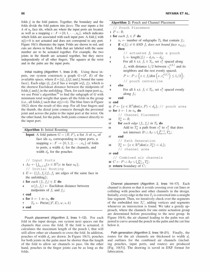
folds fi in the fold pattern. Together, the boundary and thefolds divide the fold pattern into faces. The user inputs a listA of np face ids, which are where the input ports are located,as well as a mapping s : F/f0, 1, � � � , npg, which indicateswhich folds are associated with each input port. A fold fi withs(fi) = 0 is not actuated and does not correspond to any port.Figure 10(1) illustrates the input. Folds are shown in red, andcuts are shown in black. Folds that are labeled with the samenumber are to be actuated together. For example, the twojoints in the thumb are actuated together, but they moveindependently of all other fingers. The squares at the wristand in the palm are the input ports.
Initial routing (Algorithm 1, lines 2–8). Using these in-puts, our system constructs a graph G = (F, E) of theavailable space, where E = {(fi, fj)jfi and fj bound the sameface}. Each edge (fi, fj)˛E has a weight w(fi, fj), which isthe shortest Euclidean distance between the midpoints offolds fi and fj in the unfolding. Then, for each input port ak,we use Prim’s algorithm30 to find the subgraph of G withminimum total weight that spans all the folds in the group(i.e., all folds fi such that s(fi) = k). The blue lines in Figure10(2) show the result of this step. For all four fingers andthe thumb, the distal joint connects through the proximaljoint and across the palm to the input port at the wrist. Onthe other hand, for the palm, both joints connect directly tothe input port.
Pouch placement (Algorithm 2, lines 1–12). For eachfold in the input design, our system next spaces out thechannels that cross the fold. If the fold is actuated, itcalculates the maximum length of the pouch li that willstill allow other air channels to cross the fold. In addition,pouches of width dp are drawn. In Figure 10(3), pouchesfor both joints in the palm must be shorter than the lengthof the fold to allow air channels to pass. On the otherhand, pouches in the finger joints can be as long as thefolds.
Channel placement (Algorithm 2, lines 14–17). Eachchannel is drawn so that it avoids crossing over cut lines orcolliding with pouches and other channels in the design.Initially, every edge in the tree Tk is converted into a straightline segment. Then, we iteratively check over the segmentsof the embedded tree Tk
e, adding vertices and segmentswhenever an intersection is found. We take a greedy ap-proach, where the channels for one entire actuation groupare determined before proceeding to the next group. InFigure 10(4), the air channel leading to the palm was ad-justed to curve around the pouch in the palm and the cut linebelow it.
Path generation (Algorithm 2, lines 18–21). Finally, theroutes for the air channels are thickened to width dc
and outlines for the combined air channels (includ-ing pouches, input ports, and routes) are produced[Fig. 10(5)]. The drawing is saved in DXF format forfabrication.
66 NIIYAMA ET AL.

Digital fabrication
With the DXF file, we can generate tool paths to make a diefor heat stamping or to control a heat drawing machine. Wegenerated a computer numerical control program (G-code)with CAM software for the computer-controlled fabrication.
Because of the unique setup of heat drawing machine, afew calibration steps are necessary for the z axis to adjustdrawing forces. Following the calibration, codes are loaded tothe machine and pouches can be printed.
Robotic Application
Miniature pneumatic control system
We developed a portable pneumatic control system thatconsists of a miniature pump, tiny solenoid valves, battery,and microcontroller unit (Fig. 11).
The system can share one pump for multiple pouch motors.Two 2-way 3-port valves are needed per pouch to achieve the
three states: supply, exhaust, and keep air. For the binaryfunctions (supply/exhaust), the control system requires onlyone solenoid valve per pouch.
Robotic hand
We developed several versions of a life-sized robotic hand(Fig. 12). The robotic hand can perform hand gestures, andgrasp a paper cup and a foam ball by supplying air through theports. The compliant joints enable the hand to adapt to anobject with irregular shape such as human hand. A hand madeof paper board structure, with weight of 20 g, experienceddelamination due to the tension of the pouch. A hand made ofacrylic board structure, with weight of 80 g, has stable hingedstructure. Robotic hands are fabricated by using both heatstamping and heat drawing method. Stamping the actuatorlayer takes about 10 s, and heat drawing takes about 10 min.We found no significant difference in performance of theactuators with two fabrication methods in fixed pattern. The
FIG. 11. Left: the pneumatic cir-cuit for controlling two pouches in-dividually. Right: the implementedportable miniature pneumatic con-trol system that is used for the ro-botic hand. Color images availableonline at www.liebertpub.com/soro
FIG. 12. The planar printable ro-botic hand driven by the hingedpouch motors fabricated on a lettersize board. The hand can grip humanhand, grasp a foam ball, and hold apaper cup. Color images availableonline at www.liebertpub.com/soro
POUCH MOTORS: PRINTABLE PLANAR SOFT ACTUATORS 67

aspect ratio of the pouch should be 1:2 or longer along theactuated edge to obtain uniform cylindrical shape when in-flated. We also observed that the pouch that is slightly longerthan the length of the actuated edge could achieve largertorque without peel off from the structure.
The miniature pneumatic control system can control twogroups of air channels. Tubing connectors are attached onthe actuator layer by double-sided tape. We put pneumatictubes for all the fingers except the thumb together and linktubes for thumb and palm joints together. Fully extendedfingers can produce the force about 0.6 N on the fingertipwith the air pressure of 40 kPa. The maximum range ofmotion for each joint is about 80� (Fig. 13). The speed of theextension and flexion of the finger is up to 1 Hz with theportable pneumatic control system. We conducted both
programmed sequence of motion and interactive move-ments based on the push buttons.
We have tested our design algorithm on several configura-tions of actuators and input ports for the robotic hand (Fig. 14).All those samples are fabricated by using the heat drawingmethod. Air channels are arranged so that they do not cross overeach other or over cuts in the fold pattern. Comparing resultsshow that the pouch lengths are adjusted to accommodate airchannels. Other examples show different actuator groups; airchannels branch to simultaneously actuate multiple fingers.
Conclusions
We propose a printable soft actuator that we term a ‘‘pouchmotor.’’ This planar pneumatically driven actuator allows a
FIG. 13. The range of mo-tion of the robotic hand. Left:overall view. Right: side viewof the thumb extension andflexion.
FIG. 14. The computer-generated robotic hands de-sign with different groupingof pouches. These designsare fabricated by the heatdrawing method. Color ima-ges available online at www.liebertpub.com/soro
68 NIIYAMA ET AL.

streamlined design and fabrication process. We provide both asemiautomated design process of the pouch motors with airchannels, and a fabrication method based on heat bonding. Thepouch motors can be scaled up or down using different mate-rials and fabrication methods. The mathematical models of thelinear pouch motor and angular pouch motor can predictmeasured values. We demonstrate the proposed design methodwith a planar robotic hand with 12 pouch motors. The systemcan provide a variety of air channel arrangements correspondingto the different user inputs. Future work may encompass morecomplicated 3D structures and optimized design methods. In-tegration of a sensing layer with feedback control is the next steptoward developing fully printable robots.
Acknowledgments
This work was funded in part by National Science Founda-tion Grant Nos. 1240383 and 1138967. Support was also pro-vided in part by the Department of Defense under the NationalDefense Science and Engineering Graduate Fellowship Pro-gram. We are grateful for this support.
Author Disclosure Statement
No competing financial interests exist.
References
1. Onal CD, Wood RJ, Rus D. Towards printable robotics: ori-gami-inspired planar fabrication of three-dimensional mech-anisms. In: Proceedings of the IEEE International Conferenceon Robotics and Automation (ICRA), 2011, pp. 4608–4613.
2. Bailey SA, Cham JG, Cutkosky MR, Full RJ. Biomimeticrobotic mechanisms via shape deposition manufacturing.In: Proceedings of the 9th International Symposium ofRobotics Research, 1999, pp. 321–327.
3. Dollar AM, Howe RD. A robust compliant grasper viashape deposition manufacturing. IEEE/ASME Trans Me-chatron 2006;11:154–161.
4. Wood RJ, Avadhanula S, Menon M, Fearing RS. Micro-robotics using composite materials: the micromechanicalflying insect thorax. In: Proceedings of the IEEE Interna-tional Conference on Robotics and Automation (ICRA),2003, pp. 1842–1849.
5. Hoover AM, Fearing RS. Fast scale prototyping for foldedmillirobots. In: Proceedings of the IEEE InternationalConference on Robotics and Automation (ICRA), 2008, pp.886–892.
6. Felton SM, Tolley MT, Shin B, Onal CD, Demaine ED,Rus D, Wood RJ. Self-folding with shape memory com-posites. Soft Matter 2013;9:7688–7694.
7. Murata S, Yoshida E, Kamimura A, Kurokawa H, TomitaK, Kokaji S. M-TRAN: self-reconfigurable modular ro-botic system. IEEE/ASME Trans Mechatron 2002;7:431–441.
8. Hawkes E, An B, Benbernou NM, Tanaka H, Kim S,Demaine ED, Rus D, Wood RJ. Programmable matter byfolding. Proc Natl Acad Sci USA 2010;107:12441–12445.
9. Knaian AN, Cheung KC, Lobovsky MB, Oines AJ,Schmidt-Neilsen P, Gershenfeld NA. The milli-motein: aself-folding chain of programmable matter with a onecentimeter module pitch. In: Proceedings of the IEEE/RSJInternational Conference on Intelligent Robots and Systems(IROS), 2012, pp. 1447–1453.
10. Kawahara Y, Hodges S, Cook BS, Zhang C, Abowd GD.Instant inkjet circuits. In: Proceedings of the ACM Inter-national Joint Conference on Pervasive and UbiquitousComputing (UbiComp), 2013, pp. 363–372.
11. Sun K, Wei T-S, Ahn BY, Seo JY, Dillon SJ, Lewis JA. 3Dprinting of interdigitated Li-ion microbattery architectures.Adv Mater 2013;25:4539–4543.
12. Willis K, Brockmeyer E, Hudson S, Poupyrev I. Printedoptics: 3D printing of embedded optical elements for in-teractive devices. In: Proceedings of the ACM Symposiumon User Interface Software and Technology (UIST), 2012,pp. 589–598.
13. Egawa S, Niino T, Higuchi T. Film actuators: planar,electrostatic surface-drive actuators. In: Proceedings of theIEEE International Conference on Micro Electro Mechan-ical Systems (MEMS), 1991, pp. 9–14.
14. Seok S, Onal CD, Cho K-J, Wood RJ, Rus D, Kim S.Meshworm: a peristaltic soft robot with antagonistic nickeltitanium coil actuators. IEEE/ASME Trans Mechatron2013;18:1485–1497.
15. Haines CS, Lima MD, Li N, Spinks GM, Foroughi J,Madden W, Kim SH, Fang S, Jung de Andrade M, GoktepeF, Goktepe O, Mirvakili SM, Naficy S, Lepro X, Oh J,Kozlov ME, Kim SJ, Xu X, Swedlove BJ, Wallace GG,Baughman RH. Artificial muscles from fishing line andsewing thread. Science 2014;343:868–872.
16. Ilievski F, Mazzeo AD, Shepherd RF, Chen X, WhitesidesGM. Soft robotics for chemists. Angew Chem Int Ed2011;50:1890–1895.
17. Martinez RV, Fish CR, Chen X, Whitesides GM. Elasto-meric origami: programmable paper-elastomer compos-ites as pneumatic actuators. Adv Funct Mater 2012;22:1376–1384.
18. De Volder M, Reynaerts D. Pneumatic and hydraulic micro-actuators: a review. J Micromech Microeng 2010;20:043001.
19. Kawai F, Cusin P, Konishi S. Thin flexible end-effectorusing pneumatic balloon actuator. In: Proceedings of theIEEE International Conference on Micro Electro Mechan-ical Systems, 2000, vol. 89, pp. 28–35.
20. Lu Y, Kim C-J. Characterization of balloon-jointed micro-fingers. In: Proceedings of the ASME International Me-chanical Engineering Congress and Exposition, 2003, pp.311–316.
21. Gorissen B, Volder MD, Greef AD, Reynaerts D. Theore-tical and experimental analysis of pneumatic balloon mi-croactuators. Sens Actuat A 2011;168:58–65.
22. Bergemann D, Lorenz B, Thallemer A. Actuating means.U.S. Patent 6,349,746, Feb. 26, 2002.
23. Daerden F, Lefeber D. The concept and design of pleatedpneumatic artificial muscles. Int J Fluid Power 2001;2:41–50.
24. Niiyama R, Rus D, Kim S. Pouch motors: printable/inflat-able soft actuators for robotics. In: Proceedings of the IEEEInternational Conference on Robotics and Automation(ICRA), 2014, pp. 6332–6337.
25. Park Y-L, Santos J, Galloway KG, Goldfield EC, Wood RJ.A soft wearable robotic device for active knee motionsusing flat pneumatic artificial muscles. In: Proceedings ofthe IEEE International Conference on Robotics and Auto-mation (ICRA), 2014, pp. 4805–4810.
26. Tachi T. Origamizing polyhedral surfaces. IEEE Trans VisComput Graph 2010;16:298–311.
27. Takahashi S, Wu H-Y, Saw S, Lin C-C, Yen H-C. Opti-mized topological surgery for unfolding 3D meshes.Comput Graph Forum 2011;30:2077–2086.
POUCH MOTORS: PRINTABLE PLANAR SOFT ACTUATORS 69

28. Tachi T. Simulation of rigid origami. In: Proceedings of theOrigami4: International Conference on Origami in Science,Mathematics and Education (OSME), 2009, pp. 175–187.
29. An B, Miyashita S, Tolley MT, Aukes DM, Meeker L,Demaine ED, Demaine ML, Wood RJ, Rus D. An end-to-end approach to making self-folded 3D surface shapes byuniform heating. IEEE International Conference on Ro-botics and Automation (ICRA), 2014.
30. Prim RC. Shortest connection networks and some gener-alizations. Bell Syst Tech J 1957;36:1389–1401.
Address correspondence to:Ryuma Niiyama
Department of Mechano-InformaticsSchool of Information Science and Technology
University of TokyoEng. Bld. 2, Room 82D4, 7-3-1 Hongo, Bunkyoku
Tokyo 113-0033Japan
E-mail: [email protected]
70 NIIYAMA ET AL.