powdered magnesium—carbon dioxide rocket combustion ... · powdered magnesium—carbon dioxide...
TRANSCRIPT
NASA/TP—2007–215077
Powdered Magnesium—Carbon Dioxide Rocket Combustion Technology for In Situ Mars PropulsionJ.P. Foote* and R.J. LitchfordMarshall Space Flight Center, Marshall Space Flight Center, Alabama
September 2007
National Aeronautics andSpace AdministrationIS20George C. Marshall Space Flight CenterMarshall Space Flight Center, Alabama35812
*Intergovernmental Personnel Act employee in support of Marshall Space Flight Center; now affiliated with Jacobs Sverdrup
https://ntrs.nasa.gov/search.jsp?R=20080002287 2020-01-06T14:45:51+00:00Z
The NASA STI Program…in Profile
Since its founding, NASA has been dedicated to the advancement of aeronautics and space science. The NASA Scientific and Technical Information (STI) Program Office plays a key part in helping NASA maintain this important role.
The NASA STI program operates under the auspices of the Agency Chief Information Officer. It collects, organizes, provides for archiving, and disseminates NASA’s STI. The NASA STI program provides access to the NASA Aeronautics and Space Database and its public interface, the NASA Technical Report Server, thus providing one of the largest collections of aeronautical and space science STI in the world. Results are published in both non-NASA channels and by NASA in the NASA STI Report Series, which includes the following report types:
• TECHNICAL PUBLICATION. Reports of completed research or a major significant phase of research that present the results of NASA programs and include extensive data or theoretical analysis. Includes compilations of significant scientific and technical data and information deemed to be of continuing reference value. NASA’s counterpart of peer-reviewed formal professional papers but has less stringent limitations on manuscript length and extent of graphic presentations.
• TECHNICAL MEMORANDUM. Scientific and technical findings that are preliminary or of specialized interest, e.g., quick release reports, working papers, and bibliographies that contain minimal annotation. Does not contain extensive analysis.
• CONTRACTOR REPORT. Scientific and technical findings by NASA-sponsored contractors and grantees.
• CONFERENCE PUBLICATION. Collected papers from scientific and technical conferences, symposia, seminars, or other meetings sponsored or cosponsored by NASA.
• SPECIAL PUBLICATION. Scientific, technical, or historical information from NASA programs, projects, and missions, often concerned with subjects having substantial public interest.
• TECHNICAL TRANSLATION. English-language translations of foreign scientific and technical material pertinent to NASA’s mission.
Specialized services also include creating custom thesauri, building customized databases, and organizing and publishing research results.
For more information about the NASA STI program, see the following:
• Access the NASA STI program home page at <http://www.sti.nasa.gov>
• E-mail your question via the Internet to <[email protected]>
• Fax your question to the NASA STI Help Desk at 301– 621–0134
• Phone the NASA STI Help Desk at 301– 621–0390
• Write to: NASA STI Help Desk NASA Center for AeroSpace Information 7115 Standard Drive Hanover, MD 21076–1320
�
NASA/TP—2007–215077
Powdered Magnesium—Carbon Dioxide Rocket Combustion Technology for In Situ Mars PropulsionJ.P. Foote* and R.J. LitchfordMarshall Space Flight Center, Marshall Space Flight Center, Alabama
September 2007
Nat�onal Aeronaut�cs andSpace Adm�n�strat�on
Marshall Space Fl�ght Center • MSFC, Alabama 35812
*Intergovernmental Personnel Act employee �n support of Marshall Space Fl�ght Center; now affiliated with Jacobs Sverdrup
��
Ava�lable from:
NASA Center for AeroSpace Informat�on7115 Standard Dr�ve
Hanover, MD 21076 –1320301– 621– 0390
Th�s report �s also ava�lable �n electron�c form at<https://www2.sti.nasa.gov>
���
Table of ConTenTS
1. INTRODUCTION ......................................................................................................................... 1
2. MISSION RELEVANCE ............................................................................................................... 4
3. ROCKET ENGINE CONFIGURATION ISSUES ........................................................................ 7
4. RESEARCH AND DEVELOPMENT APPROACH ..................................................................... 8
4.1PhaseIAtmospher�cPressureBurner Configuration .............................................................. 8 4.2 Phase II Pressurized Combustor Configuration ...................................................................... 10 4.3 Phase III Prototypical Rocket Configuration .......................................................................... 10
5. CONCLUSIONS ............................................................................................................................ 11
REFERENCES ................................................................................................................................... 12
�v
lIST of fIGUReS
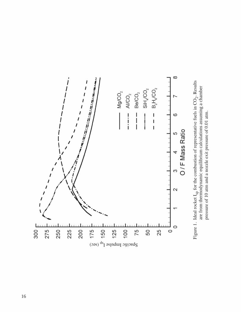
1. Ideal rocket Isp for the combustion of representative fuels in CO2. Results are from thermodynam�c equ�l�br�um calculat�ons assum�ng a chamber pressure of 10 atm and a nozzle exit pressure of 0.01 atm ............................................................... 16
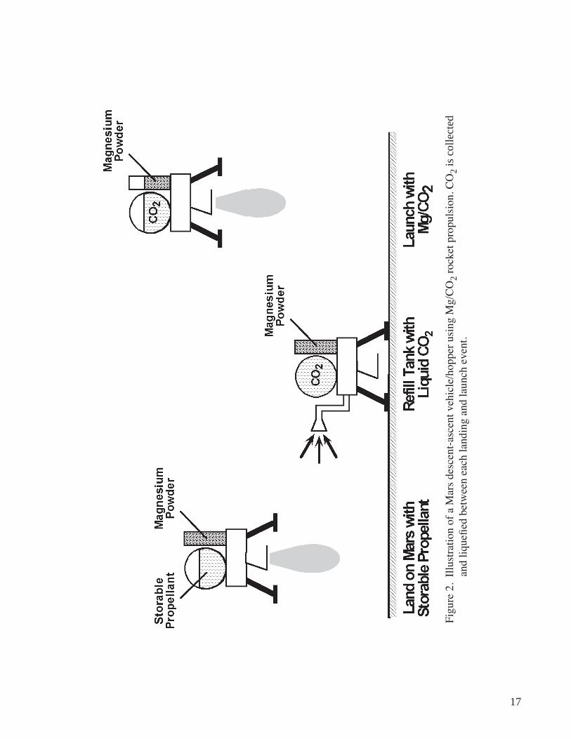
2. Illustration of a Mars descent-ascent vehicle/hopper using Mg/CO2 rocket propulsion. CO2 is collected and liquefied between each landing and launch event ............................ 17
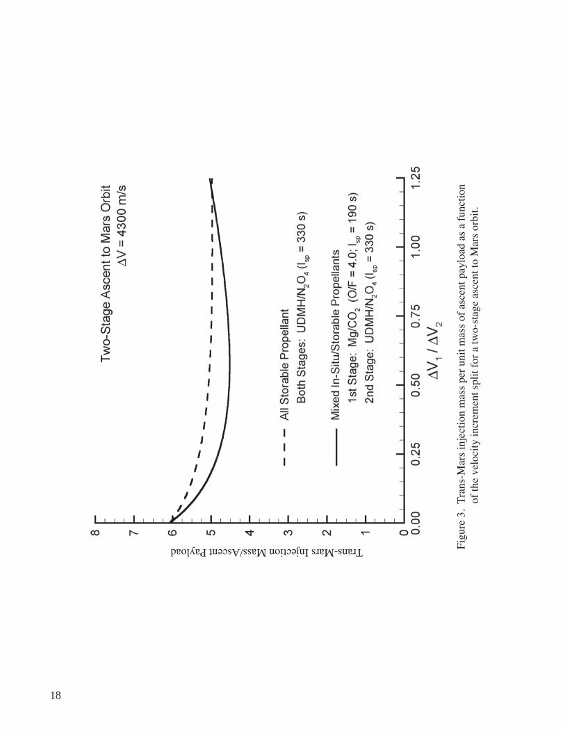
3. Trans-Mars injection mass per unit mass of ascent payload as a function of the velocity increment split for a two-stage ascent to Mars orbit ............................................ 18
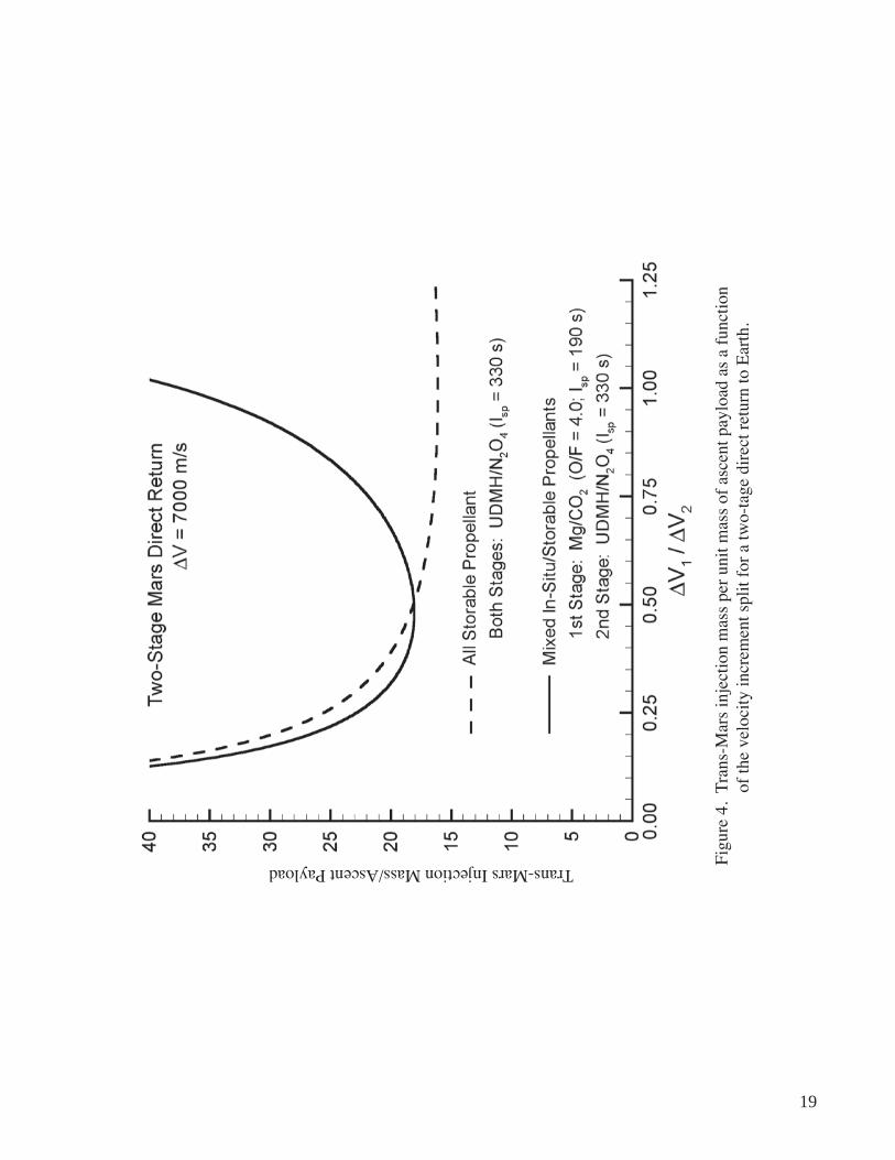
4 Trans-Mars injection mass per unit mass of ascent payload as a function of the velocity increment split for a two-stage direct return to Earth ..................................... 19
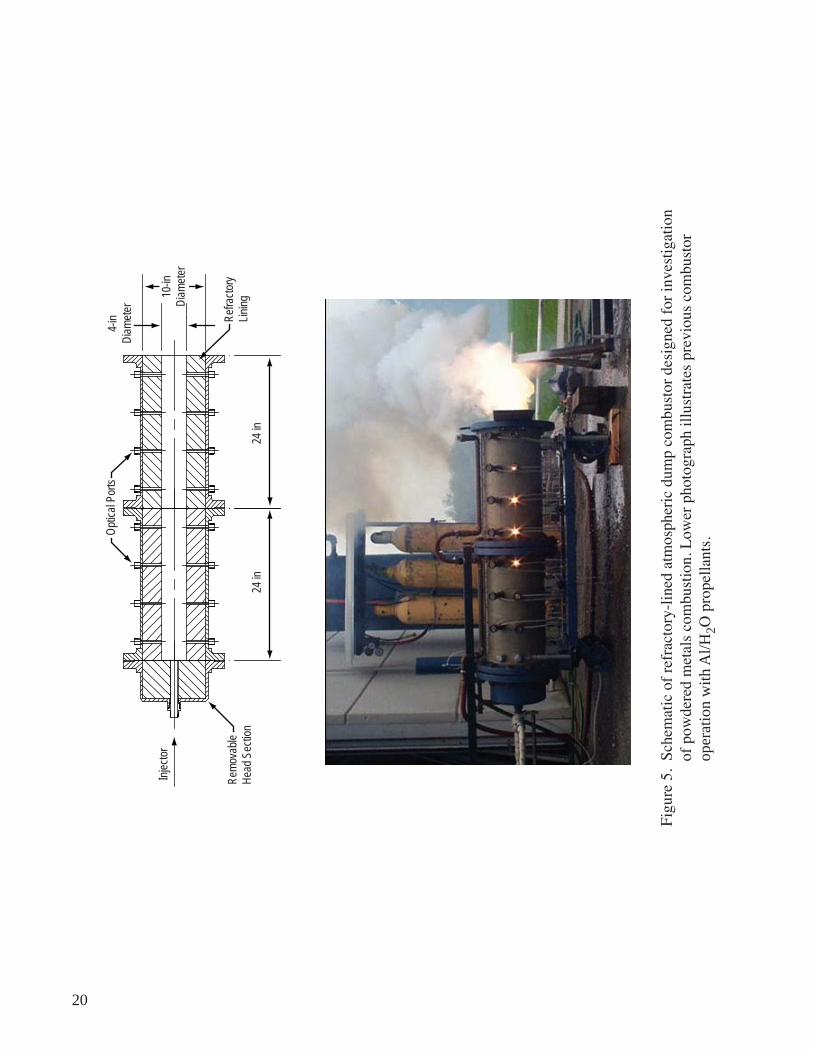
5. Schematic of refractory-lined atmospheric dump combustor designed for investigation of powdered metals combustion. Lower photograph illustrates prev�ous combustor operat�on w�th Al/H2O propellants .................................................... 20
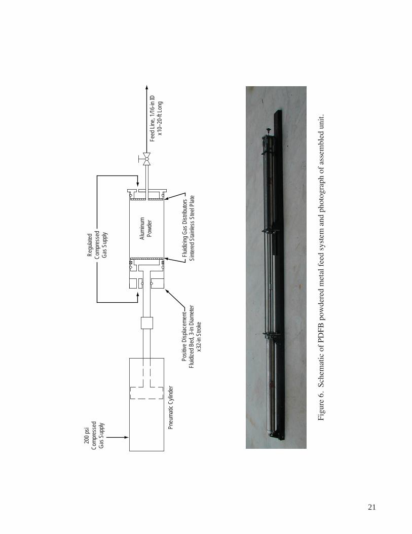
6. Schematic of PDFB powdered metal feed system and photograph of assembled unit ...... 21
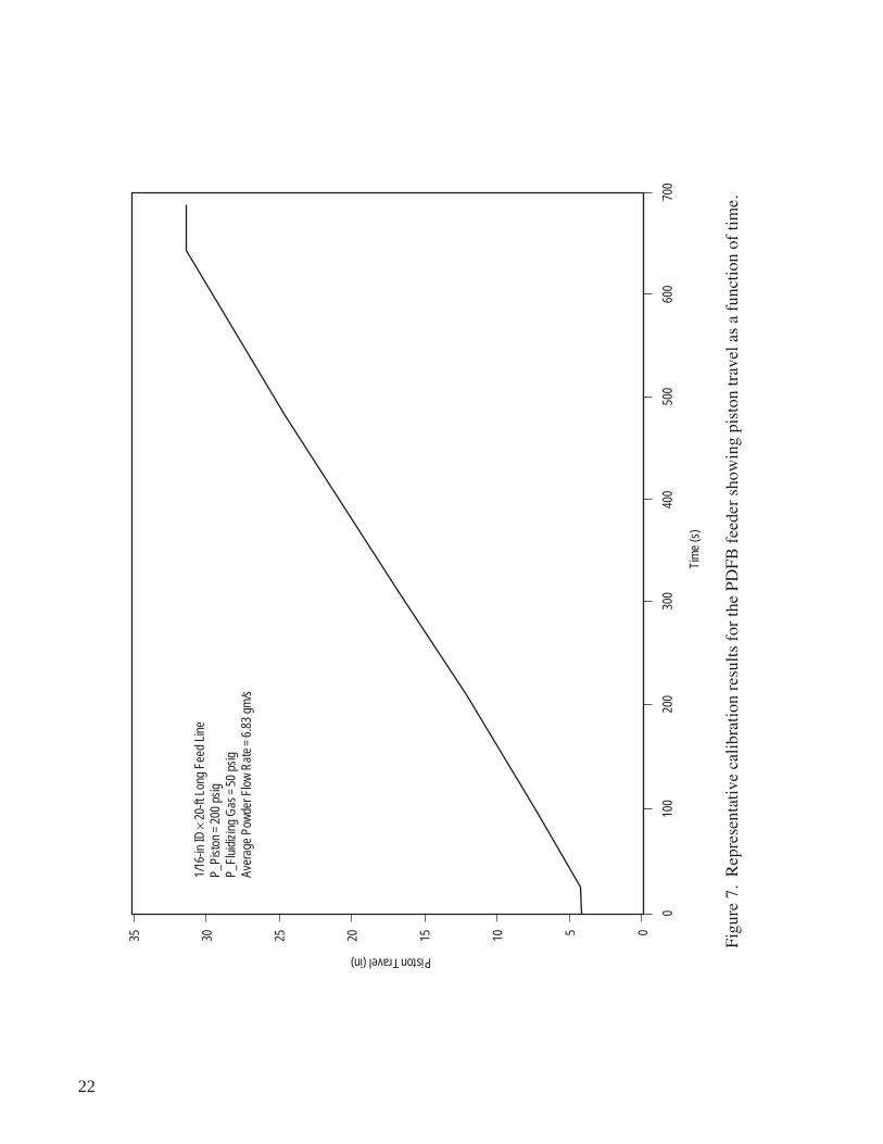
7. Representative calibration results for the PDFB feeder showing piston travel as a funct�on of t�me ........................................................................................................... 22
8. Representative calibration results for the PDFB feeder showing feed line pressure drop as a function of flow rate ............................................................................................ 23
9. Conceptual design of powdered metal injector for Mg/CO2 research combustor ............. 24
10. Photograph of main injector through burner bore following extended operat�on w�th Al and steam ............................................................................................... 25
11. Process and instrumentation diagram for Mg/CO2 research combustor operat�on ............ 26
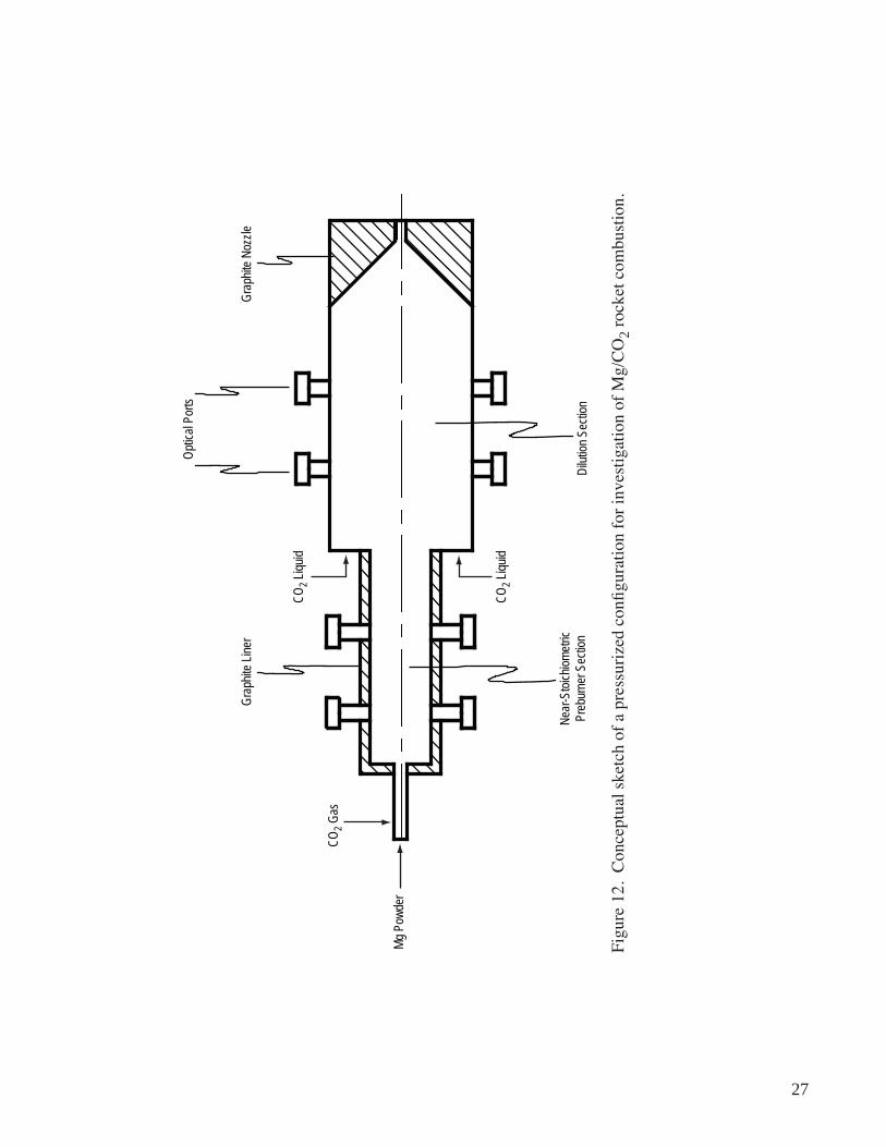
12. Conceptual sketch of a pressurized configuration for investigation of Mg/CO2 rocket combustion ............................................................................................... 27
v
lIST of TableS
1. Baseline two-stage ascent vehicle performance ................................................................... 14
2. In situ two-stage ascent vehicle performance ....................................................................... 15
v�
lIST of aCRonYMS anD SYMbolS
Al alum�num
Al2O3 aluminum oxide
Ar argon
B boron
B2H6 d�borane
B2O3 boron oxide
Be beryllium
BeH2 beryll�um hydr�de
C3H8 propane
Ca calc�um
CO carbon monoxide
CO2 carbon dioxide
H2O water
ISRU in situ resource utilization
Kr krypton
Li lithium
LOX liquid oxygen
MEPAG Mars Exploration Program Analysis Group
Mg magnes�um
v��
lIST of aCRonYMS anD SYMbolS (ConTInUeD)
MgH2 magnes�um hydr�de
MgO magnesium oxide
MSFC Marshall Space Fl�ght center
MSR Mars sample return
N2 n�trogen
N2O4 nitrogen tetroxide
Ne neone
O2 oxygen
O3 ozone
PDFB positive displacement fluidized bed
S� s�l�con
S�H4 s�lane
SiO2 silicon dioxide
T� t�tan�um
UDMH unsymmetrical dimethylhydrazine
Xe xenon
Z zirconium
v���
noMeMClaTURe
Isp specific impulse
mCO2 first-stage carbon dioxide mass
md1 first-stage dry mass
md2 second-stage dry mass
mex mass of CO2 extraction system
mf1 first-stage propellant mass
mf2 second-stage propellant mass
mMg first-stage magnesium mass
mp payload mass
mtmi trans-Mars injection mass
O/F oxidizer-to-fuel mixture ratio
t t�me
Ve,i exhaust velocity for the ith stage
DVi veloc�ty �ncrement for the �th stage
DV1 first-stage velocity increment
DV2 second-stage velocity increment
ε structural coefficient
1
TECHNICAL PUBLICATION
PoWDeReD MaGneSIUM—CaRbon DIoXIDe RoCkeT CoMbUSTIon TeChnoloGY foR In SITU MaRS PRoPUlSIon
1. InTRoDUCTIon
It is widely recognized that sustained, long-term exploration of Mars will be highly dependent upon in situ resource utilization (ISRU) technologies.1–3 Most martian ISRU concepts focus on propel-lant production techniques and compatible propulsion devices that would enable both long-range surface mobility and planetary ascent. These concepts typically involve processing of the martian atmosphere, the composition of which has been well established through prior landing missions. The composition of the lower atmosphere, as deduced from Viking lander measurements, is as follows: 95.32 percent carbon dioxide (CO2), 2.7 percent nitrogen (N2), 1.6 percent Argon (Ar), 0.13 percent oxygen (O2), 0.07 percent carbon monoxide (CO), and 0.03 percent water (H2O), with trace amounts of neon (Ne), krypton (Kr), xenon (Xe), and ozone (O3).
The predominance of CO2 in the atmosphere has led to several intriguing possibilities. One long-stand�ng suggest�on has been to transport a small chem�cal process�ng plant to Mars for the manufacture of methane and O2 from in situ CO2 and H2O resources.4 A var�at�on on th�s scheme, wh�ch avo�ds the need to extract H2O from the arid martian environment, would require transporting a small feedstock of hydrogen from Earth for the production of methane and water in a Sabatier reactor.5 The O2 requ�red for methane combust�on would be der�ved from electrolys�s of the manufactured H2O.
Implementation of such an approach, although fundamentally sound, would be extremely chal-lenging from an engineering perspective, primarily due to the difficulties encountered with long-term storage and deep space transport of hydrogen. Moreover, the power required to produce and liquefy cryogenic O2 and methane would likely be prohibitive under most mission scenarios.
A more contemporary approach to martian ISRU focuses on the production of CO and O2 d�rectly from the atmosphere via a zirconia electrolyzer, which requires no feedstock material. In this case, CO could be burned directly with liquid oxygen (LOX) yielding a specific impulse (Isp) around 290 seconds. Alternatively, the LOX could be burned with methane delivered from Earth as a means of achieving higher propulsion performance. Despite these potential advantages, zirconia electrolyzer technology remains a risky proposition for most Mars mission scenarios. For instance, the devices must operate at very high temperatures (>1,000 K), consume prodigious amounts of power, and have yet to demonstrate a high level of reliability.
In cons�der�ng the var�ous alternat�ves, �t should be noted that any approach based on �n s�tu chem�-cal processing faces a critical dilemma. That is, production of meaningful quantities of propellant during a
2
time-limited mission often leads to prohibitive surface power requirements; whereas, lowering propellant production rates to obtain more practical surface power levels can greatly extend mission duration (more than a year in most cases) and raises major reliability concerns.
A conceptually simpler approach would be to burn CO2 directly as an oxidizer with some suitably energetic fuel, which could be delivered from Earth.6–19 For bipropellant rocket applications, it would only be necessary to collect and liquefy the CO2, thereby avoiding the major complications encountered with chemical processing plants. For the special case of an endoatmospheric propulsion system such as a ramjet, the imported fuel could be injected and burned directly with the resident CO2.
The use of CO2 as an oxidizing agent may appear counterintuitive, but there are certain fuels that can remove the bound oxygen with a substantial release of energy. The most promising candidates are met-als and their hydrides and mixtures with hydrogen compounds. Shafirovich et al. have evaluated the equi-librium thermodynamic rocket performance of a wider range of these candidates including lithium (Li), beryllium (Be), boron (B), magnesium (Mg), aluminum (Al), silicon (Si), calcium (Ca), titanium (Ti), zirconium (Z), beryllium hydride (BeH2), magnesium hydride (MgH2), diborane (B2H6), and silane (SiH4).11,15 The results of these calculations, based on a chamber pressure of 10 atm and expansion to an ambient pressure of 0.01 atm, showed that the most promising fuels were Be, BeH2, Al, and Mg. Thermo-dynamic equilibrium rocket performance calculations by the authors, as shown in figure 1 for representa-tive fuels, confirm these predictions.
Beryllium and its hydride yielded the highest theoretical Isp, but the pract�cal v�ab�l�ty of these propellants is dubious due to extreme toxicity and unknown combustion characteristics. Al, Li, and B all had h�gher Isps than Mg for large oxidizer-to-fuel mass ratios, but are known to have poor ignitability char-acteristics and low combustion rates. Combustor slagging would also be more severe when burning Al due to the lower melting point of aluminum oxide (Al2O3) (2,315 K) compared to magnesium oxide (MgO) (3,098 K). As a result, Shafirovich et al. concluded that Mg was the most promising metal fuel for an engine utilizing CO2 as an oxidizer, despite its relatively poor theoretical Isp (220 s peak).11,15 It �s read�ly ignitable in CO2 at a relatively low temperature (around 1,000 K), exhibits a rapid combustion rate, and is known to burn to near completion when in particle form. As a means of improving performance while retaining these favorable characteristics, Shafirovich suggests that Mg/Al alloys should be investigated as a potential fuel as well.
These theoretical performance calculations also show that some liquid hydrides, such as B2H6 and S�H4, could serve as viable energetic fuels for CO2 combustion, a point of significant practical importance since they could be injected and burned in a conventional bipropellant rocket configuration. This simplifi-cation in engine design led Zubrin to propose B2H6 as a fuel for a Mars ascent rocket.14 However, a poten-tial difficulty with this propellant combination is the high mass fraction of condensed phase combustion products and the result�ng �mpact on Isp performance. Moreover, the condensed-phase boron oxide (B2O3) is in liquid form, introducing a potential risk for slag formation in the throat region.
However, for S�H4 combustion with CO2, the mass fract�on of condensed phase products �s much lower and the Isp performance falls between Mg and B2H6. The largest contributor to the condensed phase mass loading in this case is silicon dioxide (SiO2), which forms only inside the combustion chamber.
3
Therefore, S�H4 fuel does not suffer nozzle condensation performance penalties and is apparently more attractive than B2H6, desp�te �ts lower theoret�cal Isp. Although SiH4 is toxic and its ignitability and com-bustion characteristic with CO2 are unknown, it is stable and storable and should be retained as a potential fuel candidate pending the acquisition of reliable combustion data.15
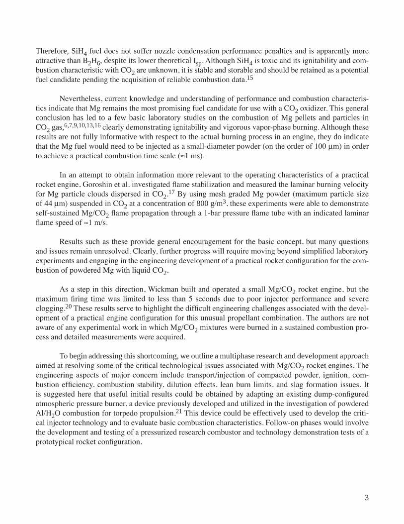
Nevertheless, current knowledge and understanding of performance and combustion characteris-tics indicate that Mg remains the most promising fuel candidate for use with a CO2 oxidizer. This general conclus�on has led to a few bas�c laboratory stud�es on the combust�on of Mg pellets and part�cles �n CO2 gas,6,7,9,10,13,16 clearly demonstrating ignitability and vigorous vapor-phase burning. Although these results are not fully �nformat�ve w�th respect to the actual burn�ng process �n an eng�ne, they do �nd�cate that the Mg fuel would need to be injected as a small-diameter powder (on the order of 100 µm) in order to achieve a practical combustion time scale (≈1 ms).
In an attempt to obta�n �nformat�on more relevant to the operat�ng character�st�cs of a pract�cal rocket engine, Goroshin et al. investigated flame stabilization and measured the laminar burning velocity for Mg particle clouds dispersed in CO2.17 By using mesh graded Mg powder (maximum particle size of 44 µm) suspended in CO2 at a concentrat�on of 800 g/m3, these experiments were able to demonstrate self-sustained Mg/CO2 flame propagation through a 1-bar pressure flame tube with an indicated laminar flame speed of ≈1 m/s.
Results such as these provide general encouragement for the basic concept, but many questions and issues remain unresolved. Clearly, further progress will require moving beyond simplified laboratory experiments and engaging in the engineering development of a practical rocket configuration for the com-bustion of powdered Mg with liquid CO2.
As a step in this direction, Wickman built and operated a small Mg/CO2 rocket engine, but the maximum firing time was limited to less than 5 seconds due to poor injector performance and severe clogging.20 These results serve to highlight the difficult engineering challenges associated with the devel-opment of a practical engine configuration for this unusual propellant combination. The authors are not aware of any experimental work in which Mg/CO2 mixtures were burned in a sustained combustion pro-cess and detailed measurements were acquired.
To beg�n address�ng th�s shortcom�ng, we outl�ne a mult�phase research and development approach aimed at resolving some of the critical technological issues associated with Mg/CO2 rocket engines. The engineering aspects of major concern include transport/injection of compacted powder, ignition, com-bustion efficiency, combustion stability, dilution effects, lean burn limits, and slag formation issues. It is suggested here that useful initial results could be obtained by adapting an existing dump-configured atmospheric pressure burner, a device previously developed and utilized in the investigation of powdered Al/H2O combustion for torpedo propulsion.21 Th�s dev�ce could be effect�vely used to develop the cr�t�-cal injector technology and to evaluate basic combustion characteristics. Follow-on phases would involve the development and testing of a pressurized research combustor and technology demonstration tests of a prototypical rocket configuration.
4
2. MISSIon ReleVanCe
It is of interest to consider the mission relevance of Mg/CO2 propulsion in some detail. The most near term mission that could potentially utilize this particular in situ technology would be a Mars sample return (MSR), a highly ranked science priority with profound implications for planetary geology and biol-ogy. To increase the scientific return and enhance the odds for obtaining samples of special significance, it should be noted that NASA’s Mars Exploration Program Analysis Group (MEPAG) has recommended that an MSR mission should include modest mobility in order to ensure access to diverse samples and sedimentary deposits at a site known to be scientifically compelling.
It is anticipated that the MSR mission will require several descent-ascent vehicles or a rover that can traverse hundreds of kilometers about the landing site. However, inclusion of this mobility require-ment can increase launch payload mass to impractical levels, making the mission nonviable with existing technology. As an alternative, in situ propellant production and utilization should be examined as a pos-sible means of circumventing this limitation.
For instance, Zubrin has recommended a ballistic descent-ascent vehicle/hopper utilizing a nuclear thermal engine that could process CO2 propellant.22 The bas�c �dea would be to hop from s�te to s�te by refilling the propellant tank with liquid CO2 after every landing. The final fill would then be used to boost a sample return module into Mars rendezvous orbit or directly into a minimal energy orbit to Earth.
Alternatively, Shafirovich et al.11,12 recommend consideration of Mg/CO2 rocket propulsion for the descent-ascent vehicle/hopper, as illustrated in figure 2. In this case, the Mg fuel transported from Earth may have less mass than a nuclear reactor with radiation shielding. These studies estimate that about 2 tons of storable unsymmetrical dimethylhydrazine (UDMH)/nitrogen tetroxide (N2O4) propellant would need to be transported from Earth for the surface-to-orbit ascent of a vehicle having a final mass of 1 ton. An Mg/CO2 engine operating with a CO2/Mg mass ratio of 4 (Isp = 190 s) would require 5.55 tons of propellant, but only 1.11 tons of this total would need to be transported from Earth. The real gain could be less if the final mass of the vehicle increased.
We briefly examine this issue by considering a two-stage Mars ascent vehicle in which the first boost stage uses either Mg/CO2 propellant or UDMH/N2O4 storable propellant. The second upper stage is always considered to use UDMH/N2O4 storable propellants. We assume a surface stay time of 500 days and include the required mass for CO2 extraction equipment.
Application of the rocket equation, including a structural coefficient (ε) to account for the dry we�ght of the stages, y�elds the follow�ng relat�on for the upper stage propellant mass per un�t mass of ascent payload:
mm
e
ef
p
V V
V V
e
e2
2 2
2 2
1 1=−
−
−( )−
−
∆
∆
,
,.
εε (1)
5
This equation can then be used to obtain a similar expression for the boost stage propellant mass per unit mass of ascent payload:
mm
e
ef
p
V V
V V
e
e1
2 2
2 2
1 1=−
−
+
−
−
∆
∆
,
, ε
−
−
−( )−
−1 1
1 1
1 1
e
e
V V
V V
e
e
∆
∆
,
,.
εε (2)
Here, DVi �s the veloc�ty �ncrement for the �th stage and Ve,i is the exhaust velocity for ith stage. These results can be used to deduce the dry mass of each stage per un�t mass of ascent payload accord�ng to the standard definition of the structural coefficient
mm
mm
mm
d
p
f
p
d
p
1 1 2
1 1=
−
=−
εε
εε
mm
f
p
2 . (3)
The relative amounts of Mg and CO2 in the boost stage depends on the oxidizer-to-fuel mixture ratio (O/F)
mm O F
mm
mm
O FO F
Mg
p
f
p
CO
p=
−
=−
11 1
1 2
mm
f
p
1 . (4)
To estimate the mass of the CO2 extraction equipment, we consider a solar powered adsorption compressor.23 Following a similar approach by Shafirovich, we assume that this type of acquisition unit can produce 0.1 kg of CO2 per unit mass of the acquisition unit per day.24 Because the specific power of this CO2 extraction unit is roughly equal to that of a martian solar power plant (≈15 W/kg), we deduce that the mass of the complete CO2 extraction system per unit mass of collected CO2 �s
m
m tex
CO2
10 05
=.
, (5)
where t is the collection time in days. It follows that the mass of the CO2 extraction equipment per unit mass of ascent payload �s g�ven by
mm t
O FO F
mm
ex
p
f
p=
−
10 05 1
1
.. (6)
A good parameter of merit for this mission is the trans-Mars injection mass (mtmi) per unit mass of ascent payload, which may be expressed in the form:
mm
mm
mm
mm
mm
mm
tmi
p
ex
p
Mg
p
d
p
f
p
d
p= + + + + +1 2 2 1 . (7)
6
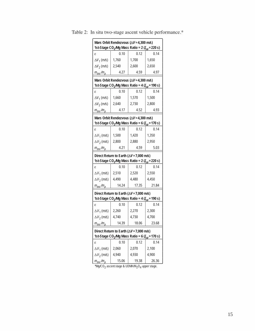
By specifying the ε, the total maneuver velocity increment, and the exhaust velocity for each stage, this parameter can now be evaluated as a function of the velocity increment split between stages. Here, we examine both Mars orbit rendezvous (DV = 4,300 m/s) and direct minimum energy return to Earth (DV = 7,000 m/s) assuming CO2/Mg mass ratios of 2 (Isp = 220 s), 4 (Isp = 190 s), and 6 (Isp = 170 s) and structural coefficients of 0.10, 0.12, and 0.14. Representative results are shown in figure 3 (Mars orbit rendezvous) and figure 4 (direct Mars return) for a CO2/Mg mass rat�o of 4, w�th ε = 0.1 for all stages. Note the occurrence of an opt�mum DV spl�t between stages to obta�n a m�n�mum value for the mtmi. These results demonstrate that the �n s�tu boost stage prov�des a sl�ght advantage for ascent to Mars orb�t but leads to an inferior system for direct return to Earth. In the latter case, the poor Isp of the �n s�tu propellant translates into excessive Mg and structural mass for the boost stage. Note that the optimum DV spl�t occurs when about 20 percent of the total velocity increment is provided by the Mg/CO2 boost stage.
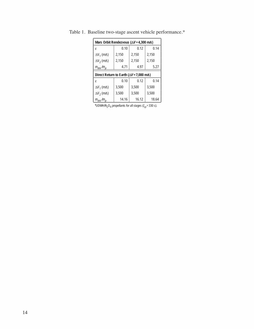
The baseline performance characteristics for two-stage systems with all storable propellant are listed in table 1. The optimal performance results for two-stage systems using Mg/CO2 for boost-stage propulsion are summarized in table 2. From this data, we observe that the optimal CO2/Mg mass rat�o �s about 4 and that the maximum mtmi sav�ngs �s somewhat less than 12 percent when ascend�ng to a Mars orbit rendezvous, assuming equal structural coefficients for all stages. When ascending directly into an Earth return orbit, the in situ system is unable to provide any mass savings under any operating condi-tions.
The preceding analysis assumes a simple grab-and-go MSR mission that requires no mobility for sample procurement. Thus, the vehicle is only required to land and ascend once, and in situ propellant utilization yields no significant mass savings over conventional storable propellants transported entirely from Earth. In this case, there is little incentive to take on the additional risks associated with new vehicle architecture. However, it has been argued that an ISRU architecture should remain in consideration for the purpose of demonstrating the technology and preparing infrastructure for long-term sustained exploration of Mars.19
As the need for mob�l�ty �ncreases, the mass sav�ngs of the �n s�tu arch�tecture becomes more substantial and beneficial. Detailed analyses by Shafirovich et al. have shown that a Mars descent-ascent vehicle that undertakes two to three ballistic hops with interhop CO2 refills before the final ascent to orbit has a clear mass savings over conventional storable propellants.11,12,24
In situ propellant and utilization technologies will be even more essential from a longer term explo-ration perspective. Light metals and elements are generally abundant in the crust of terrestrial planets, and methods for processing the planetary regolith and extracting these elements appear feasible. Therefore, burning of metals with indigenous oxidizers may have broad applicability across the solar system and warrants further technological development.
7
3. RoCkeT enGIne ConfIGURaTIon ISSUeS
The practical question of how to configure and design an Mg/CO2 rocket remains an open issue. Several alternat�ve eng�ne des�gn concepts have been suggested, but rud�mentary evaluat�on and eng�neer-ing judgment leans heavily toward direct injection of powdered Mg and CO2 in a bipropellant engine.11,17 This conclusion is largely motivated by the favorable combustion characteristics of Mg particles in CO2, as observed and confirmed in previous laboratory experiments.
For instance, data from these experiments indicate that the minimum ambient temperature for particle ignition is very close to the melting point of Mg (≈1,000 K), implying easy engine ignitability. Furthermore, these experiments confirm the existence of two spatially separated chemical reaction zones in which Mg + CO2 → MgO + CO within a gas phase region displaced from the particle surface, while Mg + CO → MgO + C occurs, essentially heterogeneously, near the particle surface. As a result, Mg particles undergo vigorous vapor-phase burning in CO2, which leads to an expectation of high engine combustion efficiency.
The pr�mary eng�neer�ng challenge of th�s type of eng�ne appears to be the development of a rel�-able and effective transport/injection system for metal powder. Such a system must be capable of pumping, injecting, and dispersing Mg powder in a fluid-like manner without jamming or clogging. The consensus view on this matter is that a pneumatic feed system based on fluidization techniques represents the most prom�s�ng technolog�cal opt�on for th�s type of eng�ne, an op�n�on supported by the authors’ own �nformed experience with similar devices. An additional simplification resulting from this approach is that the Mg powder may be utilized in the same state in which it is stored and transported to Mars as a dry compacted powder.
8
4. ReSeaRCh anD DeVeloPMenT aPPRoaCh
Since the ultimate objective is to develop a practical Mg/CO2 rocket engine and since basic feasi-bility issues have been more or less resolved through simplified laboratory experiments, we suggest that the most appropriate strategy is to proceed with the development of a practical engine configuration. In th�s way, �t w�ll be poss�ble to beg�n address�ng the �mportant eng�neer�ng aspects of a powdered metal combustion device such as transport/injection of compacted powder, ignition, combustion efficiency, combustion stability, dilution effects, lean burn limits, and slag formation issues.
Along these l�nes, we recommend a mult�phase research and development approach a�med at resolv-ing critical technical issues in a cost effective manner. For example, useful initial results could be obtained by adapting an existing dump-configured atmospheric pressure burner, a device previously developed and utilized in the investigation of powdered Al/H2O combustion for torpedo propulsion.21 W�th some s�mple low-cost modifications, this device could be readily modified to serve as a test bed for the development of a fluidized-bed powdered metal transport system and for evaluation of basic combustion characteristics. Follow-on phases would involve the development and testing of a pressurized research combustor and technology demonstration tests of a prototypical rocket configuration.
4.1 Phase I Atmospheric Pressure Burner Configuration
The basis for phase I development activities is an existing refractory-lined, atmospheric-pressure dump combustor designed for investigation of powdered Al combustion with steam. This device, shown schematically in figure 5, is currently being installed in the NASA Marshall Space Flight Center (MSFC) Propulsion Research Laboratory, and modifications are being implemented for conversion to Mg/CO2 operation.
The combustion chamber consists of a 4-in diameter circular passage with a 3-in thick high- alumina, heavy-castable, refractory lining inside of two 24-in sections of 10-in diameter carbon steel pipe. Eight sets of diametrically opposed ports are distributed at 6-in intervals along the combustor axis for opti-cal access and extraction of combustion product samples. The combustor is cooled by running water over an external wick and has a removable head section to simplify cleanout of deposits between test runs.
Powdered metal and gaseous oxidizer are injected through a central annular injector. The pow-der is supplied to the injector as a fluidized stream using a small quantity of inert carrier gas and enters the combustion chamber with the gaseous oxidizer through an annular injector. A portion of the oxidizer may be injected through an annular shroud surrounding the injector tube to reduce premature melting of the �ncom�ng fuel part�cles and bu�ldup of rec�rculated condensed phase combust�on products at the injector exit.
For illustrative purposes, figure 5 also includes a photograph of the device in operation with Al/H2O propellants. This particular propellant combination required significant combustor preheating to promote ignition; but, once started, stable and efficient combustion could be maintained for an extended
9
duration (several minutes) without difficulty and without injector clogging. Because the ignition tem-perature is lower for Mg particles in CO2 than for Al part�cles �n H2O and because burning rates of Mg particles are faster in CO2 than for similar sized Al particles in H2O, it is highly probably that a practical Mg/CO2 combustor can eventually be developed.
A metal powder feed system that can supply a steady, repeatable flow of fuel to the combustor is a critical component for any metal powder rocket engine. As part of the previous Al/H2O combustor devel-opment activities, a Positive Displacement Fluidized Bed (PDFB) feeder was designed, developed, and successfully demonstrated. The PDFB concept was originated at Bell Aerospace during the late 1960s in an attempt to supply powdered metal fuels to rocket and missile combustors.25,26
In the PDFB system, metal powder is contained in a pneumatic cylinder with porous metal plates on the head and on the piston face. Fluidizing gas is supplied through the porous plates while the piston is used to maintain uniform powder density at the feed line inlet as powder is being removed. Previous experience indicates that this type of system can supply a steady and stable stream of powdered metal to a combustion chamber with a high degree of reliability.
Our PDFB system was constructed by modifying a standard 3-in diameter × 32-in stroke stainless steel pneumatic cylinder. Porous metal plate distributors for fluidizing gas were added in the piston face and at the discharge, and the piston seal was modified to keep it from binding on the Al particles. A sepa-rate 3-in diameter pneumatic cylinder supplies the force needed to maintain uniform density in the pow-der. A schematic of this PDFB system is provided in figure 6 along with a photograph of the assembled unit.
During testing of the feeder system with 17-µm mean d�ameter spher�cal Al part�cles, �t was found that smooth and repeatable flow rates in the range of 5–10 g/s could be supplied through a 1/16-in inside d�ameter × 20-ft long dense phase-feed line with feed line pressure drops ranging from 40–100 psi. Reli-able flow was achieved flowing into both atmospheric and pressurized receivers.
Representative calibration results for the PDFB feeder are summarized in figures 7 and 8. Figure 7 shows a typical result for PDFB piston displacement as a function of time, which clearly demonstrates the achievement of steady and stable powder flow. Figure 8 summarizes the correlation with feed line pressure drop for a wide range of powder flow rates.
As part of the combustor modifications for Mg/CO2 operation, a new powdered metal injector is being sized, designed, and fabricated. The fundamental design configuration for the Mg/CO2 injection system follows a conceptual approach previously established during burner operations with Al and steam. The basic conceptual design is illustrated in figure 9 where powdered metal is introduced to a mixing chamber through a central tube surrounded by two annular injectors for oxidizer and propane (C3H8), which serves as an ignition and flame stabilization source. The mixing tube feeds into the main dump combustor and is shrouded by an annular bypass injector for the oxidizer. During previous burner opera-t�ons w�th Al and steam, the annular shroud was found to be an effect�ve means of prevent�ng slagg�ng and clogging in the main injector. This capability is illustrated in figure 10, which shows a photograph of the main injector through the burner bore following extended operation with Al and steam. Note that the injector ports are clear and free of any residue.
10
Following modifications of this apparatus for Mg/CO2 operation, experiments are planned to deter-mine how variations in particle size, fuel flow rate, and O/F impact combustion efficiency and stability. A process and instrumentation diagram for these experiments is shown in figure 11. The start-up proce-dure is to first introduce a C3H8/O2 pilot flame into the combustor. Then, Mg powder flow is started and C3H8 flow is stopped. At this point, the O2 flow may be slowly reduced until the combustor is sufficiently warmed to support unaided Mg/CO2 combustion. Detailed combustion performance measurements could then be implemented.
Subsequent experiments would determine the range of stable combustion and required residence times for Mg/CO2 mixtures for different particle sizes and O/Fs. Flame radiation characteristics, including temperature and spectral �ntens�ty, would be measured and evaluated, and combust�on product samples would be extracted and analyzed to acquire information on combustion efficiency. As part of this experi-mental test�ng, �t �s also h�ghly recommended that a parallel computat�onal analys�s capab�l�ty be devel-oped and validated. This activity would be essential for interpreting the experimental data, understanding device operation, and for perfecting engine design to obtain optimal performance attributes.
At the conclusion of the phase I effort, hardware required for practical rocket engine operation would be developed and proven, particularly the metal powder feed system and injector. Moreover, the technical feasibility of the engine concept would be convincingly demonstrated, and sufficient engineer-ing data and adequate analysis tools would exist to support the design and development of a pressurized combustor configuration in a follow-on phase II effort.
4.2 Phase II Pressurized Combustor Configuration
In the follow-on phase II effort, data from the phase I atmospheric pressure tests would be used to design a pressurized combustor that could operate in the pressure range of interest for practical rocket applications. It has been suggested that a Mars ascent rocket should operate at a chamber pressure in the range of 10 atm, since this would allow an expansion ratio PC/PE = 1,000 at Mars surface pressure (about 10 mbar) and would also be low enough to allow the CO2 oxidizer to be pressure-fed.
The preliminary concept for the pressurized combustor would employ a fuel-rich preburner section followed by a dilution section, where additional CO2 would be added to raise the overall O/F to the range of 4 to 6. The combustion chamber would have a linear configuration with a water-cooled metal jacket and graphite liner, as illustrated by the conceptual sketch in figure 12. Optical ports would be installed along the combustor axis, and experiments similar to those planned for the atmospheric combustor would be conducted. Computational analysis tools would also be refined and validated as part of this broad-based technology development effort.
4.3 Phase III Prototypical Rocket Configuration
The results of the phase II pressurized combustor experiments would provide the engineering data required for the design of a phase III prototype rocket engine. The purpose of this effort would be to dem-onstrate a flight-like engine configuration including all major components and subsystems. Tests with this engine would fully demonstrate the technology in a relevant fashion as a risk reduction activity leading to a mission application.
11
5. ConClUSIonS
Powdered Mg combustion with CO2 has been examined as a potential in situ propellant combina-tion for Mars propulsion and power. Mission analyses indicate that this combination can have merit over storable bipropellants transported from Earth despite its relatively poor propulsion performance. This advantage becomes more pronounced as surface mobility requirements increase.
Basic laboratory studies have established proof of principle, and it is recommended that further progress will require the development of practical combustor configurations. A multiphase research and development strategy has been outlined as a cost-effective approach to technology maturation. It is argued that this strategy could be initially implemented by adapting an existing atmospheric pressure-dump com-bustor, previously developed for investigation of powdered Al combustion with steam. This would permit the establ�shment of bas�c eng�neer�ng feas�b�l�ty wh�le address�ng fundamental eng�neer�ng aspects of a practical engine design. Follow-on phases would involve the development and testing of a pressurized research combustor and technology demonstration of a prototype rocket engine.
12
RefeRenCeS
1. French, J.R.: “Some Unconventional Approaches to the Exploration of Mars,” Spaceflight, Vol. 33, No. 2, pp. 62–66, 1991.
2. Linne, D.L.; and Meyer, M.L.: “A Compilation of Lunar and Mars Exploration Strategies Utilizing Indigenous Propellants,” NASA TM 105262, January 1992.
3. French, J.R.: “Concepts for In-Situ Resource Utilization on Mars: A Personal Historical Perspective,” Journal of the British Interplanetary Society, Vol. 48, No. 7, pp. 311–313, October 1995.
4. Ash, R.L.; Dowler, W.L.; and Varsi, G.: “Feasibility of Rocket Propellant Production on Mars,” Acta Astronautica, Vol. 5, pp. 705–724, 1978.
5. Zubrin, R.M.; and Baker, D.: “Humans to Mars in 1999,” Aerospace America, Vol. 28, No. 8, pp. 30–32, 1990; see also “Mars Direct,” Ad Astra, Vol. 2, No. 11, pp. 33–34, 1990.
6. Rhein, R.A.: “The Combustion of Powdered Metals in Nitrogen and Carbon Dioxide,” Pyrodynamics, Vol. 3, No. 2, 1965, pp. 161–168, 1965.
7. Yuasa, S.; and Isoda, H.: “Ignition and Combustion of Metals in a Carbon Dioxide Stream,” 22nd Symposium (International) on Combustion, The Combustion Institute, pp. 1635–1641, 1988.
8. Yuasa, S.; and Isoda, H.: “Carbon Dioxide Breathing Propulsion for a Mars Airplane,” AIAA Paper 89–2863, 1989.
9. Yuasa, S.; and Fukuchi, A.: “Ignition and Combustion of Magnesium in Carbon Dioxide Streams,” 25th Symposium (International) on Combustion, The Combustion Institute, pp. 1587–1594, 1994.
10. Shafirovich, E.Ya.; and Goldshleger, U.I.: “Combustion of Magnesium Particles in CO2/CO Mixtures,” Combust. Sci. and Tech., Vol. 84, pp. 33–43, 1992.
11. Shafirovich, E.Ya.; Shiryaev, A.A.; and Goldshleger, U.I.: “Magnesium and Carbon Dioxide: A Rocket Propellant for Mars Missions,” Journal of Propulsion and Power, Vol. 9, No. 2, pp. 197–203, 1993.
12. Shafirovich, E.Ya.; Shiryaev, A.A.; and Goldshleger, U.I.: “Mars Multi-Sample Return Mission,” Journal of the British Interplanetary Society, Vol. 48, pp. 315–319, 1995.
13. Shafirovich, E.Ya.; Shiryaev, A.A.; and Goldshleger, U.I.: “Combustion of Magnesium Particles in Carbon Dioxide and Monoxide,” AIAA Paper 95–2992, 1995.
14. Zubrin, R.M.: “Diborane/CO2 Rockets for Use in Mars Ascent Vehicles,” Journal of the British Interplanetary Society, Vol. 48, pp. 387–390, 1995.
13
15. Shafirovich, E.Ya.; and Goldshleger, U.I.: “Comparison of Potential Fuels for Martian Rockets Using CO2,” Journal of Propulsion and Power, Vol. 13, No. 3, pp. 395–397, 1997.
16. Legrand, B.; Shafirovich, E.Ya.; Marion, M.; Chaureau, M.; and Goelkalp, I.: “Ignition and Combus- tion of Levitated Magnesium Particles in Carbon Dioxide,” 27th Symposium (International) on Combustion, The Combustion Institute, pp. 2413–2419 1998.
17. Goroshin, S.; Higgins, A.J.; and Lee, J.H.S.: “Powdered Magnesium Carbon Dioxide Propulsion Concepts for Mars Missions,” AIAA Paper 99–2408, 1999.
18. Linnell, J.A.; and Miller, T.F.: “A Preliminary Design of a Magnesium Fueled Martian Ramjet Engine,” AIAA Paper 2002–3788, 2002.
19. Ismail, A.M.: “Technology Requirements for Mars Sample Return Using CO2/Metal Powder Propel- lants,” 54th International Astronautical Congress, Paper IAC–03–Q.3.b.06, 2003.
20. Wickman, J.H.: “In-Situ Martian Rocket and Airbreathing Jet Engines,” SBIR Phase II Final Report, NASA Contract NAS8–97048, 1998.
21. Foote, J.P.; Thompson, B.R.; and Lineberry, J.T.: “Combustion of Aluminum With Steam for Under- water Propulsion,” in Advances in Chemical Propulsion, G. Roy (ed.), ISBN 0–8493–1171–3, 2002.
22. Zubrin, R.M.: “Indigenous Martian Propellant,” Aerospace America, Vol. 27, No. 8, pp. 48–51, 1989.
23. Rapp, D,; Karlman, P.B.; Clark, D.L.; and Carr, C.M.: “Adsorption Compressor for the Acquisition and Compression of Atmospheric CO2 on Mars,” AIAA Paper 97–2763, 1997.
24. Shafirovich, E.YA.; Salomon, M.; and Goelkalp, I.: “Mars Hopper Versus Mars Rover,” 5th IAA International Conference on Low-Cost Planetary Missions, ESTEC, Noordwijk, The Netherlands, September 24–26, 2003.
25. Fricke, H.D.; Burr, J.W.; and. Sobieniak, M.G.: “Fluidized Powders—A New Approach to Storable Missile Fuels,” 12th JANNAF Liquid Propulsion Meeting, CPIA Publication 201, pp. 393–411, 1970.
26. Loftus, H.J.; Montannino, L.N.; and Bryndle, R.C.: “Powder Rocket Feasibility Evaluation,” AIAA Paper 72–1162, AIAA/SAE 8th Joint Propulsion Specialist Conference, 1972.
27. Loftus, H.J.; Marshall, D.; and Montanino, L.N.: “Powdered Rocket Feasibility Evaluation,” Techni- cal Report AFRPL–TR–73–22, U.S. Air Force Rocket Propulsion Laboratory, March 1973.
28. Loftus, H.J.: “Fluidized Powder Gas Generator,” Bell Aerospace Textron, Technical Report ARMY– MSL–CMD–RH–CR–81–21, U.S. Army Missile Command, May 1981.
14
Table 1. Baseline two-stage ascent vehicle performance.*
Mars Orbit Rendezvous (DV = 4,300 m/s)
ε 0.10 0.12 0.14
DV1 (m/s) 2,150 2,150 2,150
DV2 (m/s) 2,150 2,150 2,150
mtmi /mp 4.71 4.97 5.27
Direct Return to Earth (DV = 7,000 m/s)
ε 0.10 0.12 0.14
DV1 (m/s) 3,500 3,500 3,500
DV2 (m/s) 3,500 3,500 3,500
mtmi /mp 14.16 16.12 18.64
*UDMH/N2O4 propellants for all stages (Isp = 330 s).
15
Table 2: In situ two-stage ascent vehicle performance.*
Mars Orbit Rendezvous (DV = 4,300 m/s)1st-Stage CO2/Mg Mass Ratio = 2 (Isp = 220 s)
ε 0.10 0.12 0.14
DV1 (m/s) 1,760 1,700 1,650
DV2 (m/s) 2,540 2,600 2,650
mtmi /mp 4.27 4.59 4.97
Mars Orbit Rendezvous (DV = 4,300 m/s)1st-Stage CO2/Mg Mass Ratio = 4 (Isp = 190 s)
ε 0.10 0.12 0.14
DV1 (m/s) 1,660 1,570 1,500
DV2 (m/s) 2,640 2,730 2,800
mtmi /mp 4.17 4.52 4.93
Mars Orbit Rendezvous (DV = 4,300 m/s)1st-Stage CO2/Mg Mass Ratio = 6 (Isp = 170 s)
ε 0.10 0.12 0.14
D V1 (m/s) 1,500 1,420 1,350
D V2 (m/s) 2,800 2,880 2,950
mtmi /mp 4.21 4.59 5.03
Direct Return to Earth (DV = 7,000 m/s)1st-Stage CO2/Mg Mass Ratio = 2 (Isp = 220 s)
ε 0.10 0.12 0.14
D V1 (m/s) 2,510 2,520 2,550
D V2 (m/s) 4,490 4,480 4,450
mtmi /mp 14.24 17.35 21.84
Direct Return to Earth (DV = 7,000 m/s)1st-Stage CO2/Mg Mass Ratio = 4 (Isp = 190 s)
ε 0.10 0.12 0.14
D V1 (m/s) 2,260 2,270 2,300
D V2 (m/s) 4,740 4,730 4,700
mtmi /mp 14.39 18.06 23.68
Direct Return to Earth (DV = 7,000 m/s)1st-Stage CO2/Mg Mass Ratio = 6 (Isp = 170 s)
ε 0.10 0.12 0.14
D V1 (m/s) 2,060 2,070 2,100
D V2 (m/s) 4,940 4,930 4,900
mtmi /mp 15.06 19.38 26.36 *Mg/CO2 ascent stage & UDMH/N2O4 upper stage.
16
Figu
re 1
. Id
eal r
ocke
t Isp
for t
he c
ombu
stio
n of
repr
esen
tativ
e fu
els i
n C
O2.
Res
ults
are
from
ther
mod
ynam
�c e
qu�l�
br�u
m c
alcu
lat�o
ns a
ssum
�ng
a ch
ambe
r
pres
sure
of 1
0 at
m a
nd a
noz
zle
exit
pres
sure
of 0
.01
atm
.
Spacific Impulse Isp (sec)
17
Figu
re 2
. Ill
ustra
tion
of a
Mar
s des
cent
-asc
ent v
ehic
le/h
oppe
r usi
ng M
g/C
O2 r
ocke
t pro
puls
ion.
CO
2 �s c
olle
cted
and
lique
fied
betw
een
each
land
ing
and
laun
ch e
vent
.
18
Figu
re 3
. Tr
ans-
Mar
s inj
ectio
n m
ass p
er u
nit m
ass o
f asc
ent p
aylo
ad a
s a fu
nctio
n
of th
e ve
loci
ty in
crem
ent s
plit
for a
two-
stag
e as
cent
to M
ars o
rbit.
Trans-Mars Injection Mass/Ascent Payload
19
Figu
re 4
. Tr
ans-
Mar
s inj
ectio
n m
ass p
er u
nit m
ass o
f asc
ent p
aylo
ad a
s a fu
nctio
n
of th
e ve
loci
ty in
crem
ent s
plit
for a
two-
tage
dire
ct re
turn
to E
arth
.
Trans-Mars Injection Mass/Ascent Payload
20
Opt
ical
Por
ts
Ref
ract
ory
Lini
ng
Inje
ctor
Rem
ovab
leH
ead
Sect
ion
4-in
Dia
met
er
24 in
24 in
10-in
Dia
met
er
Figu
re 5
. Sc
hem
atic
of r
efra
ctor
y-lin
ed a
tmos
pher
ic d
ump
com
bust
or d
esig
ned
for i
nves
tigat
ion
of
pow
dere
d m
etal
s com
bust
ion.
Low
er p
hoto
grap
h ill
ustra
tes p
revi
ous c
ombu
stor
oper
at�o
n w
�th A
l/H2O
pro
pella
nts.
21
200
psi
Com
pres
sed
Gas
Sup
ply
Reg
ulat
edC
ompr
esse
dG
as S
uppl
y
Feed
Lin
e, 1
/16-
in ID
x10–
20-ft
Lon
g
Alum
inum
Pow
der
Flui
dizi
ng G
as D
istri
buto
rsSi
nter
ed S
tain
less
Ste
el P
late
Posi
tive
Dis
plac
emen
tFl
uidi
zed
Bed,
3-in
Dia
met
erx3
2-in
Stro
ke
Pneu
mat
ic C
ylin
der
Figu
re 6
. Sc
hem
atic
of P
DFB
pow
dere
d m
etal
feed
syst
em a
nd p
hoto
grap
h of
ass
embl
ed u
nit.
22
010
020
030
040
050
060
070
0
Piston Travel (in)
35 30 25 20 15 10 5 0
1/16
-in ID
20-ft
Lon
g Fe
ed L
ine
P_Pi
ston
=20
0 ps
igP_
Flui
dizi
ng G
as=
50 p
sig
Aver
age
Pow
der F
low
Rat
e=
6.83
gm
/s
Tim
e (s
)
Figu
re 7
. R
epre
sent
ativ
e ca
libra
tion
resu
lts fo
r the
PD
FB fe
eder
show
ing
pist
on tr
avel
as a
func
tion
of ti
me.
23
12
34
56
78
9 10
11
Sqrt (Feed Line dp/ft), (psi/ft)0.5
2.5 2
1.5 1
0.5
Pow
der F
low
Rat
e (g
m/s
)
Figu
re 8
, R
epre
sent
ativ
e ca
libra
tion
resu
lts fo
r the
PD
FB fe
eder
show
ing
feed
line
pre
ssur
e dr
op a
s a fu
nctio
n of
flow
rate
.
24
Bypa
ssO
xidi
zer
Prop
ane
Oxi
dize
r
Met
alPo
wde
rM
ixin
g Tu
beC
ombu
stio
n C
ham
ber
Figu
re 9
. C
once
ptua
l des
ign
of p
owde
red
met
al in
ject
or fo
r Mg/
CO
2 res
earc
h co
mbu
stor
.
25
Figu
re 1
0. P
hoto
grap
h of
mai
n in
ject
or th
roug
h bu
rner
bor
e fo
llow
ing
exte
nded
ope
ratio
n
with
Al a
nd st
eam
.
26
200
psi20
0 ps
i
200
psi
200
psi
250
psi
50–1
00 p
si
5 g/
s(0
.011
lb/s
)
3.3
g/s
(0.0
07 lb
/s)
0.9
g/s
(0.0
02 lb
/s)
10%
OX
Flow
9.0–27 g/s(0.02–0.06 lb/s)
20,0
00 c
c/m
in
9,00
0 cc
/min
700
cc/m
in50
0 ps
i
50 p
si
60 p
si
450
psi
Ar B
ottle
O2 Bottle
CO2 Bottle
C3H8Bottle
Line
ar P
oten
tiom
eter
Feed
er C
ylin
der
Push
er C
ylin
der
Wat
er B
ath
Wat
er B
ath
P
P
PP
P
Figu
re 1
1. P
roce
ss a
nd in
stru
men
tatio
n di
agra
m fo
r Mg/
CO
2 res
earc
h co
mbu
stor
ope
ratio
n.
27
Opt
ical
Por
ts
Gra
phite
Noz
zle
CO
2Li
quid
Gra
phite
Lin
er
CO
2G
as
Mg
Pow
der
Nea
r-Sto
ichi
omet
ricPr
ebur
ner S
ectio
n
CO
2Li
quid
Dilu
tion
Sect
ion
Figu
re 1
2. C
once
ptua
l ske
tch
of a
pre
ssur
ized
con
figur
atio
n fo
r inv
estig
atio
n of
Mg/
CO
2 roc
ket c
ombu
stio
n.
28
REPORT DOCUMENTATION PAGE Form ApprovedOMB No. 0704-0188
Public reporting burden for this collection of information is estimated to average 1 hour per response, including the time for reviewing instructions, searching existing data sources, gathering and maintain-ing the data needed, and completing and reviewing the collection of information. Send comments regarding this burden estimate or any other aspect of this collection of information, including suggestions for reducing this burden, to Washington Headquarters Services, Directorate for Information Operation and Reports, 1215 Jefferson Davis Highway, Suite 1204, Arlington, VA 22202-4302, and to the Office of Management and Budget, Paperwork Reduction Project (0704-0188), Washington, DC 20503
1. AGENCY USE ONLY (Leave Blank) 2. REPORT DATE 3. REPORT TYPE AND DATES COVERED
4. TITLE AND SUBTITLE 5. FUNDING NUMBERS
6. AUTHORS
7. PERFORMING ORGANIZATION NAME(S) AND ADDRESS(ES) 8. PERFORMING ORGANIZATION REPORT NUMBER
9. SPONSORING/MONITORING AGENCY NAME(S) AND ADDRESS(ES) 10. SPONSORING/MONITORING AGENCY REPORT NUMBER
11. SUPPLEMENTARY NOTES
12a. DISTRIBUTION/AVAILABILITY STATEMENT 12b. DISTRIBUTION CODE
13. ABSTRACT (Maximum 200 words)
14. SUBJECT TERMS 15. NUMBER OF PAGES
16. PRICE CODE
17. SECURITY CLASSIFICATION OF REPORT
18. SECURITY CLASSIFICATION OF THIS PAGE
19. SECURITY CLASSIFICATION OF ABSTRACT
20. LIMITATION OF ABSTRACT
NSN 7540-01-280-5500 Standard Form 298 (Rev. 2-89)Prescribed by ANSI Std. 239-18298-102
Unclassified Unclassified Unclassified Unlimited
Powdered Magnesium—Carbon Dioxide Rocket Combustion Technology for In S�tu Mars Propuls�on
J.P. Foote* and R.J Litchford
George C. Marshall Space Flight CenterMarshall Space Flight Center, AL 35812
Nat�onal Aeronaut�cs and Space Adm�n�strat�onWash�ngton, DC 20546–0001
Prepared by Propuls�on Systems Department *Intergovernmental Personnel Act employee �n support of Marshall Space Flight Center; now affiliated with Jacobs Sverdrup, 1500 Perimeter Parkway NW, Huntsville, AL 35806
Unclassified-UnlimitedSubject Category 20Ava�lab�l�ty: NASA CASI 301–621–0390
Powdered magnesium (Mg)—carbon dioxide (CO2) combustion is examined as a potential in situ propellant com-bination for Mars propulsion. Although this particular combination has relatively low performance in comparison to trad�t�onal b�propellants, �t rema�ns attract�ve as a potent�al bas�s for future mart�an mob�l�ty systems, s�nce �t could be partially or wholly manufactured from indigenous planetary resources. As a means of achieving high mobility during long-duration Mars exploration missions, the poorer performing in situ combination can, in fact, become a super�or alternat�ve to convent�onal storable propellants, wh�ch would need to be ent�rely transported from Earth. Thus, the engineering aspects of powdered metal combustion devices are discussed including trans-port/injection of compacted powder, ignition, combustion efficiency, combustion stability, dilution effects, lean burn limits, and slag formation issues. It is suggested that these technological issues could be effectively addressed through a multiphase research and development effort beginning with basic feasibility tests using an existing dump configured atmospheric pressure burner. Follow-on phases would involve the development and testing of a pressur-ized research combustor and technology demonstration tests of a prototypical rocket configuration.
36
M–1203
Techn�cal Publ�cat�onSeptember 2007
NASA/TP—2007–215077
rocket combustion, in situ propulsion, Mars, powdered metal combustion

The NASA STI Program…in Profile
Since its founding, NASA has been dedicated to the advancement of aeronautics and space science. The NASA Scientific and Technical Information (STI) Program Office plays a key part in helping NASA maintain this important role.
The NASA STI program operates under the auspices of the Agency Chief Information Officer. It collects, organizes, provides for archiving, and disseminates NASA’s STI. The NASA STI program provides access to the NASA Aeronautics and Space Database and its public interface, the NASA Technical Report Server, thus providing one of the largest collections of aeronautical and space science STI in the world. Results are published in both non-NASA channels and by NASA in the NASA STI Report Series, which includes the following report types:
• TECHNICAL PUBLICATION. Reports of completed research or a major significant phase of research that present the results of NASA programs and include extensive data or theoretical analysis. Includes compilations of significant scientific and technical data and information deemed to be of continuing reference value. NASA’s counterpart of peer-reviewed formal professional papers but has less stringent limitations on manuscript length and extent of graphic presentations.
• TECHNICAL MEMORANDUM. Scientific and technical findings that are preliminary or of specialized interest, e.g., quick release reports, working papers, and bibliographies that contain minimal annotation. Does not contain extensive analysis.
• CONTRACTOR REPORT. Scientific and technical findings by NASA-sponsored contractors and grantees.
• CONFERENCE PUBLICATION. Collected papers from scientific and technical conferences, symposia, seminars, or other meetings sponsored or cosponsored by NASA.
• SPECIAL PUBLICATION. Scientific, technical, or historical information from NASA programs, projects, and missions, often concerned with subjects having substantial public interest.
• TECHNICAL TRANSLATION. English-language translations of foreign scientific and technical material pertinent to NASA’s mission.
Specialized services also include creating custom thesauri, building customized databases, and organizing and publishing research results.
For more information about the NASA STI program, see the following:
• Access the NASA STI program home page at <http://www.sti.nasa.gov>
• E-mail your question via the Internet to <[email protected]>
• Fax your question to the NASA STI Help Desk at 301– 621–0134
• Phone the NASA STI Help Desk at 301– 621–0390
• Write to: NASA STI Help Desk NASA Center for AeroSpace Information 7115 Standard Drive Hanover, MD 21076–1320

NASA/TP—2007–215077
Powdered Magnesium—Carbon Dioxide Rocket Combustion Technology for In Situ Mars PropulsionJ.P. Foote* and R.J. LitchfordMarshall Space Flight Center, Marshall Space Flight Center, Alabama
September 2007
National Aeronautics andSpace AdministrationIS20George C. Marshall Space Flight CenterMarshall Space Flight Center, Alabama35812
*Intergovernmental Personnel Act employee in support of Marshall Space Flight Center; now affiliated with Jacobs Sverdrup