power-assist wheelchair attachment - scholar commons
TRANSCRIPT
Santa Clara UniversityScholar Commons
Mechanical Engineering Senior Theses Engineering Senior Theses
6-12-2019
Power-Assist Wheelchair AttachmentCatherine van Blommestein
Ryan Boyce
Rosemary Cole
Matthew Marks
Follow this and additional works at: https://scholarcommons.scu.edu/mech_senior
Part of the Mechanical Engineering Commons
POWER‒ASSIST WHEELCHAIR ATTACHMENT
By
Catherine van Blommestein, Ryan Boyce, Rosemary Cole, and Matthew Marks
SENIOR DESIGN PROJECT REPORT
Submitted to the Department of Mechanical Engineering of
SANTA CLARA UNIVERSITY
in Partial Fulfillment of the Requirements for the degree of
Bachelor of Science in Mechanical Engineering
Santa Clara, California
2019

iii
Abstract
This senior design project sought to combine the best characteristics of manual and power
wheelchairs by creating a battery-powered attachment to propel a manual wheelchair. The
primary customer needs were determined to be affordability, portability, and travel on uneven
surfaces. After the initial prototype, using a hub motor proved unsuccessful, so a second design
was developed that consisted of a gear reduction motor and drive wheel connected to the back of
the wheelchair by a trailing arm that could be easily attached/detached from the frame. The
prototype of the second design succeeded in meeting most of the project goals related to cost,
off-road capability, inclines, and range. Improvements can be made by reducing the attachment
weight and improving user control of the device.

iv
Acknowledgements
The team would like to acknowledge the important contributions that the following parties made
towards the success of this project:
● Drs. Robert Marks, Tony Restivo, and Don Riccomini for their guidance and patience
throughout the year
● Donald MacCubbin and Calvin Sellers for their time and expertise in the machine shop
● Stryker Endoscopy for their generosity with building a custom sprocket
● Pacific Heat Treatment for their high quality services, quick turnaround time, and
generosity
v
Table of Contents
1. Introduction 1
Power Wheelchair Standards 2
Manual Wheelchair Basics 3
Control Methods 4
Project Objectives 5
Project Goals 7
2. Customer Needs 9
Demographic Information 9
Current and Potential Users 9
Customer Needs Research 11
Needs Hierarchy and Importance 15
3. Benchmarking and Product Specifications 18
Manual Wheelchairs 18
Power Wheelchairs 18
Power-Assist Attachments 19
Target Specifications 22
4. Potential System-Level Solutions 23
Functional Decomposition 23
Design Options 23
System Level Model with Main Subsystems 27
5. Team and Project Management 29
Challenges and Constraints 29
Budget 29
Timeline 31
Design Process 31
Risks and Mitigation 32
Team management 33
6. System Usage 34
7. Subsystem 1: Drive Unit 36
Drive Unit Options 36
First Prototype: Hub Motor 38
Second Prototype: Brushed Gear Reduction Motor 39
8. Subsystem 2: Attachment Mechanism 41

vi
Attachment Design Options 41
FEA Analysis 45
First Prototype 47
Second Prototype 47
9. Subsystem 3: User Interface 50
Interface Design Options 50
Design Decision: Potentiometer Knob 52
First Prototype 53
Second Prototype 55
10. Subsystem 4: Battery 57
Battery Options 57
Design Decision: Lithium Iron Phosphate 57
11. System Testing 59
Terrain and Incline 59
Range 60
Time to Attach Device 61
Weight 62
12. Cost Analysis 63
13. Engineering Standards 65
Economics 65
Health and Safety 65
Manufacturability 66
Social Issues 66
Sustainability 66
14. Conclusion 67
Future Improvements 67
References 69
Appendix A: Interview Questions and Responses 72
A1: Questions Posed 72
A2: Facebook Responses 74
A3: Saleswoman Responses 79
Appendix B: Customer Needs Tables 80
Appendix C: Product Design Specifications 82
Appendix D: Timeline 83
vii
Appendix E: Hand Calculations 85
E1: Drive Unit 85
E2: Attachment Mechanism 88
E3: Battery 92
Appendix F: Decision Matrices 93
Appendix G: Benchmarking 95
Appendix H: Raw Testing Data 96
Appendix I: Part Drawings 98
Appendix J: Business Plan 105
Risks and Challenges: Experienced advisors to mitigate risks 105
Timeline, Budget, and ROI: Investment returns in the second year 105
Appendix K: Senior Design Conference Slides 108

1
1. Introduction
This senior design project aimed to design and build a power-assist wheelchair attachment. The
attachment is designed to fit any standard manual wheelchair. It provides the wheelchair user
with additional power to ascend inclines and go over rough terrain. The design team’s goal was
to create a product that could provide mobility assistance to underserved wheelchair users and be
more affordable and portable than competing products. Figure 1 shows the market gaps that this
power-assist attachment sought to fill.
Figure 1: Functionality vs. cost (left) and portability vs. cost (right) of different wheelchair options (Image credit:
Kayleigh Dobson, used with permission)
This product is between manual and electric wheelchairs based on functionality versus cost and
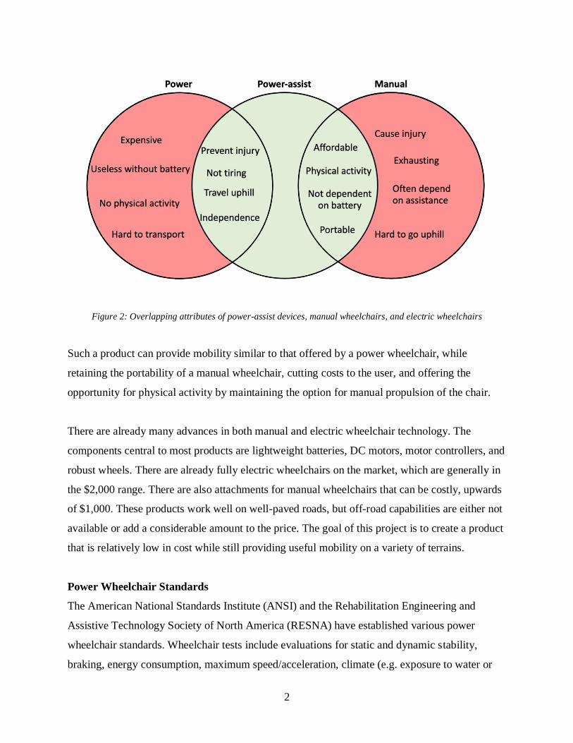
is close to manual wheelchairs in terms of portability versus cost. As shown in Figure 2, a
power-assist device has the potential to combine the best features of both power and manual
wheelchairs.
2
Figure 2: Overlapping attributes of power-assist devices, manual wheelchairs, and electric wheelchairs
Such a product can provide mobility similar to that offered by a power wheelchair, while
retaining the portability of a manual wheelchair, cutting costs to the user, and offering the
opportunity for physical activity by maintaining the option for manual propulsion of the chair.
There are already many advances in both manual and electric wheelchair technology. The
components central to most products are lightweight batteries, DC motors, motor controllers, and
robust wheels. There are already fully electric wheelchairs on the market, which are generally in
the $2,000 range. There are also attachments for manual wheelchairs that can be costly, upwards
of $1,000. These products work well on well-paved roads, but off-road capabilities are either not
available or add a considerable amount to the price. The goal of this project is to create a product
that is relatively low in cost while still providing useful mobility on a variety of terrains.
Power Wheelchair Standards
The American National Standards Institute (ANSI) and the Rehabilitation Engineering and
Assistive Technology Society of North America (RESNA) have established various power
wheelchair standards. Wheelchair tests include evaluations for static and dynamic stability,
braking, energy consumption, maximum speed/acceleration, climate (e.g. exposure to water or

3
hot and cold environments), power and control systems, and static, impact, and fatigue stress [1].
Other important factors when evaluating power wheelchairs are turning radius, easily accessible
and removable batteries, and ease of maintenance [2].
Manual Wheelchair Basics
Manual wheelchairs have a straightforward design that has been used for centuries to allow for
movement of the mobility impaired. They can be foldable, heavy duty, light duty, affordable,
rough terrain capable, and somewhat customizable to fit the user’s needs. Rolling resistance,
propulsion efficiency, and ease of turning are some of the main considerations when dealing with
these chairs [3]. A manual wheelchair was therefore the foundation of the design focus with
electric and mechanical components added as an attachment to enhance the chair’s capability at
an affordable price.
Table 1 summarizes features that are important for all wheelchairs. Some features are not
relevant to this project because we modified an existing manual wheelchair. However, it is
important to keep all wheelchair features in mind in order to create a product most suitable to
users’ needs.
Table 1: Key features of manual and electric wheelchairs
Feature Manual/Electric Description
Handrims Manual Large enough to comfortably spin without reaching too
far down or out from the chair
Speed control Electric Must keep a reasonable speed (3-4 MPH), and be easily
controlled with some kind of remote
Rechargeable
power supply Electric Portable, easy to charge via cable or battery pack
Comfortable
seat Both
Good back support, soft cushioning, easy to get in and
out of
Robust wheels Both Able to move over paved and unpaved terrain
Foot rest Both Adjustable for different sizes of feet, foldable
Arm rests Both Adjustable height
Easy steering Both For electric--various features such as joystick or buttons
For manual--controlled using handrims

4
Control Methods
A variety of control interfaces have been developed to aid wheelchair users besides the
traditional joysticks used by many power wheelchairs or the handrims of manual wheelchairs.
Systems using voice recognition, eye-tracking, and electromyographic (EMG) sensors to
interpret user input and control speed or steering have been created and tested in a variety of
applications [4]. Such control methods eliminate the need for hand-control of the system, which
can be especially beneficial for wheelchair users with limited dexterity or upper body strength.
The team decided to focus on meeting the needs of wheelchair users with normal or close to
normal upper body functionality, so these advanced control systems were beyond the scope of
this project and ultimately were not implemented, but they could be reconsidered for future
iterations of the device.
Ergonomic Solutions for Manual Wheelchairs
One major issue with manual wheelchairs is the stress on shoulders caused by the the hand rim
axle being located behind the wheelchair user’s center of mass [5]. The purpose of putting the
hand rims, which are connected to the drive wheels so far back is to prevent backward tipping.
However, this has been causing wheelchair users chronic overuse injury in the shoulders. Figure
3 shows the proper positioning for a wheelchair user to avoid injury.
Figure 3: Proper alignment that wheelchair users need in order to reduce shoulder injury. This image was
reproduced from reference [5] without permission.

5
The Minneapolis VA Health Care System decided to make a proof-of-concept wheelchair that
separates the hand rims from the drive wheel by using a chain drive. The goal of this wheelchair,
shown in Figure 4, was to improve the ergonomic positioning of hand rims, directly couple the
hand rim to the the drive wheel, and have removable hand rims for easy lateral movement [5].
Figure 4: The Minneapolis VA Health Care System created this wheelchair as their final prototype. This image was
reproduced from reference [5] without permission.
The VA determined that the most ergonomic position for the hand rim is at 10 degrees anterior to
the shoulder and a height that results in a 120 degree elbow angle [5]. Thus, the rims need to be
adjustable to fit all users. A bicycle chain was used to connect the hand rim and drive wheels.
Lastly, a quick release system was made to allow for the hand rims to be removed if the user
wants to move in and out of the wheelchair laterally.
Project Objectives
Few wheelchair products on the market address mobility over multiple terrains and cost at the
same time. It would be best to make a wheelchair that is both manual and electric, so the user can
continue to exercise, but also get assistance for long distances and steep inclines. Many people
do not need a fully electric wheelchair but can use the assistance from a hybrid.

6
This project aimed to improve on existing designs in the following ways:
1. Reduce retail cost below $700.
There are current products that are electric attachments costing between $500-$6,400.
The price of the attachment needed to be in the middle of that range to stay competitive
since the goal of this project was to make something affordable for people with low
incomes, and $700 is affordable in comparison to the existing commercial products. In
addition, subsequent iterations of this design and mass manufacturing could further lower
the cost.
2. Increase ability to move over multiple terrains.
Current manual (and most electric) wheelchairs are only meant for smooth surfaces,
which greatly limits the places disabled people can go. The goal for this modified
wheelchair is to provide rugged wheels, so that disabled people are not limited to
wheelchair access routes. This is especially crucial for users in rural areas or developing
countries due to the lack of paved sidewalks.
3. Help the user travel on inclines without extreme effort.
In manual wheelchairs it is extremely difficult and, in many cases, impossible to ascend
steep inclines. The attachment was designed to enable wheelchair users to easily ascend
steeper hills, giving them more mobility.
4. Allow for variable speed.
Many electric wheelchairs have at least two discrete speed options or even continuously
variable speed capability, and the attachment is no different. Many models of basic
electric wheelchairs go between 3-5 mph with all-terrain chairs reaching upwards of 10
mph [6]. However, manual wheelchairs are not designed for speeds this high, and 5 mph
was chosen as the goal for a safe top speed achievable with this device.
7
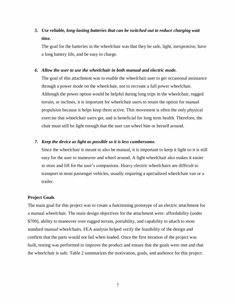
5. Use reliable, long-lasting batteries that can be switched out to reduce charging wait
time.
The goal for the batteries in the wheelchair was that they be safe, light, inexpensive, have
a long battery life, and be easy to charge.
6. Allow the user to use the wheelchair in both manual and electric mode.
The goal of this attachment was to enable the wheelchair user to get occasional assistance
through a power mode on the wheelchair, not to recreate a full power wheelchair.
Although the power option would be helpful during long trips in the wheelchair, rugged
terrain, or inclines, it is important for wheelchair users to retain the option for manual
propulsion because it helps keep them active. This movement is often the only physical
exercise that wheelchair users get, and is beneficial for long term health. Therefore, the
chair must still be light enough that the user can wheel him or herself around.
7. Keep the device as light as possible so it is less cumbersome.
Since the wheelchair is meant to also be manual, it is important to keep it light so it is still
easy for the user to maneuver and wheel around. A light wheelchair also makes it easier
to store and lift for the user’s companions. Heavy electric wheelchairs are difficult to
transport in most passenger vehicles, usually requiring a specialized wheelchair van or a
trailer.
Project Goals
The main goal for this project was to create a functioning prototype of an electric attachment for
a manual wheelchair. The main design objectives for the attachment were: affordability (under
$700), ability to maneuver over rugged terrain, portability, and capability to attach to most
standard manual wheelchairs. FEA analysis helped verify the feasibility of the design and
confirm that the parts would not fail when loaded. Once the first iteration of the project was
built, testing was performed to improve the product and ensure that the goals were met and that
the wheelchair is safe. Table 2 summarizes the motivation, goals, and audience for this project.

8
Table 2: Mission statement summarizing project goals, intended users, and stakeholders.
Mission Statement: Power-Assist Attachment to Manual Wheelchair
Product Description ● Attachment that provides power to a manual wheelchair
Benefit Proposition ● Increase wheelchair users’ mobility/independence at affordable
cost
Key Project Goals ● Create functioning prototype by May 2019
Primary Markets ● Manual wheelchair users needing but unable to afford power
wheelchairs
Secondary Markets ● Power wheelchair users needing more portable wheelchair option
● Manual wheelchair users wanting to travel farther but still get
exercise
Assumptions ● Attaches to manual wheelchair
● Battery-powered
Stakeholders ● Users
● Engineering team
● Faculty Advisors
● SCU Engineering School and Mechanical Engineering Department
9
2. Customer Needs
Demographic Information
In 2010 there were 3.6 million people using wheelchairs in the U.S. [7]. It is estimated that this
number grows by 2 million people each year [8]. Older populations are most likely to use
wheelchairs because of health complications due to aging; however, there are plenty of younger
people that use either manual or electric wheelchairs. As the baby boomer generation ages and
the human lifespan increases there will most likely be a spike in wheelchair usage, increasing
demand for effective products even further.
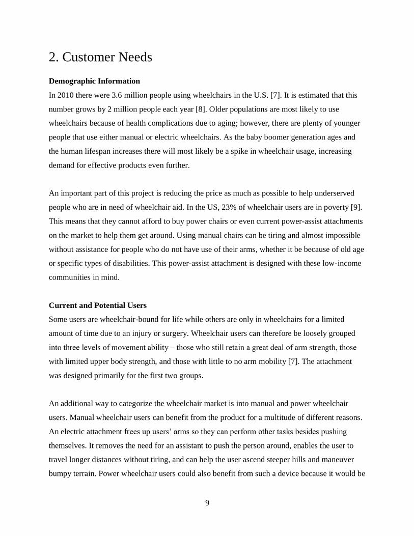
An important part of this project is reducing the price as much as possible to help underserved
people who are in need of wheelchair aid. In the US, 23% of wheelchair users are in poverty [9].
This means that they cannot afford to buy power chairs or even current power-assist attachments
on the market to help them get around. Using manual chairs can be tiring and almost impossible
without assistance for people who do not have use of their arms, whether it be because of old age
or specific types of disabilities. This power-assist attachment is designed with these low-income
communities in mind.
Current and Potential Users
Some users are wheelchair-bound for life while others are only in wheelchairs for a limited
amount of time due to an injury or surgery. Wheelchair users can therefore be loosely grouped
into three levels of movement ability ‒ those who still retain a great deal of arm strength, those
with limited upper body strength, and those with little to no arm mobility [7]. The attachment
was designed primarily for the first two groups.
An additional way to categorize the wheelchair market is into manual and power wheelchair
users. Manual wheelchair users can benefit from the product for a multitude of different reasons.
An electric attachment frees up users’ arms so they can perform other tasks besides pushing
themselves. It removes the need for an assistant to push the person around, enables the user to
travel longer distances without tiring, and can help the user ascend steeper hills and maneuver
bumpy terrain. Power wheelchair users could also benefit from such a device because it would be
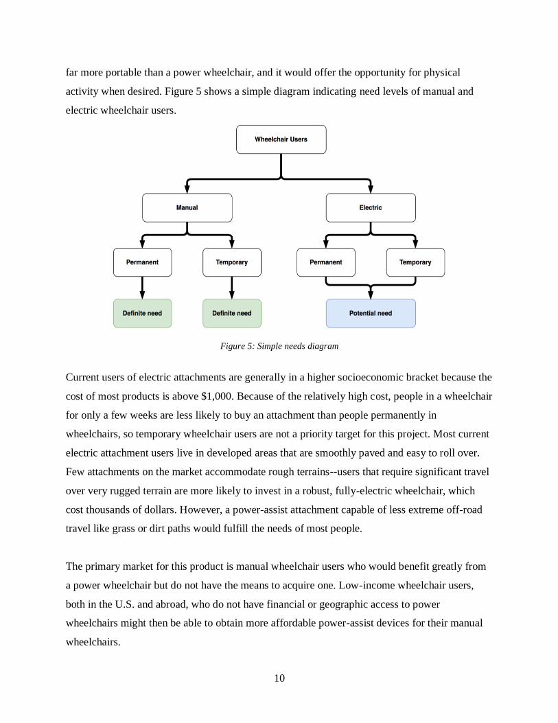
10
far more portable than a power wheelchair, and it would offer the opportunity for physical
activity when desired. Figure 5 shows a simple diagram indicating need levels of manual and
electric wheelchair users.
Figure 5: Simple needs diagram
Current users of electric attachments are generally in a higher socioeconomic bracket because the
cost of most products is above $1,000. Because of the relatively high cost, people in a wheelchair
for only a few weeks are less likely to buy an attachment than people permanently in
wheelchairs, so temporary wheelchair users are not a priority target for this project. Most current
electric attachment users live in developed areas that are smoothly paved and easy to roll over.
Few attachments on the market accommodate rough terrains--users that require significant travel
over very rugged terrain are more likely to invest in a robust, fully-electric wheelchair, which
cost thousands of dollars. However, a power-assist attachment capable of less extreme off-road
travel like grass or dirt paths would fulfill the needs of most people.
The primary market for this product is manual wheelchair users who would benefit greatly from
a power wheelchair but do not have the means to acquire one. Low-income wheelchair users,
both in the U.S. and abroad, who do not have financial or geographic access to power
wheelchairs might then be able to obtain more affordable power-assist devices for their manual
wheelchairs.

11
Customer Needs Research
All products have a targeted customer base, and their needs distinctly define the features of the
products marketed towards them. For the electric assist wheelchair, it was important to gain first-
hand knowledge from the individuals that would be using it. We conducted research in three
ways: phone interviews with two surgeons with experience caring for people in wheelchairs both
in the U.S. and abroad, an in-person interview with a wheelchair saleswoman, and online surveys
of people with disabilities on public forums such as Reddit and Facebook. (Questions asked in
each interview and survey are included in Appendix A)
Surgeon Interviews Summary
The first person interviewed was Dr. Niles Batdorf, a surgeon who works with a hospital in
Nepal. The team learned that most people there rely on wheelchair donations because new chairs
are too expensive to purchase. Usually the donated chairs are manual rather than electric, but the
surgeon said that electric wheelchairs can be a “game-changer” for people with disabilities.
Using manual chairs can be challenging on unpaved terrain, a common feature in rural areas such
as Nepal. A goal for this attachment was to help people travel over dirt paths and other rough
terrain because people in the U.S. might want to be able to travel on unpaved roads as well. With
this feature, therefore, the attachment could increase usability of the wheelchair in both
developed and developing countries.
Another surgeon, Dr. Steve Sparks, has significant experience in San Diego and Cameroon.
During the interview, he emphasized that any device created specifically for the developing
world would need to take into consideration the availability of spare parts, which can be harder
to access in less developed countries. He suggested using as many bike parts as possible because
they are readily available throughout the world. Thicker tires such as mountain bike tires might
be needed to get through mud, sand, or clay. Dr. Sparks also said that if a person was using a
wheelchair in a smaller village then the battery life of a power-assist device would not
necessarily have to be especially long because the individual would not have to travel long
distances. Other potential design considerations would be the impact on the wheelchair’s
stability by adding an additional wheel to the front or back and the possibility of needing to fit
through narrow doorways.

12
Both surgeons thought that charging a battery-powered device in the developing world would not
be too difficult because people find creative ways to get power, especially with the recent influx
of mobile phones. Even though the focus for this project is to cater to wheelchair users in the
United States, the suggestions from the surgeons in developing countries still provided
invaluable input that was applied to the design process for American consumers.
Wheelchair Saleswoman Interview Summary
A saleswoman at Bischoff’s Medical and Mobility in Santa Clara, California, provided
significant insight into the needs of the customers who come in and look for wheelchairs. She
answered the questions provided in Appendix A. She confirmed that the majority of customers
purchase electric wheelchairs over manual ones. The reasoning behind the electric wheelchair
purchases is the convenience of more independence and mobility. Many of the people who go to
Bischoff’s for a manual wheelchair are temporary users and thus want an inexpensive solution;
thus, the most popular manual wheelchairs are the basic, standard 18-inch wheelchairs.
The saleswoman talked about the order of importance for certain features in a wheelchair:
1. Lightweight
2. Comfort
3. Maneuverability over rugged terrain
A lightweight wheelchair weighs 50 pounds or less. The LiteRider Envy by Golden, which is the
most popular wheelchair sold at Bischoff’s, is the favorite because it can be broken into 4
components with the heaviest component weighing only 35 pounds. People want to be able to
easily pick up and put their wheelchair in their car. Thus, the lightweight and easily detachable
and attachable components make this product a best-seller.
The ergonomics of the chair are also important for wheelchair users because users spend so
much time in their chair. Since the attachment is being attached to existing wheelchairs, this
factor was not as important for this project because the existing wheelchair should take this into
account.
13
Finally, the saleswoman talked about the many users who want to be able to go on hiking trails
and other off-road paths with their wheelchair. Almost all users tell her that at minimum they
need to be able to go over grass, which not all wheelchairs can do comfortably. She also has
clients who want wheelchairs that can maneuver on cobblestone and at this point the only
product she sells for this is the scooter, but scooters are not lightweight or portable and tend to be
very expensive.
Reddit/Facebook Survey Summary
The online survey was made available to about 30,000-40,000 wheelchair-using individuals
through Reddit and two Facebook groups. The survey was posted along with a brief summary of
the goals of the project as well as an explanation of how the survey would be used to assist us.
The survey included questions about how the users’ lives are affected by manual and electric
wheelchairs. Also, they were asked about what features they would like to see, as well as the
kind of terrain and distance for which they would like to use an electric assist wheelchair. 18
responses were received.
Summary of Survey Results
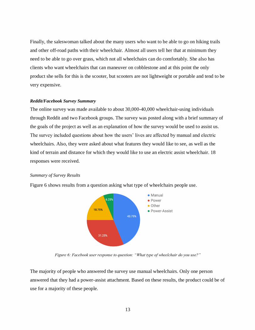
Figure 6 shows results from a question asking what type of wheelchairs people use.
Figure 6: Facebook user response to question: “What type of wheelchair do you use?”
The majority of people who answered the survey use manual wheelchairs. Only one person
answered that they had a power-assist attachment. Based on these results, the product could be of
use for a majority of these people.
14
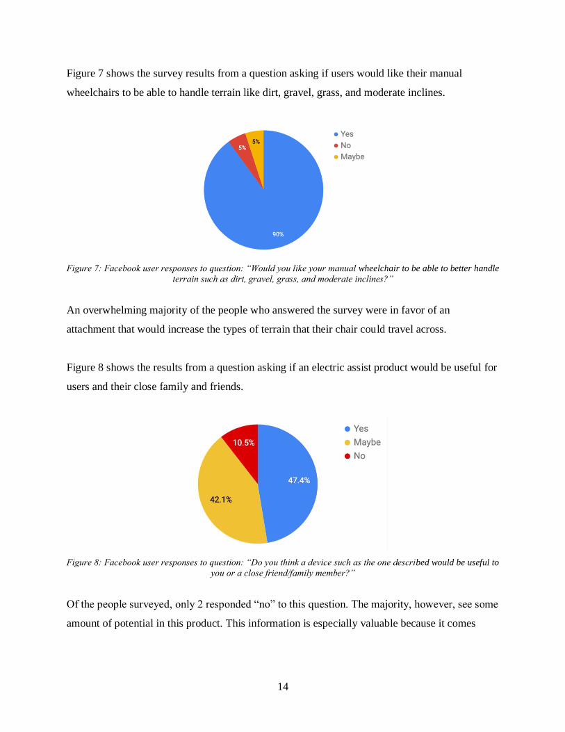
Figure 7 shows the survey results from a question asking if users would like their manual
wheelchairs to be able to handle terrain like dirt, gravel, grass, and moderate inclines.
Figure 7: Facebook user responses to question: “Would you like your manual wheelchair to be able to better handle
terrain such as dirt, gravel, grass, and moderate inclines?”
An overwhelming majority of the people who answered the survey were in favor of an
attachment that would increase the types of terrain that their chair could travel across.
Figure 8 shows the results from a question asking if an electric assist product would be useful for
users and their close family and friends.
Figure 8: Facebook user responses to question: “Do you think a device such as the one described would be useful to
you or a close friend/family member?”
Of the people surveyed, only 2 responded “no” to this question. The majority, however, see some
amount of potential in this product. This information is especially valuable because it comes

15
directly from people who would be using this product. This demonstrates that the project has a
real market and would be able to reach people that need help.
When prompted for their thoughts on speed control for the electric assist attachment, respondents
gave a multitude of ideas. The most popular response was a throttle lever, similar to a thumb
control on an all-terrain vehicle. Other responses included joysticks, pedals, push buttons and
gyroscopic control (similar to a “hoverboard” or Segway). It seems that no single throttle
solution works for all users, since some complained of difficulty and pain when operating
joysticks for extended periods, and others expressed issues with having their hands do the
controlling at all. Although only one control method was chosen for this project, future iterations
could potentially offer users the option to choose among several interfaces for their personal
device.
Needs Hierarchy and Importance
Based on the interviews and surveys performed, a list of customer needs was generated and
organized into similarly themed categories. These categories include a long battery life, the
ability for off-road travel, ease of operation, ease of transportation, possibility for manual
propulsion, ergonomics, weight, and affordability. The importance of each need category was
ranked on a scale from 1 to 5, with 1 being the lowest priority and 5 being the highest. Table 3
summarizes the needs as described by the stakeholders (a more detailed list is in Appendix B).

16
Table 3: List of customer needs ranked by their relative importance
# Need: The device... Mentioned by Rank
1 is affordable. Dr. Batdorf, Saleswoman, Facebook
users
5 2 enables off-road travel. Dr. Sparks, Saleswoman, Facebook users
3 can be easily transported. Saleswoman, Facebook users
4 is durable/reliable. Dr. Sparks, Facebook users
4 5 is easy to operate. Facebook users
6 is lightweight. Saleswoman, Facebook users
7 has a long battery life. Facebook users
3
8 is easy to attach/detach. Saleswoman, Facebook users
9 increases the user’s mobility. Dr. Batdorf, Facebook users
10 is compact. Facebook users
11 is ergonomic. Saleswoman, Facebook users
2 12 does not restrict the user’s
movement. Facebook users
13 allows manual propulsion when
desired. Facebook users
14 functions in inclement weather. Facebook users
1
15 has a simple but useful user interface. Facebook users

17
Through the assessment of the needs from the interviewees and survey respondents, it was
determined that the top needs for the wheelchair attachment are:
1. Affordability: The team addressed this need by maintaining a simple design and using
components that are inexpensive, but safe. Using basic materials helped keep costs down
and maintain the focus on creating the most innovative features.
2. Mobility over unpaved surfaces: To remedy this need, large tires meant for rugged
terrain were used. A couple options considered were mountain bike tires or a third heavy-
duty drive wheel that attaches in the back for trails, grass, and unpaved roads.
3. Portability: It was critical that the electric attachment not add a lot of weight and be
easily detachable to maintain the portability of a manual wheelchair.

18
3. Benchmarking and Product Specifications
Existing wheelchair products can be divided into three basic categories—manual, power, and
power-assist chairs. Each category has unique features that are beneficial in some regard. Manual
wheelchairs and electric wheelchairs were analyzed to understand the important features of each
and the general geometry that this product must be compatible with. Four different wheelchair
attachments were analyzed as well to compare directly to this product. This project seeks to
combine the best parts of each type of wheelchair to create a useful, marketable product.
Manual Wheelchairs
Manual wheelchairs are the cheapest option for wheelchair users. They require the user to be
able to propel themselves forward by turning the wheels via handrims or by having an assistant
push the chair from behind. These chairs are desirable because they allow the user to exercise,
they are lightweight, and they are easy to maneuver [10]. Figure 9 shows a manual wheelchair
that is currently on the market.
Name: Drive Medical Silver Sport 1
Price: $123
Supplier: Overstock
Figure 9: Drive Medical Silver Sport 1. This image was reproduced from reference [11] without permission.
Power Wheelchairs
Power wheelchairs require no energy from the user to operate. They are outfitted with motors
and batteries that are rechargeable and have differing levels of power. Power chairs are preferred
for users who do not have the use of their arms or for users who do not have enough strength to
push themselves [10]. These chairs are more powerful than manual wheelchairs, but they are also
louder, bulkier, and more expensive. Speed, acceleration, and braking mechanisms are important
features to consider with power wheelchairs [3]. Figures 10-12 show different power chair
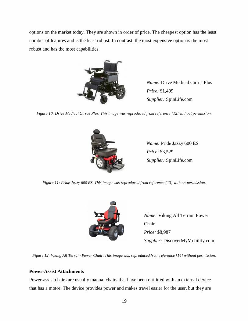
19
options on the market today. They are shown in order of price. The cheapest option has the least
number of features and is the least robust. In contrast, the most expensive option is the most
robust and has the most capabilities.
Name: Drive Medical Cirrus Plus
Price: $1,499
Supplier: SpinLife.com
Figure 10: Drive Medical Cirrus Plus. This image was reproduced from reference [12] without permission.
Name: Pride Jazzy 600 ES
Price: $3,529
Supplier: SpinLife.com
Figure 11: Pride Jazzy 600 ES. This image was reproduced from reference [13] without permission.
Name: Viking All Terrain Power
Chair
Price: $8,987
Supplier: DiscoverMyMobility.com
Figure 12: Viking All Terrain Power Chair. This image was reproduced from reference [14] without permission.
Power-Assist Attachments
Power-assist chairs are usually manual chairs that have been outfitted with an external device
that has a motor. The device provides power and makes travel easier for the user, but they are

20
still able to use their arms and keep their body moving. These attachments are cheaper than fully
powered chairs and are not permanent, so users could take them off and have a manual chair if
they desired. Power assist chairs give the user the ability to use a chair with a slimmer frame
compared to fully powered chairs [10].
Figures 13-15 show different models of power assist attachments. The first attachment has only
one wheel and is designed to attach to the front of the chair and convert it into a scooter-like
vehicle. The second comprises two wheels that replace the original wheelchair wheels. The new
wheel has a hub motor and power-assist controls inside of it. The final attachment is a single
wheel that attaches to the back of the chair. It is capable of moving forwards and backwards as
well as side-to-side.
Name: Firefly
Price: $2395
Supplier: Rio Mobility
Figure 13: Firefly scooter attachment. This image was reproduced from reference [15] without permission.
The Firefly by Rio Mobility turns a manual wheelchair into a fully electric “tricycle.” As shown
in Figure 13, the device attaches to the front of a wheelchair, lifting the front two castors off the
ground and using a larger third wheel with a battery and motor. The throttle and handlebars
enable easy control of the wheelchair as long as the user has a basic level of dexterity, and the
design is able to travel off-road. Although it costs less than many fully-electric wheelchairs, at
nearly $2,400 the Firefly is still very expensive. It is also somewhat difficult to assemble and
does not do well with hills, bumps, or water [16].

21
Name: eMotion M15
Price: $6395
Supplier: Alber/Frank Mobility
Figure 14: eMotion M15 hub motor. This image was reproduced from reference [17] without permission.
Another design, such as the eMotion M15 in Figure 14, replaces the larger two wheels of a
manual wheelchair with wheels that have hub motors. Although the eMotion cannot provide as
much speed or range as the Firefly, the fact that it supplements the user’s effort instead of
completely replacing it enables the person to still get exercise but avoid overexertion [18].
Because it replaces existing parts instead of adding an attachment to the wheelchair, the eMotion
has a much smaller footprint, which is very helpful for navigating tight spaces.
Name: SmartDrive
Price: $6000
Supplier: MAX Mobility
Figure 15: SmartDrive power assist attachment. This image was reproduced from reference [19] without
permission.
A third electric attachment design consists of an extra wheel and motor that are added to the back
of the wheelchair like the SmartDrive MX2 in Figure 15. The Veterans Affairs Assistive
Technology Website gives the SmartDrive MX2 a very favorable review. Similar to the eMotion,
the SmartDrive is a power assist device that seeks to prevent users’ injury or strain while still
allowing them to get physical activity. The SmartDrive is nowhere near as fast as the Firefly, nor
can it handle rugged terrain as well, but at 13.5 pounds it is extremely light and easy to transport,
22
even as a carry-on in an airplane. It is also remarkably easy to attach and detach; however, its
$6000 price tag is too much for many people to afford [20].
Target Specifications
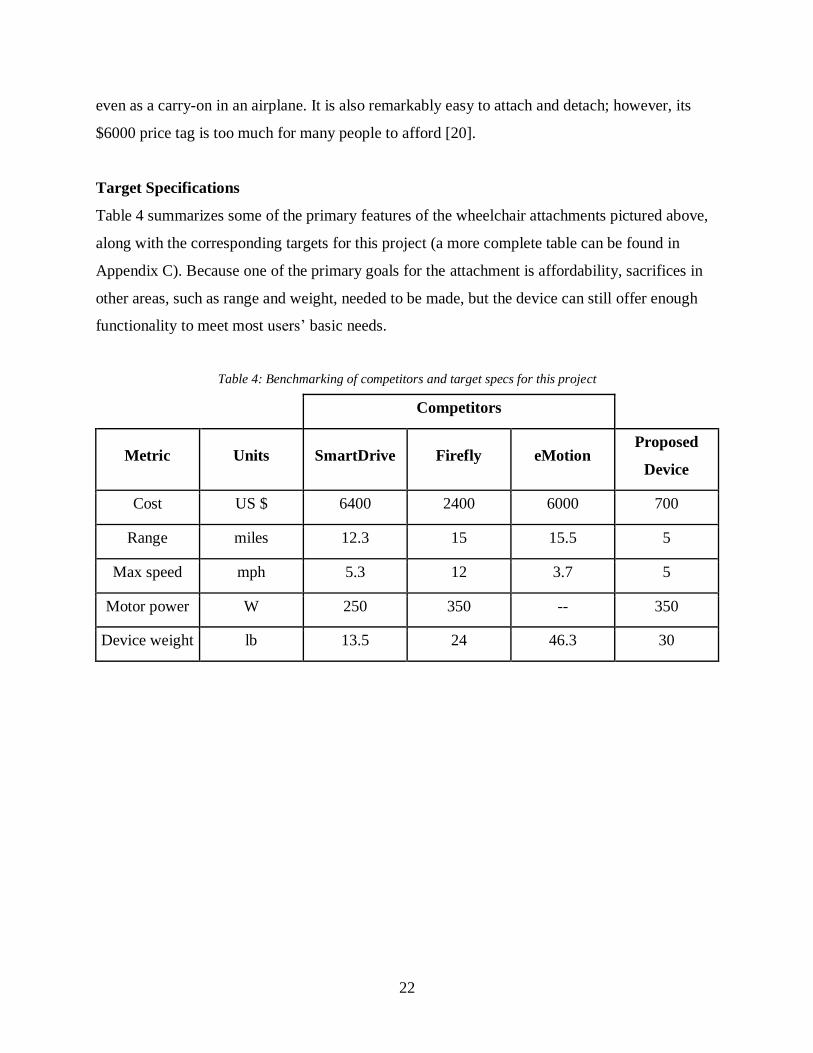
Table 4 summarizes some of the primary features of the wheelchair attachments pictured above,
along with the corresponding targets for this project (a more complete table can be found in
Appendix C). Because one of the primary goals for the attachment is affordability, sacrifices in
other areas, such as range and weight, needed to be made, but the device can still offer enough
functionality to meet most users’ basic needs.
Table 4: Benchmarking of competitors and target specs for this project
Competitors
Metric Units SmartDrive Firefly eMotion Proposed
Device
Cost US $ 6400 2400 6000 700
Range miles 12.3 15 15.5 5
Max speed mph 5.3 12 3.7 5
Motor power W 250 350 -- 350
Device weight lb 13.5 24 46.3 30
23
4. Potential System-Level Solutions
Functional Decomposition
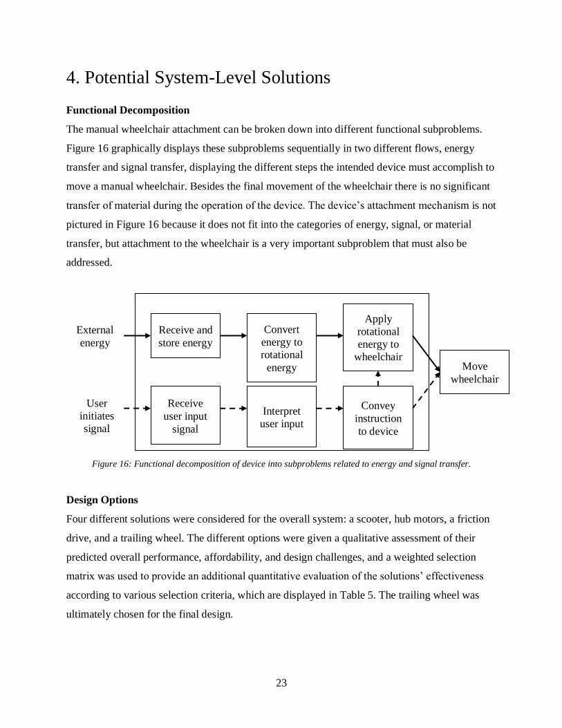
The manual wheelchair attachment can be broken down into different functional subproblems.
Figure 16 graphically displays these subproblems sequentially in two different flows, energy
transfer and signal transfer, displaying the different steps the intended device must accomplish to
move a manual wheelchair. Besides the final movement of the wheelchair there is no significant
transfer of material during the operation of the device. The device’s attachment mechanism is not
pictured in Figure 16 because it does not fit into the categories of energy, signal, or material
transfer, but attachment to the wheelchair is a very important subproblem that must also be
addressed.
Figure 16: Functional decomposition of device into subproblems related to energy and signal transfer.
Design Options
Four different solutions were considered for the overall system: a scooter, hub motors, a friction
drive, and a trailing wheel. The different options were given a qualitative assessment of their
predicted overall performance, affordability, and design challenges, and a weighted selection
matrix was used to provide an additional quantitative evaluation of the solutions’ effectiveness
according to various selection criteria, which are displayed in Table 5. The trailing wheel was
ultimately chosen for the final design.
Receive and
store energy
Convert
energy to
rotational
energy
Apply
rotational
energy to
wheelchair
Receive
user input
signal
Interpret
user input
Convey
instruction
to device
Move
wheelchair
External
energy
User
initiates
signal

24
Scooter
The scooter design, represented by the Firefly in Figure 13, involves adding a front attachment
that converts the wheelchair into a motorized tricycle. A primary benefit of this design is that the
handlebars enable easy steering and speed control, but a device such as this could be harder to
manufacture, involving more welding that could increase the production cost. In addition, the
tricycle orientation has a larger footprint than the other designs, limiting the user’s ability to
navigate more confined spaces such as tight corners on a wheelchair ramp or an elevator.
Hub Motor
Creating wheels with hub motors, such as the eMotion in Figure 14, to replace the user’s
standard wheelchair wheels is another potential solution. Such a design would not increase the
wheelchair’s footprint at all, and because it supplements the propulsion provided by the user
rather than replacing it entirely like the other designs, this solution offers the unique benefit of
physical activity, which is important for wheelchair users’ overall health. However, this can also
be a downside; because they only assist the user’s effort, hub motors might not perform as well
going over bumps like curbs. This design is also harder to attach/detach because the user cannot
be sitting in chair when taking them off or putting them on. The replacement wheels could
simply be left on the wheelchair at all times, but then the wheelchair would weigh too much for
many people to lift it into the trunk of a car, making it difficult to transport. Lastly, this solution
requires a very sophisticated control system that would have been difficult to create within the
limited timeframe for the project and was less suited to the team’s strengths.
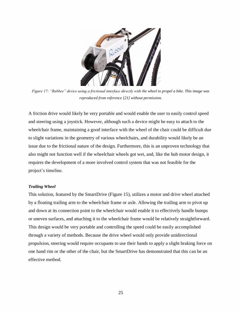
Friction Drive
A recently developed technology used by the Rubbee in Figure 17 to convert a normal bicycle
into an e-bike could be similarly applied to a wheelchair. This solution uses a direct frictional
interface between the device’s drive wheel and the bike wheel to propel the bike, and two similar
units could be created to attach to a wheelchair’s frame and drive its wheels.
25
Figure 17: “Rubbee” device using a frictional interface directly with the wheel to propel a bike. This image was
reproduced from reference [21] without permission.
A friction drive would likely be very portable and would enable the user to easily control speed
and steering using a joystick. However, although such a device might be easy to attach to the
wheelchair frame, maintaining a good interface with the wheel of the chair could be difficult due
to slight variations in the geometry of various wheelchairs, and durability would likely be an
issue due to the frictional nature of the design. Furthermore, this is an unproven technology that
also might not function well if the wheelchair wheels got wet, and, like the hub motor design, it
requires the development of a more involved control system that was not feasible for the
project’s timeline.
Trailing Wheel
This solution, featured by the SmartDrive (Figure 15), utilizes a motor and drive wheel attached
by a floating trailing arm to the wheelchair frame or axle. Allowing the trailing arm to pivot up
and down at its connection point to the wheelchair would enable it to effectively handle bumps
or uneven surfaces, and attaching it to the wheelchair frame would be relatively straightforward.
This design would be very portable and controlling the speed could be easily accomplished
through a variety of methods. Because the drive wheel would only provide unidirectional
propulsion, steering would require occupants to use their hands to apply a slight braking force on
one hand rim or the other of the chair, but the SmartDrive has demonstrated that this can be an
effective method.

26
The selection matrix shown in Table 5 was generated to supplement and quantify aspects of the
analysis above, such as steering, speed control, ease of attachment, durability, portability, and
manufacturability. Each solution was assigned an overall score and compared to a standard
power wheelchair as a reference point.
Table 5: Scoring matrix for design options of the full system
System-level solutions
A
Scooter
B
Hub motors
C
Direct torque
D
Trailing wheel
Reference
Electric
Wheelchair
Selection
criteria Weight Rating Score Rating Score Rating Score Rating Score Rating
Score
Ease of steering 10% 4 0.4 2 0.2 3 0.3 3 0.3 4 0.4
Ease of speed
control 10% 3 0.3 3 0.3 3 0.3 4 0.4 3 0.3
Durability 15% 3 0.45 3 0.45 2 0.3 4 0.6 2 0.3
Ease of attach/
detach 20% 2 0.4 1 0.2 3 0.6 5 1 3 0.6
Portability 25% 2 0.5 5 1.25 4 1 5 1.25 1 0.25
Ease of
manufacturing 20% 2 0.4 5 1 3 0.6 3 0.6 2 0.4
Top Score 2.45 3.4 3.1 4.15 2.25
Rank 4 2 3 1 -
Continue? No No No Yes -
The trailing wheel design not only scored the highest in the selection matrix but avoided some of
the pitfalls encountered in the other solutions and was believed to be best suited to the team’s
strengths and the project timeline and budget; the trailing wheel was thus chosen as the final
system-level design.

27
System Level Model with Main Subsystems
Figure 18 shows a preliminary system-level CAD model composed of four subsystems: the drive
unit, attachment mechanism, user interface, and battery. The model consists of a manual
wheelchair fitted with a rod that can attach and detach from the chair behind the seat. The trailing
arm includes a motor and wheel that are connected to the rod. A battery is attached on top of the
trailing arm or in a separate “batpack” slung over the back of the chair and attached to the motor
with wires. Finally, the user interface is located by the armrest.
Figure 18: System level CAD image showing the four subsystems (wheelchair seat, armrests, and right wheel are
removed to better display the subsystems)
The design is meant to be as convenient as possible for the user; the attachable and detachable
rod enables the trailing arm to be easily removed and transported in a car. Because the battery is
a separate removable unit, the user will not have to lift the entire assembly at once but can
instead handle each lightweight component on its own.
User Interface
Drive
Unit Battery
Attachment
Mechanism

28
Following a description of the team and project management, the solutions that were considered
for each subsystem will be described in detail along with the initial prototype and the improved
final design.

29
5. Team and Project Management
Challenges and Constraints
One big design challenge was how to make the pivot rod easily attachable and detachable for the
user. There were a few different attachment points, but it was determined that ergonomics and
centering were critical, and therefore the pivot rod located in the back was chosen.
Another challenge was the safety-related constraints for the battery. The mechanical engineering
department protocol stated that batteries could not be more than 50V. In addition, it was highly
suggested that batteries be purchased, not made. At first, the best option seemed to be a custom-
made battery comprised of 18650 Lithium-ion cells, soldered together and shrink-wrapped to
prevent any short circuiting. However, after discussing the safety challenges further with the
department, the team decided it would be better to buy a pre-made 36V battery from an
experienced vendor. This decision cut down on time and increased the safety level of the project.
The final constraint on this project was the timeline. Senior design is only a yearlong project, so
everything had to be done very quickly, yet thoroughly. Since this is such a short amount of time,
the team was not able to perfect and polish a ready-for-market product. However, the end
product was still a successful prototype, well on its way to being a marketable device. With more
time and more money, this attachment could be sold in stores.
Budget
The team requested and received $2,000 from the School of Engineering to cover materials,
external labor that could not be done in the school’s machine shop, and a small cushion of money
for unexpected mistakes and costs. The largest costs were the wheelchairs, battery, and motor.
Table 6 shows the full list of budgeted expenses at the beginning of the project. Further
discussion of the project cost can be found in the cost analysis section of this report.

30
Table 6: Full layout of expected expenses
Preliminary
Expenses Cost (USD) Vendor Explanation
Manual Wheelchair
(1) 200 Amazon
Chair for CAD drawing and building
prototype
18v Cordless Drill
Batteries (2-4) 250 Amazon
Pre-engineered batteries requiring no
extra engineering
DC motor (2) 50 Ebay Two size motors to test for optimizing
torque and efficiency
Wiring and
Connectors 50 Del City.com
Wire and connectors needed for
running controller and supplying
voltage
Drive wheel/tire (1) 50 Harbor Freight To transmit power to the ground and
provide traction
Hub motor bike
wheels (2) 300 Ebay
Alternative design that integrates outer
wheels with motors
Programmable Motor
controller (1-2) 100
Robotshop.co
m
Necessary to control speed and have
user input
Aluminum Billet (1) 100 Gorilla Metals Motor housing material
Misc Aluminum (10) 150 Gorilla metals Misc small parts material
Drive chain (1) 50 Amazon Drivetrain component
Assorted sprockets
(2) 50 Amazon Drivetrain components
Welding hourly (2) 150 Local Welding
Shop Labor
Incidentals 600 Unforeseen expenses and materials
TOTAL 2000

31
Timeline
The timeline for this project was be divided into fall, winter, and spring quarter. A full Gantt
Chart can be found in Appendix D.
Fall quarter was centered around design and design analysis. Some of the main goals for fall
quarter were research, determining customer needs, safety review, concept generation, final
design in CAD, and FEA analysis on certain components.
Winter quarter was spent building the attachment and ensuring that the project followed all of the
required safety protocols. The build included the trailing arm, the connecting rod, the battery,
motor, and controller. These components were constructed in parallel by different team members
to reduce the amount of build time. In addition to the physical assembly, the control system was
also developed using an Arduino Uno and a potentiometer knob. The subassemblies were mostly
finished by the end of winter quarter, allowing for a quick assembly time in the spring. This left
ample time for testing and improving the design before the conference.
Finally, spring quarter was used to test and iterate on the first design. There was a big design
change in spring quarter, which prompted another build of all the subsystems. After the team
finished building, the team conducted six tests to ensure the speed, capacity, and usability of the
attachment matched the goals for the overall product. Tests were performed by team members as
well as first-time users. After the Senior Design Conference on May 9th, the team devoted most
of their time to finishing the thesis, due June 7th.
Design Process
The first step in the design process was to gather information and research on current
technologies. From this research a few different full-system technologies were discovered. Then,
stakeholders were interviewed to learn what the customer needs are. The customer needs helped
establish the main objectives and features for the attachment: affordability, portability, and
maneuverability on rugged terrain. In order to start designing, the team had to try out a manual
wheelchair without an attachment to understand how it worked.

32
After this testing and research, the team began brainstorming full system design and subsystem
designs. A concept scoring matrix was used to determine which design fit the needs based on the
chosen selection criteria. After the full-system and subsystem designs were chosen, hand
sketches were done by a few teammates. A scoring matrix was used to determine the best option
and then the hand sketch was turned into the final design CAD model. The CAD model was used
to perform FEA analysis.
Additional design iterations were made until a final design for the first iteration was created. The
team then purchased material and hardware then began machining and working on the controls
for the first prototype of the design.
After the first prototype was proven to be unsuccessful, the team came up with a new design.
Through this reiterative process the team was able to come up with a successful design.
Risks and Mitigation
There were a few risks that were of concern during the build segment of this project. Parts might
arrive late, faulty, or might be damaged if fragile. In order to mitigate these risks, parts were
ordered early (during winter break) to ensure their timely arrival and give extra time to re-order
any necessary parts. In addition, the team found several different buying options in case an initial
part did not work. All of the parts worked well except for the wheelchair, which had folding
arms that were not standard. The team had to reorder another more standard wheelchair at the
beginning of Winter quarter, but this did not cause significant delay.
Another risk was the short project timeline. The team was slightly concerned that this attachment
would require more time to complete than the Senior Design plans allowed. To mitigate this, a
detailed Gantt Chart was created to keep each team member on schedule (included in Appendix
D). The chart also included each person’s responsibilities with regards to the build, testing, and
iterations to ensure that everyone was kept accountable.
The largest risk in this project is the safety of the user. Any possible circuit shortages or motor
malfunctions could cause harm to a wheelchair user or the building team. To address these

33
issues, the battery was kept in a fireproof ammunition can during storage, and a similar can was
attached to the product to contain the battery while in use. The wheelchair was also outfitted with
a killswitch that was connected to the system between the motor and the battery. Thus, if a user
needed to stop and the control knob was not working, he or she could still stop motion and roll
safely to a halt. The wiring harness was built with a 15 amp fuse to ensure that none of the
components experience unsafe current levels. In addition, there were safety concerns with the
lithium iron phosphate battery used for this project. The team took a safety course for handling
the battery and also filled out the required safety paperwork to ensure it was safe to use and store
in the machine shop.
Team management
This team did not follow a rigid management structure. There was a different team leader each
quarter responsible for facilitating communication within the team and between the team and the
faculty advisors. In addition, the leader was responsible for creating goals and timelines and
keeping the team on track. Catherine van Blommestein was the fall quarter leader, Ryan Boyce
was the winter quarter leader, and Rosemary Cole and Matthew Marks were the spring quarter
leaders.
All team members were responsible for their tasks by completing them on time and doing quality
work. Communication across all team members was necessary for a cohesive and successful
team. Once the build part of this project started, there was a minimum of two team members
responsible for a component. Ryan and Catherine were in charge of machining and assembling
the attachment and Rosemary and Matthew were in charge of the wiring and control system.
If team members were ever not fully participating, there was a protocol set in place to have a
discussion within the team to help move forward. If the problem were to continue, the advisors
would be notified. Lack of participation was never a problem as each team member dedicated
ample amounts of time into the project. The communication between members was very strong
and allowed the team to effectively build and test the wheelchair attachment.

34
6. System Usage
The final prototype is shown below in Figure 19. The attachment consists of a wheel connected
to a trailing arm that is pinned to the back of a wheelchair. There is a kill switch and speed dial
on the side of the chair by the user’s hands.
Figure 19: Fully functional prototype
If a user were to purchase one of these attachments, the box would include the following items.
● Fully assembled trailing arm with wheel, motor, and motor controller
● Unassembled clamps with bolts
● Pins
● User interface (kill switch and speed dial) in a protective housing
● Velcro strips
The steps to installing the device are as follows.
1. Use velcro strips to position the user interface on the front of the chair and secure the
wiring harness on the arm rests
2. Attach battery sling to the top of the handlebars
3. Insert battery into sling
4. Insert pivot rod into clamps with the motor plate facing up
5. Secure pivot rod with pins
6. Connect wiring harnesses

35
The user would be able to leave the user interface and clamps on their wheelchair semi-
permanently as they do not affect the function of the wheelchair. The attachment would be
removable as necessary.
The procedure to use the fully installed device are relatively simple.
1. Verify kill switch is disengaged
2. Adjust dial to desired speed
3. Use hands to steer while rolling
4. To turn off, set the dial to the “OFF” position and/or hit the kill switch
5. Disconnect battery and sling from harness for easy charging
If this product were to go to market, it would be sold alongside a manual outlining these steps to
ensure the user knows exactly how to operate the device.

36
7. Subsystem 1: Drive Unit
The drive unit consists of the motor and wheel, which are responsible for generating the power
required to propel the wheelchair. The motor needed to provide enough power to propel a 250
pound user at constant speed up to 5 miles per hour. The motor also had to be capable of variable
output, so users could adjust their speed. The ideal motor needed to be lightweight in order to
make the device easily portable; however, minimizing the weight and maximizing the power
output are conflicting objectives. Balancing these goals was one trade-off when selecting a
motor. Another trade-off was between the motor’s power and cost.
The wheel had to be large enough in diameter to be able to travel over small
obstacles/bumps/cracks, and the tire surface had to provide enough traction to enable traveling
over grass or packed dirt. Wider wheels would increase the contact area with the ground and
improve traction; however, this design required the drive wheel to be located slightly behind the
axle of the wheelchair’s large wheels, which causes the wheel to “scrub,” or slide laterally, when
the wheelchair user pivots or turns sharply. Wider wheels would make this movement more
difficult. The wheel selection came second to the motor selection.
Drive Unit Options
The motors considered for this project were all found on eBay. This vendor gave a wide range of
reliable products at fair prices. DC motors are more commonly used for this type of application
than AC motors. Of the three motors being highly considered, two were brushed motors and one
was brushless. Each had a different voltage and power capacity. Ultimately, the team decided to
purchase and use the brushless hub motor.
24V Brushed Motor
The motor shown in Figure 20 is marketed as a Go-Kart product. Go-Karts are similar to
wheelchairs in that they transport people of various weights at constant speeds, so this type of
motor fit well with the purpose of the attachment. It is a 24V motor that can provide 500 watts of
power. It costs $59.90. If this motor were chosen for the final design, it would require a separate
wheel attachment.

37
Figure 20: 24V Go-Kart motor. This image was reproduced from reference [22] without permission.
36V Brushed Motor
The second motor considered was a 36V motor that could be purchased alone or with a motor
controller and throttle. The marketed purpose for this set is for an electric scooter. The motor is
shown in Figure 21. It could provide up to 450 watts of power and cost $96.99. Buying a motor
with a compatible control kit could cut down on shipping time and simplify the design. However,
the wheelchair users interviewed did not like using throttles because they require constant force.
Figure 21: 36V motor. This image was reproduced from reference [23] without permission.
Brushless Hub Motor
The final motor considered for use in this design was a hub motor that was attached to an 8-inch
wheel. The Kun Ray motor (photo and CAD shown in Figure 22) cost $45. It provides 350 Watts
of power and comes in 24V, 36V, and 48V models.

38
Figure 22: Photo (left) and CAD model (right) of Kun Ray brushless hub motor. This image was reproduced from
reference [24] without permission.
First Prototype: Hub Motor
Each of the three motor options would have been adequate for the creation of this attachment.
The brushless motor had the benefit of including a wheel, thus eliminating an extra expense on
top of being the cheapest of the three options. Both of the brushed motors had higher power
capacity than the hub motor, though they came at a high price and required buying an additional
wheel. Having a wheel separate from the motor could have created a challenge in building the
attachment in terms of symmetry and keeping everything exactly in the center of the pivot rod.
The 36V hub motor was selected as the best choice for the attachment because it was
inexpensive and combined the drive unit into one piece rather than two, thus simplifying the
manufacturing required and the overall design.
Preliminary Friction Analysis
A primary concern for the hub motor was the possibility of slipping, which would occur if the
force required to push the wheelchair exceeded the traction (friction) force the drive wheel was
able to supply. The overall rolling resistance coefficient of the wheelchair was determined by
performing a simple test using a force gauge to measure the force required to push the
wheelchair at constant speed when carrying a known load on a flat surface. The worst case
scenario of pushing 250 lbs. (200 lb. occupant plus weight of wheelchair and device) up an 8.3%
grade was then considered, and the force required to push the wheelchair and occupant was
calculated to be approximately 28 pounds.

39
In order to ensure that the wheel did not slip, calculations were made for the drive wheel based
off of a free body diagram. Since the battery could have been placed directly on the trailing arm,
calculations were done for each case. It was assumed that the static friction force was 0.7
between the wheel and asphalt. The weight of the hub motor and the hub motor plus the
battery/battery box were 8.15 lbs and 28.15 lbs respectively. The results were that the pushing
force at which the wheel began to slip was 19.0 lbs for just the hub motor and 65.7 lbs for the
hub motor and the battery/battery box (See Appendix E1 for all Drive Unit calculations).
The force required to push the wheelchair (28 lbs.) is greater than the force at which slipping
occurs (19 lbs.) without the additional weight of the battery, so it was determined that the battery
needed to be placed on the trailing arm to achieve enough traction.
Testing Results
Unfortunately, even with the extra weight provided by the battery, the hub motor did not provide
enough torque to move the wheelchair. The hub motor, likely designed for high-speed, low-
torque applications, (such as an electric scooter), did not have as much torque as initially
expected and could not be used for this low-speed, high-torque wheelchair application. Also,
even if the motor had had enough torque, the tread of the tire was made of relatively slick rubber
that would have been suitable for paved surfaces but not for dirt or grass.
To improve on this first prototype, the team decided to use a readily available brushed motor that
could be mounted onto many different types of wheels. This allowed for more design modularity
in order to quickly produce a functional prototype by the time of the showcase.
Second Prototype: Brushed Gear Reduction Motor
To address the insufficient torque of the first prototype, the team re-evaluated the design and
chose to move forward with the gear reduction motor shown earlier in Figure 21. The motor had
a small 9-tooth sprocket meant to mate with a chain, which was used in combination with a
larger sprocket connected to the wheel to further gear-down the output and produce more torque.
The full assembly of the motor and drivetrain is shown below in Figure 23.

40
Figure 23: Two views showing the motor, small and large sprockets, chain, and wheel
The wheel used for the second prototype was much larger than the hub motor wheel. The wheel
diameter was 12 inches and the width was 4 inches, providing much more surface area to aid
with the friction between the attachment and the ground. In addition, the tread was much larger
than the hub motor tire which also improved traction.
The design change from hub motor to gear reduction motor gave the attachment enough torque
and traction to successfully propel the wheelchair and user forward. This success came with
some trade-offs; the new design increased the weight of the attachment, making it slightly more
cumbersome, and added a chain, which is an extra hazard that required an additional guard.
Despite the additional weight and extra safety protection, the success of the second prototype
justified the design decisions that were made.
41
8. Subsystem 2: Attachment Mechanism
The attachment/suspension subsystem secures the drive unit to the wheelchair and transfers force
from the drive unit to the wheelchair. The attachment system must be very easy to operate, so
that a wheelchair user with normal upper body strength and mobility can attach and detach the
drive unit from the wheelchair. Any members or joints must be durable and stiff enough to keep
the drive unit in place, and the attachment mechanism must not prevent the wheelchair from
folding. The subsystem must also maintain enough downward force between the wheel and the
ground to prevent the wheel from slipping.
Attachment Design Options
There are several possible methods for attaching the drive unit to the wheelchair, including a
folding X-frame, a telescoping rod, and a tubing clamp with a pin lock. The tubing clamp was
selected as the final design.
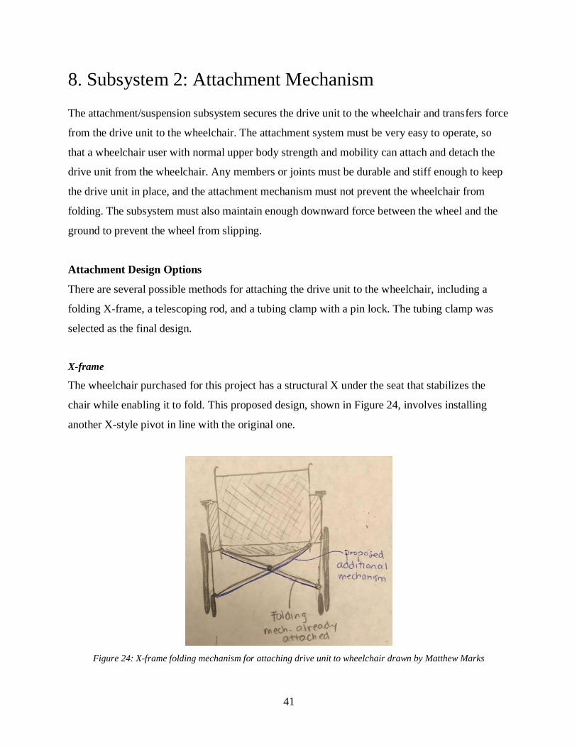
X-frame
The wheelchair purchased for this project has a structural X under the seat that stabilizes the
chair while enabling it to fold. This proposed design, shown in Figure 24, involves installing
another X-style pivot in line with the original one.
Figure 24: X-frame folding mechanism for attaching drive unit to wheelchair drawn by Matthew Marks

42
The motor would attach to the X frame and the chair would be able to fold even while the motor
is still attached.
Telescoping Rod
As shown in Figure 25, another design involves adding a telescoping rod that could be connected
to the back side of the wheelchair’s frame.
Figure 25: Telescoping rod attachment mechanism drawn by Catherine van Blommestein
The trailing arm for the wheel/motor could be attached to the middle part of the rod. The two
sides could be made to collapse into the middle rod, so that the rod could contract when the user
folds the wheelchair inward, which is important for portability.
Clamp with Pin Lock
One more initial design considered for the attachment mechanism is illustrated in Figure 26. A
tubing clamp made of a material with larger diameter than the chair frame would allow simple
and strong mounting onto the frame without permanent modification. The clamp would use
screws or hose clamps for retention and would be removed with simple hand tools.

43
Figure 26: Clamp and pin lock attachment mechanism drawn by Ryan Boyce
This clamp could also feature a threaded boss into which the hitch pin could be attached. The
hitch pin would allow the attachment to pivot about one axis while remaining constrained in all
other other directions. The pin could have a chamfer on one end to speed up installation as well
as a “lynch” style pin to keep the attachment on the pin.
Design Decision: Clamp with Pin Lock
Each design has strengths and weaknesses; the X-frame and telescoping rod maintain the
foldability of the wheelchair, but they would attach to the wheelchair in locations that would be
difficult for the user to reach when attaching or detaching the drive unit. In addition, these
designs would be harder to manufacture. The clamp and pin design would require that part of the
attachment mechanism itself (the rod) would need to be removed in addition to the drive unit
before folding the wheelchair; however, this design would be easier to build and could be placed
in a more convenient location for the user to access. After evaluating each design and ranking
them in a decision/scoring matrix (included in Appendix F), the clamp and pin design was
chosen for further development. Even though it requires removing the rod before folding the
wheelchair, the mechanism would be in an easily accessible location, so this would not be a
significant impediment.

44
Several design iterations were performed, and a CAD rendering of the entire attachment
subsystem is depicted in Figure 27.
Figure 27: Attachment/trailing arm mechanism subsystem modeled by Rosemary Cole
The attachment mechanism consists of two custom-made tube clamps, a pivot rod, and a trailing
arm subassembly that can rotate about the pivot rod. As shown in Figure 27, the clamps fit
tightly around the vertical legs of the wheelchair and are bolted to ensure they do not rotate or
move up and down.
The pivot rod stretches across the back of the wheelchair and slides into the slots in the clamps,
and there is a hole for a pin that secures the rod and prevents it from moving. A mill was used to
machine the clamps, and aluminum was chosen for these parts because it has a high strength-to-
weight ratio.
The trailing arm extends from the pivot rod to connect it to the hub motor. This subassembly has
a pivot rod “sheath” made of tubing that fits around the pivot rod and can rotate about it. The
sheath’s lateral motion is constrained by C-clamps, and two additional pieces of tubing are
welded to the sheath and extend backwards to hold the hub motor. A flat sheet is welded on top
of the tubes for mounting the battery, and two small slotted plates are welded at the end of the

45
tubes to interface with the axle of the wheel. Mild steel was used for the tubing and sheets due to
its strength, affordability, and ease of welding.
FEA Analysis
Finite element analysis (FEA) simulations were performed using SolidWorks to examine two
crucial aspects of the attachment subsystem, the pivot rod and the battery platform. The pivot rod
is a relatively simple part, but it must not bend under the force applied by the hub motor that
pushes the wheelchair.
Figure 28 shows the expected deflection in the pivot rod when subjected to the maximum
expected force of 28 pounds that would occur when the device is pushing a 200 pound person up
an 8% grade.
Figure 28: The deflection simulation shows the maximum deflection will be very minimal.
This FEA simulation showed that the most deflection in the rod with a 28 pound force would be
1.79x10⁻³ inches. These results aligned with the team’s expectations of minimal deflection along
the beam. The material and tube diameter were chosen to maximize strength because this part is
46
so crucial to the integrity of this design. This simulation showed that the materials used to build
the prototype are well suited for their function.
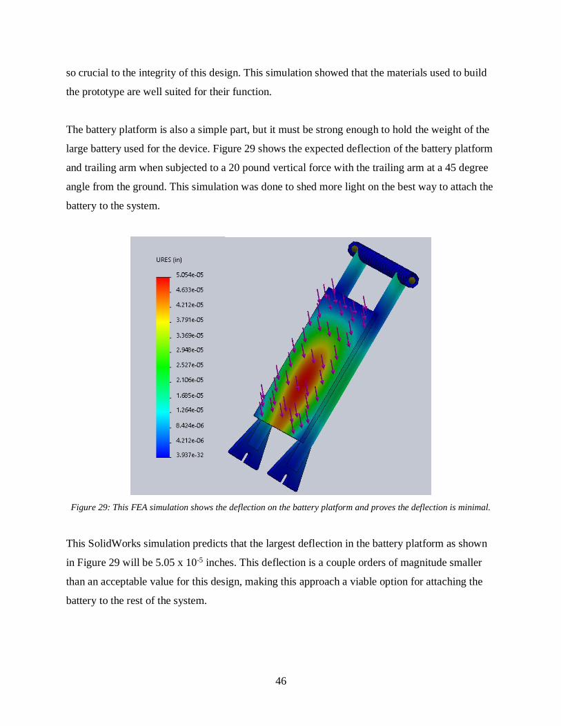
The battery platform is also a simple part, but it must be strong enough to hold the weight of the
large battery used for the device. Figure 29 shows the expected deflection of the battery platform
and trailing arm when subjected to a 20 pound vertical force with the trailing arm at a 45 degree
angle from the ground. This simulation was done to shed more light on the best way to attach the
battery to the system.
Figure 29: This FEA simulation shows the deflection on the battery platform and proves the deflection is minimal.
This SolidWorks simulation predicts that the largest deflection in the battery platform as shown
in Figure 29 will be 5.05 x 10⁻⁵ inches. This deflection is a couple orders of magnitude smaller
than an acceptable value for this design, making this approach a viable option for attaching the
battery to the rest of the system.
47
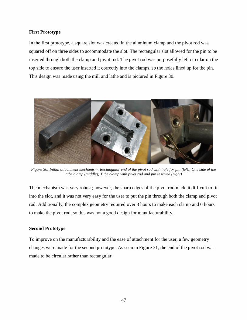
First Prototype
In the first prototype, a square slot was created in the aluminum clamp and the pivot rod was
squared off on three sides to accommodate the slot. The rectangular slot allowed for the pin to be
inserted through both the clamp and pivot rod. The pivot rod was purposefully left circular on the
top side to ensure the user inserted it correctly into the clamps, so the holes lined up for the pin.
This design was made using the mill and lathe and is pictured in Figure 30.
Figure 30: Initial attachment mechanism: Rectangular end of the pivot rod with hole for pin (left); One side of the
tube clamp (middle); Tube clamp with pivot rod and pin inserted (right)
The mechanism was very robust; however, the sharp edges of the pivot rod made it difficult to fit
into the slot, and it was not very easy for the user to put the pin through both the clamp and pivot
rod. Additionally, the complex geometry required over 3 hours to make each clamp and 6 hours
to make the pivot rod, so this was not a good design for manufacturability.
Second Prototype
To improve on the manufacturability and the ease of attachment for the user, a few geometry
changes were made for the second prototype. As seen in Figure 31, the end of the pivot rod was
made to be circular rather than rectangular.
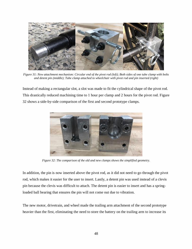
48
Figure 31: New attachment mechanism: Circular end of the pivot rod (left); Both sides of one tube clamp with bolts
and detent pin (middle); Tube clamp attached to wheelchair with pivot rod and pin inserted (right)
Instead of making a rectangular slot, a slot was made to fit the cylindrical shape of the pivot rod.
This drastically reduced machining time to 1 hour per clamp and 2 hours for the pivot rod. Figure
32 shows a side-by-side comparison of the first and second prototype clamps.
Figure 32: The comparison of the old and new clamps shows the simplified geometry.
In addition, the pin is now inserted above the pivot rod, as it did not need to go through the pivot
rod, which makes it easier for the user to insert. Lastly, a detent pin was used instead of a clevis
pin because the clevis was difficult to attach. The detent pin is easier to insert and has a spring-
loaded ball bearing that ensures the pin will not come out due to vibration.
The new motor, drivetrain, and wheel made the trailing arm attachment of the second prototype
heavier than the first, eliminating the need to store the battery on the trailing arm to increase its

49
weight and achieve enough traction. Therefore, a new attachment was made for the battery in the
form of a battery sling, as seen in Figure 33.
Figure 33: The battery sling held by the handlebars stores the battery.
The battery sling was made of duck canvas and Velcro was used to secure the sling around the
handlebars of the wheelchair. Storing the battery in a separate location helped prevent the trailing
arm from becoming unnecessarily heavy.

50
9. Subsystem 3: User Interface
The user interface enables the wheelchair user to control the device. It is not directly attached to
the drive unit but is instead located on the arms of the wheelchair so that the user can easily
access it. In designing this subsystem, multiple requirements were considered:
1. The interface must be intuitive.
2. The interface must be able to maintain speed without requiring the user to constantly
have a hand on it.
3. The interface must be connected to an emergency stop button.
Interface Design Options
Three different user interface designs were analyzed using the criteria listed above. The first was
a joystick similar to what is found on many electric wheelchairs, the second a throttle, and the
third a knob. The knob was selected for the final design.
Joystick
Figure 34 shows an example of the joystick design that could be useful for this product. This
device would work well since it is the industry standard for electric wheelchairs and is easy to
integrate with existing motor controllers. The downside is that it requires one of the user’s hands
for operation at all times, which may be difficult if the operator wants to steer, typically done
with two hands. However, it is intuitive and could be connected to an emergency stop without
too much trouble. The joystick design fulfills two of the three required criteria.
Figure 34: Joystick. This image was reproduced from reference [25] without permission.

51
Throttle
Another potential means for speed control is a throttle. Customer needs research revealed that a
joystick can cause significant hand/wrist soreness because the user must constantly hold it in
place. One way to circumvent this disadvantage is to use a “boat-style” throttle, such as that in
Figure 35, that would stay in place rather than springing back to a neutral position once released.
This would also enable the user to set a speed and then let go of the throttle, thus freeing both
hands to be used for steering, similar to the SmartDrive. This design would require a very easily
accessible kill-switch so that the user could stop the motor quickly. With the addition of a kill
switch, the throttle fulfills all three of the required criteria.
Figure 35: Boat throttle. This image was reproduced from reference [26] without permission.
Knob and Button
The final design considered uses a potentiometer knob like the one in Figure 36, similar to a
volume button that is used to control a car radio. The dial part can be rotated to engage the motor
and propel the user to the set speed. When the user wishes to stop or disengage the electric assist,
the knob can be switched to the off position. A button can be positioned on both sides of the
wheelchair at the end of the armrest for easy accessibility by both hands. A kill switch is easy to
configure to this system as well. This design easily fulfills all three of the required criteria.

52
Figure 36: Potentiometer with a knob. This image was reproduced from reference [27] without permission.
Design Decision: Potentiometer Knob
Through careful considerations of all user interface options, it was decided that the potentiometer
knob combination was the best design for this product. Using this technology over the other
options did not have many trade-offs; neither the joystick or throttle offer anything better for this
purpose. It is a familiar technology that most users will be able to understand without instruction
and the emergency stop feature fits seamlessly into the design. It is more ergonomic than a
joystick and more compact than a throttle. Additionally, units like these can be found pre-made
and ready to be programmed for any application. As shown in the selection matrices found in
Appendix F, the knob option scored 4.8 out of 5, which was over one point higher than the other
two designs based on ergonomics, cruise control ability, durability, and ease of manufacturing.
Figure 37 shows an initial CAD model of the potentiometer and a kill-switch for safety.
Figure 37: Initial CAD model of potentiometer knob and kill-switch for user interface

53
First Prototype
The hub motor selected for the design is a 350W motor, and the battery is 36V, so the maximum
current between them is approximately 10A. A motor controller produced by DROK, shown in
Figure 38, that can operate between 6-50V, up to 380W, and up to 20A, was chosen. The
controller has built-in protection against excessive current and shuts down and produces no
output current if the input current is too high.
Figure 38: Motor controller made by DROK with potentiometer knob for speed control. This image was reproduced
from reference [28] without permission.
The motor controller included a potentiometer knob for controlling speed, which was improved
by adding a larger dial to make it easier to use; however, rather than connecting the dial directly
to the motor controller, it was connected as an input to an Arduino UNO microcontroller, shown
in Figure 39.
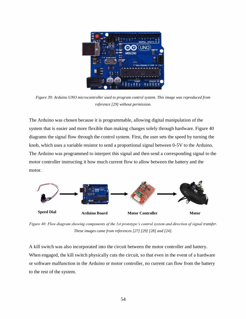
54
Figure 39: Arduino UNO microcontroller used to program control system. This image was reproduced from
reference [29] without permission.
The Arduino was chosen because it is programmable, allowing digital manipulation of the
system that is easier and more flexible than making changes solely through hardware. Figure 40
diagrams the signal flow through the control system. First, the user sets the speed by turning the
knob, which uses a variable resistor to send a proportional signal between 0-5V to the Arduino.
The Arduino was programmed to interpret this signal and then send a corresponding signal to the
motor controller instructing it how much current flow to allow between the battery and the
motor.
Figure 40: Flow diagram showing components of the 1st prototype’s control system and direction of signal transfer.
These images came from references [27] [29] [28] and [24].
A kill switch was also incorporated into the circuit between the motor controller and battery.
When engaged, the kill switch physically cuts the circuit, so that even in the event of a hardware
or software malfunction in the Arduino or motor controller, no current can flow from the battery
to the rest of the system.
Speed Dial Arduino Board Motor Controller Motor

55
Although this user interface and control system worked well, it had numerous inconvenient pin
connections that needed to be soldered. Furthermore, the Arduino and motor controller had to be
stored under the battery plate on the trailing arm, but the box housing these electronic
components was 3D-printed and thus susceptible to damage if a rock or other object was kicked
up by the wheel.
Second Prototype
The second prototype relieved the need for an Arduino. A new motor controller, shown in Figure
41, was chosen for its compatibility with the new motor and came from the same supplier.
Figure 41: The new motor controller. This image was reproduced from reference [30] without permission.
The potentiometer was connected directly to the motor controller, so small pin connections no
longer had to be soldered on any circuit boards. This cut down manufacturing time and removed
an unnecessary component, simplifying the overall signal flow, pictured in Figure 42.
Figure 42: Flow diagram showing components of the 2nd prototype’s control system and direction of signal
transfer. These images came from references [27] [30] and [23].
Speed dial Motor Controller Motor

56
Moreover, the motor controller came in an aluminum enclosure, which provided much better
protection for the controller than the previous plastic, 3D-printed box. Because the battery was
no longer stored on the trailing arm for the second prototype, space became available on top of
the motor mount plate to affix the motor controller, which offered further protection for the
motor controller.
The kill switch was incorporated into the control system for the second prototype, and a 3D-
printed box, displayed in Figure 43, was created to house the potentiometer and kill switch.
Figure 43: 3D-printed housing for potentiometer and kill-switch attached to the side of the wheelchair near the
armrest
The box was attached near the armrest of the wheelchair such that the speed dial and kill-switch
would be very close to where users would naturally rest their hands.

57
10. Subsystem 4: Battery
Rechargeable batteries have been used in commercial products for nearly a century, ranging from
tiny medical devices to powerful electric trucks. Many different types of batteries are available,
with a wide range of efficiency, power density, durability and safety considerations.
Battery Options
Table 7 shows a brief synopsis of a few important characteristics of some common battery types.
All of these batteries were considered as the power source for the power-assist attachment.
Table 7: Comparison of different battery types [31] [32] [33]
Battery Type Specific Power
(Watts/Kg)
Cost
($/Watt-hour)
Cycle Durability
(# of recharge
cycles)
Lead Acid 150-180 0.06-0.15 500
Alkaline 50 2.08 100
Nickel Iron 100 0.19-0.24 5000
Nickel Metal Hydride 250-1000 0.30 300-800
Lithium Iron
Phosphate
200 0.20-0.33 7000
Lithium Cobalt Oxide 50-100 0.36 300-700
Design Decision: Lithium Iron Phosphate
Of the available batteries, lead acid was the least expensive at as low as 6 cents per Watt-hour,
but it does not provide as much power per weight as other varieties such as nickel metal hydride
or lithium ion phosphate. These batteries cost more per energy, but the weight saved by using a
battery with higher energy density justifies the extra expense because the device needed to be
lightweight and easily portable. The team decided to use a lithium iron phosphate battery (shown
in Figure 44) over an lithium ion battery.
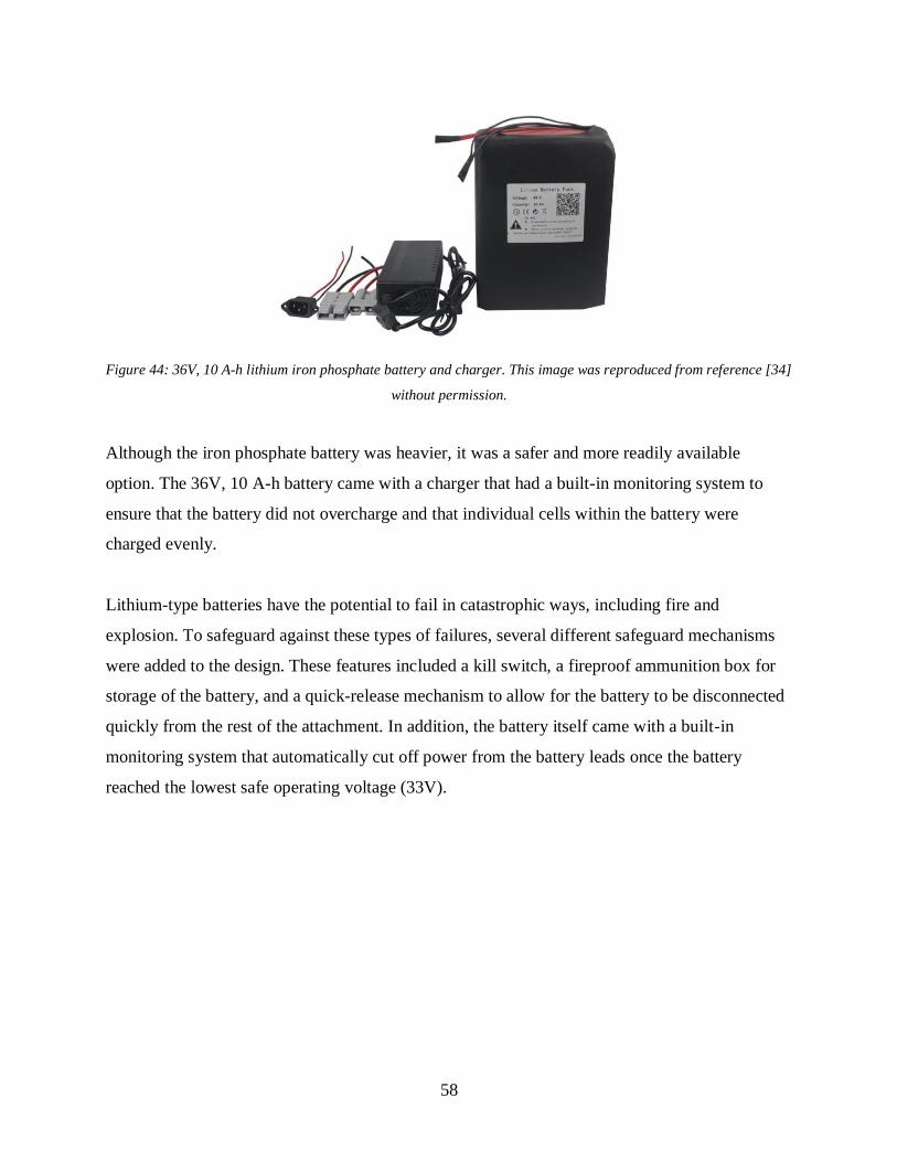
58
Figure 44: 36V, 10 A-h lithium iron phosphate battery and charger. This image was reproduced from reference [34]
without permission.
Although the iron phosphate battery was heavier, it was a safer and more readily available
option. The 36V, 10 A-h battery came with a charger that had a built-in monitoring system to
ensure that the battery did not overcharge and that individual cells within the battery were
charged evenly.
Lithium-type batteries have the potential to fail in catastrophic ways, including fire and
explosion. To safeguard against these types of failures, several different safeguard mechanisms
were added to the design. These features included a kill switch, a fireproof ammunition box for
storage of the battery, and a quick-release mechanism to allow for the battery to be disconnected
quickly from the rest of the attachment. In addition, the battery itself came with a built-in
monitoring system that automatically cut off power from the battery leads once the battery
reached the lowest safe operating voltage (33V).

59
11. System Testing
Once all four subsystems were created and assembled, the entire system was tested to measure
the following specifications: terrain and incline capability, maximum speed on asphalt and turf,
range, time required to attach the device to the wheelchair, and weight. Significant results are
included below, and raw data from testing can be found in Appendix H.
Terrain and Incline
Off-road capability was an important goal for the device, so it was tested on a variety of surfaces,
and, as recorded in Table 8, its performance was qualitatively rated as “incapable,” “poor,”
“satisfactory,” or “very good.”
Table 8: Performance on various terrain rated as either: Incapable, Poor, Satisfactory, or Very Good.
Surface Performance
Asphalt/Concrete Very Good
Cobblestone Very Good
Grass Very Good
Artificial turf Very Good
Hard-packed dirt Very Good
Gravel Satisfactory
8% Incline Very Good
23% Incline Very Good
Speed Bump Very Good
The attachment was able to propel the wheelchair with “Very Good” performance over every
surface tested except for gravel, over which the drive wheel experienced occasional slipping but
was overall “Satisfactory.” This project only sought to design for traveling up a grade of 8%,
which is a standard maximum incline for wheelchair ramps, but the device had no difficulty
propelling the wheelchair and occupant up a 23% incline (the steepest slope that could be found

60
for testing). The terrain and incline testing showed that changes made to the design of the second
prototype succeeded in addressing the insufficient torque and traction of the first prototype.
Maximum Speed
The maximum speed of the wheelchair when propelled by the device was determined by
measuring the time required to travel 17.5 ft. on a flat surface. Starting and ending points were
marked, and the operator started the wheelchair far enough behind the initial mark to provide
sufficient time to accelerate to maximum speed. This test was repeated three times on two
different surfaces, asphalt and artificial turf, and the averaged results are shown in Table 9 with
the target design specifications and the marginally acceptable values.
Table 9: Average maximum speed on asphalt and turf compared to target and min/max acceptable values.
Surface Min
(mph)
Target
(mph)
Max
(mph)
Measured
(mph)
Asphalt 4.5 5 5.5 3.5
Artificial Turf 3 4 5.5 3.3
The device did not meet the target specifications for speed on either asphalt or turf, although the
speed on turf was within the acceptable range. Due to the limited time available for redesigning
and fabricating the second prototype, we had to use sprockets that were readily accessible even
though they did not provide the ideal gear ratio to achieve the target speed. However, after
testing the device we found that 3.5 mph was a sufficient top speed, and that going any faster
would likely be disconcerting or even unsafe for the occupant. Thus, although the design
specifications were not met, the final performance was considered satisfactory.
Range
The range was tested by completely charging the battery and then operating the device
continuously until the battery’s built-in monitoring system cut power once the lowest acceptable
voltage of 33V was reached. A field of artificial turf was chosen for the range test because it
provided sufficient open space for an extended test. Battery voltage readings were taken

61
approximately every 5 minutes throughout the test (shorter intervals at the beginning and end of
the test) in order to generate a battery discharge graph, which can be seen in Figure 45.
Figure 45: Battery voltage during range test on artificial turf, starting at 40.6V and ending at 33V after 161 minutes
The battery voltage began at 40.6V and ended at 33V after 161 minutes, and the voltage drop
was similar to the discharge behavior of typical lithium iron phosphate batteries, which
experience a very slow linear decrease for the majority of discharge except for a rapid drop-off at
the very beginning and end. Given a measured speed of 3.3 mph on artificial turf, the time
traveled (161 minutes) was used to calculate an approximate range of 8.9 miles on turf (the range
would likely be slightly greater on asphalt due to its smaller rolling resistance). This is well
above the target range of 5 miles, suggesting a future prototype could potentially utilize a smaller
battery that would be less expensive and also lighter.
Time to Attach Device
After being shown a brief video demonstration, participants were timed as they attached the
device to the wheelchair, which involved inserting the pivot rod into the slotted tube clamps,
62
securing the rod with pins, placing the battery in the sling hanging from the handlebars, and
securing several electrical connections. We originally intended to conduct experiments with
volunteers attaching the device while both seated in the wheelchair and standing behind it, but
the second prototype proved to be too heavy and unwieldy for most people to attach to the chair
from a seated position, so data was only collected for standing tests. On average participants took
42.7 seconds to attach the device, which was slightly above the target of 30 seconds, but well
under the maximum acceptable time of 60 seconds. While by no means completely unsuccessful
with regards to usability, the power-assist device would need significant improvement in this
category in order to compete on the market.
Weight
The user interface was designed to be semi-permanently mounted to the user’s wheelchair, so
only the trailing arm assembly and battery would need to be taken on and off. The trailing arm
weighed 26 pounds, nearly meeting our target weight of 25 pounds and well under the maximum
acceptable weight of 35 pounds. Despite meeting the target specification, the trailing arm was
still difficult for users to handle when seated in the chair, so for future prototypes the ideal
weight would likely be set at a lower value, perhaps around 15 pounds. Although the battery was
an additional 14 pounds, it was a separate component in the second prototype and didn’t add to
the weight of the trailing arm, which made the attachment process easier.

63
12. Cost Analysis
One of the main goals of this project was to minimize the cost of the attachment to create a
product that was competitively priced while still being useful. The total budget was $2,000,
which covered both the prototyping and final product costs. The ideal price point for the final
design was $700, although a cost as high as $1000 was considered acceptable.
The design team was able to create an attachment prototype and iterate on its design once before
the design conference. At the completion of the first prototype, the team had spent slightly over
$900. This amount included an extra wheelchair (purchased because it had more standard
geometry than the first chair) in addition to several items that were ultimately not used.
As shown in Table 10, the second prototype cost slightly less than $550 when considering only
the components utilized in the design. This was below the target cost of $700 and brought the
total project expenditures to just under $1600, significantly below the $2000 initially budgeted.
Table 10: Expenses for the final prototype and estimated cost for a single unit when produced at high volume
Item Prototype Cost Est. Cost at Volume
Motor $97 $50
Motor controller $34 $17
Chain $13 $6
Sprockets $20 $10
Wheel $35 $20
Battery $270 $100
Raw materials $30 $15
Hardware $40 $20
Machining Labor -- $200
Assembly Labor -- $50
TOTAL $539 $500

64
The price shown in Table 10 for the final prototype does not include the price of labor, which
would be significant for both the initial and final prototype, but were this device to be fully
developed into a product to bring to market, then techniques more suited to mass manufacturing
would be adopted to decrease the cost of production. In addition, purchasing components in bulk
from vendors would lead to significantly lower material costs. The last column of Table 10
shows a rough estimate of the cost of creating a single device when produced at high volume.
If the device was produced for $500 per unit, it could reasonably be sold at a retail price between
$700-$1000. This would be low enough to significantly undercut existing competitors (prices
ranging $2400-$6400) and offer a more affordable option for wheelchair users, but high enough
to provide a profit margin for the company manufacturing the devices.
65
13. Engineering Standards
Since this product is not the first of its kind, its positive impact on wheelchair using communities
must be larger in some way compared to competitors. The design process involved careful
considerations of other successful products as well as the ability of the team to create it. To make
the best product possible, the relevant topics considered while designing this attachment were
economics, health and safety, manufacturability, social issues, and sustainability.
Economics
One main goal for this design was for the price to be lower than any competition so that it can
stand a chance in the consumer market. The ideal price point for the final product is $700. The
product is not as refined as some of the more expensive attachments but is of high enough
quality to warrant its price and give a more affordable option to those who need it. Ideally, this
lower-priced product will encourage manual wheelchair users who previously thought they could
not afford such a device to purchase one and stimulate the economy.
Health and Safety
Since wheelchairs are tied to the medical world, health and safety were among the first things
considered in this design. From interviews with wheelchair users and surgeons, it was clear that
physical activity in the form of self-propulsion is important. However, too much of this activity
can strain a person’s shoulders and back. This product was designed to give propulsion help
when needed, but still give users the option to propel themselves without much interference.
An important safety consideration was the speed of the chair. If the attachment pushed too
quickly, it would be unsafe for users because they could lose control. However, if the attachment
was too slow, it would introduce an unacceptable delay. Thus, the design for the drive unit was
guided by the need to reach walking speed, but not exceed 5 mph, in order to maintain control.
Other safety precautions taken included a kill-switch to quickly cut power to the motor, a fuse to
prevent excessive current draw from the battery, and a metal box to contain the battery in the
event of a fire.

66
Manufacturability
The manufacturability of this product was a key consideration for this design because of the
limited access to welding and other machining beyond mills and lathes. It was decided that there
should be a minimal number of specialized parts so that the product could be easily repaired by
anyone. The parts chosen for the motor, wheel, and user interface are standard designs that are
both easy to set up and to use. Simple design not only enables easy operation but also leads to
more efficient manufacturability that cuts the cost of production. Because the design team was
more skilled in building and less knowledgeable about control systems, purchasing
programmable parts simplified the electronic aspects of the product so more focus could be put
into the appearance and overall design.
Social Issues
Because Santa Clara University is a Jesuit school, humanitarianism has been woven into the
curriculum of every engineering class. The Jesuit values learned in lecture and lab inspired a
product that is human-centered and benefits an underserved population. Wheelchair users often
cannot afford or even gain access to the aid that they need. In the US, 23% of wheelchair users
are in poverty [9]. This was the driving force behind creating a wheelchair attachment that was
low-cost and targeted at manual chair users. The interviews with wheelchair users and surgeons
pushed this design to be functional rather than flashy. Overall, this design is focused on helping
people in need and elevating the common good.
Sustainability
Sustainability was considered throughout the design process to ensure that the attachment would
benefit the people using it without harming the Earth. There is no planned obsolescence for this
product, so very few will end up in the trash. When choosing other parts and materials, easily
recycled options were preferred. Using responsible power options was another aspect of the
design that was seriously considered during the design process. In addition to recycled and
recyclable parts, the whole product is electric and rechargeable. It does not require fresh sets of
batteries every few months or burn any type of fuel. Sustainability helped guide this design to
ensure it would leave as small of an environmental footprint on the planet as possible.

67
14. Conclusion
The goal for this senior project was to design, prototype, and test a battery-powered device that
could be easily attached to and propel a standard manual wheelchair. Through various interviews
it was determined that the primary customer needs were affordability, portability, and ability to
maneuver on bumpy or off-road terrain. While competitors exist, their products have
sophisticated features that are not necessary for many users, which cause them to be too
expensive for many wheelchair users. Our product, in contrast, fulfills a gap in the market by
offering a more affordable device with simpler features but sufficient functionality for the
average user.
The design chosen for the attachment was a trailing arm attached to the back of the wheelchair.
A lithium iron phosphate battery powered a gear reduction motor and wheel affixed to the
trailing arm, which was attachable/detachable from the chair via a pivot rod that fit into slotted
clamps on the wheelchair frame. A user interface attached to the wheelchair armrest allowed the
occupant to control the speed using a knob connected to a potentiometer and to quickly stop the
device with a kill-switch. A motor controller received the signal from the speed dial and
regulated the current draw from the battery by the motor.
The device exceeded the goals set for terrain, incline, and range tests, successfully traveling on a
variety of off-road surfaces, up a 23% grade, and over a distance of nearly 9 miles on artificial
turf. Although the maximum speed of 3.5 mph was lower than the target specification of 5 mph,
it was judged to be a sufficient top speed for a product of this type. The device met the original
target weight but was deemed too heavy after sub-optimal performance in usability/attachment
testing, presenting several opportunities for further refinement of the design.
Future Improvements
Were more time and funding available for this project, there are a number of improvements that
could be made to the design

68
Weight Reduction
Although the weight of 26 pounds was under the goal of 35 pounds for the attachment
subsystem, there are still improvements that can be made to further reduce the weight.
Decreasing the size or thickness of a couple parts such as the 12" pneumatic tire, the trailing arm,
and the the clamps would reduce weight. Aluminum could also be used for the trailing arm
instead of steel to reduce the weight. Lastly, although the battery did not contribute to the weight
of the trailing arm in the second prototype, it was still a very heavy component of the overall
system and using a smaller battery would be be more convenient for users of the device.
Steering Control
The second prototype was capable of propelling the user over a wide variety of terrain but likely
had more traction between the wheel and the ground than was necessary. This extra traction
allowed for great forward propulsion but limited the user’s ability to steer the device as intended.
To improve steering control, a few key improvements could be made. If the weight of the trailing
arm were reduced (as described in the previous section), the wheel could scrub/slide with less
resistance. Additionally, if the wheel were placed closer to the axle of the wheelchair’s
primary/larger wheels, then the scrub would be reduced. This distance is called the scrub radius,
and it dictates the amount of sideways translation a wheel must make when steering input is
applied. A narrower tire would decrease the scrub resistance, but the tire must remain wide
enough to maintain an adequate amount of traction.
Power control
The ability to tune the potentiometer and motor controller was lost in the second prototype when
the Arduino was eliminated from the control system. This design change allowed for simpler
manufacturing but reduced our ability to manipulate how the potentiometer dial position affected
motor torque output. In the second prototype the motor power ramped from zero to peak output
very quickly (i.e. over a very small angle of rotation of the speed dial), and the user did not have
fine control over the speed of the device. This problem could be alleviated by using a tunable
motor controller or by reincorporating an Arduino or similar device back into the system.

69
References
[1] A. E. Souza, J. L. Pearlman, R. Cooper, A. Kelleher, B. Gebrosky, R. A. Cooper, 2013,
“Evaluation of scooters using ANSI/RESNA standards,” Journal of Rehabilitation
Research & Development, 50 (7), 1017-1034.
[2] J. Dobbs, 2009, Spinal Network: The Total Wheelchair Resource Book, No Limits
Communications, Inc.
[3] F. Routhier, C. Vincent, J. Desrosiers, and S. Nadeau, 2003, “Mobility of Wheelchair Users:
A Proposed Performance Assessment Framework,” Disability and Rehabilitation, 25 (1),
pp. 19-34.
[4] I. Galkin, A. Podgornovs, A. Blinov, K. Vitols, M. Vorobyov, R. Kosenko, 2018,
"Considerations regarding the concept of cost-effective power-assist wheelchair
subsystems," Electrical, Control and Communication Engineering, 14 (1), pp. 71-80.
[5] S. Fairhurst, E. Nickel, S. Morin, G. Goldish, A. Hansen, 2016, “Design of an Ergonomic
Wheelchair Drive System for Improved Shoulder Biomechanics,” ASME. J. Med.
Devices.
[6] Hoveround Corp., 2013, “Hoveround.”, from https://www.hoveround.com/help/learn-
more/power-wheelchairs-101/how-fast-can-a-power-chair-go
[7] U.S Census Bureau, 2010, “U.S. Disability Statistics and Information.” from
https://www.disabled-world.com/disability/statistics/info.php.
[8] Pants Up Easy,“U.S. Wheelchair User Statistics”, 2016, https://www.pantsupeasy.com/u-s-
wheelchair-user-statistics/.
[9] Wheelchair Foundation, 2016, “Wheelchair Needs in the World.” from
https://www.wheelchairfoundation.org/programs/from-the-heart-schools-
program/materials-and-supplies/analysis-of-wheelchair-need/.
[10] G. Karp, 2009, Life on Wheels, Demos Health, New York, NY.
[11] "Silver Sport 2 Wheelchair | Standard Wheelchairs ..." Drive. Accessed June 10, 2019.
https://www.drivemedical.com/us/en/products/mobility/wheelchairs/standard-
wheelchairs/silver-sport-2-wheelchair/p/969-1.
[12] "Mobility." Mobility | Products | Drive Medical US Site. Accessed June 10, 2019.
https://www.drivemedical.com/us/en/Products/Mobility/c/Mobility.
[13] Pride Mobility Products Corp. "Jazzy® 600 ES Wheelchair :: Jazzy® Power Chairs| Pride
Mobility®." Pride Mobility. Accessed June 10, 2019.
https://www.pridemobility.com/p/jazzy-600-es.

70
[14] "The Viking 4 X 4 Personal Transportation Vehicle." DiscoverMyMobility. Accessed June
10, 2019.
http://www.discovermymobility.com/store/personaltransportationvehicle/summit/humme
rextreem/.
[15] "Rio Mobility | Firefly." Rio Mobility. Accessed June 10, 2019.
https://riomobility.com/firefly/.
[16] L. Parfitt, 2017, BLB Solicitors, from https://www.blbchronicpain.co.uk/news/rio-firefly-
mobility-breakthrough-crps-chronic-pain-sufferers/
[17] "Wheelchair Parts & Accessories." Quickie Wheelchairs. Accessed June 10, 2019.
https://www.quickie-wheelchairs.com/Wheelchair-Parts-Accessories/Assorted-
Wheelchair-Parts/Wheels-Hand-Rims-Axles/Power-Assist-Wheelchair-Wheels/Emotion-
M15-Power-Assist-Wheelchair-Wheels/27183p.
[18] A. Troop, 2002, “New Mobility.”, from http://www.newmobility.com/2002/07/power-
assist-to-the-people/
[19] "Video & Analytics Technology for Fleet Safety." SmartDrive. Accessed June 10, 2019.
https://www.smartdrive.net/.
[20] J. Moossa, 2017, “VA ATECH.” from https://www.vaatech.org/index.php/device-
review/mobility-assistive-equipment/71-smartdrive-mx2
[21] "Make Your Bike Electric in Seconds." Rubbee. Accessed June 10, 2019.
https://www.rubbee.co.uk/.
[22] "Mophorn 500W DC Electric Motor 24V Permanent Magnet DC Brush Motor Kit
2500RPM with Reverse Switch and Speed Control and Throttle Fit for Mini Bike Quad
and Go-Kart (24V 500W DC Motor with Throttle)." Amazon.
https://www.amazon.com/Mophorn-Electric-Permanent-Throttle-
throttle/dp/B07F8TLYK7.
[23] "36 Volt 450 Watt MY1018 Gear Reduction Electric Motor with ..." Monster Scooter Parts.
Accessed June 10, 2019. https://www.monsterscooterparts.com/trsc/rec-
categories/motors1/36voltmotors/36-volt-450-watt-my1018-gear-reduction-electric-
motor-with-9-tooth-420-chain-sprocket.html.
[24] "8 Inch 350W 24V 36V 48V DC Brushless Non-Gear Hub Wheel Motor For Electric
Scooter E BikeConversion Kit 200*50 Airless Tire J04." AliExpress.
https://www.aliexpress.com/item/8-inch-350W-24V-36V-48V-DC-Brushless-Non-Gear-
Hub-Wheel-Motor-For-Electric-
Scooter/32836349312.html?spm=2114.search0104.3.38.14c64f15o6fRy5&ws_ab_test=s
earchweb0_0,searchweb201602_9_10065_10130_10068_10890_10547_319_10546_317

71
_10548_10545_10696_453_10084_454_10083_10618_10307_537_536_10059_10884_1
0887_321_322_10103,searchweb201603_51,ppcSwitch_0&algo_expid=20a8c4d3-51a3-
4bd9-8f4a-391de9330896-5&algo_pvid=20a8c4d3-51a3-4bd9-8f4a-
391de9330896&transAbTest=ae803_4.
[25] "Joystick Repairs on Power Wheelchairs." Wheelchair Scooter Repair. Accessed June 10,
2019. https://wsrsolutions.com/joystick-repairs-on-power-wheelchairs/.
[26] "Mercury Top Mount Single Engine Outboard Motor Control W/Trim 8M0059686."
Amazon. https://www.amazon.com/Mercury-Single-Outboard-Control-
8M0059686/dp/B00A3I0D7E?ref_=fsclp_pl_dp_1.
[27] "2Pcs Rotating Potentiometer Knob Cap Digital Control Receiver Decoder Module Rotary
Encoder Module F." Alexnld.com. Accessed June 10, 2019.
https://alexnld.com/product/2pcs-rotating-potentiometer-knob-cap-digital-control-
receiver-decoder-module-rotary-encoder-module-f/.
[28] "Brushless Sensored Motor Control Board Motor Driver ..." Drok. Accessed June 10, 2019.
https://www.droking.com/brushless-sensored-motor-control-board-motor-driver-
regulator-controller-dc-5-36v-16a-350w-bldc-motor-controller-control-switch-speed-
controller.
[29] "Buy Arduino UNO R3 Clone - With USB Cable - (USB Chip CH340) with Cheap Price."
Https://www.robotistan.com/. Accessed June 10, 2019.
https://www.robotistan.com/arduino-uno-r3-clone-with-usb-cable-usb-chip-ch340.
[30] "24 Volt 250 Watt Controller for the Motovox MBxXSe Micro-Mini Bike." Monster
Scooter Parts. https://www.monsterscooterparts.com/24-volt-250-watt-controller-for-the-
mototec-mt-mb.html?gclid=CKvFteeH3uICFbUerQYdqy0Fzw.
[31] M. Bluejay, 2016, “Rechargeable Batteries — compared and explained in detail.”,
from https://michaelbluejay.com/batteries/rechargeable.html
[32] I. Cowie, 2014, “All About Batteries, Part 3: Lead-Acid Batteries.” EE Times, from
https://www.eetimes.com/author.asp?section_id=36&doc_id=1320644
[33] I. Cowie, 2014, “All About Batteries, Part 4: Alkaline Batteries.” EE Times, from
https://www.eetimes.com/author.asp?section_id=36&doc_id=1320919
[34] "36 Volt 10Ah LiFePO4 Battery." ElectricScooterParts. Accessed June 10, 2019.
https://www.electricscooterparts.com/LiFePO4-battery-36V-10Ah.html.
[35] 101st Congress, 1990, "Safe Medical Devices Act of 1990," Public Law 101-629.

72
Appendix A: Interview Questions and Responses
A1: Questions Posed
Dr. Batdorf and Dr. Sparks:
● How useful would a product like this be for communities in developing nations?
● What are the road conditions like in those global communities?
● What kind of wheelchairs do people have access to?
● What are potential design challenges?
● How long would the battery life need to be?
● Are there any key considerations we would need to do think about when designing for
people in wheelchairs?
Saleswoman at Bischoff’s:
● Are electric or manual wheelchairs more popular?
● Which wheelchairs are the most popular?
● What are the top needs and desired features for wheelchair users?
● What kind of controller is used for an electric wheelchair?
Reddit/Facebook Survey:
● What type of wheelchair do you (or a close friend or family member) use the most?
● What are the benefits and drawbacks of a manual wheelchair in your life specifically?
● What are the benefits and drawbacks of an electric wheelchair in your life specifically?
● Do you ever feel limited by how far you can go in a manual chair?
● How far are you comfortable going in a typical day in a manual wheelchair?(without
assistance)
● How much would you like to spend (out of pocket) on a device like this (exclude
insurance completely)?
● Do you think a device such as the one above would be useful to you (or a close friend or
family member)?

73
● Would you like your manual wheelchair to e able to better handle terrain such as dirt,
gravel, wet grass, and moderate inclines?
● How would you prefer to control the power on this electric assist chair?
Survey link
● https://docs.google.com/forms/d/e/1FAIpQLSckxzPO0oVWVflD1Tg1CB2IiMGGUEU4
LHDIuIGNlFXDD1W57Q/viewform?usp=sf_link

74
A2: Facebook Responses
Question: What are the benefits and drawbacks of a manual wheelchair in your life?
“I have rheumatoid arthritis and am in my 60s. A manual chair would destroy my arms.”
“Benefits: Compact, not battery-dependent, less costly, more custom fit than many power chairs,
maintains a degree of strength. Drawbacks: Occasionally tiring when my energy needs to be
focused on the task at hand, rather than getting to where I'm going, shoulder wear and tear.”
“Carrying objects, food, etc.”
“Using a smart drive which is hard on the shoulders and arms to steer, had no other choice,
nothing else was covered by insurance.”
“Benefit: it fits in most trunks so i can carpool to work. Drawback: dirty hands. Easy to get
stuck.
I’d need power assist with it which costs a tonne of money.”
“I can’t maneuver myself.”
“Stress on shoulders”
“I'm not able to push myself very far. Maybe 10-20 metres at a time because of crappy arm
strength. But I can't find a decent electric wheelchair that can fold or fit in our car. We have a
WAV van but it's very expensive to run and insure.”
“difficult to self propel”
“Needs to use hands very difficult for me now due to infirmity gradually becoming worse.”
“Light weight, small size (for maneuvering inside), difficulty going longer distance or uphill.
75
It helps me get around and keep my independence.”
“Benefits is that I can still get around after being paralyzed. But the drawbacks is that so few
places are wheelchair accessible and the able body people do not know or care as it does not
concern them…”
“I have intermittent power loss in the left side so self directed manual wheelchairs lack
Independence for me and I have significant vertigo that is made worse by carer assisted manual
chair support so I have significant drawbacks using a manual chair, on the other-hand I need to
transport a chair and struggle with the space to transport or lift an electric”
Question: What are the benefits and drawbacks of an electric wheelchair in your life?
“Lets me go places I can’t otherwise do - museums, malls, “hikes”. Electric scooter can’t go in
rain and I’m always afraid of getting stranded with a dead battery.”
“B: Energy completely used on tasks, not mobility. DB: Large, cumbersome, useless when the
battery is depleted.”
“Freeing up your hands”
“I can use it easily however I don’t get a lot of exercise and I have to have a huge car to get it
in.”
“I’m independent, but it’s expensive and have to watch the battery life.”
“Easy to use, more suitable for work”
“I feel more independent and can move and push myself without physical strain, it will take
about 40-50 minutes to feel pain in my hand from the movement stick thingy (I've forgotten the

76
technical term I'm sorry!) But I can't load it out of a car or set it up myself. With either
wheelchair I have to make journeys with another person and I don't like this.”
“unable to transport without special lift on car”
“Power of the batteries are changing and very unreliable to travel far and cost of these are
expensive for people of limited income. Over reliance can cause people to become more infirm
and run the risk of cardiovascular problems”
“Ability to go longer distance or uphill, weight and size”
“It may be helpful when my lupus acts up and i need more rest but wouldn't want to use it full
time as I believe I will lose some of my independence.”
“The benefits is that it is easier on your body to get around in a "Power Chair" (an Electric Chair
is what they give to the death row inmates in prison...lol). But the bad part about a power chair is
they need to be charged and the battery or motor can go out at any time and leave you stranded.
Plus you do not get the workout that a manual chair allows you to get. Not to mention they are
heavier and harder to transport.”
“size, portability, maneuverability, COST, going over obstacles”
“electric chairs are extremely heavy for me and large to manage interior as well as being difficult
to charge and move between vehicles”
“electrics suck in inclimate weather.”
Question: How far are you comfortable going in a typical day in a manual wheelchair without
assistance?
“Not at all”
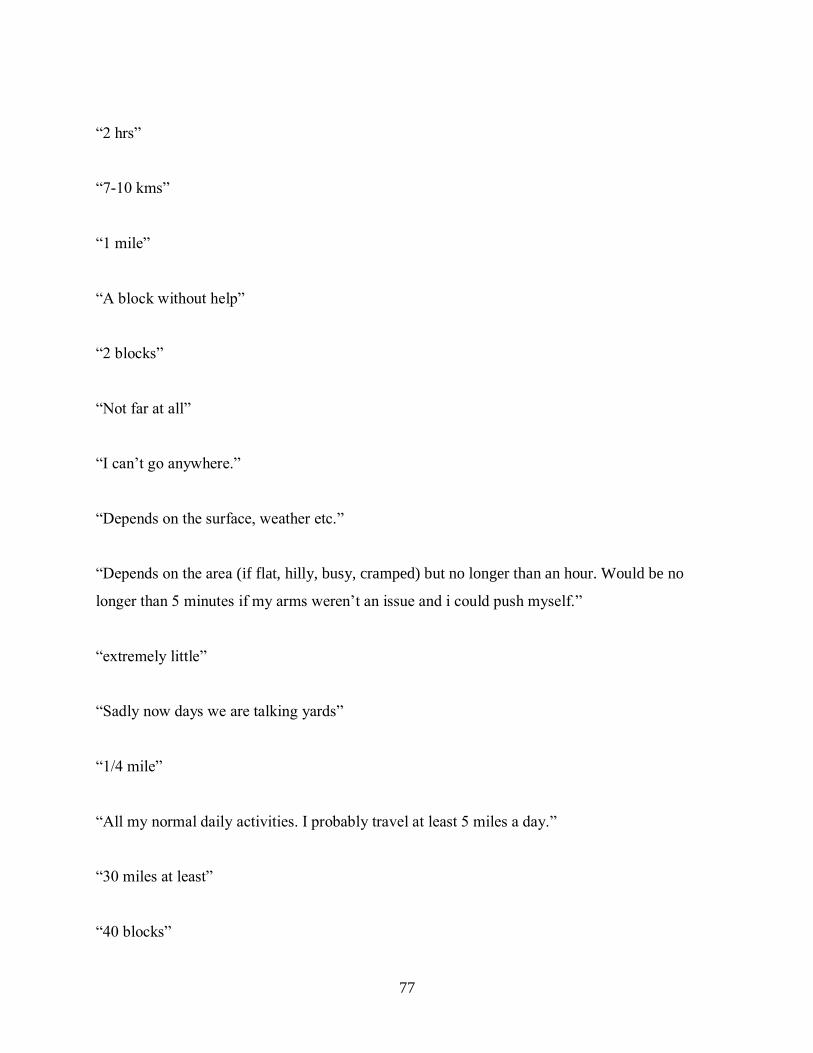
77
“2 hrs”
“7-10 kms”
“1 mile”
“A block without help”
“2 blocks”
“Not far at all”
“I can’t go anywhere.”
“Depends on the surface, weather etc.”
“Depends on the area (if flat, hilly, busy, cramped) but no longer than an hour. Would be no
longer than 5 minutes if my arms weren’t an issue and i could push myself.”
“extremely little”
“Sadly now days we are talking yards”
“1/4 mile”
“All my normal daily activities. I probably travel at least 5 miles a day.”
“30 miles at least”
“40 blocks”

78
“I cannot go any distance without assistance”
Question: How many hours of battery life would you like to see in an electric attachment?
“All day at least. It would be inconvenient to have to charge daily if don't have to. 48 hours.”
“It should at least last a full 16 hour day.”
“7”
“4+”
“At least 10 hours”
Question: What features would you like to see in an electric attachment?
“Easy to attach by self, no help required.”
“Reliable, lightweight, easy to put on and remove, can work in wet grass up and down hills like a
golf course.”
“easy detachability, lightweight (li-ion batteries), weatherproof, ability to wheely, easy to
freewheel (non-restrictive when turned off)”
“easy to get on and off for car and light enough to lift myself alone if necessary”
“Simple tooless attachment. Waterproof and cannot Increase the footprint or turn radius”
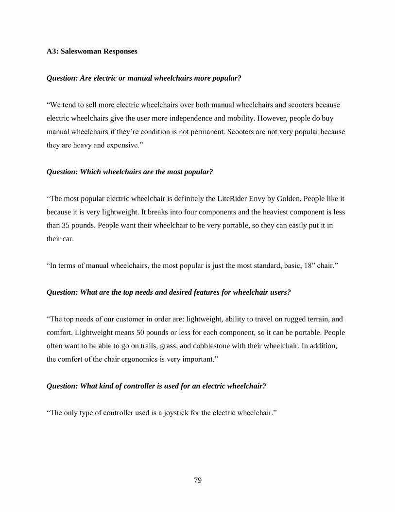
79
A3: Saleswoman Responses
Question: Are electric or manual wheelchairs more popular?
“We tend to sell more electric wheelchairs over both manual wheelchairs and scooters because
electric wheelchairs give the user more independence and mobility. However, people do buy
manual wheelchairs if they’re condition is not permanent. Scooters are not very popular because
they are heavy and expensive.”
Question: Which wheelchairs are the most popular?
“The most popular electric wheelchair is definitely the LiteRider Envy by Golden. People like it
because it is very lightweight. It breaks into four components and the heaviest component is less
than 35 pounds. People want their wheelchair to be very portable, so they can easily put it in
their car.
“In terms of manual wheelchairs, the most popular is just the most standard, basic, 18” chair.”
Question: What are the top needs and desired features for wheelchair users?
“The top needs of our customer in order are: lightweight, ability to travel on rugged terrain, and
comfort. Lightweight means 50 pounds or less for each component, so it can be portable. People
often want to be able to go on trails, grass, and cobblestone with their wheelchair. In addition,
the comfort of the chair ergonomics is very important.”
Question: What kind of controller is used for an electric wheelchair?
“The only type of controller used is a joystick for the electric wheelchair.”

80
Appendix B: Customer Needs Tables
Table B1: Hierarchical list of customer needs for power-assist product.
The device has a long battery life. The device’s battery can last a full day.
The device can be easily charged.
The device can be quickly charged.
The device enables off-road travel.
The device enables traveling on wet grass.
The device enables traveling up hills. The device enables traveling on a golf course.
The device enables travel on dirt/gravel/wet grass.
The device enables going on hiking trips. The device enables travel over obstacles like curbs.
The device is easy to operate. The device is easy to steer.
The device’s controls are conveniently located.
The device can be controlled by users with limited hand
dexterity. The device can be operated with one hand.
The device makes the wheelchair easy to maneuver.
The device keeps the user’s hands free for other tasks. The device allows traveling while simultaneously
holding objects in hand.
The device can be easily transported.
The device can be loaded/unloaded from a car by the
user without assistance from other people. The device is easy to handle.
The device can be transported in a regular vehicle
without a special lift.
The device maintains the wheelchair’s foldability.
The device allows manual propulsion when desired.
The device allows the wheelchair to be propelled manually when the battery runs out.
The device spins freely (no resistance) when off.
The device has mode for assisted manual propulsion.
The device is ergonomic.
The device can be operated when seated in a
comfortable position. The device enables propulsion of the wheelchair without
stressing users’ arms/back/shoulders.
The device’s controls are located near users’ normal hand positions when using manual wheelchairs.
The device is lightweight. The device can be lifted by user without assistance.
The device is easy to attach/detach. The device can be attached/detached without help from
another person.
The device can be attached without using tools. The device is compatible with a wide variety of manual
wheelchairs.
The device is compact.
The device does not increase footprint of wheelchair.
The device does not increase the turning radius of the
wheelchair. The device is foldable.
The device permits travel through narrow doorways.
The device allows the user to navigate the wheelchair in tight spaces.
The device allows the wheelchair to be used indoors.
The device functions in inclement weather. The device can be used in the rain.
The device is waterproof.
The device does not restrict the user’s movement.
The device allows easily getting on/off wheelchair.
The device permits the user to easily get into a car.
The device is reliable.
The device is easy to maintain. The device can operate for a long time before needing
maintenance.
The device is made of easily obtainable parts.
The device can be easily fixed.
The device is affordable.
The device is affordable for users with low incomes. The device is approved for purchase using
Medicare/Medicaid funds.
The device’s cost can be covered by insurance.
The device has a simple but useful user interface.
The device warns the user when the battery is low.
The device shows how much battery/range is left. The device controls are intuitive/easy to understand.
The device increases the user’s mobility. The device enables traveling further than would be
possible through manual propulsion alone.
The device enables the user to travel without assistance. The device has a long range.

81
Table B2: List of customer needs ranked by their relative importance, 5 being the highest and 1 the lowest.
# Need: The device... Mentioned by Rank
1 is affordable. Dr. Batdorf, Saleswoman, Facebook
users 5
2 enables off-road travel. Dr. Sparks, Saleswoman, Facebook
users 5
3 can be easily transported. Saleswoman, Facebook users 5
4 is durable/reliable. Dr. Sparks, Facebook users 4
5 is easy to operate. Facebook users 4
6 is lightweight. Saleswoman, Facebook users 4
7 has a long battery life. Facebook users 3
8 is easy to attach/detach. Saleswoman, Facebook users 3
9 increases the user’s mobility. Dr. Batdorf, Facebook users 3
10 is compact. Facebook users 3
11 is ergonomic. Saleswoman, Facebook users 2
12 does not restrict the user’s
movement. Facebook users 2
13 allows manual propulsion when
desired. Facebook users 2
14 functions in inclement weather. Facebook users 1
15 has a simple but useful user interface. Facebook users 1

82
Appendix C: Product Design Specifications
Table C1: Marginal and ideal values to define initial target specifications.
Metric Units Min Target Max
Max speed mph
Concrete/asphalt mph 4.5 5 5.5
Hard-packed dirt mph 3 4 5.5
Cobblestone/brick mph 3 4 5.5
Grass mph 2.5 3.5 5.5
Min speed mph
Concrete/asphalt mph -- 1 1.5
Hard-packed dirt mph -- 1 2
Cobblestone/brick mph -- 1 2
Grass mph -- 1 2
Max incline speed mph
8.3% grade mph 1 2 3.5
Time to attach device s
Seated in chair s -- 60 90
Standing behind chair s -- 45 75
Time to detach device s
Seated in chair s -- 45 75
Standing behind chair s -- 30 60
Range mi 3 5 --
Weight lbs -- 25 35

83
Appendix D: Timeline
The following figure is broken up into multiple pieces to properly fit on the page. It is the Gantt
chart that outlines the project schedule for Fall, Winter, and Spring quarter.

84
Figure F1: Full Gantt chart

85
Appendix E: Hand Calculations
E1: Drive Unit
Figure G1.1: Calculating wheelchair’s coefficient of rolling resistance. 4 pounds of force were required to push the
42.1 lb. wheelchair when loaded with an additional 90 lbs. (132.1 lbs. total), so the rolling resistance coefficient
was calculated to be 0.03 (FR = rolling resistance, FP = pushing force, m = mass, 𝜇R = rolling resistance
coefficient, g = gravitational acceleration, N = normal force).
Figure G2.2: The maximum incline the device must navigate is an 8.3% grade (1:12 rise/run ratio). In this scenario
the force required to push the wheelchair and a 200 lb. occupant (~250 combined lbs.) was calculated to 28 lbs (FR
= rolling resistance, FP = pushing force, m = mass, 𝜇R = rolling resistance coefficient, g = gravitational
acceleration, N = normal force).

86
Figure G3.3: This is the calculation for the force when slipping occurs if the trailing arm is not carrying the battery.
The force when slipping occurs is 19.0 lbs.

87
Figure G4.4: This is the calculation for the force when slipping occurs if the battery is placed on the trailing arm.
The force when slipping occurs is 65.7 lbs.
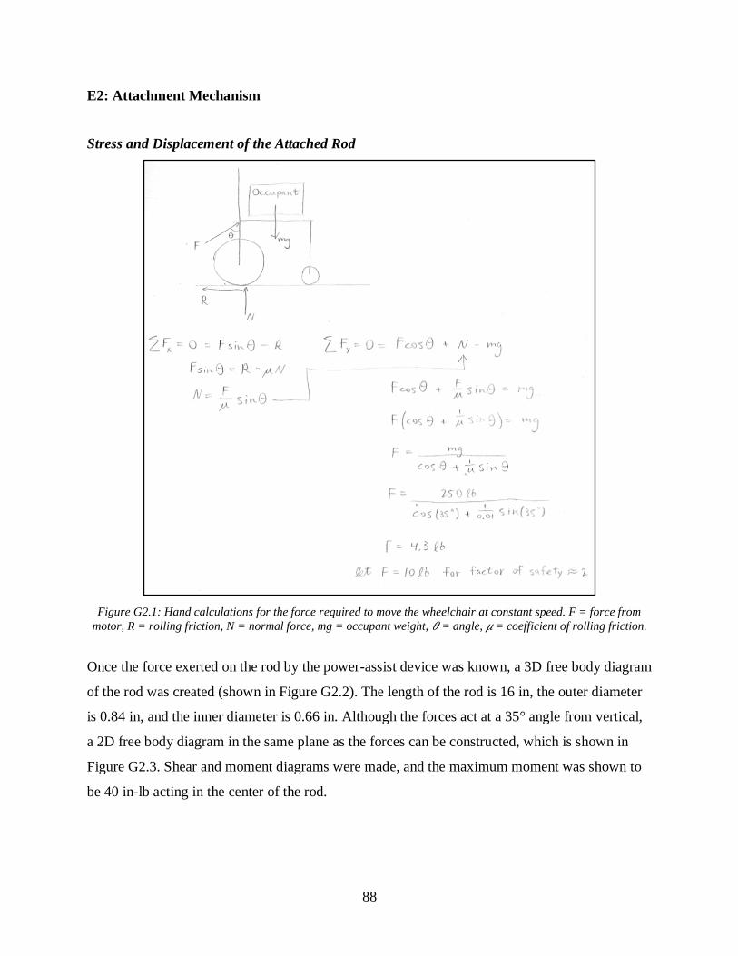
88
E2: Attachment Mechanism
Stress and Displacement of the Attached Rod
Figure G2.1: Hand calculations for the force required to move the wheelchair at constant speed. F = force from
motor, R = rolling friction, N = normal force, mg = occupant weight, 𝜃 = angle, 𝜇 = coefficient of rolling friction.
Once the force exerted on the rod by the power-assist device was known, a 3D free body diagram
of the rod was created (shown in Figure G2.2). The length of the rod is 16 in, the outer diameter
is 0.84 in, and the inner diameter is 0.66 in. Although the forces act at a 35° angle from vertical,
a 2D free body diagram in the same plane as the forces can be constructed, which is shown in
Figure G2.3. Shear and moment diagrams were made, and the maximum moment was shown to
be 40 in-lb acting in the center of the rod.

89
Figure H2.2: 3D free body diagram of the rod showing the force exerted by the motor acting in the middle and a
reaction force at each end where the rod is connected to the wheelchair frame.
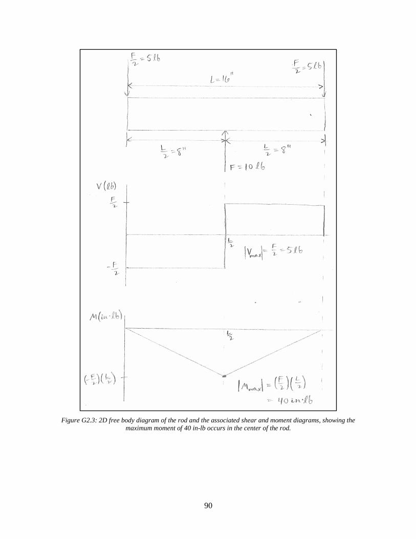
90
Figure G2.3: 2D free body diagram of the rod and the associated shear and moment diagrams, showing the
maximum moment of 40 in-lb occurs in the center of the rod.

91
Once the maximum moment was calculated, it was used to find the maximum bending stress in
the rod (displayed in Figure G2.4). The maximum bending stress was found to be 1.1 ksi, which
is well below the rod’s yield strength of 35 ksi.
Figure G2.4: Cross-section of the rod showing the plane in which the forces act, the neutral axis, and the locations
of maximum tension and compression due to the bending stress. The maximum bending stress was calculated to be
1.1 ksi, well below the rod’s yield strength.
Finally, the maximum deflection and von Mises stress were calculated to be 0.0014 in and 1.1
ksi respectively (shown in Figure G2.5).
Figure G2.5: Calculations for the maximum deflection of the rod (at the center) and the maximum von Mises stress.

92
E3: Battery
Maximum current, I:
Battery voltage = 36 V
Motor power draw = 200 W
𝑃 = 𝐼𝑉
𝐼 = 𝑃/𝑉 = 200𝑊/36𝑉 = 5.6 𝐴𝑚𝑝𝑠 (P = power, I = current, V = Voltage)
Required battery capacity, Q:
Target range = 5 miles
Target speed = 3 mph
𝑇 = 𝐷/𝑉 = 5𝑚𝑖/3𝑚𝑝ℎ = 1.67 ℎ𝑜𝑢𝑟𝑠 (T = time, D = distance, V = speed)
𝐸 = 𝑃𝑇 (E = battery energy)
𝑄 = 𝐸/𝑉 = (𝑃𝑇)/𝑉 = (200𝑊)(1.67ℎ)/(36𝑉) (Q = battery capacity)
𝑸 = 𝟗. 𝟑 𝐴𝑚𝑝 − ℎ𝑜𝑢𝑟𝑠

93
Appendix F: Decision Matrices
Table D1: Concept scoring matrix for attachment to chair designs
Concepts: Attachment to Chair
A
X-design
B
Clamp
C
Telescoping
rod
D
Pin
Reference
Smart Drive
Selection
criteria Weight Rating Score Rating Score Rating Score Rating Score Rating Score
Ease of
attachment 25% 1 0.25 5 1.25 2 0.5 5 1.25 4 1
Ease of
detachment 25% 1 0.25 5 1.25 2 0.5 5 1.25 4 1
Durability 10% 5 0.5 3 0.3 4 0.4 3 0.3 3 0.3
Ease of
manufacturing 15% 4 0.6 4 0.6 3 0.45 4 0.6 2 0.3
Foldability 25% 5 1.25 1 0.25 5 1.25 2 0.5 2 0.5
Top Score 2.85 3.65 3.1 3.9 3.1
Rank 4 2 3 1 -
Continue? No Yes Yes Yes -

94
Table D2: Concept scoring matrix for user control
Concepts: User Control
A
Boat Throttle
B
Joystick
C
Knob and Button
Reference
Electric
Wheelchair
Selection criteria Weight Rating Score Rating Score Rating Score Rating Score
Ergonomic 50% 4 2 3 1.5 5 2.5 3 1.5
Cruise control 20% 4 0.8 2 0.4 5 1 2 0.4
Durability 10% 3 0.3 4 0.4 5 0.5 4 0.4
Ease of
manufacturing 20% 3 0.6 3 0.6 4 0.8 3 0.6
Top Score 3.7 2.9 4.8 2.9
Rank 2 3 1 -
Continue? No No Yes -
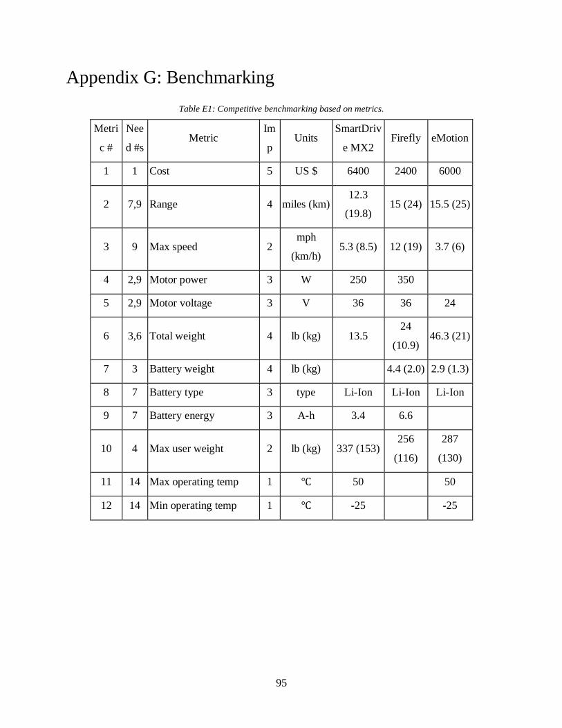
95
Appendix G: Benchmarking
Table E1: Competitive benchmarking based on metrics.
Metri
c #
Nee
d #s Metric
Im
p Units
SmartDriv
e MX2 Firefly eMotion
1 1 Cost 5 US $ 6400 2400 6000
2 7,9 Range 4 miles (km) 12.3
(19.8) 15 (24) 15.5 (25)
3 9 Max speed 2 mph
(km/h) 5.3 (8.5) 12 (19) 3.7 (6)
4 2,9 Motor power 3 W 250 350
5 2,9 Motor voltage 3 V 36 36 24
6 3,6 Total weight 4 lb (kg) 13.5 24
(10.9) 46.3 (21)
7 3 Battery weight 4 lb (kg) 4.4 (2.0) 2.9 (1.3)
8 7 Battery type 3 type Li-Ion Li-Ion Li-Ion
9 7 Battery energy 3 A-h 3.4 6.6
10 4 Max user weight 2 lb (kg) 337 (153) 256
(116)
287
(130)
11 14 Max operating temp 1 ℃ 50 50
12 14 Min operating temp 1 ℃ -25 -25

96
Appendix H: Raw Testing Data
Table H1: Speed testing data.
Surface Distance (ft) Time (sec)
Asphalt 17.5 3.39, 3.39, 3.39
Turf 36 7.44, 7.40, 7.40
Table H2: Range testing voltage data
Time (min) Voltage (V) Time (min) Voltage (V) Time (min) Voltage (V)
0 40.6 45 39.1 125 38.3
3 39.7 50 39 130 38.2
4 39.6 55 39.1 135 38.1
5 39.6 60 39.1 140 37.9
7 39.5 65 39.1 145 37.8
10 39.5 70 39 150 37.2
12 39.5 75 39 155 35.9
15 39.5 80 39 157 35.8
19 39.4 85 38.9 158 35
22 39.4 90 38.8 159 34.5
24 39.4 95 38.8 159.25 34.2
27 39.3 100 38.8 159.75 33.9
30 39.2 105 38.6 160 33.7
33 39.2 110 38.6 161 33
37 39.2 115 38.5
40 39.2 120 38.4

97
Table H3: Attachment testing data
Trial Time (sec)
1 51
2 50.29
3 38.5
4 33.49
5 52.23
6 30.41

98
Appendix I: Part Drawings
Figure I1: Assembly drawing

99
Figure I2: Pivot rod sheath drawing
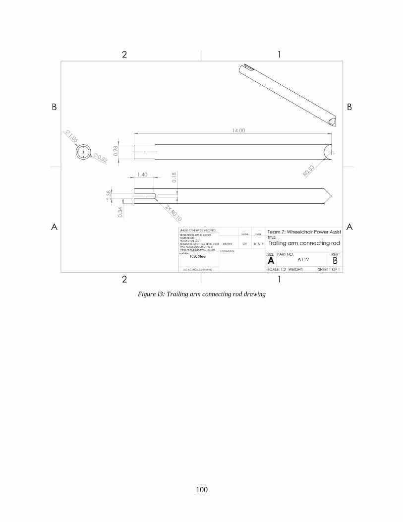
100
Figure I3: Trailing arm connecting rod drawing
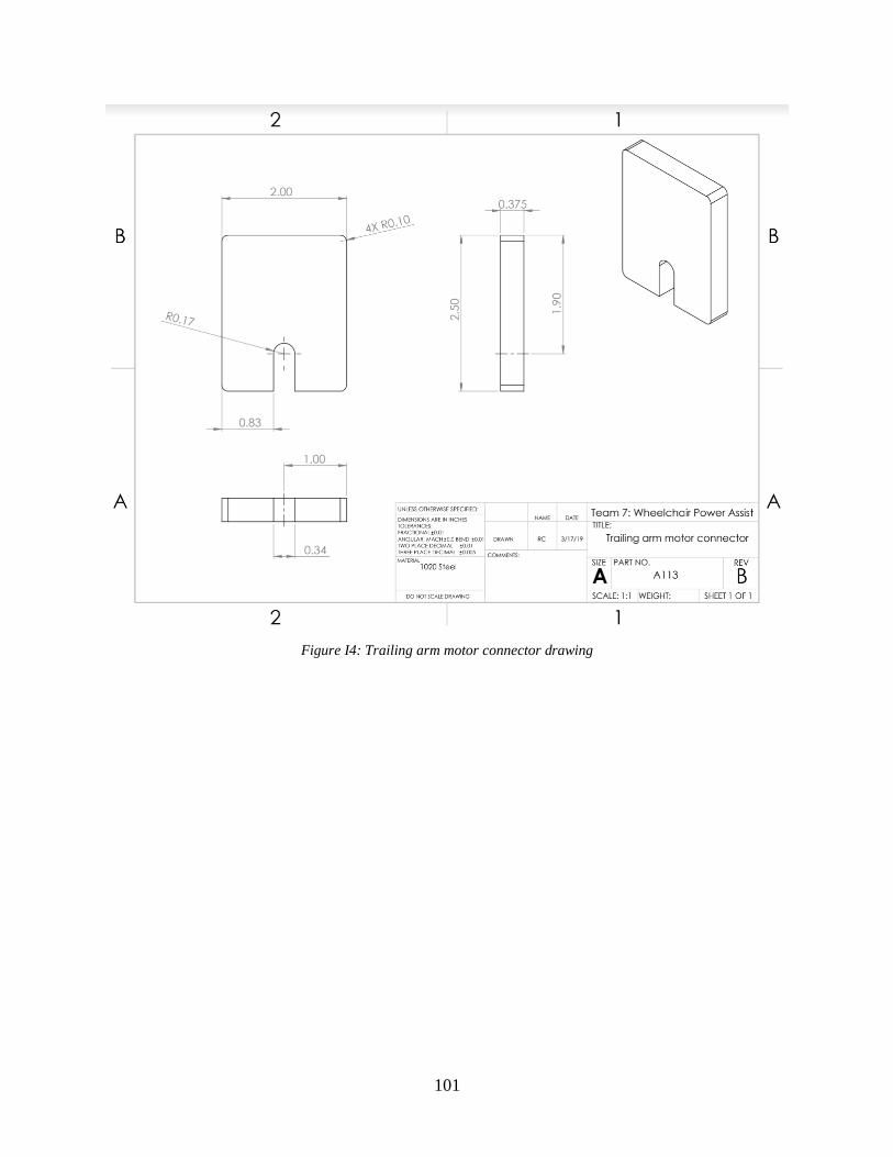
101
Figure I4: Trailing arm motor connector drawing

102
Figure I5: Battery plate drawing
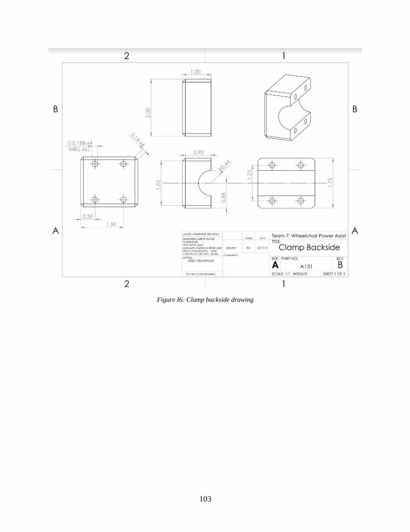
103
Figure I6: Clamp backside drawing
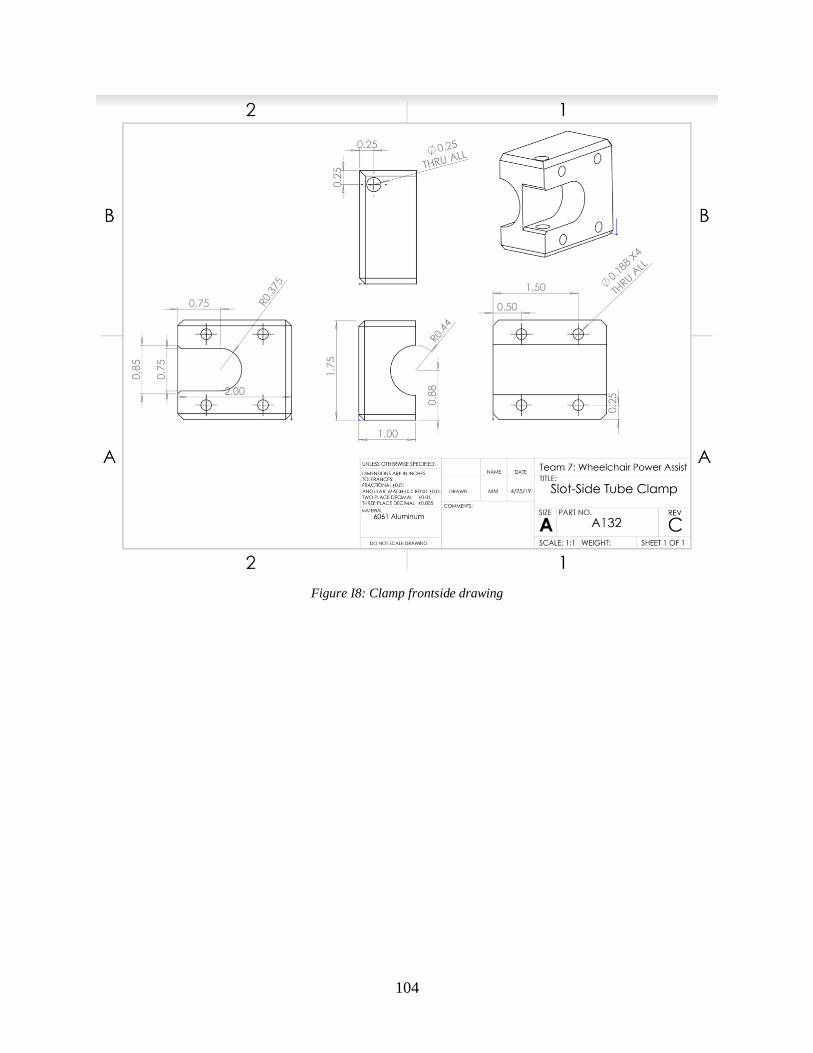
104
Figure I8: Clamp frontside drawing

105
Appendix J: Business Plan
Risks and Challenges: Experienced advisors to mitigate risks
The largest challenge that the power-assist product faces is the medical device approval process
through the FDA. This power-assist attachment is classified by the FDA as a Class II medical
device, so there are general and special controls as a means to regulate the product and its
market. The FDA’s general controls include but are not limited to: provisions that relate to
establishment registration and device listing; premarket notification; records and reports; and
good manufacturing practices. The Safe Medical Devices Act of 1990 added “special controls,”
which can include the promulgation of performance standards as well as postmarket surveillance,
patient registries, development and dissemination of guidelines (including guidelines for the
submission of clinical data in premarket notification submissions), and other appropriate actions
as FDA deems necessary to provide such assurance [35]. A potential consultant for the project,
Dr. Sparks is a surgeon and UCSD biomedical engineering faculty member with experience in
the biomedical device industry and with FDA approval process. With Dr. Sparks’ specialized
knowledge and expertise, the engineering team will be able to manage both the time and funding
required by the FDA approval process.
Financial risk management advising could initially be provided by a university business
professor who would provide pro-bono consulting for the medical device’s first year. This
advisor would guide us in interactions with initial investors and assist in the training of a full-
time financial executive.
Timeline, Budget, and ROI: Investment returns in the second year
The scope of this project is designing and building a fully-functioning device that can be retro-
fitted to a manual wheelchair and provide power-assist capabilities. Table J1 shows an
approximate Phase 1 timeline.
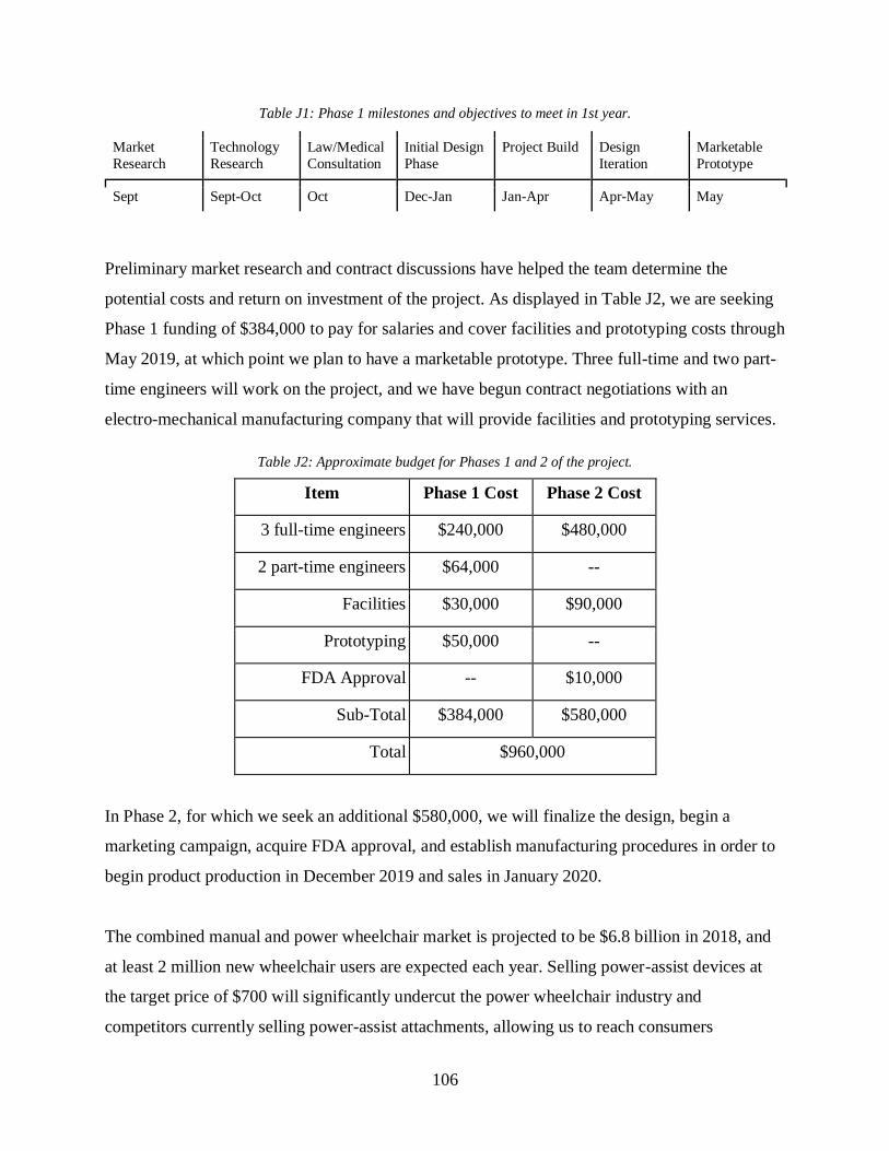
106
Table J1: Phase 1 milestones and objectives to meet in 1st year.
Market
Research
Technology
Research
Law/Medical
Consultation
Initial Design
Phase
Project Build Design
Iteration
Marketable
Prototype
Sept Sept-Oct Oct Dec-Jan Jan-Apr Apr-May May
Preliminary market research and contract discussions have helped the team determine the
potential costs and return on investment of the project. As displayed in Table J2, we are seeking
Phase 1 funding of $384,000 to pay for salaries and cover facilities and prototyping costs through
May 2019, at which point we plan to have a marketable prototype. Three full-time and two part-
time engineers will work on the project, and we have begun contract negotiations with an
electro-mechanical manufacturing company that will provide facilities and prototyping services.
Table J2: Approximate budget for Phases 1 and 2 of the project.
Item Phase 1 Cost Phase 2 Cost
3 full-time engineers $240,000 $480,000
2 part-time engineers $64,000 --
Facilities $30,000 $90,000
Prototyping $50,000 --
FDA Approval -- $10,000
Sub-Total $384,000 $580,000
Total $960,000
In Phase 2, for which we seek an additional $580,000, we will finalize the design, begin a
marketing campaign, acquire FDA approval, and establish manufacturing procedures in order to
begin product production in December 2019 and sales in January 2020.
The combined manual and power wheelchair market is projected to be $6.8 billion in 2018, and
at least 2 million new wheelchair users are expected each year. Selling power-assist devices at
the target price of $700 will significantly undercut the power wheelchair industry and
competitors currently selling power-assist attachments, allowing us to reach consumers

107
previously unable to afford more than a manual wheelchair. Table J3 summarizes the key
statistics used to estimate a $716,000 profit-margin after one year of sales.
Table J3: Estimated sales and ROI.
Amount
Unit selling Price $700
Per unit profit margin 20%
Total units sold 1st year 12,000
Gross income $1,680,000
Net profit $716,000
Net 1st year ROI $358,000
Half of the $716,00 first-year profit will go to Phase 1 and Phase 2 investors, resulting in a net
ROI of $358,000 by the end of of 2020.
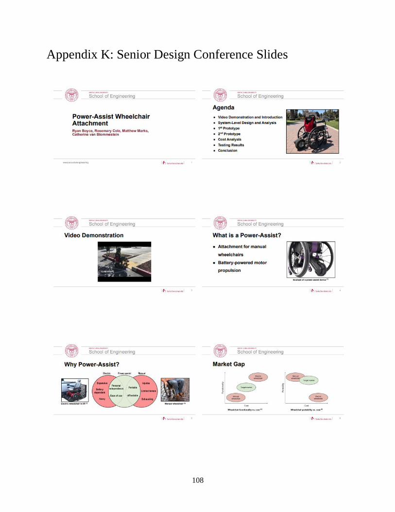
108
Appendix K: Senior Design Conference Slides
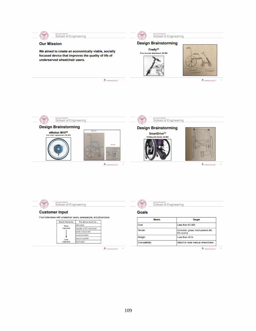
109

110

111

112

113
114

115
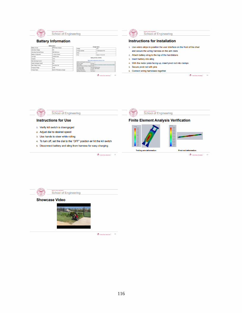
116