power break circuit breakers 800–2000 a frames, 240–600 vac
TRANSCRIPT

gPower Break® Circuit Breakers
800–2000 A Frames, 240–600 Vac
GEH–4693D
User’s Guide


i
GEH–4693D
WARNINGS, CAUTIONS, AND NOTESAS USED IN THIS PUBLICATION
WARNINGS
Warning notices are used in this publication to emphasize that hazardous voltages, currents, orother conditions that could cause personal injury or death are present in this equipment or may beassociated with its use.
Warning notices are also used for situations in which inattention or lack of equipment knowledgecould cause either personal injury or damage to equipment.
CAUTIONS
Caution notices are used for situations in which equipment might be damaged if care is not taken.
NOTES
Notes call attention to information that is especially significant to understanding and operatingthe equipment.
This document is based on information available at the time of its publication. While efforts havebeen made to ensure accuracy, the information contained herein does not cover all details or varia-tions in hardware and software, nor does it provide for every possible contingency in connectionwith installation, operation, and maintenance. Features may be described herein that are not pres-ent in all hardware and software systems. GE Industrial Systems assumes no obligation of notice t o holders of this document with respect to changes subsequently made.
GE Industrial Systems makes no representation or warranty, expressed, implied, or statutory, withrespect to, and assumes no responsibility for the accuracy, completeness, sufficiency, or usefulnessof the information contained herein. No warrantees of merchantability or fitness for purpose shallapply.
The following are trademarks of GE Company:
Power Break®, MicroVersaTrip Plus™ , MicroVersaTrip PM™, MagneTrip™, MicroVersaTrip®
© 1998 GE CompanyAll Rights Reserved

Power Break® Circuit Breakers
Table of Contents
ii
Chapter 1. Receiving and Installation1–1 Overview................................................................................................................................ 11–2 Receiving the Breaker ............................................................................................................. 1
Storage ............................................................................................................................ 11–3 Installation............................................................................................................................. 1
Bolted Electrical Connections ............................................................................................ 1Breaker Mounting............................................................................................................. 1
Chapter 2. Breaker Operation2–1 Standard Features................................................................................................................... 32–2 Operating Instructions ............................................................................................................ 3
Sequence of Operations..................................................................................................... 3Operating Instructions for Manually Charged Breakers........................................................ 4Operating Instructions for Electrically Charged Breakers ..................................................... 4Wiring Notes .................................................................................................................... 5Application Notes ............................................................................................................. 6
2–3 Trip Unit Setup ...................................................................................................................... 6MicroVersaTrip® and MicroVersaTrip® RMS-9 Trip Units.................................................. 6MagneTrip™ Trip Units.................................................................................................... 9MicroVersaTrip Plus™ and MicroVersaTrip PM™ Trip Units............................................... 9
Chapter 3. Accessories3–1 Introduction .........................................................................................................................103–2 Circuit Breaker Cover.............................................................................................................10
Breaker Cover Removal ....................................................................................................10Breaker Cover Reassembly ................................................................................................11
3–3 Shunt Trip Device..................................................................................................................12Mounting Plate Removal ..................................................................................................12Shunt Trip Installation.....................................................................................................13Mounting Plate Installation ..............................................................................................13
3–4 Undervoltage Release Device ..................................................................................................14UVR Installation..............................................................................................................14
3–5 Blown-Fuse Trip Device..........................................................................................................15Blown-Fuse Trip Device Installation...................................................................................16
3–6 Auxiliary Switch.....................................................................................................................16Auxiliary Switch Installation .............................................................................................17
3–7 Remote Close Solenoid and Remote Charge Indication ............................................................183–8 Optional Features ..................................................................................................................18
Limited Close Access Button.............................................................................................18Padlock Function.............................................................................................................19
Chapter 4. Maintenance4–1 Inspections............................................................................................................................204–2 Lubrication ...........................................................................................................................20

Power Break® Circuit Breakers
List of Figures and Tables
iii
Figures
1. Circuit breaker with lifting straps in place. ............................................................................................... 1
2. Location of mounting bolt inserts on 800 A frame breakers ....................................................................... 1
3. Location of mounting bolt inserts on 1600–2000 A frame breakers. ............................................................ 2
4. Manually charged breaker. ..................................................................................................................... 3
5. Motor operator-charged breaker. ............................................................................................................ 3
6. Motor operator charged breaker with the top cover removed. .................................................................... 3
7. Bell alarm wiring to prevent continuous cycling of the automatic charging mechanism. .............................. 5
8. Wiring for optional bell alarm lockout applications................................................................................... 5
9. Tap changer cards. ................................................................................................................................ 6
10. Cover and trip unit removed from the breaker ......................................................................................... 7
11. Neutral CT connection for four-wire ground fault..................................................................................... 7
12. Wiring diagram for MicroVersaTrip and MicroVersaTrip RMS-9 trip units with ground fault on atop-fed four-wire load. ............................................................................................................................ 8
13. Wiring diagram for MicroVersaTrip and MicroVersaTrip RMS-9 trip units with ground fault on abottom-fed four-wire load. ...................................................................................................................... 8
14. Releasing the trip unit interlock to remove or install the trip unit............................................................... 8
15. Aligning the trip unit to the mounting plate. ........................................................................................... 9
16. Adjusting the settings on a MagneTrip trip unit........................................................................................ 9
17. 800 A frame electrically operated breaker................................................................................................10
18. 1600–2000 A frame electrically operated breaker. ....................................................................................11
19. 1600–2000 A frame electrically operated breaker with the outer cover removed. .........................................11
20. Wire ties on the accessory leads and mounring plate insulator. .................................................................11
21. Crossbar hook engaging the drive hook. .................................................................................................11
22. Shunt trip device with cut-off switch........................................................................................................12
23. Shunt trip wiring diagram. ....................................................................................................................12
24. Locations of the mounting plate retaining screws, isolation barrier, and molded drive crank.......................12
25. Shunt trip coil position with no blown-fuse trip device..............................................................................13
26. Shunt trip coil position with blown-fuse trip device. .................................................................................13
27. Attaching the switch bracket to the arm stop. ..........................................................................................13
28. Undervoltage release device. ..................................................................................................................14
29. Dropping resistor supplied with 240–600 V UVRs.....................................................................................14
30. UVR wiring diagram. ............................................................................................................................14
31. Slide reset lever and spring on the mounting plate...................................................................................15
32. Positioning the UVR assembly on the mounting plate. .............................................................................15
33. Installing the UVR mounting screw. .......................................................................................................15
34. Blown-fuse trip device accessory..............................................................................................................15
35. Blown-fuse trip device wiring diagram.....................................................................................................16
36. Auxiliary switch. ...................................................................................................................................16
37. Auxiliary switch wiring diagram. ............................................................................................................17

Power Break® Circuit Breakers
List of Figures and Tables
iv
38. Trip unit removed from the breaker. ......................................................................................................17
39. Installing the auxiliary switch assembly. ..................................................................................................17
40. Securing the auxiliary switch assembly. ...................................................................................................17
41. Wiring diagram for remote charge indication. ........................................................................................18
42. Wiring diagram for remote charge indication with remote close solenoid..................................................18
43. Limited close access button....................................................................................................................18
44. OFF button padlock with panel door interlock. .......................................................................................19
45. Defeating the OFF button padlock. ........................................................................................................19
Tables
1. Weights of the various breaker frame sizes, with and without a motor operator............................................ 1
2. Bolt sizes and mounting torques for bus connections. ............................................................................... 1
3. Sequence of operations that may be performed with Power Break circuit breakers ....................................... 4
3. Application data for control power. ......................................................................................................... 5
4. Accessory lead color codes .....................................................................................................................10
5. Shunt Trip electrical characteristics........................................................................................................12
6. UVR electrical characteristics.................................................................................................................14
7. Auxiliary switch electrical characteristics.................................................................................................17
8. Catalog numbers and ratings for the remote close solenoid ......................................................................18

Power Break® Circuit Breakers
Chapter 1. Receiving and Installation
1
1–1 Overview
The Power Break® line of insulated-case circuit breakersis designed to protect low-voltage power circuits andequipment. Current models are offered with Magne-Trip™, MicroVersaTrip Plus™, and MicroVersaTrip PM™trip units for fault detection.
1–2 Receiving the Breaker
Unpack the circuit breaker and inspect it for shippingdamage. Ensure that the breaker has the proper current,voltage, and interruption ratings for the application.
The weights of the various frame sizes are listed in Table1, for reference. Figure 1 shows a breaker with straps forlifting.
CCCCAAAAUUUUTTTTIIIIOOOONNNN:::: Do not attempt to lift the circuit breaker byits operating handle.
FrameRating, A Type Weight, lbs
800 ManualElectric
5064
1600 ManualElectric
8296
2000 ManualElectric
88102
Table 1. Weights of the various breaker frame sizes, with andwithout a motor operator.
Figure 1. Circuit breaker with lifting straps in place.
Storage
The breaker should be placed in service immediately in itspermanent location. However, if it must be stored for anindefinite period, it should be carefully protected against
condensation, preferably by storage in a warm, dry room.Circuit breakers for outdoor equipment should be storedin that equipment only when power is available and heat-ers are in operation, to prevent condensation.
The breaker should be stored in a clean location, freefrom corrosive gases or fumes. In particular, protect thebreaker from moisture and cement dust, as that combina-tion may be corrosive.
If the breaker is stored for any length of time, it should beinspected periodically to ensure good mechanical condi-tion.
1–3 Installation
Bolted Electrical Connections
Using an industry-accepted solvent, remove any foreignmaterial from the line and load strap surfaces and thecorresponding surfaces of connecting bus and terminalstuds. Ensure that the mating surfaces are smooth andfree of burrs and nicks.
Place the bus connections in position and align themounting holes. Insert and fasten the mounting bolts andwashers according to the specifications in Table 2.
Bus ConnectionBreaker Frame, A Bolt Dia. Torque, in-lbs
800 (1) 1/2 in 3001200–1600 (2) 1/2 in 300
2000 (4) 1/2 in 300
Table 2. Bolt sizes and mounting torques for bus connections.
Breaker Mounting
For mounting the circuit breaker, use the four 1/4-20 x 1/2-inch-deep inserts in the back of the breaker. The locationsof the inserts are shown in Figures 2 and 3 for the twoframe sizes. Tighten the mounting bolts to 50 in-lb.
Figure 2. Location of mounting bolt inserts on 800 A frame breakers.

Power Break® Circuit Breakers
Chapter 1. Receiving and Installation
2
Figure 3. Location of mounting bolt inserts on 1600–2000 A framebreakers.

Power Break® Circuit Breakers
Chapter 2. Breaker Operation
3
2–1 Standard Features
Power Break circuit breakers are equipped with the follow-ing standard features. The letters are keyed to the breakerillustrations in Figures 4, 5, and 6.
AAAA Indicator ON – RedCHG (manual) – yellowCHARGED (electrical) – yellowOFF – Green
BBBB ON button
CCCC OFF button
DDDD Manual charging handle
EEEE Lockable manual charge engagement button (motoroperated only)
FFFF Terminal board (motor operator drive unit)
GGGG Removable protective window
JJJJ CT tap setting indicator (MicroVersaTrip only)
KKKK Removal protective trip unit cover (Magnetrip™only)
LLLL Cover mounting screws (four)
MMMM Midcover mounting screws (three – motor operatedonly)
NNNN MicroVersaTrip RMS-9 trip unit interchangeable rat-ing plug
OOOO Motor operator control circuit fuses
PPPP MicroVersaTrip RMS-9 test set connection port
Figure 4. Manually charged breaker.
Figure 5. Motor operator-charged breaker.
Figure 6. Motor operator charged breaker with the top coverremoved.
2–2 Operating Instructions
Sequence of Operations
The sequence of operations that may be performed on thecircuit breaker is listed in Table 3.

Power Break® Circuit Breakers
Chapter 2. Breaker Operation
4
IndicatorMain Breaker
ContactsCondition of
Charging Springs Next Permissible Operating FunctionOFF Open Discharged Mechanism may be charged
CHARGED / CHG Open Fully Charged Contacts may be closedON Closed Discharged Contacts may be opened
Table 3. Sequence of operations that may be performed with Power Break circuit breakers.
Operating Instructions for Manually
Charged Breakers
Charging the Mechanism Springs
Rotate the operating handle counter-clockwise until thehandle stops (about 120° ). Rotate the handle clockwiseback to its home position. This operation will NOT closethe contacts and turn the breaker ON. The indicator willdisplay CHG.
CCCCAAAAUUUUTTTTIIIIOOOONNNN:::: If the breaker latch is held in the trippedposition by any of the following accessories, themechanism springs will discharge at the end of thecharging stroke and the breaker will revert to the OFF
condition.
• The key interlock or padlock is in the locked OFF con-dition.
• On a draw-out breaker, the draw-out interlock isengaged with the carriage in any position except TEST
or ENGAGED.
• The bell alarm lockout was not reset after an overcur-rent lockout.
• The undervoltage release is not energized.
These conditions must be corrected before the breakercan be closed. Failure to do so may result in equipmentdamage.
Closing the Breaker
Close the breaker contacts with either of the followingmethods:
• Depress the ON button on the breaker escutcheon.
• Energize the (optional) remote close accessory byconnecting terminal 5 to terminal 6.
Opening the Breaker
Open the breaker contacts with either of the followingmethods:
• Depress the PUSH OFF button on the breakerescutcheon.
• Energize the (optional) shunt trip accessory or deen-ergize the (optional) undervoltage release accessory.
Operating Instructions for Electrically
Charged Breakers
Charging the Mechanism Springs
Charge the mechanism springs with either of the follow-ing methods:
• Local– Depress the lockable manual charge engagement
button until it is flush with the handle surface.Slight rotation of the handle may be necessary tofully depress the button in order to align theinternal coupling.
– Hold the button down and rotate the operatinghandle counter-clockwise until the handle stops(about 120°). Rotate the handle clockwise back toits home position. This operation will NOT closethe contacts and turn the breaker ON. Theindicator will display CHARGED.
• Remote – Connect terminal 3 to terminal 4 toenergize the motor operator mechanism.
Closing the Breaker
Close the breaker contacts with either of the followingmethods:
• Depress the ON button on the breaker escutcheon.
• Energize the (optional) remote close accessory byconnecting terminal 5 to terminal 6.
Opening the Breaker
Open the breaker contacts with either of the followingmethods:
• Depress the PUSH OFF button on the breakerescutcheon.
• Energize the (optional) shunt trip accessory or deen-ergize the (optional) undervoltage release accessory.
Automatic Operation
For automatic closing of the breaker when the springs arecharged, permanently connect terminal 5 to terminal 6.The breaker will close as soon as the charging cycle iscomplete.
For automatic charging of the closing springs, perma-nently connect terminal 3 to terminal 4. The springs will

Power Break® Circuit Breakers
Chapter 2. Breaker Operation
5
charge as soon as the breaker is opened, whether from afault trip or from being intentionally opened.
CCCCAAAAUUUUTTTTIIIIOOOONNNN:::: Do not wire breakers for both automaticcharge and automatic close unless a bell alarm withovercurrent lockout is incorporated. Otherwise, thebreaker may repeatedly close into an overcurrent fault.
CCCCAAAAUUUUTTTTIIIIOOOONNNN:::: The bell alarm lockout and undervoltagerelease both hold the breaker latch open when activated.To prevent continuous cycling (see Application Notes)when the breaker is wired for automatic charging, inter-connect the bell alarm switch to the motor operator ter-minal board as shown in Figures 7 and 8.
NNNNOOOOTTTTEEEE:::: The motor operator contains a feature that shutsoff control power if the OFF button is held depressed.Thus, electrical operation is prevented if a key interlockor padlock accessory is applied in the breaker OPEN con-dition. If the breaker is equipped with a draw-out inter-lock (TPDO-1), electrical operation is permitted only ifthe draw-out carriage is in the ENGAGED or TEST posi-tion.
Figure 7. Bell alarm wiring to prevent continuous cycling of theautomatic charging mechanism.
Figure 8. Wiring for optional bell alarm lockout applications.
Wiring Notes
Observe the following notes when wiring the breaker foroperation:
• Customer-supplied contacts (such as CHARGE andCLOSE) should be momentary action, rated for 0.25A at 125 Vdc for dc motor operators or rated for 3 Aat 120 Vac for ac motor operators.
• Do not apply power to any terminal board pointother than points 1 and 2.
• Observe the proper polarity for dc motor operators(point 1 is positive).
• When performing hi-pot or dielectric tests:– Remove all power leads, both control and power.– Short all motor operator terminal board points.– Open the circuit breaker.– Test between the motor operator terminal board
points and the load side of the breaker’s centerpole (this pole is connected to the frame).
– Test at 2200 Vac for one minute using a current-limited, nondestructive ac hi-pot tester withmaximum output of 20 mA.
Operating Motor Current, A Close Nominal Maximum MaximumRated
VoltageVoltageRange
LockedRotor
FullLoad Average
Solenoid,peak A
Fuses (SloBlo 125 V)
ChargeTime , s
CloseTime, s
OpeningTime, s
120 Vac 102–132 8 2.5 1.5 3.0 2 A 5.0 0.83 0.05125 Vdc 100–140 10 2.5 1.5 3.5 2 A 6.0 0.83 0.0572 Vdc 57–81 13 3.0 2.0 5.0 3 A 6.0 0.83 0.0548 Vdc 38–58 20 5.0 2.5 6.6 4 A 6.0 0.83 0.0524 Vdc 19–29 24 7.0 3.0 13.2 6.25 A 7.5 0.83 0.05
Table 3. Application data for control power.

Power Break® Circuit Breakers
Chapter 2. Breaker Operation
6
Application Notes
• Size the control power source according to theinformation in Table 3. If a single source is to supplyseveral motor operators, it must be sized appropri-ately. Where breakers are wired for automaticcharge, it may be necessary to supply power to severalmotor operators simultaneously during start up.
• The control power source should be sized so that thedrop in voltage from no load to full load does notexceed 7%.
• Acceptable dc power sources are the following:– dc generator,– battery,– three-phase, full-wave rectified ac, or– any other dc power source with a peak-to-peak
ripple voltage of not more than 15% of the ratedvoltage at motor full-load current.
• Breakers built after approximately June 1978 areequipped with an anticycling circuit that will lock outthe breaker if the latch fails to reset (such as due to adeenergized UVR). Lockout occurs if the chargetime exceeds 20 seconds. Reset a locked-out breakerlocally by pushing the OFF button or remotely bymomentarily removing control power from themotor operator.
2–3 Trip Unit Setup
NNNNOOOOTTTTEEEE:::: MicroVersaTrip RMS-9 trip unit rating plugs maybe changed per GEH-5369 and GEH-5371 without void-ing the UL listing. MicroVersaTrip trip units and tapchanger cards may be installed or replaced per GEH-4657 and this manual without voiding the UL listing.MicroVersaTrip Plus and MicroVersaTrip PM trip unitsand rating plugs may be changed or replaced per GEH-6273 without voiding the UL listing.
MicroVersaTrip® and MicroVersaTrip®
RMS-9 Trip Units
Trip settings are installed at the factory with minimumvalues on all functions. Customers will generally want toadjust settings to their own requirements.
Adjusting Trip Settings
Use the following procedure to adjust trip settings onthese trip units:
1111.... Remove the clear plastic protective window, shown inFigure 4.
2222.... Change the settings by twisting the indicator switchesto the desired values or multipliers. See GEH-4657 fordefinitions of MicroVersaTrip functions and GEH-5369 for MicroVersaTrip RMS-9 functions.
3333.... Reinstall the window.
Rating Plugs
MicroVersaTrip RMS-9 trip units require the installationof a rating plug in accordance with GEH-5369 and GEH-5371 to set the maximum continuous current rating.
Tap Changer Card
Some MicroVersaTrip models include a tap changer card,shown in Figure 9. When provided, this function allowsthe customer to change the rating of the breaker frame.
Figure 9. Tap changer cards.

Power Break® Circuit Breakers
Chapter 2. Breaker Operation
7
All breakers provided with tap cards are shipped with bothHIGH (100% of the current rating Sensor Amp on thebreaker name plate) and low (50–75% of the currentrating Sensor Amp on the breaker name plate). The low
card is packed and supported on the breaker handle. Thehigh card is installed in the breaker frame. To changesettings use the following procedure:
WWWWAAAARRRRNNNNIIIINNNNGGGG:::: The circuit breaker must be removed fromthe electrical system before attempting any operationsthat involve removing the breaker’s cover.
1111.... Turn the breaker off.
2222.... Remove the four cover mounting screws and removethe top cover. On motor operator-equipped breakers,remove only the top cover.
3333.... Withdraw the card from the tap changer support andreplace with the other card, as shown in Figure 10.The print on the top of the card should be orientedthe same as the breaker cover name plate.
Figure 10. Cover and trip unit removed from the breaker.
4444.... Trip units providing ground fault protection mustalso have the tap setting changed on the tapped neu-tral CT (four-wire systems). Change the black wirelead from the high or low terminal to match thedesired tap setting of the breaker frame, as shown inFigure 11.
5555.... Replace the breaker cover.
6666.... Operate the breaker manually through thecharge–close–open cycle to ensure that the breaker isproperly functioning mechanically before energizingor connecting it to the electrical system.
NNNNOOOOTTTTEEEE:::: A deenergized undervoltage release will not allowthe mechanism to charge and close.
7777.... Store the extra tap card in a convenient place.
Figure 11. Neutral CT connection for four-wire ground fault.
Neutral Current Transformer (Four-Wire Ground
Fault System)
Ground fault protection is offered as an optional functionof the MicroVersaTrip® trip unit. However, all MicroVer-saTrip-generation breaker frames are provided with ter-minal board points for connection to a neutral CT. Donot short these terminals if there is no neutral CTconnected.
Always match the rating of the CT to the rating of the cir-cuit breaker; specifically, use the following criteria:
• Fixed-rated breaker frames – match the neutral CTamp rating to the breaker sensor amp rating.
• Tapped or high/low-rated breaker frames – matchthe neutral CT amp rating to the high/low setting ofthe breaker sensor amp rating.
Note that MicroVersaTrip RMS-9-equipped breakers arenot available with inverted construction (formerly desig-nated by Cat. No. suffix B). These breakers may be eithertop fed, as illustrated in Figure 12, or bottom fed, as illus-trated in Figure 13.
NNNNOOOOTTTTEEEE:::: The neutral CT is mounted in reverse in Figure13 when the breaker is bottom (reverse) fed.
CCCCAAAAUUUUTTTTIIIIOOOONNNN:::: Match the tapped terminal for the black leadto the tap setting, if provided, on the breaker frame.
CCCCAAAAUUUUTTTTIIIIOOOONNNN:::: Observe the polarity markings on the neutralCT shell and the breaker frame.
CCCCAAAAUUUUTTTTIIIIOOOONNNN:::: When a neutral CT is not used or notrequired (three-wire ground fault), do not short theground fault terminal points on the breaker frame.Leave them open as supplied by the factory.

Power Break® Circuit Breakers
Chapter 2. Breaker Operation
8
Figure 12. Wiring diagram for MicroVersaTrip and MicroVersaTripRMS-9 trip units with ground fault on a top-fed four-wire load.
Figure 13. Wiring diagram for MicroVersaTrip and MicroVersaTripRMS-9 trip units with ground fault on a bottom-fed four-wire load.
MicroVersaTrip RMS-9 Trip Units
The trip units on MicroVersaTrip RMS-9-equipped break-ers are not interchangeable. The breaker rating may beadjusted by changing the rating plug installed in the faceof the trip unit. See GEH-5369 and GEH-5371 for instruc-tions.
MicroVersaTrip Trip Units
MicroVersaTrip-equipped breakers were ordered completeor as a frame and trip unit only. Some trip units andframes have rejection schemes to prevent mismatching offunctions.
The limits of interchangeability are as follows:
• High short-time or H-function trip units may not beused in frames that are not wired for H function(special CTs).
• Special trip units for AK breakers with the M (noinstantaneous) function may not be used with PowerBreak breakers.
Refer to GEH-4657 for installation or replacement ofMicroVersaTrip trip units with remote overload indicationand for recommended wiring for zone-selective interlock.
To change or install trip units without remote indication,use the following procedure.
WWWWAAAARRRRNNNNIIIINNNNGGGG:::: The circuit breaker must be removed fromthe electrical system before attempting any operationsthat involve removing the breaker’s cover.
1111.... Remove the four cover-mounting screws and removethe top cover. On motor-operated breakers, removeonly the top cover to replace the trip unit.
2222.... Remove the trip unit as follows:aaaa.... Push in the trip unit-cover interlock, as illustrated
in Figure 14.bbbb.... Lift the trip unit off the mounting plate and ter-
minal plug.cccc.... The trip unit-cover interlock will now swing out
and lock over the base to prevent reinstallation ofthe breaker cover when no trip unit is installed.
Figure 14. Releasing the trip unit cover interlock to remove or installthe trip unit.

Power Break® Circuit Breakers
Chapter 2. Breaker Operation
9
3333.... Install the replacement trip unit as shown in Figure15:aaaa.... Align the holes in the bottom of the trip unit with
the guide pins in the mounting plate. Lower thetrip unit until it is fully down on the mountingplate and the connecting plug is secure.
bbbb.... Push in the trip unit-cover interlock until it locksin place, as shown in Figure 14.
NNNNOOOOTTTTEEEE:::: The trip unit has a stud on the bottom to defeatthe trip unit-cover interlock locking spring.
Figure 15. Aligning the trip unit to the mounting plate.
4444.... Replace the top cover and secure with the four cover-mounting screws.
5555.... Operate the breaker manually through thecharge–close–open cycle to ensure that the breaker isproperly functioning mechanically before energizingor connecting it to the electrical system.
NNNNOOOOTTTTEEEE:::: A deenergized undervoltage release will not allowthe mechanism to charge and close.
6666.... For trip units with ground fault, a neutral CT must beprovided if a four-wire system is to be used. See thesection on neutral CTs for instructions and precau-tions. Do not short the ground fault terminals pro-vided on the breaker frame if a neutral CT is notused.
MagneTrip™ Trip Units
Use the following procedure to change trip settings onMagneTrip trip units:
1111.... Remove the protective trip unit cover.
2222.... Change the trip setting by rotating the plastic buttonsin the base with a screw driver, as shown in Figure 16.
3333.... Replace the protective cover.
Figure 16. Adjusting the settings on a MagneTrip trip unit.
MicroVersaTrip Plus™ and MicroVersaTrip
PM™ Trip Units
See GEH-6273 for detailed instructions for setting upMicroVersaTrip Plus and MicroVersaTrip PM trip units.

Power Break® Circuit Breakers
Chapter 3. Accessories
10
3–1 Introduction
These instructions cover the field installation of internallymounted electrical accessories. They are UL listed for usein all 800–2000 A frame Power Break® circuit breakerswith MicroVersaTrip® trip units. These accessories mayalso be installed in 800–1600 A frame Power Break break-ers with MagneTrip™ trip units, but the UL listing isvoided.
The control leads of internally mounted accessories exit inpigtail form from the side of the breaker. These leads areterminated at the secondary disconnect points of draw-outbreakers or at optional terminal blocks when specified forstationary-mounted breakers. All leads are color coded aslisted in Table 4.
Accessory Lead ColorNo. ofLeads
Shunt Trip Black 2UndervoltageRelease
Blue 2
Auxiliary SwitchWhite – common
Red – OPEN (NO)Brown/White – CLOSED (NC)
3 perswitch
Bell Alarm(OvercurrentLockout)
Yellow – commonPurple – CLOSED (NC)Brown – OPEN (NO)
3
Blown-Fuse Trip(3-Coil Shunt Trip)
Line End Load End Phase Red Brown-White ABlue White B
Yellow Black C
6
Closing Solenoid(Manual Breakersonly)
White – commonBlack – remote indicationOrange – remote close
3
Table 4. Accessory lead color codes.
3–2 Circuit Breaker Cover
Before any accessories can be installed in a Power Breakcircuit breaker, the cover(s) must be removed, asdescribed in the following sections.
WWWWAAAARRRRNNNNIIIINNNNGGGG:::: Before installing any accessories, completelyde-energize the circuit breaker and disconnect it fromthe electrical circuit. This is mandatory, since thebreaker must be ON during certain stages of installationand testing.
CCCCAAAAUUUUTTTTIIIIOOOONNNN:::: Do not turn the breaker upside down, sinceloose parts may become lost.
NNNNOOOOTTTTEEEE:::: All breakers are equipped with mechanical inter-locks that automatically trip the breaker when the coveris removed with the breaker closed.
Breaker Cover Removal
Manual Breaker
Use the following procedure to remove the cover of amanually operated breaker:
1111.... Press the off button to open the circuit breaker.
2222.... Remove the four cover-mounting screws.
3333.... Remove the breaker cover.
Electrically Operated Breaker
Use the following procedure to remove the cover of anelectrically operated breaker. An 800 A frame breaker isshown in Figure 17 and a 1600–2000 A frame breaker isshown in Figure 18.
1111.... Press the off button to open the circuit breaker.
2222.... Disconnect all external leads from the terminalboard.
3333.... Remove the four cover mounting screws.
4444.... Remove the outer cover.
5555.... On 1600-2000 A framer breakers only, remove the twoinner-cover mounting screws, as shown in Figure 18.
6666.... Loosen the captive inner-cover lock screw, as shownin Figure 19.
7777.... Remove the inner cover.
Figure 17. 800 A frame electrically operated breaker.

Power Break® Circuit Breakers
Chapter 3. Accessories
11
Figure 18. 1600–2000 A frame electrically operated breaker.
Figure 19. 1600–2000 A frame electrically operated breaker with theouter cover removed.
Breaker Cover Reassembly
Manually Operated Breakers
1111.... Verify that all connections are secure and the breakeris free of debris.
2222.... Verify that the breaker is off.
CCCCAAAAUUUUTTTTIIIIOOOONNNN:::: Verify that the accessory mounting plateinsulator, shown in Figure 20, is properly located so itwill not be damaged when the cover is replaced. Thecover phase barrier must pass to the right side of thisinsulator.
3333.... Position the charging handle at the home position (6o’clock) on the cover. Align the cover mountingscrew holes with the breaker base and install the fourcover screws. Tighten the screws to 50–60 in-lbs.
Figure 20. Wire ties on the accessory leads and mounting plateinsulator.
Electrically Operated Breakers
1111.... Verify that all connections are secure and the breakeris free of debris.
CCCCAAAAUUUUTTTTIIIIOOOONNNN:::: Verify that the accessory mounting plateinsulator is properly located, as shown in Figure 26.
2222.... Slide the inner cover assembly onto the breaker base.Ensure that the crossbar hook engages the drive stud,as shown in Figure 21.
Figure 21. Crossbar hook engaging the drive hook.
3333.... Tighten the inner cover lock screw, shown in Figure19, to 10 in-lbs.
4444.... On 1600–2000 A frame breakers only, replace the twoinner cover mounting screws and tighten to 50–60 in-lbs.
Power Break® Circuit Breakers
Chapter 3. Accessories
12
5555.... Position the charging handle at the home position (6o’clock) on the outer cover. Align the outer cover-mounting screw holes with those on the inner coverand install the four cover-mounting screws. Tightento 50–60 in-lbs.
NNNNOOOOTTTTEEEE:::: Ensure that the control terminal board properlyengages the cover retaining slots.
6666.... Connect the control and power wiring as per theinstructions supplied with the circuit breaker.
3–3 Shunt Trip Device
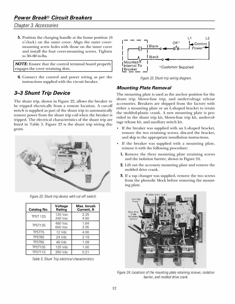
The shunt trip, shown in Figure 22, allows the breaker tobe tripped electrically from a remote location. A cut-offswitch is supplied as part of the shunt trip to automaticallyremove power from the shunt trip coil when the breaker istripped. The electrical characteristics of the shunt trip arelisted in Table 5. Figure 23 is the shunt trip wiring dia-gram.
Figure 22. Shunt trip device with cut-off switch.
Catalog No.VoltageRating
Max. InrushCurrent, A
TPST 12S 120 Vac240 Vac
2.254.50
TPST13S 480 Vac600 Vac
1.642.05
TPST7S 12 Vdc 4.00TPST8S 24 Vdc 2.18TPST9S 48 Vdc 1.09TPST10S 125 Vdc 1.00TPST11S 250 Vdc 0.21
Table 5. Shunt Trip electrical characteristics.
Figure 23. Shunt trip wiring diagram.
Mounting Plate Removal
The mounting plate is used as the anchor position for theshunt trip, blown-fuse trip, and undervoltage releaseaccessories. Breakers are shipped from the factory witheither a mounting plate or an L-shaped bracket to retainthe molded-plastic crank. A new mounting plate is pro-vided in the shunt trip kit, blown-fuse trip kit, undervol-tage release kit, and auxiliary switch kit.
• If the breaker was supplied with an L-shaped bracket,remove the two retaining screws, discard the bracket,and skip to the appropriate installation instructions.
• If the breaker was supplied with a mounting plate,remove it with the following procedure:
1111.... Remove the three mounting plate retaining screwsand the isolation barrier, shown in Figure 24.
2222.... Lift out the accessory mounting plate and remove themolded drive crank.
3333.... If a tap changer was supplied, remove the two screwsfrom the phenolic block before removing the mount-ing plate.
Figure 24. Locations of the mounting plate retaining screws, isolationbarrier, and molded drive crank.

Power Break® Circuit Breakers
Chapter 3. Accessories
13
Shunt Trip Installation
NNNNOOOOTTTTEEEE:::: If the shunt trip is being replaced because of adefective coil, the cause of the initial failure should firstbe determined. If necessary, consult the factory for fur-ther guidance.
1111.... Assemble the coil to the mounting plate as shown inFigure 25. If a blown-fuse trip device is also to beinstalled on the mounting plate, mount the shunttrip coil as shown in Figure 26.
2222.... When a blown-fuse trip device is included, place theshunt trip plunger stop nut in contact with theplunger of the blown-fuse trip device.
3333.... Depress the actuator on the cut-off switch. Align thetapped holes in the switch bracket with the holes inthe arm stop (left pole) and secure with #8-32 × 9/16screws and lock washers, as shown in Figure 27.Tighten to 23 in-lbs torque.
4444.... Remove the knockouts in the side of the base, asrequired. Each knockout will accommodate up tothree bundles of wire. Remove all sharp edges with afile.
5555.... Clean all debris from the inside of the breaker.
NNNNOOOOTTTTEEEE:::: Shunt trip coils rated at 12 Vdc or 24 Vdc must bemounted in the position nearest the latch. These coilsmay not develop enough force to drive both the latchand the blown-fuse trip device.
Figure 25. Shunt trip coil position with no blown-fuse trip device.
Mounting Plate Installation
1111.... Replace the molded drive crank onto the mechanismdrive pin, as shown in Figure 24, engaging the rollpins into the slot in the drive crank.
Figure 26. Shunt trip coil position with blown-fuse trip device.
Figure 27. Attaching the switch bracket to the arm stop.
2222.... Place the mounting plate in position so that its twooperating studs engage the molded drive crank, asshown in Figure 24. Ensure that the isolating barrieris in place.
3333.... Attach the three retaining screws. Tighten the twosmall screws to 20 in-lbs and the large screw with tub-ing to 75 in-lbs.
4444.... Attach wire ties to the leads and secure them to themounting plate, as shown in Figure 20.
5555.... Insert the leads into the knockout in the base sidewall, ensuring that one tie is on the inside of the baseand the other is on the outside.
6666.... Apply the descriptive label to the front of the breakercover.

Power Break® Circuit Breakers
Chapter 3. Accessories
14
3–4 Undervoltage Release Device
The undervoltage release device (UVR), shown in Figure28, opens the circuit breaker when the supply voltagedrops to 35–60% of its rated value. Figure 29 shows thedropping resistor supplied with 240–600 volt UVRs. TheUVR electrical characteristics are listed in Table 6. TheUVR wiring diagram is in Figure 30.
Figure 28. Undervoltage release device.
Figure 29. Dropping resistor supplied with 240–600 V UVRs.
Figure 30. UVR wiring diagram.
CatalogNumber
VoltageRating
ContinuousCurrent, mA
DroppingResistor*
TPUV1S 120 Vac 25 noneTPUV2S 240 Vac 25 5000 ?, 25 WTPUV2S 480 Vac 25 15,000 ?, 50 WTPUV6S 600 Vac 25 20,000 ?, 50 WTPUV7S 12 Vdc 211 noneTPUV8S 24 Vdc 104 noneTPUV9S 48 Vdc 54 noneTPUV10S 125 Vdc 24 noneTPUV11S 250 Vdc 24 5000 ?, 25 W
* Ohmite Type 270
Table 6. UVR electrical characteristics.
UVR Installation
1111.... Remove the circuit breaker cover(s) as describedabove in 3–2 Circuit Breaker Cover.
2222.... The UVR assembles to a mounting plate. Not allbreakers are shipped from the factory with a mount-ing plate. Some breakers have only an L-shapedbracket to retain the molded-plastic crank. A mount-ing plate is provided in the UVR kit.• If the breaker is supplied with an L-shaped
bracket, remove the two retaining screws and dis-card the bracket. Follow the Mounting PlateInstallation instructions and continue on to step3.
• If the breaker is supplied with a mounting plate,continue with step 3.
3333.... Remove the slide reset lever spring from the mount-ing plate, as shown in Figure 31. Be careful not tonick or damage the spring in any way, since it will beneeded for reassembly.
4444.... Push the latch and slide reset lever forward to pro-vide mounting clearance for the UVR assembly.
5555.... Position the UVR assembly mounting bracket so thatits retaining hole engages the latch pivot post, asshown in Figure 32.
6666.... Line up the UVR bracket’s mounting hole with thetapped hole in the accessory mounting plate. Installthe screw and lock washer, as shown in Figure 33.Tighten the screw to 9–11 in-lbs.
7777.... Replace the slide reset lever spring, shown in Figure31.
8888.... Remove the knockouts in the side of the base, asrequired. Each knockout will accommodate up tothree bundles of wire. Remove all sharp edges with afile.
9999.... Remove all debris from the inside of the breaker.

Power Break® Circuit Breakers
Chapter 3. Accessories
15
Figure 31. Slide reset lever and spring on the mounting plate.
Figure 32. Positioning the UVR assembly on the mounting plate.
11110000.... Use the wire ties provided to secure the leads to themounting plate and to secure the wire bundle to theinside and outside of the breaker base, as shown inFigure 20.
11111111.... Reassemble the breaker covers as described inBreaker Cover Reassembly.
11112222.... Mount the dropping resistor (when supplied) andMOV, shown in Figure 29. Wire these as shown inFigure 30.
Figure 33. Installing the UVR mounting screw.
11113333.... Perform the following functional check of the UVR:aaaa.... Apply rated voltage to the UVR coil.bbbb.... Turn the breaker on.cccc.... Reduce the control voltage. The breaker should
trip when the voltage drops to 35–60% of its ratedvalue.
11114444.... Apply the UVR descriptive label to the left side of thebreaker near the lead-exit area.
3–5 Blown-Fuse Trip Device
The blown-fuse trip device (three-coil shunt trip), shownin Figure 34, is intended for applications with breakersand fuses in series. This accessory prevents single-phasingconditions by monitoring the fuses and automaticallytripping the circuit breaker when a fuse blows. It does notprotect from single-phasing of the power source.
Figure 34. Blown-fuse trip device accessory.

Power Break® Circuit Breakers
Chapter 3. Accessories
16
Each coil of the blown-fuse trip device is wired across afuse so that the voltage across an open fuse is fed back tothe accessory coil. When the coil is energized, the solenoidcore releases the spring-biased latch, allowing the slide torotate the breaker latch, tripping the breaker. The fusemust be replaced and the breaker reset before the breakercan be reclosed.
If the breaker is closed on an open fuse, the blown-fusetrip device will automatically open the breaker.
Blown-Fuse Trip Device Installation
Installation of the blown-fuse trip device is similar to thatof the shunt trip, described above.
1111.... The blown-fuse trip device assembles to a mountingplate. Not all breakers are shipped from the factorywith a mounting plate. Some breakers have only anL-shaped bracket to retain the molded-plastic crank.A mounting plate is provided in the blown-fuse kit.• If the breaker is supplied with an L-shaped
bracket, remove the two retaining screws and dis-card the bracket.
• If the breaker is supplied with a mounting plate,follow the instructions under Mounting PlateRemoval.
2222.... Assemble the blown-fuse trip device to the accessorymounting plate as shown in Figure 26. If a shunt triphad previously been mounted as shown in Figure 25,it must be relocated as shown in Figure 26, with itsplunger stop nut in contact with the plunger of theblown-fuse trip device.
3333.... Follow the procedure for Mounting Plate Installation.
4444.... Perform the following installation checks:aaaa.... Replace the breaker cover as described above.
Close the breaker contacts.bbbb.... Apply 120 volts to one coil of the blown-fuse trip
device for not more than one second. Thebreaker must trip. Repeat the test for each coil.
5555.... Attach the six lead wires from the blown-fuse tripdevice across the three fuses, as shown in the wiringdiagram in Figure 35.
6666.... Apply the descriptive label to the front of the breaker.
7777.... Reassemble the breaker cover(s) as described inBreaker Cover Reassembly.
Figure 35. Blown-fuse trip device wiring diagram.
3–6 Auxiliary Switch
The auxiliary switch, shown in Figure 36, is used forremote indication of the breaker’s main contact posi-tion—open or closed. No distinction is made betweenopen or tripped mode. A maximum of 12 switches can beinstalled per breaker. Each is single-pole, double-throw(AB-type) and rated as listed in Table 7. Two switch posi-tions must be devoted to each shunt trip accessory (ifused) per breaker. The auxiliary switch wiring diagram isshown in Figure 37.
Figure 36. Auxiliary switch.

Power Break® Circuit Breakers
Chapter 3. Accessories
17
Figure 37. Auxiliary switch wiring diagram.
CatalogNumber
Number ofSwitch Elements
MaximumCurrent Rating
TPAS2ABx 1–126 A at 240 Vac
.25 A at 250 Vdc
.50 A at 125 Vdc
* Replace x with a number from 1–12 forthe number of switch elements.
Table 7. Auxiliary switch electrical characteristics.
Auxiliary Switch Installation
1111.... Remove the circuit breaker cover(s) as described inBreaker Cover Removal.• If the breaker was supplied with an L-shaped
bracket (see Mounting Plate Removal), removethe two retaining screws, discard the bracket, andinstall the mounting plate provided in the kit (seeMounting Plate Installation).
2222.... Both the left and right breaker poles can accept up tosix auxiliary switches. If the left pole contains a shunttrip, two of the six auxiliary switch positions must beused for the cut-out switches; thus, only four auxil-iary switches may be used in the left pole.
3333.... If auxiliary switches are to be installed in the rightpole, remove the trip unit by depressing the lockrelease lever while lifting up on the trip unit. Removethe trip unit mounting plate, shown in Figure 38.
4444.... Position the auxiliary switch assembly so that thetapped mounting holes on its bracket line up withthe through holes in the arm stop, as shown inFigure 39.
5555.... Secure the auxiliary switch assembly to the arm stopwith two #8 × 9/16 screws and lock washers, as shownin Figure 40. Tighten the screws to 23 in-lbs.
Figure 38. Trip unit removed from the breaker.
Figure 39. Installing the auxiliary switch assembly.
Figure 40. Securing the auxiliary switch assembly.
6666.... Remove knockouts in the side of the base, asrequired. Each knockout will accommodate up tothree bundles of wire. Remove all sharp edges with afile.
7777.... Use the supplied wire ties to secure the leads asshown in Figure 20.
8888.... Replace the trip unit mounting plate and trip unit.
9999.... Replace the breaker cover(s) as described in CircuitBreaker Cover Reassembly.
11110000.... Perform the following functional checks:aaaa.... With the breaker off, use a continuity tester to
verify continuity between the white and brown-

Power Break® Circuit Breakers
Chapter 3. Accessories
18
white leads. Verify an open circuit between thered and white leads.
bbbb.... With the circuit breaker on, the auxiliary switchcontacts should change sense.
11111111.... Apply the auxiliary switch descriptive label to thefront of the breaker cover.
3–7 Remote Close Solenoid and
Remote Charge Indication
The remote close solenoid is included with electricallyoperated breakers and may be ordered as a factory-installed option in manually operated breakers. Catalognumbers and specifications are listed in Table 8.
Remote charge indication provides for remote indicationthat the breaker closing springs are charged. Catalognumbers are TPXCAS and TSXCAS for 800–2000 A andfor 3000–4000 A frames, respectively. The switch is ratedat 15 A for 250 Vac and at 0.5 A for 125 Vdc. Figure 41 isthe wiring diagram for remote charge indication. Figure42 is the wiring diagram for remote charge indicationwith a remote close solenoid.
Figure 41. Wiring diagram for remote charge indication.
Figure 42. Wiring diagram for remote charge indication with remoteclose solenoid.
Catalog No.Rated
VoltageOperatingRange*, V
Current at Max.Voltage, A
MaximumClosing Time, s
MaximumOperating Time, s
TPXCC12S 120 Vac 102–132 3.3 0.083 0.050
TPXCC14S 240 Vac 204–264 1.7 0.083 0.050
TPXCC08S 24 Vdc 19–29 13 0.083 0.050
* The power source must stay within the rated operating voltage range of the close solenoid from no load to the full peakcurrent rating of the device.
Table 8. Catalog numbers and ratings for the remote close solenoid.
3–8 Optional Features
Special features may be ordered as specific accessories oras an integral part of the breaker catalog number. Refer tothe BuyLog®, GEP-1100, for these features.
Limited Close Access Button
This accessory, shown in Figure 43, provides for limitedmanual access to the ON button. The breaker can beclosed in an emergency for maintenance by inserting a1/8-inch diameter pin or rod into the hole in the center ofthe button. Manually operated breakers must be orderedwith an accessory closing solenoid.
Figure 43. Limited close access button.

Power Break® Circuit Breakers
Chapter 3. Accessories
19
Padlock Function
Handle Button Lock
A standard feature on motor-operated breakers that pre-vents manual charging of the mechanism, as shown inFigure 5.
OFF Button Padlock with Door Interlock
This accessory prevents opening of the panel door whenthe breaker is ON or CHARGED. It operates as follows:
• With the breaker OFF the paddle can be rotatedcounterclockwise over the breaker nameplate to clearthe enclosure panel door. Rotate the paddle clock-wise to lock the door, as shown in Figure 44.
• To defeat the interlock when the breaker is ON orCHARGED, depress the spring and rotate the paddleto clear the door, as shown in Figure 45.
Figure 44. OFF button padlock with panel door interlock.
Figure 45. Defeating the OFF button padlock.

Power Break® Circuit Breakers
Chapter 4. Maintenance
20
WWWWAAAARRRRNNNNIIIINNNNGGGG:::: Before beginning any maintenance work,disconnect the breaker from all voltage sources, bothpower and control, and ensure that the breaker is OFF.
4–1 Inspections
Circuit breakers should be maintained through theimplementation of a systematic maintenance program. Aperiodic inspection routine is recommended. The fre-quency of inspection should depend on the environ-mental conditions of each breaker. All circuit breakersshould be inspected at least annually. It a breaker is oper-ated frequently or installed in an area of high humidity,dust, or dirt, the frequency of maintenance inspectionsshould be increased. Under extremely adverse conditions,monthly inspections are recommended.
The maintenance inspection should begin with an overallvisual check. If dirt, grease, or any other foreign materialis found on or in the breaker, it should be thoroughly andcarefully removed. Do not use solvents on insulating mate-rial.
A rotating program providing for a periodic withdrawalfrom service of each breaker in turn for inspection andmaintenance is an excellent means of establishing a highlevel of service reliability. In such cases, one or more sparebreakers and all accessories should be available during themaintenance inspection to replace any breaker that maybe removed for repairs.
NNNNOOOOTTTTEEEE:::: When ordering spare parts, always enclose com-plete information from the breaker name plate, includ-ing the breaker’s serial number.
4–2 Lubrication
Moderate lubrication is all that is required for most circuitbreakers. Mechanical bearing points and sliding surfacesshould be lubricated at the regular inspection periodswith a thin film of molybdenum disulfide (Molykote G) orMobil 28 grease. GE recommends the use of kerosene forremoving hardened grease and dirt from the latch andbearing surfaces. All excess lubricant should be removedto avoid any contamination of dirt or dust.
CCCCAAAAUUUUTTTTIIIIOOOONNNN:::: Under no circumstances should lubricant beapplied to contact areas.


gGE Industrial Systems
General Electric Company41 Woodford Ave., Plainville, CT 06062
GEH4693 R05 0998 © 1998 General Electric Company