power cubes - wärtsilä
TRANSCRIPT

POWER CUBES

2

MAXIMIZED PREFABRICATION FOR MINIMIZED BUSINESS RISKThe Cubes are complete, fully functional power
plants with all the auxiliaries and components
that a power production unit requires.
The scope of supply is a cubical
construction with radiators on the roof and
an exhaust gas stack either situated close to
the cube or integrated within it. Each cube is
delivered complete with all the components
and structures located above ground. Only the
concrete foundation on which the assembly
rests is built locally, thus significantly reducing
the customer’s responsibility.
FAST, FUNCTIONAL AND FLEXIBLEFor industrial self-generation, small utilities
and IPP customers who do not have major
PACKED TO PERFECTION
ADVANTAGES OF CUBE DESIGN:
• Validated and reliable technical solutions
• High electrical efficiency through minimization of the plant’s own consumption
• Compact design and a minimized annex system
• Fluent and cost-efficient project execution from planning to start-up
• Optimized lifetime support and reduced warranty costs
• Future expansion flexibility.
construction and project-handling resources,
a complete power production unit requiring
minimum work on site is the answer. The
installation of a Power Cube is rapid and easy.
Plant start-up is fast thanks to pre-configured
software and interface solutions. Operation
and maintenance require a minimum of staff
on site and remote monitoring is possible.
Trouble-shooting is quick and spare part
availability is good. All this due to advanced
standardization.
The standardized design of the Power
Cubes also lifts the concept of “step-wise”
investment to new heights. Starting with just
a single Cube, you can easily expand the
installation by adding new, interconnected
Cubes. As the demand for power grows so will
your plant.
Are you looking for a great package deal for
power generation in the 5-30 MW range?
With our OilCube and GasCube power
generation solutions for smaller power
plants, you enjoy the same big benefits
as our customers for large turnkey power
plants: proven technical and logistical
solutions and reliable delivery schedules
guaranteed by a single supplier.
The Wärtsilä Power Cubes are modular,
pre-engineered single-engine power plants
produced within a cost framework that
justifies turnkey deliveries for small plants
while still complying with the needs of
different clients and applications.
GasCube BONTANG, INDONESIAType ......................................BaseloadEngines ............. 2 x Wärtsilä 16V34SGTotal output ........................... 13.9 MWFuel ...................................Natural gasDelivered..................................... 2009
3

WÄRTSILÄ OILCUBETThe Wärtsilä OilCube is a complete single-
unit power plant. The 20V32 engine version
is designed to meet a power demand of 5 to
30 MW. 12 and 16 cylinder engine versions
are also available as options.
The design of the Wärtsilä OilCube is
compact. Nevertheless, it includes a modular
heavy fuel oil (HFO) treatment system
consisting of two separators and a tank with
separated fuel.
Electrically heated and without a steam
system, the electricity consumption in a
Wärtsilä OilCube plant is minimized by utilizing
heat taken from the engine cooling water and
lubrication oil systems. A closed-circuit cooling
water system keeps the need for water down
to a minimum. And radiators placed on the
roof ensure the most effi cient cooling in all
circumstances.
Power Cubes have a low-voltage electrical
system inside the cube that includes a plant
programmable logic control (PLC) and a
panel mounted WOIS™ (Wärtsilä Operator’s
Interface System). Thus, the plants can be
monitored and operated remotely or by using
WOIS™ workstations.
4

1. Wärtsilä 20V32 engine2. OilCube Auxiliary module3. OilCube Treatment module4. Maintenance water tank5. Air compressor, 7 bar
6. Starting air compressor7. Ventilation intake louvre8. Intake air filter9. Starting air vessel
10. Charge air silencer
11. Exhaust gas silencer12. Cooling radiators13. Exhaust stack14. Expansion vessel15. Oil mist separator
16. Overhead crane17. Generator ventilation duct18. Generator19. Ventilation outlet fan
Oil Cube – Wärtsilä 3237 x 14 mArea: 518 m2
OilCube power outputsTechnical data 50 Hz/750 rpm 12V32 16V32 20V32
Power, electrical kW 5327 7124 8924
Heat rate kJ/kWh 7840 7815 7799
Electrical effi ciency % 45.9 46.1 46.2
Technical data 60 Hz/720rpm
Power, electrical kW 5211 6970 8730
Heat rate kJ/kWh 7840 7815 7799
Electrical effi ciency % 45.9 46.1 46.2
Dimensions and weight (generating set with liquids and 150 mm high spring elements)
Length mm 10030 11240 12200
Width mm 3050 3300 3300
Height mm 4420 4340 4420
Weight tonne 92 119 130
Heat rate and electrical effi ciency at generator terminals, including engine-driven pumps. ISO 3046 conditions and LHV. Tolerance 5%. Power factor 0.8.
MAIN TECHNICAL DATA
Engines ........................................................................................ Wärtsilä 12V32, 16V32, 20V32
Ambient temperature ................................................................................................... 0…+40 °C
Noise level ........................................................................................................... 70 dB(A) 100 m
OilCube auxiliary module .................................................................Fuel booster with massfl ow
Prelubrication oil pump
HT preheater
Thermostatic valves
Sludge collection
OilCube treatment module ............................................................................2 x HFO separators
Heater HFO/HT water
Separated fuel tank
LO separator
Control system local ......................................... Control panel with remote monitoring as option
Cooling radiator ....................................................................Single circuit, low noise on the roof
Ventilation ........................................................................................................Free in, forced out
Max temperature inside power house ...............................................................................+50 °C
5

WÄRTSILÄ GASCUBEThe Wärtsilä GasCube is a complete one-engine
power plant, based on the Wärtsilä 20V34SG,
with all the auxiliaries and components needed
to make up a working power production unit,
providing up to 10 MWe per unit.
The Wärtsilä GasCube consists of a
cubical enclosure that has the engine and the
alternator located on a common baseframe.
The inlet air module, charge air silencers,
exhaust gas system and an auxiliary module
are all connected to the genset.
The auxiliary module includes a gas-
regulating unit, the cooling system, an
instrument air system, and an engine pre-heater.
All auxiliaries are located in the modules.
The radiators for engine cooling are
installed on the roof of the enclosure. The
starting air vessel and the maintenance water
tank are installed next to the auxiliary module.
The only major component not located on the
auxiliary module is the starting air compressor
next to it.
The closed-circuit cooling systems used
in the GasCube make it the perfect choice for
remote locations or any location in which water
is scarce.
All Wärtsilä gas power plants are also
designed to give full output and high
performance in hot and dry conditions, as well
as at high altitudes.
New possibilities for Cube placement are
opened up by the Cube’s simple interface and
small footprint. A typical storage yard of an
industrial company, for example, would be more
than adequate as a location for this compact
solution offering excellent power density.
6
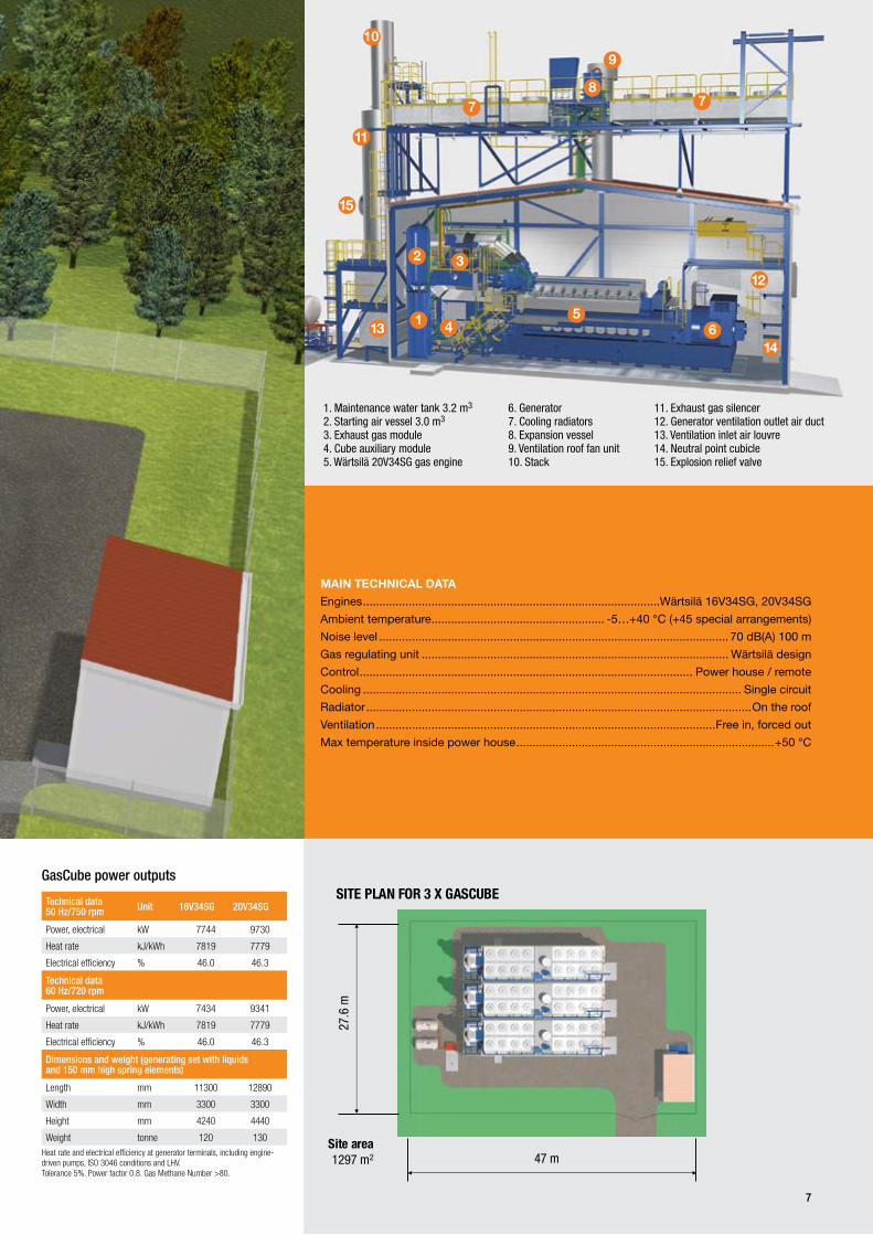
1. Maintenance water tank 3.2 m2. Starting air vessel 3.0 m3. Exhaust gas module4. Cube auxiliary module5. Wärtsilä 20V34SG gas engine
3
36. Generator7. Cooling radiators8. Expansion vessel9. Ventilation roof fan unit10. Stack
11. Exhaust gas silencer12. Generator ventilation outlet air duct13. Ventilation inlet air louvre14. Neutral point cubicle15. Explosion relief valve
MAIN TECHNICAL DATA
Engines ...........................................................................................Wärtsilä 16V34SG, 20V34SG
Ambient temperature ..................................................... -5…+40 °C (+45 special arrangements)
Noise level ........................................................................................................... 70 dB(A) 100 m
Gas regulating unit .............................................................................................. Wärtsilä design
Control ...................................................................................................... Power house / remote
Cooling .................................................................................................................... Single circuit
Radiator ......................................................................................................................On the roof
Ventilation ........................................................................................................Free in, forced out
Max temperature inside power house ...............................................................................+50 °C
SITE PLAN FOR 3 X GASCUBE
47 mSite area1297 m2
27.6
m
GasCube power outputs
Technical data 50 Hz/750 rpm Unit 16V34SG 20V34SG
Power, electrical kW 7744 9730
Heat rate kJ/kWh 7819 7779
Electrical efficiency % 46.0 46.3
Technical data 60 Hz/720 rpm
Power, electrical kW 7434 9341
Heat rate kJ/kWh 7819 7779
Electrical efficiency % 46.0 46.3
Dimensions and weight (generating set with liquids and 150 mm high spring elements)
Length mm 11300 12890
Width mm 3300 3300
Height mm 4240 4440
Weight tonne 120 130Heat rate and electrical efficiency at generator terminals, including engine-driven pumps, ISO 3046 conditions and LHV. Tolerance 5%. Power factor 0.8. Gas Methane Number >80.
7

WÄRTSILÄ CONTAINERIZED POWER PLANT
Wärtsilä Containerized Power Plants are
a fast alternative for distributed power
production needs running on heavy fuel oil.
Comprising two standard size 40’ HC
sea containers, the one engine plant is easy
to transport and erect. These containers are
tailor made for this purpose so there are no
weak points. They are CSC-certified with full
stacking capacity.
Since the containers are compact
it is easy to multiply the amount of
gensets when needed. Wärtsilä can offer
containerised MV-switchgear solutions
combined with Wärtsilä 20 Containerized
Power Plants.
Thanks to precommissioned auxiliaries and
tested functionality the start-up time at site is
short.
Everything needed is packed neatly in two
containers. The generating set, starting air
compressor and bottle, air and fuel filters,
pumps, separators, radiators, even the exhaust
silencer and stack are carried in the two
containers. Yet, it makes for a fully equipped
heavy fuel oil power plant.
For the plant a simple concrete foundation
is needed. Lift the containers into place,
connect the piping between the two containers
and the tank yard, lift up the radiator air quide
vanes, erect the exhaust stack and connect the
cables. Your HFO power plant is ready for starting.
The heaters and trace heating are electric so
no boiler or steam generator is needed.
The cooling system is closed minimizing
water consumption. Wärtsilä 20 engines are fuel
efficient and economical to operate.
The control is handled by one PLC in the
auxiliary container, which controls all functions of
the plant.
Engine start and stop, speed control,
synchronization, loading, separators, pumps and
heaters are controlled with one operator interface
panel.
As an option the running data can be
monitored on a computer screen in a separate
8

1. Wärtsilä 9L20 engine2. Generating set container3. Auxiliary container4. Exhaust gas silencer5. Power skid6. Genset container module7. Container leak fuel unit8. Starting air unit9. Start air bottle
10. Filter, silencer and ventilation unit11. Genset container ventilation unit12. Generator ventilation duct13. Ventilation air outlet unit14. Radiator15. Radiator fan16. Auxiliary container ventilation unit17. Expansion vessel18. Generator
MAIN TECHNICAL DATA
Engine .....................................................................................................Wärtsilä 9L20 1000 rpm
Generator ..... Standard 50 Hz/11 kV, 50 Hz/400 V and 60 Hz versions are available on request
Electrical power ..............................................................................................................1539 kW
Heat rate ..................................................................................................................8527 kJ/kWh
Electrical efficiency ............................................................................................................ 41.9%
Fuel ......................................................................................... HFO, 380 cSt at 50°C, 980 kg/m3
HFO separators and full fuel treatment included
Ambient temperature ........................................................................................................ 0–40°C
Noise level ......................................................................................................... 65 dB(A) at 40 m
Containers .................................................................................... 40 ft high cube, CSC certified
Length ...............................................................................................................................12.2 m
Width ...................................................................................................................................2.5 m
Height ..................................................................................................................................3.0 m
Weight ..................................................... Genset container 40 tons, auxiliary container 25 tons
control room by the Wärtsilä Operator Interface
System (WOIS). All operation data and alarms
can be recorded.
If one day the plant is to be relocated it
is simple and fast to pick up and move. No
buildings to be demolished just prepare the
containers for transportation and drive to the
next location.
Depending upon the local environment
and customers needs there are different
configurations to choose from.
• Wärtsilä 9L20 for heavy fuel oil 1539 kW
• Wärtsilä 9L20 for liquid biofuel 1539 kW
• Wärtsilä 6L20 for liquid biofuel 998 kW
9

With more than 10 900 MW under service
agreements, Wärtsilä is recognized as the
preferred service supplier to its customers
in ensuring the availability and cost-efficient
operation of their installations. Customers
benefit from having their entire power system
fully serviced by one global supplier.
Wärtsilä Services provides full service
throughout the product lifecycle for both
marine and power plant customers, and is
constantly developing its worldwide network.
Our organization currently features more than
11 000 dedicated service professionals in 70
countries.
For power plant applications, our service
solutions cover everything from basic support
with parts, field service and technical support
to complete service agreements; from
installation and commissioning, performance
optimization, including upgrades and
conversions, to environmental solutions,
training, technical information and online
support.
SERVICES FOR POWER PLANTSThe choice available extends from parts
and maintenance services to a variety of
comprehensive, customized long-term service
agreements, including performance guarentees,
and operations & management agreements.
On the basis of our experience in operating
and maintaining close to 330 installations
located in more than 45 countries, and through
the know how and support of Wärtsilä’s
worldwide organization, we undoubtedly
provide the best available agreement services
in the industry.
Wärtsilä adds value to your business at
every stage in the lifecycle of your installations.
With us as your service partner, you receive
many measurable and guaranteed benefits
such as availability and performance,
productivity gains and cost benefits. Above
all, you get peace of mind knowing that your
installation is being serviced by the most
experienced partner you could have – Wärtsilä.
10

THINKING INSIDE THE BOX PROVED WORTHWHILE IN BONTANG, BORNEO
The challenges were many for the very first
Wärtsilä GasCube plants delivered to Bontang
on the island of Borneo, Indonesia. Still, the
Cubes succeeded in taking the customer by
surprise as they were finished ahead of a tight
schedule in May 2009.
As the demand for electricity is on the
rise, the Indonesian government has initiated
programmes for increased generating capacity.
In Bontang the existing power plant needed
to be backed up by an easy-maintenance and
highly reliable solution. A smart assembly kit
plant for a limited space, but with high net
power output, was just what was needed.
The Wärtsilä GasCube, with a footprint of
only 113 square metres, made it a perfect fit.
The two units have one Wärtsilä 16V34SG
engine each. They run on locally supplied
natural gas and have a total output of 14 MW.
The variable frequency drives reduce auxiliary
power consumption, resulting in a higher net
power output.
One of the innovative design features of
the Cube is that the radiators are mounted on
the roof, which makes separate supports and
foundations unnecessary and also improves
the cooling performance which is a significant
benefit in hot climates. With its closed-circuit
cooling system even the water consumption is
reduced to a minimum.
The GasCubes were assembled on-site
from prefabricated modules and the contract
covered engineering, delivery, construction and
commissioning of the power plants including
the gensets, auxiliary equipment and building
structures.
Type ........................... Baseload, 2 x GasCubes
Engines .........................2 x Wärtsilä 16V34SG
Total output ..................................... 13.9 MW
Fuel ............................................. Natural gas
Delivered ............................................... 2009
11

WÄRTSILÄ® is a registered trademark. Copyright © 2011 Wärtsilä Corporation.
Wärtsilä is a global leader in complete lifecycle power solutions for the
marine and energy markets. By emphasising technological innovation
and total efficiency, Wärtsilä maximises the environmental and economic
performance of the vessels and power plants of its customers. Wärtsilä
is listed on the NASDAQ OMX Helsinki, Finland.
DB
AB
3689
65 –
08.
2011
/ B
ock´
s O
ffice
/ W
aasa
Gra
phi
cs