power delivery tests - usb delivery 3 0 tests v1p13.pdfeditor tim wei ellisys contributors abel...
TRANSCRIPT

Power Delivery Tests
Version: 1.13
Release date: Sept 26, 2018

Power Delivery 3.0 Tests
2 of 137
Editor Tim Wei Ellisys
Contributors Abel Astley Ellisys
Chuck Trefts Ellisys
Hao Sun Ellisys
Mario Pasquali Ellisys
Tim Wei Ellisys
Chee Lim Nge Intel Corporation
Tim McKee Intel Corporation
Pat Crowe MQP
Sten Carlsen MQP
Tyler Joe Teledyne
Deric Waters TI
Diane Lenox USB-IF

Table of Contents
Editor .................................................................................................................................... 2
Contributors .......................................................................................................................... 2
Table of Contents .................................................................................................................. 3
Copyright and Intellectual Property ....................................................................................... 7
Revisions History ................................................................................................................... 8
Terms and Abbreviations ..................................................................................................... 11
Test Results ......................................................................................................................... 12
Related Documents ............................................................................................................. 13
Test Procedures ................................................................................................................... 14
PROC.PD.E1. Bring-up procedure 14
PROC.PD.E2. Bring-up procedure for PPS Tests 15
PROC.PD.E3. Wait to Start AMS 16
PROC.PD.E4. Bring-up procedure for Fast Role Swap tests 16
Assertions ........................................................................................................................... 18
New or changed assertions in PD3 18
Common assertions to all tests 52
Tests Applicability ............................................................................................................... 53
Link Layer Tests ................................................................................................................... 55
TD.PD.LL3.E1. GoodCRC Specification Revision compatibility 55
TD.PD.LL3.E2. Retransmission 55
TD.PD.LL3.E3. GoodCRC Compatibility with PD2 56
Source Tests ........................................................................................................................ 57
TD.PD.SRC3.E1. Source Capabilities Fields Checks 57
TD.PD.SRC3.E2. Accept Fields Checks 58
TD.PD.SRC3.E3. PS_RDY Fields Checks 58
TD.PD.SRC3.E4. Specification Revision Check after Contract 59
TD.PD.SRC3.E5. Source_Capabilities_Extended sent timely 60
TD.PD.SRC3.E6. Source_Capabilities_Extended Fields Checks 60
TD.PD.SRC3.E7. Battery Status sent timely 62
TD.PD.SRC3.E8. Battery Status Fields Checks 62
TD.PD.SRC3.E9. Battery Status Fields Checks - Invalid Battery reference 63
TD.PD.SRC3.E10. Unrecognized Message Received in Ready State 64

Power Delivery 3.0 Tests
4 of 137
TD.PD.SRC3.E11. Get_Status Fields Checks 65
TD.PD.SRC3.E12. Get_Battery_Status Fields Checks 66
TD.PD.SRC3.E13. Status sent timely 67
TD.PD.SRC3.E14. Status Fields Checks 67
TD.PD.SRC3.E15. Battery_Capabilities sent timely 69
TD.PD.SRC3.E16. Battery_Capabilities Fields Checks 69
TD.PD.SRC3.E17. Battery_Capabilities Fields Checks - Invalid Battery Reference 71
TD.PD.SRC3.E18. Manufacturer_Info Sent Timely 72
TD.PD.SRC3.E19. Manufacturer_Info Fields Checks 73
TD.PD.SRC3.E20. Manufacturer_Info Fields Checks - Invalid Manufacturer Info Target 74
TD.PD.SRC3.E21. Manufacturer_Info Fields Checks - Invalid Manufacturer Info Ref 75
TD.PD.SRC3.E22. Cable Type Detection 76
TD.PD.SRC3.E23. Vconn Swap 77
TD.PD.SRC3.E24. Unexpected Message Received in Ready State 77
TD.PD.SRC3.E25. Receiving chunked extended message 78
TD.PD.SRC3.E26. Soft_Reset sent regardless of Rp value 79
TD.PD.SRC3.E27. PPS_Status Sent Timely 79
TD.PD.SRC3.E28. PPS_Status Fields Check 80
TD.PD.SRC3.E29. SourcePPSCommTimer Deadline 81
TD.PD.SRC3.E30. SourcePPSCommTimer Timeout 82
TD.PD.SRC3.E31. SourcePPSCommTimer Stopped 82
TD.PD.SRC3.E32. ChunkSenderResponseTimer Timeout 83
TD.PD.SRC3.E33. Country_Codes Sent Timely 84
TD.PD.SRC3.E34. Country_Codes Fields Checks 85
TD.PD.SRC3.E35. Country_Info Sent Timely 86
TD.PD.SRC3.E36. Country_Info Fields Checks 86
Sink Tests ............................................................................................................................ 89
TD.PD.SNK3.E1. Request Fields Checks 89
TD.PD.SNK3.E2. Unrecognized Message Received in Ready State 90
TD.PD.SNK3.E3. Get_Source_Cap_Extended Fields Checks 90
TD.PD.SNK3.E4. SenderResponseTimer Deadline - Source_Capabilities_Extended 91
TD.PD.SNK3.E5. SenderResponseTimer Timeout - Source_Capabilities_Extended 92
TD.PD.SNK3.E6. Get_Status Fields Checks 92
TD.PD.SNK3.E7. Get_Battery_Status Fields Checks 93
TD.PD.SNK3.E8. Status sent timely 94
TD.PD.SNK3.E9. Manufacturer_Info Sent Timely 95
TD.PD.SNK3.E10. Source_Capabilities_Extended sent timely 95

Power Delivery 3.0 Tests
5 of 137
TD.PD.SNK3.E11. Receiving chunked extended message 96
TD.PD.SNK3.E12. Soft_Reset sent regardless of Rp value 97
TD.PD.SNK3.E13. SinkPPSPeriodicTimer Timeout 97
TD.PD.SNK3.E14. Request Fields Checks - PPS 98
TD.PD.SNK3.E15. Status Fields Checks 99
TD.PD.SNK3.E16. Manufacturer_Info Fields Checks 100
TD.PD.SNK3.E17. Manufacturer_Info Fields Checks - Invalid Manufacturer Info Target 101
TD.PD.SNK3.E18. Manufacturer_Info Fields Checks - Invalid Manufacturer Info Ref 102
TD.PD.SNK3.E19. ChunkSenderResponseTimer Timeout 103
Cable Tests ........................................................................................................................ 105
TD.PD.CBL3.E1. Receiving Chunked Extended Message 105
TD.PD.CBL3.E2. ChunkSenderResponseTimer Timeout 106
TD.PD.CBL3.E3. Manufacturer_Info Fields Checks 107
TD.PD.CBL3.E4. Manufacturer_Info Fields Checks - Invalid Manufacturer Info Target 108
TD.PD.CBL3.E5. Unrecognized Message Received 109
TD.PD.CBL3.E6. Not Saving Specification Revision 109
TD.PD.CBL3.E7. Status sent timely 110
TD.PD.CBL3.E8. Status Fields Checks 110
VDM Tests ......................................................................................................................... 112
TD.PD.VDM3.E1. Fields Checks - Discover Identity 112
TD.PD.VDM3.E2. Unrecognized VID in Unstructured VDM 113
Fast Role Swap Tests – Initial Source .................................................................................. 115
TD.PD.FRSISRC3.E1. Normal Conditions 115
TD.PD.FRSISRC3.E2. Test Removed 116
TD.PD.FRSISRC3.E3. Accept Not Sent 116
TD.PD.FRSISRC3.E4. PS_RDY Not Sent 117
TD.PD.FRSISRC3.E5. PSSourceOnTimer Deadline 118
TD.PD.FRSISRC3.E6. PSSourceOnTimer Timeout 118
Fast Role Swap Tests – Initial Sink ...................................................................................... 120
TD.PD.FRSISNK3.E1. Normal Conditions 120
TD.PD.FRSISNK3.E2. FR_Swap Not Sent 121
TD.PD.FRSISNK3.E3. SenderResponseTimer Times Out 122
TD.PD.FRSISNK3.E4. PSSourceOffTimer Deadline 122
TD.PD.FRSISNK3.E5. PSSourceOffTimer Timeout 123
TD.PD.FRSISNK3.E6. PS_RDY Not Sent 124
Power Role Swap Tests – Initial Sink .................................................................................. 125
TD.PD.PRSISNK3.E1. Collision Avoidance after PR_Swap 125

Power Delivery 3.0 Tests
Table of Contents | 6 of 137
Consistency Tests .............................................................................................................. 126
TD.PD.VNDI3.E1. Source Capabilities 126
TD.PD.VNDI3.E2. Request 127
TD.PD.VNDI3.E3. VDM Identity 127
TD.PD.VNDI3.E4. Manufacturer Info 129
TD.PD.VNDI3.E5. Chunking Implemented 129
TD.PD.VNDI3.E6. Unchunked_Extended_Messages_Supported 130
TD.PD.VNDI3.E7. Security_Msgs_Supported 131
TD.PD.VNDI3.E8. Sink Capabilities 131
TD.PD.VNDI3.E9. Source_Capabilities_Extended 132
TD.PD.VNDI3.E10. PR_Swap – Source 133
TD.PD.VNDI3.E11. PR_Swap – Sink 133
TD.PD.VNDI3.E12. FR_Swap Without Signaling – Source 134
Appendix A: Power Disconnection for Initial Source Testing ............................................... 136

Power Delivery 3.0 Tests
Copyright and Intellectual Property | 7 of 137
Copyright and Intellectual Property Copyright © 2011 - 2016, USB Implementers Forum, Inc.
All rights reserved.
A LICENSE IS HEREBY GRANTED TO REPRODUCE THIS SPECIFICATION FOR INTERNAL USE ONLY. NO OTHER LICENSE, EXPRESS OR IMPLIED, BY ESTOPPEL OR OTHERWISE, IS GRANTED OR INTENDED HEREBY.
USB-IF AND THE AUTHORS OF THIS SPECIFICATION EXPRESSLY DISCLAIM ALL LIABILITY FOR INFRINGEMENT OF INTELLECTUAL PROPERTY RIGHTS, RELATING TO IMPLEMENTATION OF INFORMATION IN THIS SPECIFICATION. USB-IF AND THE AUTHORS OF THIS SPECIFICATION ALSO DO NOT WARRANT OR REPRESENT THAT SUCH IMPLEMENTATION(S) WILL NOT INFRINGE THE INTELLECTUAL PROPERTY RIGHTS OF OTHERS.
THIS SPECIFICATION IS PROVIDED "AS IS" AND WITH NO WARRANTIES, EXPRESS OR IMPLIED, STATUTORY OR OTHERWISE. ALL WARRANTIES ARE EXPRESSLY DISCLAIMED. NO WARRANTY OF MERCHANTABILITY, NO WARRANTY OF NON-INFRINGEMENT, NO WARRANTY OF FITNESS FOR ANY PARTICULAR PURPOSE, AND NO WARRANTY ARISING OUT OF ANY PROPOSAL, SPECIFICATION, OR SAMPLE.
IN NO EVENT WILL USB-IF OR USB-IF MEMBERS BE LIABLE TO ANOTHER FOR THE COST OF PROCURING SUBSTITUTE GOODS OR SERVICES, LOST PROFITS, LOSS OF USE, LOSS OF DATA OR ANY INCIDENTAL, CONSEQUENTIAL, INDIRECT, OR SPECIAL DAMAGES, WHETHER UNDER CONTRACT, TORT, WARRANTY, OR OTHERWISE, ARISING IN ANY WAY OUT OF THE USE OF THIS SPECIFICATION, WHETHER OR NOT SUCH PARTY HAD ADVANCE NOTICE OF THE POSSIBILITY OF SUCH DAMAGES.
All product names are trademarks, registered trademarks, or servicemarks of their respective owners.

Power Delivery 3.0 Tests
Revisions History | 8 of 137
Revisions History
Date Rev Changes
Aug. 30, 2016 0.10 Initial release.
Oct. 11, 2016 0.11 Updated legal aspects Added section for Authors and Editor
Oct. 26, 2016 0.12 Update Source Tests section with the following:
Minor updates to many tests
Change font for message names and parameter values
Parameters are referred to only by name, not by value
Nov. 2, 2016 0.13 Update Sink Tests section with the following:
Minor updates to many tests
Change font for message names and parameter values
Parameters are referred to only by name, not by value
Jan. 9, 2017 0.3 Added Cable Tests Added Tests Applicability Section
Jan. 25, 2017 0.4 Minor updates to existing Cable Tests and added more Cable Tests
Mar. 2, 2017 0.45 Update assertions and test spec per PD_R3_0 V1.1 20170112
April 17, 2017 0.5 Added SRC3.E24 and E25 Deleted SNK3.E12 Updated VNDI3.E5 to support all UUT Types Listed all tests in Tests Applicability Section Minor updates to assertions of other tests
June 30, 2017 0.7 Added LL3.E1 Added SRC3.E26 – E30 Added SNK3.E12 Added CBL3.E6 Added VNDI3.E6 – E8
July 10, 2017 0.8 Added a new SRC3.E26 and renumbering SRC3.E26 – E30 to E27 – E31 Added a new SNK3.E12 and renumbering SNK3.E12 to E13 Added SNK3.E14 Added VDM3.E2 Updated SRC3.E9 and E17 Updated VDM3.E1 to include NAK and BUSY cases Updated Assertions Tested of SRC3.E22, SRC3.E27, SRC3.E30, SNK3.E13, VDM3.E1, VNDI3.E1
July 12, 2017 0.81 Updated SNK3.E4 and E5 to resolve conflicts with the main spec
July 25, 2017 0.82 Updated SRC3.E16, E17 to resolve conflicts with the main spec Fixed a typo in SRC3.E28
Aug. 2, 2017 0.83 LL3.E1 doesn’t apply to cable VDM3.E2 doesn’t apply to Provider / Consumer, Provider Only
Sept. 13, 2017 0.88 Updated SRC3.E5, SRC3.E13, SRC3.E18, SNK3.E8, SNK3.E9 and SNK3.E10, if a Not_Supported message is received, the result is changed from N/A to Pass Revised SRC3.E8 Changed PPS RDO current from 0.5A to 1A, because 1A is minimum

Power Delivery 3.0 Tests
Revisions History | 9 of 137
Updated PD.E1, if the UUT is a PD2 UUT, reports N/A Updated SRC3.E6, SRC3.E12, SRC3.E14, SRC3.16-17, SRC3.E19-21, SRC3.E28 and SNK3.E7, test the case the Tester doesn’t support unchunked extended messages Added SRC3.E32-33 and SNK3.E15-20 Added LL3.E2
Sept. 14, 2017 0.89 Revised SRC3.E16 Revised SRC3.E29 Added VNDI3.E9
Sept. 20, 2017 0.90 Deleted SRC3.E33 and moved that to PROC.PD.E3 Fixed a timer in VNDI3.E7 Updated PD.E2, allowing a 5s for a Sink to request PPS APDO
Oct. 12, 2017 0.91 Fixed a copy/paste error in SRC3.E15-E18
Oct. 18, 2017 0.92 Changed step d).2 of SRC.E1 to be compatible with USB PD R3 0 V1 1 PPS Current Requirements above Nominal Prog Voltage ECR
Oct. 20, 2017 0.93 Added assertions list Updated the assertions tested of some tests
Nov. 27, 2017 0.94 Updated SRC3.E32 and SNK3.E19, calling out the Tester set Unchunked Extended Messages Supported to 0
Nov. 28, 2017 0.95 Removed not applicable from test descriptions
Dec. 12, 2017 0.96 Incorporated USB PD R3.0 V1.1 ECR Battery Numbering 20170405.docx Added checking of the total number of data bytes is consistent with the Number of Data Objects field for chunked messages Added support for Num_Fixed_Batteries and Num_Swappable_Battery_Slots in VIF Added SRC3.E33-E36
Jan. 10, 2018 0.97 Updated SRC3.E35 and E36, if an UUT supports Country_Codes, it shall support Country_Info In SRC3.E36, only request Country_Info for the first country code
Feb. 12, 2018 0.98 Updated SRC3.E22, always pass if the UUT has a captive cable Updated SRC3.E28 according to USB PD R3.0 V1.1 ECN PPS Status measurements Updated SRC3.E30 according to USB PD R3.0 V1.1 ECN Clarify PPS Periodic RDO requirements
Feb. 14, 2018 0.99 Revised SRC3.E28 after working group discussion
Feb. 22, 2018 1.0 Revised VDM3.E1 according to USB PD R3.0 V1.1 ECN Active Cable Status 20170919 Added LL3.E3 according to USB PD R3.0 V1.1 ECN GoodCRC spec rev - 20160602
Mar. 5, 2018 1.01 Added CBL3.E7 and E8 according to USB PD R3.0 V1.1 ECN Active Cable Status 20170919 Revised VNDI3.E1 since the USB PD ECR Revision 3.0 Version 1.1 PDP Rounding Rules 20180129 was approved in the working group
Apr. 30, 2018 1.02 Added 2.75V and 5.75V Vconn voltage requirement for cable tests Jun. 27, 2018 1.1 Added Fast Role Swap Tests
Jul. 12, 2018 1.11 Updated a timer in FRSISNK3.E1 d).8) Added fast role swap tests to Tests Applicability table

Power Delivery 3.0 Tests
Revisions History | 10 of 137
Added Appendix A Editorial Update
Jul. 19, 2018 1.12 Updated timing requirement of several fast role swap tests according to the consensus at this week’s compliance meeting
Sep. 26, 2018 1.13 Removed SNK3.E20 and replaced with PRSISNK3.E1 where applicability excludes Sink only. Added consistency tests VNDI3.E10 and VNDI2.E11 to cover Not_Supported response to PR_Swap.
Removed FRSISRC3.E2 and replaced with VNDI3.E12.
Updated response for invalid Get_Manufacture_Info: SRC3.E20…E21, SNK3.E17...E18, CBL3.E3
Updated SRC3.14 and SNK3.15: allowing Data Size of 5 or 6; checking reserved bits in Power Status

Power Delivery 3.0 Tests
Terms and Abbreviations | 11 of 137
Terms and Abbreviations The terms and abbreviations specific to compliance testing are listed in the table below. All other used
terms and abbreviations are from the relevant specifications.
Term Description
Tester The Tester is a piece of test equipment capable of running all tests described in this specification against an UUT.
Unit Under Test (UUT) The PD device that is being tested by the Tester.

Power Delivery 3.0 Tests
Test Results | 12 of 137
Test Results
The result of a test may be one of the following:
Pass
The UUT meets all assertions tested in the test
Fail
The UUT doesn’t meet at least one assertion tested in the test
Not Applicable (N/A)
The test is not applicable to the UUT because one of the following reasons
o The test is not applicable to this UUT Type
o The UUT doesn’t meet a prerequisite

Power Delivery 3.0 Tests
Related Documents | 13 of 137
Related Documents
USB_PD_R3_0 V1.1 20170112
USB PD R3 0 V1 1 ECN PPS Current Requirements above Nominal Prog Voltage 20170918
USB PD R3.0 V1.1 ECN Battery Numbering 20170405
USB PD R3.0 V1.1 ECN Chunking Clarification 20170405
USB PD R3.0 V1.1 ECN VCONN_Swap Clarification 20170420
USB PD R3.0 V1.1 ECN Clarify PPS Periodic RDO requirements
USB PD R3.0 V1.1 ECN PDP Clarifications 20170922
USB PD R3.0 V1.1 ECN PDP Rounding 20170918
USB PD R3.0 V1.1 ECN Active Cable Status 20170919
USB PD R3.0 V1.1 ECN GoodCRC spec rev - 20160602
USB PD R3.0 V1.1 ECN APDO Min Voltage

Power Delivery 3.0 Tests
Test Procedures | 14 of 137
Test Procedures
PROC.PD.E1. Bring-up procedure
For UFP(Sink) UUT:
a) The test starts in a disconnected state.
b) The Tester applies Rp (1.5 A) and waits for the UUT attachment.
c) If Ra is detected, the Tester applies Vconn.
d) The Tester applies Vbus and waits 50 ms.
e) The Tester transmits Source_Capabilities until reception of GoodCrc for tNoResponse max. The Source_Capabilities includes Fixed 5V 3A PDO.
f) The Tester waits for the Request from the UUT for tSenderResponse max. If the Specification Revision field of the Request message is 01b (Rev 2.0), the test is not applicable and stops here.
g) The Tester sends Accept, and when Vbus is stable at the target voltage, sends PS_RDY.
For DFP(Source) UUT:
a) The test starts in a disconnected state.
b) The Tester applies Rd and waits for Vbus for tNoResponse max.
c) The Tester waits for Source_Capabilities for tNoResponse max. If the Specification Revision field of the Source_Capabilities message is 01b (Rev 2.0), the test is not applicable and stops here.
d) The Tester replies GoodCrc on reception of the Source_Capabilities.
e) The Tester requests 5V 0.5A.
f) The Tester waits for PS_RDY for tPSSourceOn max.
For Cable UUT:
a) The test starts in a disconnected state.
b) The Tester applies Rp (3A) and waits for the UUT attachment (Ra Detected).
c) The Tester applies Rp (3A) and Rd on CC.
d) The Tester applies Vconn.
e) The Tester sends a Discover Identity message to the UUT.
f) If the Specification Revision field of the message received is 01b (Rev 2.0), the test is not applicable and stops here.
Note:
1. Cable tests need to be run four times:
a. At both ends of the cable
b. At two VConn voltage levels: 2.75V and 5.75V
2. The Tester uses SOP’ message in cable tests

Power Delivery 3.0 Tests
Test Procedures | 15 of 137
For DRP UUT:
a) If a test applies to Source or Provider/Consumer, test the UUT as a Source.
b) If a test applies to Sink or Consumer/Provider, test the UUT as a Sink.
PROC.PD.E2. Bring-up procedure for PPS Tests
For UFP(Sink) UUT:
a) The test starts in a disconnected state.
b) The Tester applies Rp (1.5 A) and waits for the UUT attachment.
c) If Ra is detected, the Tester applies Vconn.
d) The Tester applies Vbus and waits 50 ms.
e) The Tester transmits Source_Capabilities until reception of GoodCrc for tNoResponse max. The Source_Capabilities includes Fixed 5V 3A PDO and PPS 5V 3A APDO.
f) The Tester waits for the Request from the UUT for tSenderResponse max.
g) Upon receipt of the Request message from the UUT, The Tester sends Accept, and when Vbus is stable at the target voltage, sends PS_RDY. If the Sink requests the PPS APDO, the bring-up procedure ends up here,
h) The Tester change the Rp value to SinkTXOK.
i) If the Sink doesn’t request the PPS APDO in 5s from the time the Rp value changed to SinkTXOK, the test is not applicable. If the Request message is received, The Tester sends Accept, and when Vbus is stable at the target voltage, sends PS_RDY.
For DFP(Source) UUT:
a) The test starts in a disconnected state.
b) The Tester applies Rd and waits for Vbus for tNoResponse max.
c) The Tester waits for Source_Capabilities for tNoResponse max.
d) The Tester replies GoodCrc on reception of the Source_Capabilities.
e) If there is no PPS APDO in the Source_Capabilities, the test is not applicable and stops here.
f) The Tester requests PPS APDO at 4V 1A.
g) The Tester waits for PS_RDY for tPSSourceOn max.
For DRP UUT:
a) If a test applies to Source or Provider/Consumer, test the UUT as a Source.
b) If a test applies to Sink or Consumer/Provider, test the UUT as a Sink.

Power Delivery 3.0 Tests
Test Procedures | 16 of 137
PROC.PD.E3. Wait to Start AMS
For DFP(Source) UUT:
a) The Tester keeps monitoring the Rp value and if the UUT doesn’t set the value to SinkTXOK if it doesn’t have anything to send in 1s, the test fails. During this period, the Tester replies any message sent from the UUT with a proper response.
PROC.PD.E4. Bring-up procedure for Fast Role Swap tests
For initial Source:
a) The test starts in a disconnected state.
b) The Tester applies Rd. If the UUT does not apply VBUS and send the Source_Capabilities message
within tNoResponse max, the test fails. If the Specification Revision field of the
Source_Capabilities message is 01b (Rev 2.0), the test is not applicable and stops here.
c) The Tester replies GoodCrc on reception of the Source_Capabilities
d) The Tester requests for a contract at vSafe5V
e) The Tester waits for PS_RDY for tPSSourceOn max
f) The Tester waits until it can start an AMS and then send the Get_Sink_Cap message
Note that the UUT needs to maintain the intended operation throughout the Fast Role Swap test. For
example:
The UUT has more than one Type-C connector, another Type-C port (not used for the FR Swap
initial Source testing) shall be connected to a separate Sink.
The implicit contract on this separate Type-C port (not used for FR Swap initial Source testing)
shall be at FR_Swap_Reqd_Type_C_Current parameter (as specified in the VIF) and the current
drawn on this Type-C port shall be up to 80% of the value of FR_Swap_Reqd_Type_C_Current.
The VBUS of one of the Source port (or DFP) of the UUT remain within the range of vSafe5V
throughout the test.
For initial Sink:
a) The test starts in a disconnected state.
b) The Tester applies Rp (1.5 A), and it waits for the UUT attachment.
c) If Ra is detected, the Tester applies Vconn.
d) The Tester applies Vbus and waits for 50 ms.
e) The Tester transmits Source_Capabilities message until reception of GoodCrc or until
tNoResponse max has elapsed. The Source_Capabilities message includes Fixed Supply PDO 5V
at 3A.
f) The Tester waits for the Request message from the UUT for tSenderResponse max.
g) The Tester sends Accept message. When Vbus is stable at the target voltage, the Tester sends
PS_RDY message.
h) The Tester sends Get_Source_Cap message and read the UUT’s Source_Capabilities message.
i) The Tester presents SinkTxOK.

Power Delivery 3.0 Tests
Test Procedures | 17 of 137
j) The Tester waits for 500ms for the UUT to send Get_Sink_Cap message and then the Tester
replies with Sink_Capabilities message. The Fast Role Swap USB Type-C Current field (in the
Sink_Capabilities message from the Tester) uses the value in the UUT’s Source_Capabilities
message PDO 5V (as obtained in step h), rounded down to the highest of 3A, 1.5A or default.
Otherwise, the test is not applicable, and it stops here.

Power Delivery 3.0 Tests
Assertions | 18 of 137
Assertions
New or changed assertions in PD3
Assertion No. Covered Description
4.4#1 y The Source Shall limit maximum capabilities it offers so as not to exceed the capabilities of the type of cabling detected.
4.4#2 y
Sources Shall detect the type of Attached cable and limit the Capabilities they offer based on the current carrying capability of the cable determined by the Cable capabilities determined using the Discover Identity Command (see Section 6.4.4.2) sent using SOP’ Communication (see Section 2.5) to the Cable Plug.
4.4#5 y
Sources Shall run the cable detection process prior to the Source sending Source_Capabilities Messages offering currents in excess of 3A and/or voltages in excess of 20V.
5.4#2
The receiver Shall search for all four K-codes and when it finds either three out of four or all four in the correct place, it May interpret it as a Valid ordered set (see Table 5-3).
5.7#6 y In addition the PHY Layer Shall control the Rp resistor value to avoid collisions between Source and Sink transmissions.
5.7#7 y The Source Shall set an Rp value corresponding to a current of 3A to indicate to the Sink that it May initiate an AMS.
5.7#8 y
The Source Shall set an Rp value corresponding to a current of 1.5A this Shall indicate to the Sink that it Shall Not initiate an AMS and Shall only respond to Messages as part of an AMS.
5.7#9 y Table 5-13 details the Rp values that Shall be used by the Source to control Sink initiation of an AMS.
5.8.5.5#1 A Transmitter in a Port or Cable Plug Shall tolerate having its output be shorted to ground for tFRSwapTx max.
5.8.5.6#1 y The initial Source Shall signal a Fast Role Swap request by driving CC to ground with a resistance of less than rFRSwapTx for tFRSwapTx.
5.8.5.6#2 The initial Source Shall only signal a Fast Role Swap when it has an Explicit Contract.
5.8.5.6#3 On transmission of the Fast Role Swap signal any pending Messages Shall be Discarded (see Section 6.11.2.2.1).
5.8.5.6#4 y
Since the initial Sink’s response to the Fast Role Swap signal is to send an FR_Swap Message, the initial Source Shall ensure Rp is set to SinkTxOk once the Fast Role Swap signal is complete.
5.8.6.3#1 The initial Sink Shall only respond to the Fast Role Swap signal when it has an Explicit Contract.

Power Delivery 3.0 Tests
Assertions | 19 of 137
5.8.6.3#2 On detection of the Fast Role Swap signal any pending Messages Shall be Discarded (see Section 6.11.2.2.1).
5.8.6.3#3
Therefore, when the initial Sink is prepared for a Fast Role Swap, it Shall Not detect a Fast Swap signal when the CC voltage, averaged over tFRSwapRx min, is above 0.7V.
5.8.6.3#4 y
When the initial Sink is prepared for a Fast Role Swap, it Shall detect a CC voltage lower than vFRSwapCableTx min for tFRSwapRx as a Fast Role Swap request.
5.8.6.3#5 y
The initial Sink Shall initiate the Fast Role Swap AMS within tFRSwapInit of detecting the Fast Role Swap request in order to assign the Rp/Rd resistors to the correct Ports and to re-synchronize the state machines (see Section 6.3.17).
5.8.6.3#6
The initial Sink Shall become the new Source and Shall start supplying vSafe5V at USB Type-C Current (see [USB Type-C 1.2]) no later than tSrcFRSwap after VBUS has dropped below vSafe5V.
5.8.6.3#7 An initial Sink Shall disable its VBUS Disconnect Threshold detection circuitry while Fast Role Swap detection is active.
6.2.1.1.1#1 y
The 1-bit Extended field Shall be set to zero to indicate a Control Message or Data Message and set to one to indicate an Extended Message.
6.2.1.1.1#2 y The Extended field Shall apply to all SOP* Packet types.
6.2.1.1.2#3 y
When both the Extended bit and Chunked bit are set to one, the Number of Data Objects field Shall indicate the number of Data Objects in the Message padded to the 4-byte boundary including the Extended Header as part of the first Data Object.
6.2.1.1.2#4 y When the Extended bit is set to one and Chunked bit is set to zero, the Number of Data Objects field Shall be Reserved.
6.2.1.1.4#6 y
During the Fast Role Swap Sequence, for the initial Source Port, the Port Power Role field Shall be set to Sink in the PS_RDY Message indicating that VBUS is not being driven by the initial Source and is within vSafe5V (see Figure 8-13).
6.2.1.1.4#7 y
During the Fast Role Swap Sequence, for the initial Sink Port, the Port Power Role field Shall be set to Source for Messages initiated by the Policy Engine after receiving the PS_RDY Message from the initial Source (see Figure 8-13).
6.2.1.1.5#1 y The Specification Revision field Shall be one of the following values (except 11b):
6.2.1.1.5#3 y
To ensure interoperability with existing USBPD Products, USBPD Products Shall support every PD Specification Revision starting from [USBPD 2.0].

Power Delivery 3.0 Tests
Assertions | 20 of 137
6.2.1.1.5#4 y
The 2-bit Specification Revision field of a GoodCRC Message does not carry any meaning and Shall be considered as don’t care by the recipient of the Message.
6.2.1.1.5#6 y
When the Source Port first communicates with the Sink Port the Specification Revision field Shall be used as described by the following steps:
6.2.1.1.5#7 y
The Source and Sink Ports Shall use the Specification Revision in the Request Message from the Sink in step 2 in all subsequent communications until they are Detached.
6.2.1.1.5#8 y
When a Vconn Source first communicates with a Cable Plug the Specification Revision field Shall be used as described by the following steps:
6.2.1.1.5#9 The Cable Plug and Vconn Source Shall communicate using the lower of the two revisions until an Explicit Contract has been established.
6.2.1.1.5#12 y All data in all Messages Shall be consistent with the Specification Revision field in the Message Header for that particular Message.
6.2.1.1.5#13 y A Cable Plug Shall Not save the state of the agreed Specification Revision.
6.2.1.1.5#14 y
A Cable Plug Shall respond with the highest Specification Revision it supports that is equal to or lower than the Specification Revision contained in the Message received from the Vconn Source.
6.2.1.1.5#15 Cable Plugs Shall operate using the same Specification Revision for both SOP’ and SOP’’.
6.2.1.1.5#16 y Cable assemblies with two Cable Plugs Shall operate using the same Specification Revision for both Cable Plugs.
6.2.1.1.8#1 y The 5-bit Message Type field Shall indicate the type of Message being sent.
6.2.1.2#1 y
Every Extended Message (indicated by the Extended field being set in the Message Header) Shall contain an Extended Message Header following the Message Header as shown in Figure 6-3 and defined in Table 6-3.
6.2.1.2#2
When the Data Block is sent as a series of Chunks, each Chunk in the series, except for the last Chunk, Shall contain MaxExtendedMsgChunkLen bytes.
6.2.1.2#3 y
The last Chunk in the series Shall contain the remainder of the Data Block and so could be less than MaxExtendedMsgChunkLen bytes and Shall be padded to the next 4-byte Data Object boundary.
6.2.1.2.1#1 y
The Port Partners Shall use the Unchunked Extended Messages Supported fields in the Source_Capabilities Message and the Request Message to determine whether to send Messages of Data Size > MaxExtendedMsgLegacyLen bytes in a single Unchunked Extended Message (see Section 6.4.1.2.2.6 and Section 6.4.2.6).

Power Delivery 3.0 Tests
Assertions | 21 of 137
6.2.1.2.1#2 y The Chunked bit in every Extended Message Shall be set to one
6.2.1.2.1#3 Every Extended Message of Data Size > MaxExtendedMsgLegacyLen Shall be transmitted between the Port Partners in Chunks
6.2.1.2.1#4 y
The Number of Data Objects in the Message Header Shall indicate the number of Data Objects in the Message padded to the 4-byte boundary including the Extended Header as part of the first Data Object.
6.2.1.2.1#5
Point 1, Point 2 and Point 3 above Shall apply until the Port Pair is Detached, there is a Hard Reset or the Source removes power (except during a Power Role Swap or Fast Role Swap when the initial Source removes power in order to for the new Source to apply power).
6.2.1.2.1#6 y The Chunked bit in every Extended Message Shall be set to zero.
6.2.1.2.1#7 y Every Extended Message Shall be transmitted between the Port Partners Unchunked
6.2.1.2.1#8
Point 1, Point 2 and Point 3 above Shall apply until the Port Pair is Detached, there is a Hard Reset or the Source removes power (except during a Power Role Swap or Fast Role Swap when the initial Source removes power in order to for the new Source to apply power).
6.2.1.2.1#9 When sending Extended Messages to the Cable Plug the Vconn Source Shall only send Chunked Messages.
6.2.1.2.1#10
Cable Plugs Shall always send Extended Messages of Data Size > MaxExtendedMsgLegacyLen Chunked and Shall set the Chunked bit in every Extended Message to one.
6.2.1.2.1#11 When Extended Messages are supported Chunking Shall be supported.
6.2.1.2.2#1 y The Chunk Number field Shall only be Valid in a Message if the Chunked flag is set to one.
6.2.1.2.2#2 y if the Chunked flag is set to zero the Chunk Number field Shall also be set to zero.
6.2.1.2.2#3 y The requestor Shall only set this field to one of the following values:
6.2.1.2.2#4 y
The Chunk number for each Chunk in the series Shall start at zero and Shall increment for each Chunk by one up to a maximum of 9 corresponding to 10 Chunks in total.
6.2.1.2.3#1 y The Request Chunk bit Shall only be used for the Chunked transfer of an Extended Message when the Chunked bit is set to 1 (see Figure 6-7).
6.2.1.2.3#2
For Unchunked Extended Message transfers Messages Shall be sent and received without the request/response mechanism (see Figure 6-4).
6.2.1.2.3#3 y
The Request Chunk bit Shall be set to one to indicate that this is a request for a Chunk of a Data Block and Shall be set to zero to indicate that this is a Chunk response containing a Chunk.
Power Delivery 3.0 Tests
Assertions | 22 of 137
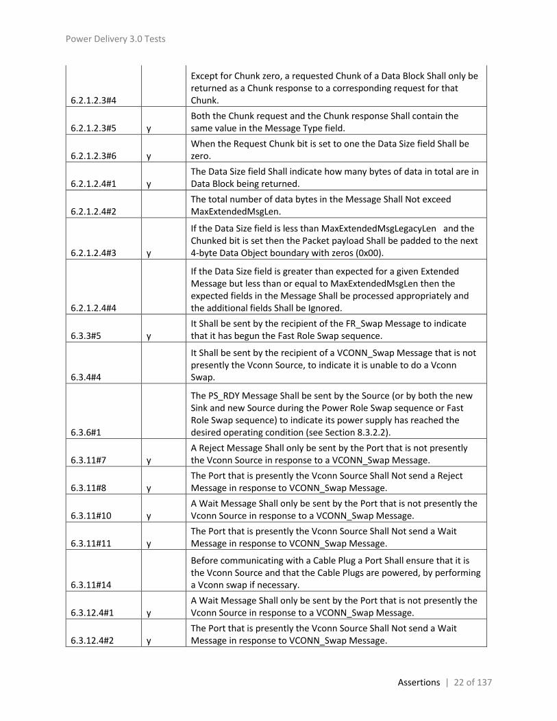
6.2.1.2.3#4
Except for Chunk zero, a requested Chunk of a Data Block Shall only be returned as a Chunk response to a corresponding request for that Chunk.
6.2.1.2.3#5 y Both the Chunk request and the Chunk response Shall contain the same value in the Message Type field.
6.2.1.2.3#6 y When the Request Chunk bit is set to one the Data Size field Shall be zero.
6.2.1.2.4#1 y The Data Size field Shall indicate how many bytes of data in total are in Data Block being returned.
6.2.1.2.4#2 The total number of data bytes in the Message Shall Not exceed MaxExtendedMsgLen.
6.2.1.2.4#3 y
If the Data Size field is less than MaxExtendedMsgLegacyLen and the Chunked bit is set then the Packet payload Shall be padded to the next 4-byte Data Object boundary with zeros (0x00).
6.2.1.2.4#4
If the Data Size field is greater than expected for a given Extended Message but less than or equal to MaxExtendedMsgLen then the expected fields in the Message Shall be processed appropriately and the additional fields Shall be Ignored.
6.3.3#5 y It Shall be sent by the recipient of the FR_Swap Message to indicate that it has begun the Fast Role Swap sequence.
6.3.4#4
It Shall be sent by the recipient of a VCONN_Swap Message that is not presently the Vconn Source, to indicate it is unable to do a Vconn Swap.
6.3.6#1
The PS_RDY Message Shall be sent by the Source (or by both the new Sink and new Source during the Power Role Swap sequence or Fast Role Swap sequence) to indicate its power supply has reached the desired operating condition (see Section 8.3.2.2).
6.3.11#7 y A Reject Message Shall only be sent by the Port that is not presently the Vconn Source in response to a VCONN_Swap Message.
6.3.11#8 y The Port that is presently the Vconn Source Shall Not send a Reject Message in response to VCONN_Swap Message.
6.3.11#10 y A Wait Message Shall only be sent by the Port that is not presently the Vconn Source in response to a VCONN_Swap Message.
6.3.11#11 y The Port that is presently the Vconn Source Shall Not send a Wait Message in response to VCONN_Swap Message.
6.3.11#14
Before communicating with a Cable Plug a Port Shall ensure that it is the Vconn Source and that the Cable Plugs are powered, by performing a Vconn swap if necessary.
6.3.12.4#1 y A Wait Message Shall only be sent by the Port that is not presently the Vconn Source in response to a VCONN_Swap Message.
6.3.12.4#2 y The Port that is presently the Vconn Source Shall Not send a Wait Message in response to VCONN_Swap Message.

Power Delivery 3.0 Tests
Assertions | 23 of 137
6.3.14#1 y The Not_Supported Message Shall be sent by a Port in response to any Message it does not support.
6.3.16#1 y The Source or Sink Shall respond by returning a Status Message (see Section 6.5.2).
6.3.17#1 y
The FR_Swap Message Shall be sent by the new Source within tFRSwapInit after it has detected a Fast Role Swap signal (see Section 5.8.6.3 and Section 6.6.16).
6.3.17#2 y The recipient of the FR_Swap Message Shall respond by sending an Accept Message.
6.3.17#3
After a successful Fast Role Swap the Port Partners Shall reset their respective Protocol Layers (equivalent to a Soft Reset): resetting their MessageIDCounter, RetryCounter and Protocol Layer state machines before attempting to establish an Explicit Contract.
6.3.17#4 At this point the Source Shall also reset its CapsCounter.
6.3.17#5
Since a UFP Source can attempt to send a Discover Identity Command using SOP’ to a Cable Plug prior to the establishment of an Explicit Contract, a DFP Sink Shall disable the receiving of SOP’ Messages until an Explicit Contract has been established.
6.3.17#6 Prior to the Fast Role Swap AMS the new Source Shall have Rd asserted on the CC wire and the new Sink Shall have Rp asserted on the CC wire.
6.3.17#7 y
During the Fast Role Swap AMS the new Source Shall change its CC Wire resistor from Rd to Rp and the new Sink Shall change its CC Wire resistor from Rp to Rd.
6.3.17#8 The DFP (Host), UFP (Device) roles and Vconn Source Shall remain unchanged during the Fast Role Swap process.
6.3.18#1 y The Port Shall respond by returning a PPS_Status Message (see Section 6.5.10).
6.3.19#1 y The Port Partner Shall respond by returning a Country_Codes Message (see Section 6.5.11).
6.4.1#3 y Power Data Objects in a Capabilities Message Shall be sent in the following order:
6.4.1#8 y The Programmable Power Supply Objects, if present, Shall be sent in Maximum Voltage order, lowest to highest.
6.4.1.2#6
Sinks with Accessory Support do not source VBUS (see [USB Type-C 1.2]) however when sourcing Vconn they Shall advertise vSafe5V with the Maximum Current set to 0mA in the first Power Data Object.

Power Delivery 3.0 Tests
Assertions | 24 of 137
6.4.1.2#9 y
A Sink that evaluates the Source_Capabilities Message it receives and identifies a PPS APDO Shall periodically re-request the PPS APDO at least every tPPSRequest until either: · The Sink requests something other than PPS APDO. · There is a Power Role Swap. · There is a Hard Reset
6.4.1.2#10 y
A Source that has accepted a Request Message with a Programmable RDO Shall issue Hard Reset Signaling if it has not received a Request Message with a Programmable RDO within tPPSTimeout.
6.4.1.2#11 y
The Source Shall discontinue this behavior after: · Receiving a Request Message with a Fixed, Variable or Battery RDO. · There is a Power Role Swap. · There is a Hard Reset.
6.4.1.2.2.6#1 y
The Unchunked Extended Messages Supported bit Shall be set when the Port can send and receive Extended Messages with Data Size > MaxExtendedMsgLegacyLen bytes in a single, Unchunked Message.
6.4.1.2.2.7#5 y
Supplies that support an extended overload capability specified in the PeakCurrent1…3 fields of the Source_Capabilities_Extended Message (see Section 6.5.1) Shall also set these bits to 00b.
6.4.1.2.2.7#6 y
Sinks wishing to utilize these extended capabilities Shall first send the Get_Source_Cap_Extended Message to determine what capabilities, if any are supported by the Source.
6.4.1.2.5#1 SPT The voltage fields define the output voltage range over which the power supply Shall be adjustable in 20mV steps.
6.4.1.2.5#2 SPT
The Maximum Current field contains the current the Programmable Power Supply Shall be capable of delivering over the advertised voltage range.
6.4.1.3.1.6#1 y The Fast Role Swap USB Type-C Current field Shall indicate the current level the Sink will require after a Fast Role Swap has been performed.
6.4.1.3.1.6#2 y
Initially when the new Source applies vSafe5V it will have Rd asserted but Shall provide the USB Type-C Current indicated by the new Sink in this field.
6.4.1.3.1.6#3 If the new Source is not able to supply this level of current it Shall Not perform a Fast Role Swap.
6.4.1.3.1.6#4
When Rp is asserted by the new Source during the Fast Role Swap AMS (see Section 6.3.17), the value of USB Type-C Current indicated by Rp Shall be the same or greater than that indicated in the Fast Role Swap USB Type-C Current field.
6.4.1.3.4#1 y The Maximum and Minimum Voltage fields Shall be set to the output voltage range that the Sink requires to operate.
6.4.1.3.4#2 y The Operational Current field Shall be set to the maximum current the Sink requires over the voltage range.

Power Delivery 3.0 Tests
Assertions | 25 of 137
6.4.2.6#1 y
The Unchunked Extended Messages Supported bit Shall be set when the Port can send and receive Extended Messages with Data Size > MaxExtendedMsgLegacyLen bytes in a single, Unchunked Message.
6.4.2.7#3 SPT When the request is accepted the Source’s output current supplied into any load Shall be less than or equal to the Operating Current.
6.4.2.7#4 SPT
When the Sink attempts to consume more current, the Source Shall reduce the output voltage so as not to exceed the Operating Current value.
6.4.2.7#6 Y This field Shall apply to the Fixed, Variable and Programmable RDO.
6.4.2.13#1 y
The Output Voltage field in the Programmable Request Data Object Shall be set by the Sink to the voltage the Sink requires as measured at the Source’s output connector.
6.4.2.13#2 y
The Output Voltage field Shall be greater than or equal to the Minimum Voltage field and less than or equal to the Maximum Voltage field in the Programmable Power Supply APDO.
6.4.2.13#3 y This field Shall apply to the Programmable RDO.
6.4.4.1#9 y When a DFP or UFP does not support Unstructured VDMs or does not recognize the VID it Shall return a Not_Supported Message.
6.4.4.2#6 y When a DFP or UFP does not support Structured VDMs any Structured VDMs received Shall return a Not_Supported Message.
6.4.4.2#10 y Version 1.0 = 00b (Shall Not be used)
6.4.4.2.3#2 y
To ensure interoperability with existing USBPD Products, USBPD Products Shall support every Structured VDM Version number starting from Version 1.0.
6.4.4.2.3#4 y
The Structured VDM Version field of the Discover Identity Command sent and received during VDM discovery Shall be used to determine the lowest common Structured VDM Version supported by the Port Partners or Cable Plug and Shall continue to operate using this Specification Revision until they are Detached.
6.4.4.3.1.1.3#1 y For DRD Products this field Shall indicate the capability regardless of the present Data Role.
6.4.4.3.1.1.6#1 y For DRD Products this field Shall indicate the capability regardless of the present Data Role.
6.4.4.3.1.1.6#2 y Table 6-32 defines the Product Type VDOs which Shall be returned.
6.4.4.3.1.1.6#3 y Shall be used where no other Product Type value is appropriate.
6.4.4.3.1.1.6#4 y Shall be used when the Product is a PDUSB Hub.
6.4.4.3.1.1.6#5 y Shall be used when the Product is a PDUSB Host.
6.4.4.3.1.1.6#6 y Shall be used when the Product is a Power Brick/Wall Wart.
6.4.4.3.1.1.6#7 Shall be used when the Product is a PDUSB Host or DFP that supports one or more Alternate Modes.

Power Delivery 3.0 Tests
Assertions | 26 of 137
6.4.4.3.1.4.1#3 y
Passive Cables Shall support the Structured VDM Discover Identity Command and Shall return the Passive Cable VDO in a Discover Identity Command ACK as shown in Table 6-35.
6.4.4.3.1.4.1#4 y 00b = Reserved, Shall Not be used
6.4.4.3.1.4.1#5 y 01b = Reserved, Shall Not be used
6.4.4.3.1.4.1#14 y
The Maximum VBUS Voltage field (B10…9) Shall contain the maximum voltage that Shall be negotiated using a Fixed Supply over the cable as part of an Explicit Contract where the maximum voltage that Shall be applied to the cable is vSrcNew max + vSrcValid max.
6.4.4.3.1.4.2#3 y
Active Cables Shall support the Structured VDM Discover Identity Command and Shall return the Active Cable VDO in a Discover Identity Command ACK as shown in Table 6-36.
6.4.4.3.1.4.2#4 y 00b = Reserved, Shall Not be used
6.4.4.3.1.4.2#5 y 01b = Reserved, Shall Not be used
6.4.4.3.1.4.2#14 y
The Maximum VBUS Voltage field (B10…9) Shall contain the maximum voltage that Shall be negotiated using a Fixed Supply over the cable as part of an Explicit Contract where the maximum voltage that Shall be applied to the cable is vSrcNew max + vSrcValid max.
6.4.5#1 y The Battery_Status Message Shall be sent in response to a Get_Battery_Status Message.
6.4.5#3 y The Battery_Status Message returns a BSDO whose format Shall be as shown in Figure 6-27 and Table 6-39.
6.4.5#4 y The Number of Data Objects field in the Battery_Status Message Shall be set to 1.
6.4.5#5 y When Battery is present Shall contain the Battery charging status:
6.4.5#6 y 11b: Reserved, Shall Not be used
6.4.5.2#1 y The Battery Info field Shall be used to report additional information about the Battery’s present status.
6.4.5.2#2 y The Battery Info field’s bits Shall reflect the present conditions under which the Battery is operating in the systems.
6.4.5.2.1#1 y
The Invalid Battery Reference bit Shall be set when the Get_Battery_Status Message contains a reference to a Battery that does not exist.
6.4.5.2.2#1 y The Battery is Present bit Shall be set whenever the Battery is present.
6.4.5.2.2#2 y It Shall always be set for Batteries that are not Hot Swappable Batteries.
6.4.5.2.3#1 y These bits Shall be set when the Battery is present bit is set.
6.4.5.2.3#2 y Otherwise when the Battery is present bit is zero the Battery charging status bits Shall also be zero.
6.4.6#1 The Alert Message Shall only be sent when the Source or Sink detects a status change.

Power Delivery 3.0 Tests
Assertions | 27 of 137
6.4.6#2 The Alert Message Shall contain exactly one Alert Data Object (ADO) and the format Shall be as shown in Figure 6-28 and Table 6-40.
6.4.6.1#1 The Type of Alert field Shall be used to report Source or Sink status changes.
6.4.6.1#2 Only one Alert Message Shall be generated for each Event or Change; however multiple Type of Alert bits May be set in one Alert Message.
6.4.6.1#3 Once the Alert Message has been sent the Type of Alert field Shall be cleared.
6.4.6.1.1#1 The Battery Status Change bit Shall be set when any Battery’s power state changes between charging, discharging, neither.
6.4.6.1.1#2 For Hot Swappable Batteries, it Shall also be set when a Battery is Attached or Detached.
6.4.6.1.2#1
The Over-Current Protection Event bit Shall be set when a Source detects its output current exceeds its limits triggering its protection circuitry.
6.4.6.1.3#1
The Over-Temperature Protection Event bit Shall be set when a Source or Sink shuts down due to over-temperature triggering its protection circuitry.
6.4.6.1.4#1
The Operating Condition Change bit Shall be set when a Source or Sink detects its Operating Condition enters or exits either the ‘warning’ or ‘over temperature’ temperature states.
6.4.6.1.4#2
The Operating Condition Change bit Shall be set when the Source operating in the Programmable Power Supply mode detects it has changed its operating condition between Constant Voltage (CV) and Current Foldback (CF).
6.4.6.1.5#1 The Source Input Event bit Shall be set when the Source/Sink’s input changes.
6.4.6.1.6#1
The Over-Voltage Protection Event bit Shall be set when the Sink detects its output voltage exceeds its limits triggering its protection circuitry.
6.4.6.2#1 Once the Alert Message has been sent the Fixed Batteries field Shall be cleared.
6.4.6.3#1 Once the Alert Message has been sent the Hot Swappable Batteries field Shall be cleared.
6.4.7#1
The Get_Country_Info Message Shall be sent by a port to get country specific information from its port partner using the country’s Alpha-2 Country Code defined by [ISO 3166].
6.4.7#2 The Get_Country_Info Message Shall be as shown in Figure 6-29 and Table 6-41.
6.5#1 y
An Extended Message Shall contain an Extended Message Header (indicated by the Extended field in the Message Header being set) and be followed by zero or more data bytes.

Power Delivery 3.0 Tests
Assertions | 28 of 137
6.5.1#1 y
The Source_Capabilities_Extended Message Shall return a 24-byte Source Capabilities Extended Data Block (SCEDB) whose format Shall be as shown in Figure 6-30 and Table 6-43.
6.5.1.1#1 The Vendor ID field Shall contain the 16-bit Vendor ID (VID) assigned to the Source’s vendor by the USB-IF.
6.5.1.1#2 If the vendor does not have a VID, the Vendor ID field Shall be set to zero.
6.5.1.1#3
Devices that have a USB data interface Shall report the same VID as the idVendor in the Standard Device Descriptor (see [USB 2.0] and [USB 3.1]).
6.5.1.2#1 The Product ID field Shall contain the 16-bit Product ID (PID) assigned by the Source’s vendor.
6.5.1.2#2
Devices that have a USB data interface Shall report the same PID as the idProduct in the Standard Device Descriptor (see [USB 2.0] and [USB 3.1]).
6.5.1.3#1 The XID field Shall contain the 32-bit XID provided by the USB-IF to the vendor who in turns assigns it to a product.
6.5.1.3#2 If the vendor does not have an XID, then it Shall return zero in this field (see [USB 2.0] and [USB 3.1]).
6.5.1.4#1 The Firmware Version field Shall contain an 8-bit firmware version number assigned to the device by the vendor.
6.5.1.5#1 The Hardware Version field Shall contain an 8-bit hardware version number assigned to the device by the vendor.
6.5.1.6.1#1 The Source Shall report its load step response capability in bits 0…1 of the Voltage Regulation bit field.
6.5.1.6.2#1 The Source Shall report its load step magnitude rate as a percentage of IoC in bit 2 of the Voltage Regulation field.
6.5.1.7#1 The Holdup Time field Shall contain the Source’s holdup time (see Section 7.1.12.2).
6.5.1.8#1 The Compliance field Shall contain the standards the Source is compliant with (see Section 7.1.12.3).
6.5.1.9#1
A Source Shall set the Touch Current bit (bit-0) when their leakage current is less than 65µA rms when Source’s maximum capability is less than or equal to 30W, or when their leakage current is less than 100 µA rms when its power capability is between 30W and 100W.
6.5.1.9#2 The total combined leakage current Shall be measured in accordance with [IEC 60950-1] when tested at 250VAC rms at 50 Hz.
6.5.1.9#3 A Source with a ground pin Shall set the Ground pin bit (bit-1).
6.5.1.9#4 A Source whose Ground pin is intended to be connected to a protective earth Shall set both bit1 and bit 2.
6.5.1.10#1 The Peak Current field Shall contain the combinations of Peak Current that the Source supports (see Section 7.1.12.4).

Power Delivery 3.0 Tests
Assertions | 29 of 137
6.5.1.10#2 A Source Shall populate unused Peak Current bit fields with zero.
6.5.1.10#3
Percentage Overload Shall be the maximum peak current reported in 10% increments as a percentage of the negotiated operating current (IoC) offered by the Source.
6.5.1.10#4 Overload Period Shall be the minimum rolling average time window in 20ms increments, where a value of 20ms is recommended.
6.5.1.10#5 Duty Cycle Shall be the maximum percentage of overload period reported in 5% increments.
6.5.1.10#6 VBUS Droop Shall be set to one to indicate there is an additional 5% voltage droop on VBUS when the overload conditions occur.
6.5.1.11#1 The Touch Temp field Shall report the IEC standard used to determine the surface temperature of the Source’s enclosure.
6.5.1.12#1 The Source Inputs field Shall identify the possible inputs that provide power to the Source.
6.5.1.13#1 The Batteries field Shall report the number of batteries the source supports.
6.5.1.13#2 y It Shall independently report the number of Hot Swappable Batteries and the number of Fixed batteries.
6.5.1.13#3 y The maximum number of each type of Battery Shall be no more than 4.
6.5.1.14#1 y The Source PDP field Shall report the Source’s rated PDP as defined in Table 10-2.
6.5.2#1 y The Status Message Shall be sent in response to a Get_Status Message.
6.5.2#2 y The Status Message returns a 5-byte Status Data Block (SDB) whose format Shall be as shown in Figure 6-31 and Table 6-44.
6.5.2#4 y
When Present Source Input field bit 3 is not set this field is Reserved and shall be set to zero.
6.5.2.4#1
The OTP, OVP and OCP event flags Shall be set when there is an event and Shall only be cleared when read with the Get_PPS_Status Message.
6.5.2.4#2 y When the OTP event flag is set the Temperature Status field Shall also be set to over temperature.
6.5.2.4#3 The CF/CV mode bit is only Valid when operating as a Programmable Power Supply and Shall be Ignored otherwise.
6.5.2.4#4 SPT
When the Source is operating as a Programmable Power Supply the CF/CV mode bit Shall be set when operating in Current Foldback mode (CF mode) and Shall be cleared when operating in Constant Voltage mode (CV mode).
6.5.2.5#1 y When the Temperature Status field is set to over temperature the OTP event flag Shall also be set.

Power Delivery 3.0 Tests
Assertions | 30 of 137
6.5.3#1 y
The Port Shall respond by returning a Battery_Capabilities Message (see Section 6.5.5) containing a Battery Capabilities Data Block (BCDB) for the targeted Battery.
6.5.3#2
The Get_Battery_Cap Message contains a 1 byte Get Battery Cap Data Block (GBCDB), whose format Shall be as shown in Figure 6-32 and Table 6-45.
6.5.3#3 The Data Size field in the Get_Battery_Cap Message Shall be set to 1.
6.5.4#2 y
The Get_Battery_Status Message contains a 1 byte Get Battery Status Data Block (GBSDB) whose format Shall be as shown in Figure 6-33 and Table 6-46.
6.5.4#3 y The Data Size field in the Get_Battery_Status Message Shall be set to 1.
6.5.5#2 y The Battery_Capabilities Message returns a 9-byte BCDB whose format Shall be as shown in Figure 6-34 and Table 6-44.
6.5.5.1#1 The Battery Design Capacity field Shall return the Battery’s design capacity in tenths of WH.
6.5.5.3.1#1 y
The Invalid Battery Reference bit Shall be set when the Get_Battery_Cap Message contains a reference to a Battery that does not exist.
6.5.6#1 y
The Port or Cable Plug Shall respond by returning a Manufacturer_Info Message (Section 6.5.7) containing a Manufacturer Info Data Block (MIDB).
6.5.6#2 The Get_Manufacturer_Info Message returns a GMIDB whose format Shall be as shown in Figure 6-33 and Table 6-48.
6.5.6#3
If Manufacturer Info Target subfield is Battery (01b) the Manufacturer Info Ref field Shall contain the Battery number reference which is the number of the Battery indexed from zero:
6.5.6#4 Otherwise this field is Reserved and Shall be set to zero.
6.5.7#1 y The Manufacturer_Info Message Shall be sent in response to a Get_Manufacturer_Info Message.
6.5.7#2 y
The Manufacturer_Info Message returns a Manufacturer Info Data Block (MIDB) whose format Shall be as shown in Figure 6-34 and Table 6-44.
6.5.7.1#1 y This field Shall contain the device’s or Battery’s16-bit vendor ID assigned by the USB.
6.5.7.2#1 y This field Shall contain the device’s or Battery’s 16-bit product identifier designated by the vendor.
6.5.7.3#1 This field Shall contain the device’s or Battery’s manufacturer string as defined by the vendor.

Power Delivery 3.0 Tests
Assertions | 31 of 137
6.5.7.3#2 y
If the Manufacturer Info Target field or Manufacturer Info Ref field in the Get_Manufacturer_Info Message is unrecognized the field Shall return zero bytes.
6.5.8.1#1 The Security_Request Message contains a Security Request Data Block (SRQDB) whose format Shall be as shown in Figure 6-37.
6.5.8.2#1 The Security_Response Message contains a Security Response Data Block (SRPDB) whose format Shall be as shown in Figure 6-38.
6.5.9.1#1
The Firmware_Update_Request Message contains a Firmware Update Request Data Block (FRQDB) whose format Shall be as shown in Figure 6-39.
6.5.9.2#1
The Firmware_Update_Response Message contains a Firmware Update Response Data Block (FRPDB) whose format Shall be as shown in Figure 6-40.
6.5.10#1 y The PPS_Status Message Shall be sent in response to a Get_PPS_Status Message.
6.5.10#3 y
The PPS_Status Message Shall return a 4-byte PPS Status Data Block (PPSSDB) whose format Shall be as shown in Figure 6-41 and Table 6-50.
6.5.10.1#1 y The Output Voltage field Shall return the Source’s output voltage at the time of the request.
6.5.10.1#2 y If the Source does not support this field, it Shall be set to 0xFFFF.
6.5.10.2#1 y The Output Current field Shall return the Source’s output current at the time of the request.
6.5.10.2#2 y If the Source does not support this field, it Shall be set to 0xFF.
6.5.10.3#1 y The PTF (Present Temperature Flag) Shall provide a real time indication of the Source’s internal thermal status.
6.5.10.3#2 y The OMF (Operating Mode Flag) Shall provide a real time indication of the Source’s operating mode.
6.5.11#1 y The Country_Codes Message Shall be sent in response to a Get_Country_Codes Message.
6.5.11#2 y
The Country_Codes Message Shall contain a 4-260 byte Country Code Data Block (CCDB) whose format Shall be as shown in Figure 6-42 and Table 6-51.
6.5.11.1#1 y The Country Code field Shall contain the Alpha-2 Country Code defined by [ISO 3166].
6.5.12#1 y The Country_Info Message Shall be sent in response to a Get_Country_Info Message.
6.5.12#2 y
The Country_Info Message Shall contain a 4-260 byte Country Info Data Block (CIDB) whose format Shall be as shown in Figure 6-43 and Table 6-52.
6.5.12.1#1 y The Country Code field Shall contain the Alpha-2 Country Code defined by [ISO 3166].

Power Delivery 3.0 Tests
Assertions | 32 of 137
6.5.12.2#1
The Country Specific Data field Shall contain content defined by and formatted in a manner determined by an official agency of the country indicated in the Country Code field.
6.6.3.3#1 y
After Port Partners are Attached or after a Hard Reset or after a Power Role Swap or after a Fast Role Swap a Source Shall send its first Source_Capabilities Message within tFirstSourceCap of VBUS reaching vSafe5V.
6.6.5.2.2#1 y When the FR_Swap Message request has been sent by the initial Sink, the initial Source Shall respond with an Accept Message.
6.6.5.2.2#2
When the last bit of the EOP of the GoodCRC Message corresponding to this Accept Message is received by the initial Sink, then the PSSourceOffTimer Shall be started.
6.6.5.2.2#3 y The PSSourceOffTimer Shall be stopped when:
6.6.5.2.2#4 y
The timer Shall time out if a PS_RDY Message has not been received from the initial Source within tPSSourceOff indicating this has occurred.
6.6.5.3.2#1 y The PSSourceOnTimer Shall be started when:
6.6.5.3.2#2 y The PSSourceOnTimer Shall be stopped when:
6.6.16#1 y
That last bit of the EOP of the FR_Swap Message Shall be transmitted by the new Source no later than tFRSwapInit after the Fast Role Swap request has been detected (see Section 5.8.6.3).
6.6.17.1#1 y The ChunkingNotSupportedTimer Shall be started when:
6.6.17.1#2 y The Policy Engine Shall Not send its Not_Supported Message before the ChunkingNotSupportedTimer expires.
6.6.17.2#1
The ChunkSenderRequestTimer Shall be used by the sender’s Chunking state machine to ensure that a Chunk Response is responded to within a bounded time of tChunkSenderRequest.
6.6.17.2#2 The ChunkSenderRequestTimer Shall be started when:
6.6.17.2#3 The ChunkSenderRequestTimer Shall be stopped when:
6.6.17.2#4
The receiver of a Chunk Response requiring a Chunk Request Shall respond with a Chunk Request within tChunkReceiverRequest in order to ensure that the sender’s ChunkSenderRequestTimer does not expire.
6.6.17.2#5
The tChunkReceiverRequest time Shall be measured from the time the last bit of the Message EOP has been received by the Physical Layer until the first bit of the response Message Preamble has been transmitted by the Physical Layer.
6.6.17.3#1 y
The ChunkSenderResponseTimer Shall be used by the sender’s Chunking state machine to ensure that a Chunk Request is responded to within a bounded time of tChunkSenderResponse.
6.6.17.3#2 y The ChunkSenderResponseTimer Shall be started when:
6.6.17.3#3 The ChunkSenderResponseTimer Shall be stopped when:

Power Delivery 3.0 Tests
Assertions | 33 of 137
6.6.17.3#4
The receiver of a Chunk Request requiring a Chunk Response Shall respond with a Chunk Response within tChunkReceiverResponse in order to ensure that the sender’s ChunkSenderResponseTimer does not expire.
6.6.17.3#5 y
The tChunkReceiverResponse time Shall be measured from the time the last bit of the Message EOP has been received by the Physical Layer until the first bit of the response Message Preamble has been transmitted by the Physical Layer.
6.6.18.1#1 y
The SinkPPSPeriodicTimer Shall be used by the Sink’s Policy Engine to ensure that a Request Message requesting a PPS APDO is sent periodically within a bounded time of tPPSRequest.
6.6.18.1#2 y
The tPPSRequest time Shall be measured from the time the last bit of the EOP of the GoodCRC Message sent by the Source in response to the previous Request Message.
6.6.18.1#3 y
SinkPPSPeriodicTimer Shall be re-initialized and restarted when the last bit of the EOP of the GoodCRC Message sent in response to a Request Message for a PPS APDO has been received by the Physical Layer.
6.6.18.1#4
The Sink Shall stop the SinkPPSPeriodicTimer when: · The Sink requests something other than PPS APDO. · There is a Power Role Swap. · There is a Hard Reset.
6.6.18.2#1 y
The SourcePPSCommTimer Shall be used by the Source’s Policy Engine to ensure that a Request Message requesting a PPS APDO is received periodically within a bounded time of tPPSTimeout.
6.6.18.2#2 y
The tPPSTimeout time Shall be measured from the time the last bit of the EOP of the GoodCRC Message sent in response to the previous Request Message for a PPS APDO has been sent by the Physical Layer.
6.6.18.2#3 y
The SourcePPSCommTimer Shall be re-initialized and restarted when the last bit of the EOP of the GoodCRC Message sent in response to a Request Message for a PPS APDO has been sent by the Physical Layer.
6.6.18.2#4 y
The Source Shall stop the SourcePPSCommTimer when: · A Request Message has been received. · There is a Power Role Swap. · There is a Hard Reset.
6.6.18.2#5 y When the SourcePPSCommTimer times out the Source Shall issue Hard Reset Signaling.
6.7.2#3 Extended Messages of Data Size > MaxExtendedMsgLegacyLen that are not Chunked (Chunked flag set to zero) Shall Not be retried .
6.7.2#4 Extended Messages of Data Size ≤ MaxExtendedMsgLegacyLen (Chunked flag set to zero or one) Shall be retried.

Power Delivery 3.0 Tests
Assertions | 34 of 137
6.7.2#5
Extended Messages of Data Size > MaxExtendedMsgLegacyLen that are Chunked (Chunked flag set to one) individual Chunks Shall be retried.
6.8.1#4 y
If the incoming Message is an Unexpected Message received in the PE_SNK_Ready or PE_SRC_Ready state the Policy Engine Shall issue a Soft Reset.
6.8.1#6 y
An unrecognized or unsupported Message received in the PE_SNK_Ready or PE_SRC_Ready states, Shall Not cause a Soft_Reset Message to be generated but instead a Not_Supported Message Shall be generated.
6.8.1#7 y A Soft_Reset Message Shall be sent regardless of the Rp value either SinkTxOk or SinkTxNG if it is the correct response in that state,
6.8.2#6 y A Sink Shall be able to send Hard Reset signaling regardless of the value of Rp (see Section 5.7).
6.11.2#2 When Chunking is supported there Shall be separate Chunked Tx, Chunked Tx and Chunked Message Router State Machine instances.
6.11.2.1.1#1 y
In this case it Shall implement the ChunkingNotSupportedTimer to ensure compatible operation with partners which support Chunking (see Section 6.6.17.1 and Section 8.3.3.5).
6.11.2.1.1.2#1 The message Shall be considered aborted when the Abort Flag is again cleared by the Chunked Tx state machine.
6.11.2.1.2.1#1 The Chunked Rx State Machine Shall enter the RCH_Wait_For_Message_From_Protocol_Layer state:
6.11.2.1.2.1#2 The Chunked Rx State Machine Shall transition to the RCH_Pass_Up_Message state when:
6.11.2.1.2.1#3 y The Chunked Rx State Machine Shall transition to the RCH_Processing_Extended_Message state when:
6.11.2.1.2.2#1 y On entry to the RCH_Pass_Up_Message state the Chunked Rx state machine Shall pass the received message to the Policy Engine.
6.11.2.1.2.2#2 The Chunked Rx State Machine Shall transition to the RCH_Wait_For_Message_From_Protocol_Layer state when:
6.11.2.1.2.3#1 On entry to the RCH_Processing_Extended_Message state the Chunked Rx state machine Shall:
6.11.2.1.2.3#2 y The Chunked Rx State Machine Shall transition to the RCH_Pass_Up_Message state when:
6.11.2.1.2.3#3 y The Chunked Rx State Machine Shall transition to the RCH_Requesting_Chunk state when:
6.11.2.1.2.3#4 The Chunked Rx State Machine Shall transition to the RCH_Report_Error state when:
6.11.2.1.2.3#5 The Chunked Rx State Machine Shall transition to the RCH_Wait_For_Message_From_Protocol_Layer state when:

Power Delivery 3.0 Tests
Assertions | 35 of 137
6.11.2.1.2.4#1 y On entry to the RCH_Requesting_Chunk state the Chunked Rx state machine Shall:
6.11.2.1.2.4#2 y The Chunked Rx State Machine Shall transition to the RCH_Waiting_Chunk state when:
6.11.2.1.2.4#3 The Chunked Rx State Machine Shall transition to the RCH_Report_Error state when:
6.11.2.1.2.5#1 y
On entry to the RCH_Waiting_Chunk state the Chunked Rx state machine Shall: Start the ChunkSenderResponseTimer.
6.11.2.1.2.5#2 y The Chunked Rx State Machine Shall transition to the RCH_Processing_Extended_Message state when:
6.11.2.1.2.5#3 y
The Chunked Rx State Machine Shall transition to the RCH_Report_Error state when: A Message, other than a Chunk, is received from the Protocol Layer, or · The ChunkSenderResponseTimer expires
6.11.2.1.2.6#1 The Chunked Rx State Machine Shall enter the RCH_Report_Error state:
6.11.2.1.2.6#2 On entry to the RCH_Report_Error state the Chunked Rx state machine Shall:
6.11.2.1.2.6#3 If the state was entered because a Message was received, this Message Shall be passed to the Policy Engine.
6.11.2.1.2.6#4 y
The Chunked Rx State Machine Shall transition to the RCH_Wait_For_Message_From_Protocol_Layer state when: The error has been reported. · Any message received was passed to the Policy Engine.
6.11.2.1.3.1#1 The Chunked Tx State Machine Shall enter the TCH_Wait_For_Message_Request_From_Policy_Engine state:
6.11.2.1.3.1#2 The Chunked Tx State Machine Shall transition to the TCH_Pass_Down_Message state when:
6.11.2.1.3.1#3 The Chunked Tx State Machine Shall transition to the TCH_Prepare_To_Send_Chunked_Message state when:
6.11.2.1.3.1#4
The Chunked Tx State Machine Shall Discard the Message Request and remain in the TCH_Wait_For_Message_Request_From_Policy_Engine state when:
6.11.2.1.3.1#5 The Chunked Tx State Machine Shall Discard the Message Request and enter the TCH_Report_Error state when:
6.11.2.1.3.2#1 On entry to the TCH_Pass_Down_Message state the Chunked Tx State Machine Shall pass the message to the Protocol Layer.
6.11.2.1.3.2#2 The Chunked Tx State Machine Shall transition to the TCH_Wait_For_Transmision_Complete state when:

Power Delivery 3.0 Tests
Assertions | 36 of 137
6.11.2.1.3.3#1 The Chunked Tx State Machine Shall transition to the TCH_Message_Sent state when:
6.11.2.1.3.3#2 The Chunked Tx State Machine Shall transition to the TCH_Report_Error state when:
6.11.2.1.3.4#1 On entry to the TCH_Message_Sent state the Chunked Tx State Machine Shall:
6.11.2.1.3.4#2 The Chunked Tx State Machine Shall transition to the TCH_Wait_For_Message_Request_From_Policy_Engine state when:
6.11.2.1.3.5#1 On entry to the TCH_Prepare_To_Send_Chunked_Message state the Chunked Tx State Machine Shall:
6.11.2.1.3.5#2 The Chunked Tx State Machine Shall transition to the TCH_Construct_Chunked_Message state when:
6.11.2.1.3.6#1 On entry to the TCH_Construct_Chunked_Message state the Chunked Tx State Machine Shall:
6.11.2.1.3.6#2 The Chunked Tx State Machine Shall transition to the TCH_Sending_Chunked_Message state when:
6.11.2.1.3.6#3 The Chunked Tx State Machine Shall transition to the TCH_Wait_For_Message_Request_From_Policy_Engine state when:
6.11.2.1.3.7#1 The Chunked Tx State Machine Shall transition to the TCH_Wait_Chunk_Request state when:
6.11.2.1.3.7#2 The Chunked Tx State Machine Shall transition to the TCH_Message_Sent state when:
6.11.2.1.3.7#3 The Chunked Tx State Machine Shall transition to the TCH_Report_Error state when:
6.11.2.1.3.8#1 On entry to the TCH_Wait_Chunk_Request state the Chunked Tx State Machine Shall:
6.11.2.1.3.8#2 The Chunked Tx State Machine Shall transition to the TCH_Report_Error state when:
6.11.2.1.3.8#3 The Chunked Tx State Machine Shall transition to the TCH_Message_Sent state when:
6.11.2.1.3.8#4 The Chunked Tx State Machine Shall transition to the TCH_Message_Received state when:
6.11.2.1.3.9#1 The Chunked Tx State Machine Shall enter the TCH_Message_Received state:
6.11.2.1.3.9#2 On entry to the TCH_Message_Received state the Chunked Tx State Machine Shall:
6.11.2.1.3.9#3 The Chunked Tx State Machine Shall transition to the TCH_Wait_For_Message_Request_From_Policy_Engine state when:
6.11.2.1.3.10#1 On entry to the TCH_Report_Error state the Chunked Tx State Machine Shall:
6.11.2.1.3.10#2 The Chunked Tx State Machine Shall transition to the TCH_Wait_For_Message_Request_From_Policy_Engine state when:

Power Delivery 3.0 Tests
Assertions | 37 of 137
6.11.2.1.4.1#1 The Chunked Message Router Shall transition to the RTR_Rx_Chunks state when:
6.11.2.1.4.1#2 The Chunked Message Router Shall transition to the RTR_Tx_Chunks state when:
6.11.2.1.4.1#3 The Chunked Message Router Shall transition to the RTR_Ping state when:
6.11.2.1.4.2#1 On entry to the RTR_Rx_Chunks state the Chunked Message Router Shall:
6.11.2.1.4.3#1 On entry to the RTR_Ping state the Chunked Message Router Shall:
6.11.2.1.4.4#1 On entry to the RTR_Tx_Chunks state the Chunked Message Router Shall:
6.11.2.2.2.1#1 y
The Protocol Layer in a Source Shall transition from the PRL_Tx_Wait_for_Message_Request state to the PRL_Tx_Src_Sink_Tx state when:
6.11.2.2.2.1#2 y On entry to the PRL_Tx_Src_Sink_Tx state the Protocol Layer Shall request the PHY Layer to Rp to SinkTxOk.
6.11.2.2.2.1#3 The Protocol Layer Shall transition to the PRL_Tx_Wait_for_Message_Request state when:
6.11.2.2.2.2#1
The Protocol Layer in a Source Shall transition from the PRL_Tx_Wait_for_Message_Request state to the PRL_Tx_Src_Source_Tx state when:
6.11.2.2.2.2#2 On entry to the PRL_Tx_Src_Source_Tx state the Protocol Layer Shall set Rp to SinkTxNG.
6.11.2.2.2.2#3 The Protocol Layer Shall transition to the PRL_Tx_Src_Pending state when:
6.11.2.2.2.3#1 On entry to the PRL_Tx_Src_Pending state the SinkTxTimer Shall be initialized and run.
6.11.2.2.2.3#2 The Protocol Layer Shall transition to the PRL_Tx_Construct_Message state when:
6.11.2.2.2.3#3 The Protocol Layer Shall transition to the PRL_Tx_Layer_Reset_for_Transmit state when:
6.11.2.2.3.1#1 y
The Protocol Layer in a Sink Shall transition from the PRL_Tx_Wait_for_Message_Request state to the PRL_Tx_Snk_Start_of_AMS state when:
6.11.2.2.3.1#2 y The Protocol Layer Shall transition to the PRL_Tx_Snk_Pending state when:
6.11.2.2.3.2#1 y The Protocol Layer Shall transition to the PRL_Tx_Construct_Message state when:
6.11.2.2.3.2#2 The Protocol Layer Shall transition to the PRL_Tx_Layer_Reset_for_Transmit state when:
6.12.1#6 y Note 5: Shall be supported products that support the Source_Capabilities_Extended Message.

Power Delivery 3.0 Tests
Assertions | 38 of 137
6.12.1#8 y Note 7: Shall be supported when the Fast Role Swap signal is supported.
6.12.1#10 y Note 9: Shall be supported when PPS is supported.
6.12.2#4 y Note 2: Shall be supported by products that contain batteries.
6.12.2#5 Note 3: Shall be supported by products that support the Get_Battery_Status Message.
6.12.3#3 y Note 1: Shall be supported by products that contain batteries.
6.12.3#8 Note 6: Shall be supported by products that support USB security communication as defined in [USBTypeCAuthentication 1.0]
6.12.3#9 Note 7: Shall be supported by products that support USB firmware update communication as defined in [USBPDFirmwareUpdate 1.0]
6.12.3#10 y Note 8: Shall be supported when PPS is supported.
6.12.4#2 y If Structured VDMs are not supported, the DFP or UFP receiving a VDM Command Shall send a Not_Supported Message in response.
6.12.6#1 Table 6-65 details the Fast Role Swap signal that Shall/Should/ Shall Not be transmitted and received by a Source or Sink.
7.1.3#5 SPT
The output voltage of the Programmable Power Supply Shall remain within a range defined by the relative tolerance vPpsNew and the absolute band vPpsValid.
7.1.4.3#2 SPT
The Output Voltage value in the Programmable RDO defines the nominal value of the PPS output voltage after completing a voltage change and Shall settle within the limits defined by vPpsNew by tPpsSrcTransition.
7.1.4.3#3 SPT Any undershoot or overshoot beyond vPpsNew Shall Not exceed vPpsValid at any time.
7.1.4.3#4 SPT
The PPS output voltage May change in a step-wise or linear manner and the slew rate of either type of change Shall Not exceed vPpsSlewPos for voltage increases or vPpsSlewNeg for voltage decreases.
7.1.4.3#5 The nominal requested voltage of all linear voltage changes Shall equate to an integer number of LSB changes.
7.1.4.3#6 SPT A PPS Shall be able to supply the negotiated current level as it change its output voltage to the requested level.
7.1.4.3#7 SPT All PPS voltage increases Shall result in a voltage that is greater than the previous PPS output voltage.
7.1.4.3#8 SPT Likewise, all PPS voltage decreases Shall result in a voltage that is less than the previous PPS output voltage.
7.1.4.3#9 If the Sink negotiates for a new PPS APDO, then the transition between the two PPS APDOs Shall occur as described in Section 7.3.18.

Power Delivery 3.0 Tests
Assertions | 39 of 137
7.1.4.4#1 SPT
The Programmable Power Supply Shall foldback its output current to the Operating Current value in the Programmable RDO when the Sink attempts to draw more current than the Output Current level.
7.1.4.4#2 SPT All programming changes of the Operating Current Shall settle to the new Operating Current value within tPpsCfProgramSettle.
7.1.4.4#3 SPT A Source that supports PPS Shall support foldback programmability between iPpsCfMin and the Maximum Current value in the PPS APDO.
7.1.4.4#4 SPT
Any current overshoot or undershoot that occurs due to a load change during Current Foldback Shall Not exceed iPpsCfTransient and Shall settle to the Operating Current value within tPpsCfSettle.
7.1.4.4#5 SPT
Voltage overshoot or undershoot caused by a transition from Current Foldback mode to Constant Voltage mode Shall Not exceed vPpsCfCvTransient and Shall settle to the Operating Voltage value within tPpsCfCvTransient.
7.1.4.4#6 SPT
Likewise, current overshoot or undershoot caused by a transition from Constant Voltage mode to Current Foldback mode Shall Not exceed iPpsCvCfTransient and Shall settle to the Operating Current value within tPpsCvCfTransient.
7.1.4.4#7 SPT
The PPS Shall maintain its output voltage within the Minimum Voltage and Maximum Voltage values advertised in the PPS APDO for all static and dynamic load conditions during Current Foldback operation.
7.1.4.4#8 SPT Rather, the Source Shall send Hard Reset Signaling and discharge VBUS to vSafe0V then resume default operation at vSafe5V.
7.1.8.1#1 SPT after tPpsSrcTransition) and during static load conditions the Source output voltage Shall remain within the vPpsNew limits.
7.1.8.1#2 SPT
after tPpsSrcTransition) and during transient load conditions the Source output voltage Shall Not go beyond the range specified by vPpsValid.
7.1.8.1#3 SPT The amount of time the Source output voltage can be in the band between vPpsNew and vPpsValid Shall Not exceed tPpsTransient.
7.1.12.1.1#1 A Source Shall meet the following requirements under the load step reported in the Extended Source Capabilities:
7.1.12.1.1#2 The Source Shall maintain VBUS regulation within the vSrcValid range.
7.1.12.1.1#3 The noise on the CC line Shall remain below vNoiseIdle and vNoiseActive.
7.1.12.1.1#4
The Source Shall ensure that PD Communications meet the transmit and receive masks as specified in Section 5.8.2 under all load conditions.
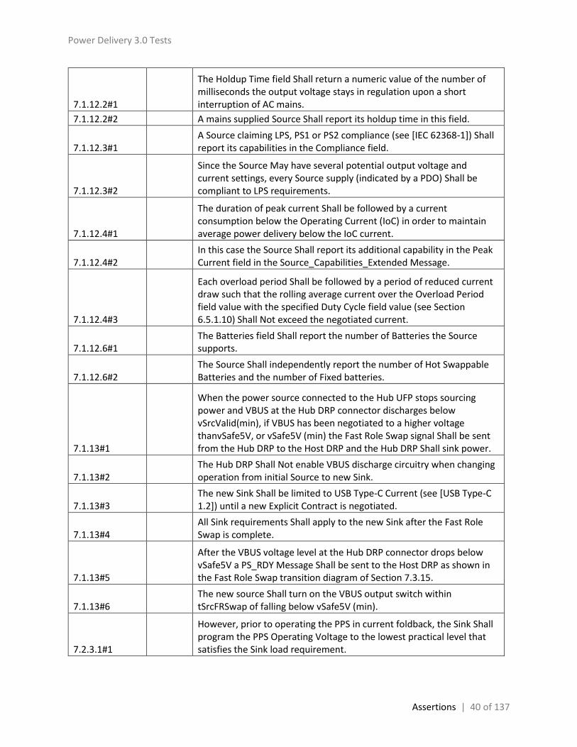
Power Delivery 3.0 Tests
Assertions | 40 of 137
7.1.12.2#1
The Holdup Time field Shall return a numeric value of the number of milliseconds the output voltage stays in regulation upon a short interruption of AC mains.
7.1.12.2#2 A mains supplied Source Shall report its holdup time in this field.
7.1.12.3#1 A Source claiming LPS, PS1 or PS2 compliance (see [IEC 62368-1]) Shall report its capabilities in the Compliance field.
7.1.12.3#2
Since the Source May have several potential output voltage and current settings, every Source supply (indicated by a PDO) Shall be compliant to LPS requirements.
7.1.12.4#1
The duration of peak current Shall be followed by a current consumption below the Operating Current (IoC) in order to maintain average power delivery below the IoC current.
7.1.12.4#2 In this case the Source Shall report its additional capability in the Peak Current field in the Source_Capabilities_Extended Message.
7.1.12.4#3
Each overload period Shall be followed by a period of reduced current draw such that the rolling average current over the Overload Period field value with the specified Duty Cycle field value (see Section 6.5.1.10) Shall Not exceed the negotiated current.
7.1.12.6#1 The Batteries field Shall report the number of Batteries the Source supports.
7.1.12.6#2 The Source Shall independently report the number of Hot Swappable Batteries and the number of Fixed batteries.
7.1.13#1
When the power source connected to the Hub UFP stops sourcing power and VBUS at the Hub DRP connector discharges below vSrcValid(min), if VBUS has been negotiated to a higher voltage thanvSafe5V, or vSafe5V (min) the Fast Role Swap signal Shall be sent from the Hub DRP to the Host DRP and the Hub DRP Shall sink power.
7.1.13#2 The Hub DRP Shall Not enable VBUS discharge circuitry when changing operation from initial Source to new Sink.
7.1.13#3 The new Sink Shall be limited to USB Type-C Current (see [USB Type-C 1.2]) until a new Explicit Contract is negotiated.
7.1.13#4 All Sink requirements Shall apply to the new Sink after the Fast Role Swap is complete.
7.1.13#5
After the VBUS voltage level at the Hub DRP connector drops below vSafe5V a PS_RDY Message Shall be sent to the Host DRP as shown in the Fast Role Swap transition diagram of Section 7.3.15.
7.1.13#6 The new source Shall turn on the VBUS output switch within tSrcFRSwap of falling below vSafe5V (min).
7.2.3.1#1
However, prior to operating the PPS in current foldback, the Sink Shall program the PPS Operating Voltage to the lowest practical level that satisfies the Sink load requirement.

Power Delivery 3.0 Tests
Assertions | 41 of 137
7.2.3.1#2
When operating with a PPS that is in current foldback, the Sink Shall Not change its load in a manner that exceeds iPpsCfLoadStepRate or iPpsCfLoadReleaseRate.
7.2.3.1#3 The load change magnitude Shall Not exceed iPpsCfLoadStep or iPpsCfLoadRelease.
7.2.3.1#4
If the Sink negotiates for a new PPS APDO, then the Sink Shall transition to Sink Standby while changing between PPS APDOs as described in Section 7.3.18.
7.2.6#3
The Sink’s operating current Shall Not change faster than the value reported in the Source’s Load Step Slew Rate field and Shall ensure that PD Communications meet the transmit and receive masks as specified in Section 5.8.2.
7.2.9.4#2 The Sink Shall never draw higher current than the Maximum Current value in the PPS APDO.
7.2.10#1
When the Host DRP that supports Fast Role Swap detects the Fast Role Swap signal, the Host DRP Shall stop sinking current and Shall be ready and able to source vSafe5V if the residual VBUS voltage level at the Host DRP connector is greater than vSafe5V.
7.2.10#2
When the residual VBUS voltage level at the Host DRP connector discharges below vSafe5V(min) the Host DRP as the new Source Shall supply vSafe5V to the Hub DRP within tSrcFRSwap.
7.2.10#3 The Host DRP Shall Not enable VBUS discharge circuitry when changing roles from initial Sink to new Source.
7.2.10#4
The new Source Shall supply vSafe5V at USB Type-C Current (see [USB Type-C 1.2]) at the value advertised in the Fast Role Swap USB Type-C Current field (see Section 6.4.1.3.1.6).
7.2.10#5
All Source requirements Shall apply to the new Source after the Fast Role Swap is complete The Fast Role Swap response of the Hub DRP is described in Section 7.1.13 since the Hub DRP is operating as the initial Source prior to the Fast Role Swap.
7.2.10#6
After the Host DRP is providing VBUS power to the Hub DRP, a PS_RDY Message Shall be sent to the Hub DRP as defined by the Fast Role Swap signaling and messaging sequence detailed in Section 7.3.15.
7.3.15#1 The interaction of the System Policy, Device Policy, and power supply that Shall be followed during a Fast Role Swap is shown in Figure 7-29.
7.3.15#2 The sequence that Shall be followed is described in Table 7-15.
7.3.15#3 The timing parameters that Shall be followed are listed in Table 7-19 and Table 7-20.
7.3.15#4 The Policy Engine Shall wait for Step D1 before sending the PS_RDY Message.

Power Delivery 3.0 Tests
Assertions | 42 of 137
7.3.15#5
The Policy Engine Shall wait for Step E before sending the PS_RDY Message.
7.3.16#4 SPT The Programmable Power Supply new voltage Shall be reached by tPpsSrcTransition.
7.3.17#4 SPT The Programmable Power Supply new voltage Shall be reached by tPpsSrcTransition.
7.3.18#1 SPT The Source voltage as the transition starts Shall be any voltage within the Valid VBUS range of the previous Source PDO or APDO.
7.3.18#2 SPT The Source voltage after the transition is complete Shall be any voltage within the Valid VBUS range of the new Source PDO or APDO.
7.3.18#5 SPT The Source transition to the new PDO or APDO VBUS voltage Shall be completed by tSrcTransition.
7.4.1#2 SPT The time the Programmable Power Supply Shall transition between requested voltages.
8.3.3.2.6#6 y
On entry to the PE_SNK_Ready state if the current Explicit Contract is for a PPS APDO, then the Policy Engine Shall do the following: · Initialize and run the SourcePPSCommTimer
8.3.3.2.6#7
On exit from the PE_SRC_Ready, if the Source is initiating an AMS then the Policy Engine Shall notify the Protocol Layer that the first Message in an AMS will follow.
8.3.3.3.7#4 y
On entry to the PE_SNK_Ready state if the current Explicit Contract is for a PPS APDO, then the Policy Engine Shall do the following: · Initialize and run the SinkPPSPeriodicTimer.
8.3.3.5.1.1#1 y
The PE_SRC_Send_Not_Supported state Shall be entered from the PE_SRC_Ready state either as the result of a Protocol Error received during an interruptible AMS or as a result of an unsupported Message being received in the PE_SRC_Ready state directly except for the first Chunk in a multi-Chunk Message (see also Section 6.11.2.1 and Section 8.3.3.4.1).
8.3.3.5.1.1#2 y
On entry to the PE_SRC_Send_Not_Supported state (from the PE_SRC_Ready state) the Policy Engine Shall request the Protocol Layer to send a Not_Supported Message.
8.3.3.5.1.3#1 y
The PE_SRC_Chunk_Received state Shall be entered from the PE_SRC_Ready state either as the result of a Protocol Error received during an interruptible AMS or as a result of an unsupported Message being received in the PE_SRC_Ready state directly where the Message is a Chunk in a multi-Chunk Message (see also Section 6.6.17.1 and Section 8.3.3.4.1).
8.3.3.5.1.3#2 y
On entry to the PE_SRC_Chunk_Received state (from the PE_SRC_Ready state) the Policy Engine Shall initialize and run the ChunkingNotSupportedTimer.

Power Delivery 3.0 Tests
Assertions | 43 of 137
8.3.3.5.1.3#3 y The Policy Engine Shall transition to PE_SRC_Send_Not_Supported when:
8.3.3.5.2.1#1 y
The PE_SNK_Send_Not_Supported state Shall be entered from the PE_SNK_Ready state either as the result of a Protocol Error received during an interruptible AMS or as a result of an unsupported Message being received in the PE_SNK_Ready state directly except for the first Chunk in a multi-Chunk Message (see also Section 6.11.2.1 and Section 8.3.3.4.1).
8.3.3.5.2.1#2 y
On entry to the PE_SNK_Send_Not_Supported state (from the PE_SNK_Ready state) the Policy Engine Shall request the Protocol Layer to send a Not_Supported Message.
8.3.3.5.2.3#1 y
The PE_SNK_Chunk_Received state Shall be entered from the PE_SNK_Ready state either as the result of a Protocol Error received during an interruptible AMS or as a result of an unsupported Message being received in the PE_SNK_Ready state directly where the Message is a Chunk in a multi-Chunk Message (see also Section 6.6.17.1 and Section 8.3.3.4.1).
8.3.3.5.2.3#2 y
On entry to the PE_SNK_Chunk_Received state (from the PE_SNK_Ready state) the Policy Engine Shall initialize and run the ChunkingNotSupportedTimer.
8.3.3.5.2.3#3 y The Policy Engine Shall transition to PE_SNK_Send_Not_Supported when:
8.3.3.7.1.1#1
The PE_SRC_Send_Source_Alert state Shall be entered from the PE_SRC_Ready state when the Device Policy Manager indicates that there is a Source alert condition to be reported.
8.3.3.7.1.1#2 On entry to the PE_SRC_Send_Source_Alert state the Policy Engine Shall request the Protocol Layer to send an Alert Message.
8.3.3.7.1.1#3 The Policy Engine Shall transition back to PE_SRC_Ready (see Figure 8-66) when:
8.3.3.7.2.1#1 y The PE_SNK_Source_Alert_Received state Shall be entered from the PE_SNK_Ready state when an Alert Message is received.
8.3.3.7.2.1#2 y
On entry to the PE_SNK_Source_Alert_Received state the Policy Engine Shall inform the Device Policy Manager of the details of the Source alert.
8.3.3.7.2.1#3 y The Policy Engine Shall transition back to PE_SNK_Ready (see Figure 8-67) when:
8.3.3.7.3.1#1
The PE_SNK_Send_Sink_Alert state Shall be entered from the PE_SNK_Ready state when the Device Policy Manager indicates that there is a Source alert condition to be reported.
8.3.3.7.3.1#2 On entry to the PE_SNK_Send_Sink_Alert state the Policy Engine Shall request the Protocol Layer to send an Alert Message.

Power Delivery 3.0 Tests
Assertions | 44 of 137
8.3.3.7.3.1#3 The Policy Engine Shall transition back to PE_SNK_Ready (see Figure 8-67) when:
8.3.3.7.4.1#1 y The PE_SRC_Sink_Alert_Received state Shall be entered from the PE_SRC_Ready state when an Alert Message is received.
8.3.3.7.4.1#2 y
On entry to the PE_SRC_Sink_Alert_Received state the Policy Engine Shall inform the Device Policy Manager of the details of the Source alert.
8.3.3.7.4.1#3 y The Policy Engine Shall transition back to PE_SRC_Ready (see Figure 8-66) when:
8.3.3.8.1.1#1
The Policy Engine Shall transition to the PE_SNK_Get_Source_Cap_Ext state, from the PE_SNK_Ready state, due to a request to get the remote extended source capabilities from the Device Policy Manager.
8.3.3.8.1.1#2
On entry to the PE_SNK_Get_Source_Cap_Ext state the Policy Engine Shall send a Get_Source_Cap_Extended Message and initialize and run the SenderResponseTimer.
8.3.3.8.1.1#3
On exit from the PE_SNK_Get_Source_Cap_Ext state the Policy Engine Shall inform the Device Policy Manager of the outcome (capabilities or response timeout).
8.3.3.8.1.1#4 The Policy Engine Shall transition back to the PE_SNK_Ready state (see Figure 8-67) when:
8.3.3.8.2.1#1 y
The Policy Engine Shall transition to the PE_SRC_Give_Source_Cap_Ext state, from the PE_SRC_Ready state, when a Get_Source_Cap_Extended Message is received.
8.3.3.8.2.1#2 y
On entry to the PE_SRC_Give_Source_Cap_Ext state the Policy Engine Shall request the present extended Source capabilities from the Device Policy Manager and then send a Source_Capabilities_Extended Message based on these capabilities.
8.3.3.8.2.1#3 The Policy Engine Shall transition back to the PE_SRC_Ready state (see Figure 8-66) when:
8.3.3.9.1.1#1 y
The Policy Engine Shall transition to the PE_SNK_Get_Source_Status state, from the PE_SNK_Ready state, due to a request to get the remote source status from the Device Policy Manager.
8.3.3.9.1.1#2 y
On entry to the PE_SNK_Get_Source_Status state the Policy Engine Shall send a Get_Status Message and initialize and run the SenderResponseTimer.
8.3.3.9.1.1#3
On exit from the PE_SNK_Get_Source_Status state the Policy Engine Shall inform the Device Policy Manager of the outcome (status or response timeout).
8.3.3.9.1.1#4 The Policy Engine Shall transition back to the PE_SNK_Ready state (see Figure 8-67) when:

Power Delivery 3.0 Tests
Assertions | 45 of 137
8.3.3.9.2.1#1 y
The Policy Engine Shall transition to the PE_SRC_Give_Source_Status state, from the PE_SRC_Ready state, when a Get_Status Message is received.
8.3.3.9.2.1#2 y
On entry to the PE_SRC_Give_Source_Status state the Policy Engine Shall request the present Source status from the Device Policy Manager and then send a Status Message based on these capabilities.
8.3.3.9.3.1#1 y
The Policy Engine Shall transition to the PE_SRC_Get_Sink_Status state, from the PE_SRC_Ready state, due to a request to get the remote source status from the Device Policy Manager.
8.3.3.9.3.1#2 y
On entry to the PE_SRC_Get_Sink_Status state the Policy Engine Shall send a Status Message and initialize and run the SenderResponseTimer.
8.3.3.9.3.1#3
On exit from the PE_SRC_Get_Sink_Status state the Policy Engine Shall inform the Device Policy Manager of the outcome (status or response timeout).
8.3.3.9.3.1#4 The Policy Engine Shall transition back to the PE_SRC_Ready state (see Figure 8-66) when:
8.3.3.9.4.1#1 y
The Policy Engine Shall transition to the PE_SNK_Give_Sink_Status state, from the PE_SNK_Ready state, when a Get_Status Message is received.
8.3.3.9.4.1#2 y
On entry to the PE_SNK_Give_Sink_Status state the Policy Engine Shall request the present extended Source capabilities from the Device Policy Manager and then send a Status Message based on these capabilities.
8.3.3.9.5.1#1
The Policy Engine Shall transition to the PE_SNK_Get_PPS_Status state, from the PE_SNK_Ready state, due to a request to get the remote source PPS status from the Device Policy Manager.
8.3.3.9.5.1#2
On entry to the PE_SNK_Get_PPS_Status state the Policy Engine Shall send a Get_PPS_Status Message and initialize and run the SenderResponseTimer.
8.3.3.9.5.1#3
On exit from the PE_SNK_Get_PPS_Status state the Policy Engine Shall inform the Device Policy Manager of the outcome (status or response timeout).
8.3.3.9.5.1#4 The Policy Engine Shall transition back to the PE_SNK_Ready state (see Figure 8-67) when:
8.3.3.9.6.1#1 y
The Policy Engine Shall transition to the PE_SRC_Give_PPS_Status state, from the PE_SRC_Ready state, when a Get_PPS_Status Message is received.
8.3.3.9.6.1#2 y
On entry to the PE_SRC_Give_PPS_Status state the Policy Engine Shall request the present Source PPS status from the Device Policy Manager and then send a PPS_Status Message based on these capabilities.

Power Delivery 3.0 Tests
Assertions | 46 of 137
8.3.3.9.6.1#3 The Policy Engine Shall transition back to the PE_SRC_Ready state (see Figure 8-66) when:
8.3.3.10.1.1#1
The Policy Engine Shall transition to the PE_Get_Battery_Cap state, from either the PE_SRC_Ready or PE_SNK_Ready state, due to a request to get the remote Battery capabilities, for a specified Battery, from the Device Policy Manager.
8.3.3.10.1.1#2
On entry to the PE_Get_Battery_Cap state the Policy Engine Shall send a Get_Battery_Cap Message and initialize and run the SenderResponseTimer.
8.3.3.10.1.1#3
On exit from the PE_Get_Battery_Cap state the Policy Engine Shall inform the Device Policy Manager of the outcome (capabilities or response timeout).
8.3.3.10.1.1#4
The Policy Engine Shall transition back to either the PE_SRC_Ready or PE_SNK_Ready state as appropriate (see Figure 8-66 and Figure 8-67) when:
8.3.3.10.2.1#1 y
The Policy Engine Shall transition to the PE_Give_Battery_Cap state, from either the PE_SRC_Ready or PE_SNK_Ready state, when a Get_Battery_Cap Message is received.
8.3.3.10.2.1#2 y
On entry to the PE_Give_Battery_Cap state the Policy Engine Shall request the present Battery capabilities, for the requested Battery, from the Device Policy Manager and then send a Source_Capabilities_Extended Message based on these capabilities.
8.3.3.11.1.1#1 y
The Policy Engine Shall transition to the PE_Get_Battery_Status state, from either the PE_SRC_Ready or PE_SNK_Ready state, due to a request to get the remote Battery status, for a specified Battery, from the Device Policy Manager.
8.3.3.11.1.1#2 y
On entry to the PE_Get_Battery_Status state the Policy Engine Shall send a Get_Battery_Status Message and initialize and run the SenderResponseTimer.
8.3.3.11.1.1#3
On exit from the PE_Get_Battery_Status state the Policy Engine Shall inform the Device Policy Manager of the outcome (status or response timeout).
8.3.3.11.1.1#4
The Policy Engine Shall transition back to either the PE_SRC_Ready or PE_SNK_Ready state as appropriate (see Figure 8-66 and Figure 8-67) when:
8.3.3.11.2.1#1 y
The Policy Engine Shall transition to the PE_Give_Battery_Status state, from either the PE_SRC_Ready or PE_SNK_Ready state, when a Get_Battery_Status Message is received.
8.3.3.11.2.1#2 y
On entry to the PE_Give_Battery_Status state the Policy Engine Shall request the present Battery status, for the requested Battery, from the Device Policy Manager and then send a Battery_Status Message based on this status.

Power Delivery 3.0 Tests
Assertions | 47 of 137
8.3.3.12.1.1#1
The Policy Engine Shall transition to the PE_Get_Manufacturer_Info state, from either the PE_SRC_Ready or PE_SNK_Ready state, due to a request to get the remote Manufacturer Information from the Device Policy Manager.
8.3.3.12.1.1#2
On entry to the PE_Get_Manufacturer_Info state the Policy Engine Shall send a Get_Manufacturer_Info Message and initialize and run the SenderResponseTimer.
8.3.3.12.1.1#3
On exit from the PE_Get_Manufacturer_Info state the Policy Engine Shall inform the Device Policy Manager of the outcome (status or response timeout).
8.3.3.12.1.1#4
The Policy Engine Shall transition back to either the PE_SRC_Ready or PE_SNK_Ready state as appropriate (see Figure 8-66 and Figure 8-67) when:
8.3.3.12.2.1#1 y
The Policy Engine Shall transition to the PE_Give_Manufacturer_Info state, from either the PE_SRC_Ready, PE_SNK_Ready or PE_CBL_Ready state, when a Get_Manufacturer_Info Message is received.
8.3.3.12.2.1#2 y
On entry to the PE_Give_Manufacturer_Info state the Policy Engine Shall request the manufacturer information from the Device Policy Manager and then send a Manufacturer_Info Message based on this status.
8.3.3.13.1.1#1
The Policy Engine Shall transition to the PE_Get_Country_Codes state, from either the PE_SRC_Ready or PE_SNK_Ready state, due to a request to get the remote Manufacturer Information from the Device Policy Manager.
8.3.3.13.1.1#2
On entry to the PE_Get_Country_Codes state the Policy Engine Shall send a Get_Country_Codes Message and initialize and run the SenderResponseTimer.
8.3.3.13.1.1#3
On exit from the PE_Get_Country_Codes state the Policy Engine Shall inform the Device Policy Manager of the outcome (status or response timeout).
8.3.3.13.1.1#4
The Policy Engine Shall transition back to either the PE_SRC_Ready or PE_SNK_Ready state as appropriate (see Figure 8-66 and Figure 8-67) when:
8.3.3.13.2.1#1 y
The Policy Engine Shall transition to the PE_Give_Country_Codes state, from either the PE_SRC_Ready, PE_SNK_Ready or PE_CBL_Ready state, when a Get_Country_Codes Message is received.
8.3.3.13.2.1#2 y
On entry to the PE_Give_Country_Codes state the Policy Engine Shall request the country codes from the Device Policy Manager and then send a Country_Codes Message containing these codes.

Power Delivery 3.0 Tests
Assertions | 48 of 137
8.3.3.13.2.1#3
The Policy Engine Shall transition back to either the PE_SRC_Ready, PE_SNK_Ready or PE_CBL_Ready state as appropriate (see Figure 8-66, Figure 8-67and Figure 8-126) when:
8.3.3.13.3.1#1
The Policy Engine Shall transition to the PE_Get_Country_Info state, from either the PE_SRC_Ready or PE_SNK_Ready state, due to a request to get the remote Manufacturer Information from the Device Policy Manager.
8.3.3.13.3.1#2
On entry to the PE_Get_Country_Info state the Policy Engine Shall send a Get_Manufacturer_Info Message and initialize and run the SenderResponseTimer.
8.3.3.13.3.1#3
On exit from the PE_Get_Country_Info state the Policy Engine Shall inform the Device Policy Manager of the outcome (country information or response timeout).
8.3.3.13.3.1#4
The Policy Engine Shall transition back to either the PE_SRC_Ready or PE_SNK_Ready state as appropriate (see Figure 8-66 and Figure 8-67) when:
8.3.3.13.4.1#1 y
The Policy Engine Shall transition to the PE_Give_Country_Info state, from either the PE_SRC_Ready, PE_SNK_Ready or PE_CBL_Ready state, when a Get_Country_Info Message is received.
8.3.3.13.4.1#2 y
On entry to the PE_Give_Country_Info state the Policy Engine Shall request the country information from the Device Policy Manager and then send a Country_Info Message containing this country information.
8.3.3.13.4.1#3
The Policy Engine Shall transition back to either the PE_SRC_Ready, PE_SNK_Ready or PE_CBL_Ready state as appropriate (see Figure 8-66, Figure 8-67and Figure 8-126) when:
8.3.3.14.2.1#1 y
The Policy Engine Shall transition to the PE_Send_Security_Response state, from either the PE_SRC_Ready, PE_SNK_Ready or PE_CBL_Ready state, when a Security_Request Message is received.
8.3.3.14.2.1#2 y
On entry to the PE_Send_Security_Response state the Policy Engine Shall request the appropriate response from the Device Policy Manager and then send a Security_Response Message based on this status.
8.3.3.14.2.1#3
The Policy Engine Shall transition back to either the PE_SRC_Ready, PE_SNK_Ready or PE_CBL_Ready state as appropriate (see Figure 8-66, Figure 8-67and Figure 8-126) when:
8.3.3.15.1.1#1
The Policy Engine Shall transition to the PE_Send_Firmware_Update_Request state, from either the PE_SRC_Ready or PE_SNK_Ready state, due to a request to send a firmware update request from the Device Policy Manager.
8.3.3.15.1.1#2 On entry to the PE_Send_Firmware_Update_Request state the Policy Engine Shall send a Firmware_Update_Request Message.

Power Delivery 3.0 Tests
Assertions | 49 of 137
8.3.3.15.1.1#3
The Policy Engine Shall transition back to either the PE_SRC_Ready or PE_SNK_Ready state as appropriate (see Figure 8-66 and Figure 8-67) when:
8.3.3.15.2.1#1
The Policy Engine Shall transition to the PE_Send_Firmware_Update_Response state, from either the PE_SRC_Ready, PE_SNK_Ready or PE_CBL_Ready state, when a Firmware_Update_Request Message is received.
8.3.3.15.2.1#2
On entry to the PE_Send_Firmware_Update_Response state the Policy Engine Shall request the appropriate response from the Device Policy Manager and then send a Firmware_Update_Response Message based on this status.
8.3.3.15.2.1#3
The Policy Engine Shall transition back to either the PE_SRC_Ready, PE_SNK_Ready or PE_CBL_Ready state as appropriate (see Figure 8-66, Figure 8-67and Figure 8-126) when:
8.3.3.15.3.1#1
The Policy Engine Shall transition to the PE_Firmware_Update_Response_Received state, from either the PE_SRC_Ready or PE_SNK_Ready when a Firmware_Update_Response Message is received.
8.3.3.15.3.1#2
On entry to the PE_Firmware_Update_Response_Received state the Policy Engine Shall inform the Device Policy Manager of the details of the firmware update response.
8.3.3.15.3.1#3
The Policy Engine Shall transition back to either the PE_SRC_Ready or PE_SNK_Ready state as appropriate (see Figure 8-66, Figure 8-67 and Figure 8-126) when:
8.3.3.16.5#2
In addition they Should have the capability to do a Fast Role Swap from the PE_SRC_Ready state and Shall return to USB Default Operation on a Hard Reset.
8.3.3.16.5#3
Figure 8-103 shows the additional state diagram required to perform a Fast Role Swap from Source to Sink roles and the changes that Shall be followed for error handling.
8.3.3.16.5.1#1 The Fast Role Swap process Shall start only from the PE_SRC_Ready state where power is stable.
8.3.3.16.5.1#2 The Policy Engine Shall transition to the PE_FRS_SRC_SNK_Evaluate_Swap state when:
8.3.3.16.5.2#1
The Policy Engine Shall transition to the PE_FRS_SRC_SNK_CC_Signal state from any other state provided there is an Explicit Contract in place when:
8.3.3.16.5.2#2 The Policy Engine Shall transition to the PE_FRS_SRC_SNK_Evaluate_Swap state when:
8.3.3.16.5.3#1
On entry to the PE_FRS_SRC_SNK_Evaluate_Swap state the Policy Engine Shall ask the Device Policy Manager whether a Fast Role Swap can be made.

Power Delivery 3.0 Tests
Assertions | 50 of 137
8.3.3.16.5.3#2 The Policy Engine Shall transition to the PE_FRS_SRC_SNK_Accept_Swap state when:
8.3.3.16.5.3#3 y The Policy Engine Shall transition to the PE_SRC_Hard_Reset state when:
8.3.3.16.5.4#1 On entry to the PE_FRS_SRC_SNK_Accept_Swap state the Policy Engine Shall request the Protocol Layer to send an Accept Message.
8.3.3.16.5.4#2 The Policy Engine Shall transition to the PE_FRS_SNK_SRC_Transition_to_off state when:
8.3.3.16.5.4#3 y The Policy Engine Shall transition to the PE_SRC_Hard_Reset state when:
8.3.3.16.5.4#4 Note: a soft reset Shall Not be initiated in this case.
8.3.3.16.5.5#1 y On entry to the PE_FRS_SNK_SRC_Transition_to_off state the Policy Engine Shall until VBUS has discharged to vSafe5V.
8.3.3.16.5.5#2 The Policy Engine Shall transition to the PE_PRS_SRC_SNK_Assert_Rd state when:
8.3.3.16.5.6#1
On entry to the PE_PRS_SRC_SNK_Assert_Rd state the Policy Engine Shall request the Device Policy Manager to change the resistor asserted on the CC wire from Rp to Rd.
8.3.3.16.5.6#2 The Policy Engine Shall transition to the PE_PRS_SRC_SNK_Wait_Source_on state when:
8.3.3.16.5.7#1 y
On entry to the PE_PRS_SRC_SNK_Wait_Source_on state the Policy Engine Shall request the Protocol Layer to send a PS_RDY Message and Shall start the PSSourceOnTimer.
8.3.3.16.5.7#2 y On exit from the Source off state the Policy Engine Shall stop the PSSourceOnTimer.
8.3.3.16.5.7#3 The Policy Engine Shall transition to the PE_SNK_Startup when:
8.3.3.16.5.7#4 y The Policy Engine Shall transition to the ErrorRecovery state when:
8.3.3.16.5.7#5 Note: a soft reset Shall Not be initiated in this case.
8.3.3.16.6#1 Dual-Role Ports that combine Sink and Source capabilities Shall comprise Sink and Source Policy Engine state machines.
8.3.3.16.6#2
In addition they Should have the capability to do a Fast Role Swap from the PE_SNK_Ready state and Shall return to USB Default Operation on a Hard Reset.
8.3.3.16.6#3
Figure 8-104 shows the additional state diagram required to perform a Fast Role Swap from Sink to Source roles and the changes that Shall be followed for error handling.
8.3.3.16.6.1#1
The Policy Engine Shall transition to the PE_FRS_SNK_SRC_Send_Swap state from any other state provided there is an Explicit Contract in place when:
8.3.3.16.6.1#2
On entry to the PE_FRS_SNK_SRC_Start_AMS state the Policy Engine Shall notify the Protocol Layer that the first Message in an AMS will follow.

Power Delivery 3.0 Tests
Assertions | 51 of 137
8.3.3.16.6.1#3 The Policy Engine Shall transition to the PE_FRS_SNK_SRC_Send_Swap state when:
8.3.3.16.6.2#1
On entry to the PE_FRS_SNK_SRC_Send_Swap state the Policy Engine Shall request the Protocol Layer to send an FR_Swap Message and Shall initialize and run the SenderResponseTimer.
8.3.3.16.6.2#2 The Policy Engine Shall transition to the PE_FRS_SNK_SRC_Transition_to_off state when:
8.3.3.16.6.2#3 y
The Policy Engine Shall transition to the ErrorRecovery state when: The SenderResponseTimer times out or The FR_Swap Message is not sent after retries (a GoodCRC Message has not been received). A soft reset Shall Not be initiated in this case.
8.3.3.16.6.2#4 A soft reset Shall Not be initiated in this case.
8.3.3.16.6.3#1
On entry to the PE_FRS_SNK_SRC_Transition_to_off state the Policy Engine Shall initialize and run the PSSourceOffTimer and then request the Device Policy Manager to turn off the Sink.
8.3.3.16.6.3#2 y The Policy Engine Shall transition to the ErrorRecovery state when:
8.3.3.16.6.3#3 The Policy Engine Shall transition to the PE_FRS_SNK_SRC_Vbus_Applied state when:
8.3.3.16.6.4#1 The Policy Engine Shall transition to the PE_FRS_SNK_SRC_Assert_Rp state when:
8.3.3.16.6.5#1
On entry to the PE_FRS_SNK_SRC_Assert_Rp state the Policy Engine Shall request the Device Policy Manager to change the resistor asserted on the CC wire from Rd to Rp.
8.3.3.16.6.5#2 The Policy Engine Shall transition to the PE_FRS_SNK_SRC_Source_on state when:
8.3.3.16.6.6#1 On entry to the PE_FRS_SNK_SRC_Source_on state the Policy Engine Shall request the Device Policy Manager to turn on the Source.
8.3.3.16.6.6#2
On exit from the PE_FRS_SNK_SRC_Source_on state (except if the exit is to send a Ping Message) the Policy Engine Shall send a PS_RDY Message.
8.3.3.16.6.6#3 The Policy Engine Shall transition to the PE_SRC_Startup state when:
8.3.3.16.6.6#4 y The Policy Engine Shall transition to the ErrorRecovery state when:
8.3.3.16.6.6#5 A soft reset Shall Not be initiated in this case.
8.3.3.16.11.1#1
The Policy Engine Shall transition to the PE_DR_SRC_Get_Source_Cap_Ext state, from the PE_SRC_Ready state, due to a request to get the remote extended source capabilities from the Device Policy Manager.
8.3.3.16.11.1#2
On entry to the PE_DR_SRC_Get_Source_Cap_Ext state the Policy Engine Shall send a Get_Source_Cap_Extended Message and initialize and run the SenderResponseTimer.

Power Delivery 3.0 Tests
Assertions | 52 of 137
8.3.3.16.11.1#3
On exit from the PE_DR_SRC_Get_Source_Cap_Ext state the Policy Engine Shall inform the Device Policy Manager of the outcome (capabilities or response timeout).
8.3.3.16.11.1#4 The Policy Engine Shall transition back to the PE_SRC_Ready state (see Figure 8-66) when:
8.3.3.16.12.1#1 y
The Policy Engine Shall transition to the PE_DR_SNK_Give_Source_Cap_Ext state, from the PE_SNK_Ready state, when a Get_Source_Cap_Extended Message is received.
8.3.3.16.12.1#2 y
On entry to the PE_DR_SNK_Give_Source_Cap_Ext state the Policy Engine Shall request the present extended Source capabilities from the Device Policy Manager and then send a Source_Capabilities_Extended Message based on these capabilities.
8.3.3.23.1.1#2
On entry to the PE_BIST_Carrier_Mode state the Policy Engine Shall tell the Protocol Layer to go to BIST Carrier Mode and Shall initialize and run the BISTContModeTimer.
8.3.3.23.1.1#3
The Policy Engine Shall transition to either the PE_SRC_Transition_to_default state, PE_SNK_Transition_to_default state or PE_CBL_Ready state (as appropriate) when:
10.2.3.2#1 y The Programmable Power Supply’s PDP Shall be calculated as the product of the Nominal Voltage times the Maximum Current.
10.2.3.2#3 y A Source that advertises Optional Programmable Power Supply APDOs Shall advertise the PDOs and APDOs shown in Table 10-7.
10.2.3.2#4 y
A Source Shall advertise Optional Programmable Power Supply APDOs with Maximum Voltage and Minimum Voltages for nominal voltage as defined in Table 10-8.
10.2.3.2#5 y
A Source that advertises Programmable Power Supply APDOs other than the ones listed in Table 10-8 Shall Not advertise additional APDO's with a Maximum Voltage * Maximum Current that exceeds the adapter's PDP.
10.2.3.2#6 y In no case Shall a Source advertise a current that exceeds the attached cable’s current rating.
10.2.3.2#7 y Table 10-7 shows the Programmable Power Supply APDOs that Shall be offered for a given PDP.
10.2.3.2.1#1 The voltage output at the Source’s connector Shall be +/-5% for both the Maximum Voltage and the Minimum Voltage.
Common assertions to all tests
6.2.1.1.8#1,

Power Delivery 3.0 Tests
Tests Applicability | 53 of 137
Tests Applicability Test Consumer Only Comsumer/Provider Provider Only Provider/Consumer Dual-role Port Cable
TD.PD.LL3.E1 Y Y Y Y Y
TD.PD.LL3.E2 Y Y Y Y Y
TD.PD.LL3.E3 Y Y Y Y Y Y
TD.PD.SRC3.E1 Y Y Y
TD.PD.SRC3.E2 Y Y Y
TD.PD.SRC3.E3 Y Y Y
TD.PD.SRC3.E4 Y Y Y
TD.PD.SRC3.E5 Y Y Y
TD.PD.SRC3.E6 Y Y Y
TD.PD.SRC3.E7 Y Y Y
TD.PD.SRC3.E8 Y Y Y
TD.PD.SRC3.E9 Y Y Y
TD.PD.SRC3.E10 Y Y Y
TD.PD.SRC3.E11 Y Y Y
TD.PD.SRC3.E12 Y Y Y
TD.PD.SRC3.E13 Y Y Y
TD.PD.SRC3.E14 Y Y Y
TD.PD.SRC3.E15 Y Y Y
TD.PD.SRC3.E16 Y Y Y
TD.PD.SRC3.E17 Y Y Y
TD.PD.SRC3.E18 Y Y Y
TD.PD.SRC3.E19 Y Y Y
TD.PD.SRC3.E20 Y Y Y
TD.PD.SRC3.E21 Y Y Y
TD.PD.SRC3.E22 Y Y Y
TD.PD.SRC3.E23 Y Y Y
TD.PD.SRC3.E24 Y Y Y
TD.PD.SRC3.E25 Y Y Y
TD.PD.SRC3.E26 Y Y Y
TD.PD.SRC3.E27 Y Y Y
TD.PD.SRC3.E28 Y Y Y
TD.PD.SRC3.E29 Y Y Y
TD.PD.SRC3.E30 Y Y Y
TD.PD.SRC3.E31 Y Y Y
TD.PD.SRC3.E32 Y Y Y
TD.PD.SRC3.E33 Y Y Y
TD.PD.SRC3.E34 Y Y Y
TD.PD.SRC3.E35 Y Y Y
TD.PD.SRC3.E36 Y Y Y
TD.PD.SNK3.E1 Y Y Y
TD.PD.SNK3.E2 Y Y Y
TD.PD.SNK3.E3 Y Y Y
TD.PD.SNK3.E4 Y Y Y
TD.PD.SNK3.E5 Y Y Y
TD.PD.SNK3.E6 Y Y Y
TD.PD.SNK3.E7 Y Y Y
TD.PD.SNK3.E8 Y Y Y
TD.PD.SNK3.E9 Y Y Y
TD.PD.SNK3.E10 Y Y Y
TD.PD.SNK3.E11 Y Y Y
TD.PD.SNK3.E12 Y Y Y
TD.PD.SNK3.E13 Y Y Y
TD.PD.SNK3.E14 Y Y Y
TD.PD.SNK3.E15 Y Y Y
TD.PD.SNK3.E16 Y Y Y
TD.PD.SNK3.E17 Y Y Y
TD.PD.SNK3.E18 Y Y Y
TD.PD.SNK3.E19 Y Y Y
TD.PD.SNK3.E20 Y Y Y
TD.PD.CBL3.E1 Y

Power Delivery 3.0 Tests
Tests Applicability | 54 of 137
Test Consumer Only Comsumer/Provider Provider Only Provider/Consumer Dual-role Port Cable
TD.PD.CBL3.E2 Y
TD.PD.CBL3.E3 Y
TD.PD.CBL3.E4 Y
TD.PD.CBL3.E5 Y
TD.PD.CBL3.E6 Y
TD.PD.CBL3.E7 Y
TD.PD.CBL3.E8 Y
TD.PD.VDM3.E1 Y Y Y Y Y Y
TD.PD.VDM3.E2 Y Y Y
TD.PD.FRSISRC3.E1 Y Y
TD.PD.FRSISRC3.E2 Y Y
TD.PD.FRSISRC3.E3 Y Y
TD.PD.FRSISRC3.E4 Y Y
TD.PD.FRSISRC3.E5 Y Y
TD.PD.FRSISRC3.E6 Y Y
TD.PD.FRSISNK3.E1 Y Y
TD.PD.FRSISNK3.E2 Y Y
TD.PD.FRSISNK3.E3 Y Y
TD.PD.FRSISNK3.E4 Y Y
TD.PD.FRSISNK3.E5 Y Y
TD.PD.FRSISNK3.E6 Y Y
TD.PD.VNDI3.E1 Y Y Y
TD.PD.VNDI3.E2 Y Y Y
TD.PD.VNDI3.E3 Y Y Y Y Y Y
TD.PD.VNDI3.E4 Y Y Y Y Y Y
TD.PD.VNDI3.E5 Y Y Y Y Y Y
TD.PD.VNDI3.E6 Y Y Y Y Y
TD.PD.VNDI3.E7 Y Y Y Y Y Y
TD.PD.VNDI3.E8 Y Y Y Y
TD.PD.VNDI3.E9 Y Y Y

Power Delivery 3.0 Tests
Link Layer Tests | 55 of 137
Link Layer Tests
TD.PD.LL3.E1. GoodCRC Specification Revision compatibility
Applicable to:
- UUT: Provider Only, Provider / Consumer, Dual-role Port, Consumer Only, Consumer / Provider
Assertions Tested:
6.2.1.1.5#4
Description:
The Tester verifies the UUT accepts GoodCRC with Specification Revision set to 00b, 01b, or 10b.
Steps:
a) The Tester is configured to reply GoodCRC with Specification Revision set to 00b.
b) The Tester runs PROC.PD.E1 Bring-up according to the UUT role until the Tester has replied GoodCRC to the first message from the UUT.
c) The test fails if the UUT retransmits the last message.
d) Repeat the test with Specification Revision set to 01b and 10b in GoodCRC.
TD.PD.LL3.E2. Retransmission
Applicable to:
- UUT: Provider Only, Provider / Consumer, Dual-role Port, Consumer Only, Consumer / Provider
Assertions Tested:
6.6.1#2
Description:
The Tester verifies the UUT retransmit messages correctly.
Steps:
a) Run PROC.PD.E1 Bring-up according to the UUT role.
b) The Tester waits until it can start an AMS (Run PROC.PD.E3) and sends a Get_Source_Cap message to the UUT.
c) Upon receipt of the message in reply, the Tester doesn’t reply GoodCRC, and verifies the UUT retransmit the message nRetryCount times.

Power Delivery 3.0 Tests
Link Layer Tests | 56 of 137
TD.PD.LL3.E3. GoodCRC Compatibility with PD2
Applicable to:
- UUT: Provider Only, Provider / Consumer, Dual-role Port, Consumer Only, Consumer / Provider,
Cable
Assertions Tested:
Description:
The Tester verifies the UUT set Specification Revision to 01b in GoodCRC when the Tester is in PD2
mode.
Steps:
a) Put the Tester to PD2 mode, i.e. always set Specification Revision to 01b in PD messages.
b) Run PROC.PD.E1 Bring-up according to the UUT role until the Tester has received a GoodCRC from the UUT.
c) The Tester verifies the Specification Revision is 01b in the GoodCRC message.

Power Delivery 3.0 Tests
Source Tests | 57 of 137
Source Tests
TD.PD.SRC3.E1.Source Capabilities Fields Checks
Applicable to:
- UUT: Provider Only, Provider / Consumer, Dual-role Port
Assertions Tested:
6.2.1.1.1#1, 6.2.1.1.5#6, 6.2.1.1.8#1, 6.4.1#3, 6.4.1#8
Description:
As Consumer (UFP), the Tester waits for a Source_Capabilities message from the Provider (DFP,
UUT) and verifies correct field values.
Steps:
a) Run PROC.PD.E1 Bring-up For DFP UUT steps a and b.
b) Upon receipt of the Source_Capabilities message from the Provider, the Tester verifies:
1. Number of Data Objects field equals the number of Src_PDOs in the message and is not 000b.
2. Port Power Role field = 1b (Source)
3. Specification Revision field = 10b (Rev 3.0)
4. Port Data Role field = 1b (DFP)
5. Message Type field = 00001b (Source Capabilities)
6. Extended field = 0b
c) For the first PDO, the Tester verifies:
1. Bits 31..30 (PDO type) are 00b (Fixed Supply).
2. Voltage field = 100 (5 V)
3. Bits 23..22 = 000b (Reserved)
d) For the other PDOs (if any), the Tester verifies:
1. If Bits 31..30 are 00b, Bits 29..22 are set to 0.
2. If Bits 31..30 are 11b
Bits 29..28 are 00b (Programmable Power Supply)
Bits 26..25 are 00b (Reserved)
Bit 16 is 0b (Reserved)
Bit 7 is 0b (Reserved)
3. PDOs are in the order of Fixed Supply Objects (if present), Battery Supply Objects (if present), Variable Supply Objects (if present) and then Programmable Power Supply Objects (if present).

Power Delivery 3.0 Tests
Source Tests | 58 of 137
4. Fixed Supply Objects (if present) are in voltage order; lowest to highest.
5. Battery Supply Objects (if present) are in Minimum Voltage order; lowest to highest.
6. Variable Supply Objects (if present) are in Minimum Voltage order; lowest to highest.
7. Programmable Power Supply Objects (if present) are in Maximum Voltage order; lowest to highest.
e) The test fails if any verification is not satisfied.
TD.PD.SRC3.E2.Accept Fields Checks
Applicable to:
- UUT: Provider Only, Provider / Consumer, Dual-role Port
Assertions Tested:
6.2.1.1.1#1, 6.2.1.1.5#1, 6.2.1.1.5#7, 6.2.1.1.5#12, 6.2.1.1.8#1
Description:
As Consumer (UFP), the Tester requests 100% of the offered current or power under the terms of
the last PDO on the UUT, waits for an Accept message from the Provider (DFP, UUT) and verifies
correct field values.
Steps:
a) Run PROC.PD.E1 Bring-up steps a-d according to the UUT role.
b) The Tester sends a Request, with Specification Revision in the message header set to 10b, for power under the conditions of the last Power Data Object, requesting 100% of the current or power offered depending on the type of the PDO.
c) Upon receipt of the Accept message, the Tester verifies:
1. Number of Data Objects field = 000b
2. Port Power Role field = 1b (Source)
3. Specification Revision field = 10b (Rev 3.0)
4. Port Data Role field = 1b (DFP)
5. Extended = 0b
d) The test fails if any verification is not satisfied.
TD.PD.SRC3.E3.PS_RDY Fields Checks
Applicable to:
- UUT: Provider Only, Provider / Consumer, Dual-role Port
Assertions Tested:
6.2.1.1.1#1, 6.2.1.1.5#1, 6.2.1.1.5#7, 6.2.1.1.5#12, 6.2.1.1.8#1
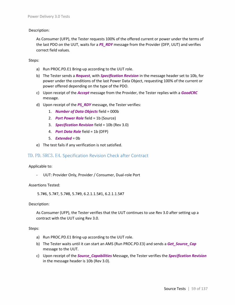
Power Delivery 3.0 Tests
Source Tests | 59 of 137
Description:
As Consumer (UFP), the Tester requests 100% of the offered current or power under the terms of
the last PDO on the UUT, waits for a PS_RDY message from the Provider (DFP, UUT) and verifies
correct field values.
Steps:
a) Run PROC.PD.E1 Bring-up according to the UUT role.
b) The Tester sends a Request, with Specification Revision in the message header set to 10b, for power under the conditions of the last Power Data Object, requesting 100% of the current or power offered depending on the type of the PDO.
c) Upon receipt of the Accept message from the Provider, the Tester replies with a GoodCRC message.
d) Upon receipt of the PS_RDY message, the Tester verifies:
1. Number of Data Objects field = 000b
2. Port Power Role field = 1b (Source)
3. Specification Revision field = 10b (Rev 3.0)
4. Port Data Role field = 1b (DFP)
5. Extended = 0b
e) The test fails if any verification is not satisfied.
TD.PD.SRC3.E4.Specification Revision Check after Contract
Applicable to:
- UUT: Provider Only, Provider / Consumer, Dual-role Port
Assertions Tested:
5.7#6, 5.7#7, 5.7#8, 5.7#9, 6.2.1.1.5#1, 6.2.1.1.5#7
Description:
As Consumer (UFP), the Tester verifies that the UUT continues to use Rev 3.0 after setting up a
contract with the UUT using Rev 3.0.
Steps:
a) Run PROC.PD.E1 Bring-up according to the UUT role.
b) The Tester waits until it can start an AMS (Run PROC.PD.E3) and sends a Get_Source_Cap message to the UUT.
c) Upon receipt of the Source_Capabilities Message, the Tester verifies the Specification Revision in the message header is 10b (Rev 3.0).

Power Delivery 3.0 Tests
Source Tests | 60 of 137
TD.PD.SRC3.E5.Source_Capabilities_Extended sent timely
Applicable to:
- UUT: Provider Only, Provider / Consumer, Dual-role Port
Assertions Tested:
6.12.1#6, 8.3.3.8.2.1#1, 8.3.3.8.2.1#2
Description:
As Consumer (UFP), the Tester verifies that the UUT replies Get_Source_Cap_Extended message
with a Source_Capabilities_Extended message timely.
Steps:
a) Run PROC.PD.E1 Bring-up according to the UUT role.
b) The Tester waits until it can start an AMS (Run PROC.PD.E3) and sends a Get_Source_Cap_Extended message to the UUT.
c) If a Source_Capabilities_Extended or Not_Supported message is not received within tReceiverResponse max, the test fails. This delay is measured from the time the last bit of Get_Source_Cap_Extended message EOP has been transmitted to the time the first bit of the Source_Capabilities_Extended message preamble has been received.
TD.PD.SRC3.E6.Source_Capabilities_Extended Fields Checks
Applicable to:
- UUT: Provider Only, Provider / Consumer, Dual-role Port
Assertions Tested:
6.2.1.1.1#1, 6.2.1.1.1#2, 6.2.1.1.1#4, 6.2.1.1.2#3, 6.2.1.1.2#4, 6.2.1.1.5#7, 6.2.1.1.8#1, 6.2.1.2#1,
6.2.1.2#3, 6.2.1.2.1#1, 6.2.1.2.1#2, 6.2.1.2.1#4, 6.2.1.2.1#6, 6.2.1.2.1#7, 6.2.1.2.2#1, 6.2.1.2.2#2,
6.2.1.2.3#1, 6.2.1.2.3#3, 6.2.1.2.4#1, 6.2.1.2.4#3, 6.4.1.2.2.7#5, 6.5#1, 6.5.1#1, 6.5.1.13#2,
6.5.1.13#3
Description:
As Consumer (UFP), the Tester sends a Get_Source_Cap_Extended message to the UUT, waits for a
Source_Capabilities_Extended message from the UUT and verifies correct field values.
Steps:
a) Run PROC.PD.E1 Bring-up according to the UUT role. The Tester sets Unchunked Extended Messages Supported to 1 in Request message during this process.
b) The Tester waits until it can start an AMS (Run PROC.PD.E3) and sends a Get_Source_Cap_Extended message to the UUT.

Power Delivery 3.0 Tests
Source Tests | 61 of 137
c) If a Not_Supported message is received, the test passes and stops here.
d) Upon receipt of the Source_Capabilities_Extended message, the Tester verifies:
1. Port Power Role field = 1b (Source)
2. Specification Revision field = 10b (Rev 3.0)
3. Port Data Role field = 1b (DFP)
4. Extended = 1b
5. Chunk Number in Extended Message Header = 0
6. Request Chunk in Extended Message Header = 0
7. Bit 9 (Reserved) in Extended Message Header = 0
8. Data Size in Extended Message Header = 24
9. If both UUT and the Tester support unchunked extended messages
Chunked bit in Extended Message Header = 0
Number of Data Objects field = 000b
10. If either the UUT or the Tester doesn’t support unchunked extended messages
Chunked bit in Extended Message Header = 1
Number of Data Objects field = 7
The total number of data bytes is consistent with the Number of Data Objects field
The last 2 bytes of the 7th Data Object are 0
11. For the SCEDB
Bits 0..1 of Voltage Regulation field = 00b or 01b
Bits 3..7 (Reserved) of Voltage Regulation filed are 0
Bits 3..7 (Reserved) of Compliance field are 0
Bits 3..7 (Reserved) of Touch Current field are 0
Touch Temp field is 0, 1 or 2
If bit 0 of Source Inputs field is 0, bit 1 is 0
Bits 3..7 (Reserved) of Source Inputs field are 0
Upper Nibble of Number of Batteries/Battery Slots field (Number of Hot Swappable Battery Slots) <= 4
Lower Nibble of Number of Batteries/Battery Slots field (Number of Fixed Batteries) <= 4
Bit 7 (Reserved) of Source PDP field is 0
12. If any field of Peak Current1, Peak Current2, or Peak Current3 in the SCEDB is not 0, the Tester verifies Peak Current is set to 0 in the Source_Capabilities message from the UUT.
e) Rerun the test, with Unchunked Extended Messages Supported set to 0 in step a)

Power Delivery 3.0 Tests
Source Tests | 62 of 137
TD.PD.SRC3.E7.Battery Status sent timely
Applicable to:
- UUT: Provider Only, Provider / Consumer, Dual-role Port
Assertions Tested:
6.4.5#1, 6.12.2#4, 8.3.3.11.2.1#1, 8.3.3.11.2.1#2
Description:
As Consumer (UFP), the Tester verifies that the UUT replies Get_Battery_Status message with a
Battery_Status message timely.
Steps:
a) Run PROC.PD.E1 Bring-up according to the UUT role.
b) The Tester waits until it can start an AMS (Run PROC.PD.E3) and sends a Get_Source_Cap_Extended message to the UUT.
c) If a Not_Supported message is received, and Num_Fixed_Batteries and Num_Swappable_Battery_Slots in the VIF are 0, the test passes and stops here.
d) If the Number of Batteries/Battery Slots field in the returned Source_Capabilities_Extended message is 0, the test passes and stops here.
e) The Tester waits until it can start an AMS (Run PROC.PD.E3) and sends a Get_Battery_Status message to the UUT.
f) If a Battery_Status message is not received within tReceiverResponse max, the test fails. This delay is measured from the time the last bit of Get_Battery_Status message EOP has been transmitted to the time the first bit of the Battery_Status message preamble has been received.
TD.PD.SRC3.E8.Battery Status Fields Checks
Applicable to:
- UUT: Provider Only, Provider / Consumer, Dual-role Port
Assertions Tested:
6.2.1.1.1#1, 6.2.1.1.8#1, 6.4.5#3, 6.4.5#4, 6.4.5#5, 6.4.5#6, 6.4.5.2#1, 6.4.5.2#2, 6.4.5.2.2#1,
6.4.5.2.2#2, 6.4.5.2.3#1, 6.4.5.2.3#2
Description:
As Consumer (UFP), the Tester sends a Get_Battery_Status message to the UUT, verifies the UUT
respond with a Battery_Status or Not_Supported message. If a Battery_Status message is
received, the Tester verifies correct field values.

Power Delivery 3.0 Tests
Source Tests | 63 of 137
Steps:
a) Run PROC.PD.E1 Bring-up according to the UUT role.
b) The Tester waits until it can start an AMS (Run PROC.PD.E3) and sends a Get_Source_Cap_Extended message to the UUT.
c) If a Source_Capabilities_Extended message is received, the Tester record the Number of Batteries/Battery Slots field. If a Not_Supported message is received, the Tester reads the Number of Batteries/Battery Slots field (combine Num_Fixed_Batteries and Num_Swappable_Battery_Slots) from the VIF.
d) The Tester waits until it can start an AMS (Run PROC.PD.E3) and sends a Get_Battery_Status message to the UUT, with Battery Status Ref set to 0.
e) The Tester verifies a Not_Supported or Battery_Status message is received within tReceiverResponse max, and the UUT always replies with the same message type. i.e. The UUT cannot replies with a Not_Supported message sometimes and Battery_Status message other times.
f) If a Battery_Status message is received, the Tester verifies:
1. Number of Data Objects field = 001b
2. Port Power Role field = 1b (Source)
3. Specification Revision field = 10b (Rev 3.0)
4. Port Data Role field = 1b (DFP)
5. Extended = 0b
6. Invalid Battery Reference field (Bit 0) of the Battery Info field in the BSDO matches with the recorded Number of Batteries/Battery Slots field
7. If Battery Status Ref referred to a fixed battery and Invalid Battery Reference field is 0, the Battery is present field (Bit 1) shall be 1
8. If Invalid Battery Reference field is 1, Battery is present field shall be 0
9. If Battery is present, Battery charging status (Bits 3..2) of Battery Info field is not 11b
10. If Battery is not present, Bits 3..2 of Battery Info field is 00b
11. Bits 7..4 of Battery Info field are 0
12. Bits 7..0 of the BSDO are 0
g) Rerun steps d) to f) with Battery Status Ref set to 1 - 7
TD.PD.SRC3.E9.Battery Status Fields Checks - Invalid Battery reference
Applicable to:
- UUT: Provider Only, Provider / Consumer, Dual-role Port
Assertions Tested:
6.2.1.1.1#1, 6.2.1.1.8#1, 6.4.5.2#1, 6.4.5.2#2, 6.4.5.2.1#1

Power Delivery 3.0 Tests
Source Tests | 64 of 137
Description:
As Consumer (UFP), the Tester sends a Get_Battery_Status message with an invalid battery
reference to the UUT, waits for a Battery_Status message from the Provider (DFP, UUT) and
verifies correct field values.
Steps:
a) Run PROC.PD.E1 Bring-up according to the UUT role.
b) The Tester waits until it can start an AMS (Run PROC.PD.E3) and sends a Get_Source_Cap_Extended message to the UUT.
c) If a Source_Capabilities_Extended message is returned, the Tester records the Number of Batteries/Battery Slots field. If a Not_Supported message is received, the Tester reads the Number of Batteries/Battery Slots field (combine Num_Fixed_Batteries and Num_Swappable_Battery_Slots) from the VIF.
d) The Tester waits until it can start an AMS (Run PROC.PD.E3) and sends a Get_Battery_Status message, with Battery Status Ref set to 8, to the UUT.
e) If a Not_Supported message is received, and
1. If the recorded Number of Batteries/Battery Slots field is 0, the test passes and stops here.
2. If the recorded Number of Batteries/Battery Slots field is not 0, the test fails.
f) Upon receipt of the Battery_Status message, the Tester verifies:
1. Number of Data Objects field = 001b
2. Port Power Role field = 1b (Source)
3. Specification Revision field = 10b (Rev 3.0)
4. Port Data Role field = 1b (DFP)
5. Extended = 0b
6. Invalid Battery Reference field (Bit 0) of the Battery Info field in the BSDO is 1
7. Bits 7..1 of Battery Info field in the BSDO are 0
8. Bits 7..0 of the BSDO are 0
TD.PD.SRC3.E10.Unrecognized Message Received in Ready State
Applicable to:
- UUT: Provider Only, Provider / Consumer, Dual-role Port
Assertions Tested:
6.3.14#1, 6.8.1#6, 8.3.3.5.1.1#1, 8.3.3.5.1.1#2

Power Delivery 3.0 Tests
Source Tests | 65 of 137
Description:
As Consumer (UFP), after setting up a contract with the UUT, the Tester sends an unrecognized
message, with a reserved message type, to the UUT, and verifies the UUT replies with a
Not_Supported message.
Steps:
a) Run PROC.PD.E1 Bring-up according to the UUT role.
b) The Tester waits until it can start an AMS (Run PROC.PD.E3) and sends a control message, with Message Type set to 01110 (Reserved), to the UUT.
c) If a Not_Supported message is not received within tReceiverResponse max, the test fails. This delay is measured from the time the last bit of unrecognized message EOP has been transmitted to the time the first bit of the Not_Supported message preamble has been received.
TD.PD.SRC3.E11.Get_Status Fields Checks
Applicable to:
- UUT: Provider Only, Provider / Consumer, Dual-role Port
Assertions Tested:
6.2.1.1.1#1, 6.2.1.1.5#7, 6.2.1.1.8#1, 8.3.3.7.4.1#1, 8.3.3.7.4.1#2, 8.3.3.7.4.1#3, 8.3.3.9.3.1#1,
8.3.3.9.3.1#2
Description:
As Consumer (UFP), after setting up a contract with the UUT, the Tester sends an Alert message to
the UUT, waits for a Get_Status message from the UUT and verifies correct field values.
Steps:
a) Run PROC.PD.E1 Bring-up according to the UUT role.
b) The Tester waits until it can start an AMS (Run PROC.PD.E3) and sends an Alert message to the UUT, with bit 5 of Type of Alert set to 1 (Source Input Change Event).
c) If a Not_Supported message is received, the test passes and stops here.
d) If a Get_Status message is not received within 500 ms after the Alert message was sent, the test passes and stops here.
e) Upon receipt of the Get_Status message, the Tester verifies:
1. Number of Data Objects field = 000b
2. Port Power Role field = 1b (Source)
3. Specification Revision field = 10b (Rev 3.0)
4. Port Data Role field = 1b (DFP)
5. Extended = 0b

Power Delivery 3.0 Tests
Source Tests | 66 of 137
TD.PD.SRC3.E12.Get_Battery_Status Fields Checks
Applicable to:
- UUT: Provider Only, Provider / Consumer, Dual-role Port
Assertions Tested:
6.2.1.1.1#1, 6.2.1.1.1#2, 6.2.1.1.1#4, 6.2.1.1.2#3, 6.2.1.1.2#4, 6.2.1.1.5#7, 6.2.1.1.8#1, 6.2.1.2#1,
6.2.1.2#3, 6.2.1.2.1#1, 6.2.1.2.1#2, 6.2.1.2.1#4, 6.2.1.2.1#6, 6.2.1.2.1#7, 6.2.1.2.2#1, 6.2.1.2.2#2,
6.2.1.2.3#1, 6.2.1.2.3#3, 6.2.1.2.4#1, 6.2.1.2.4#3, 6.5#1, 6.5.4#2, 6.5.4#3, 8.3.3.7.4.1#1,
8.3.3.7.4.1#2, 8.3.3.7.4.1#3, 8.3.3.11.1.1#1, 8.3.3.11.1.1#2
Description:
As Consumer (UFP), after setting up a contract with the UUT, the Tester sends an Alert message to
the UUT, waits for a Get_Battery_Status message from the UUT and verifies correct field values.
Steps:
a) Run PROC.PD.E1 Bring-up according to the UUT role. The Tester sets Unchunked Extended Messages Supported to 1 in Request message during this process.
b) The Tester waits until it can start an AMS (Run PROC.PD.E3) and sends an Alert message to the UUT, with bit 1 (Battery Status Change Event) of Type of Alert set to 1, and B20 set to 1 (Battery 0).
c) If a Not_Supported message is received, the test passes and stops here.
d) If a Get_Battery_Status message is not received within 500 ms after the Alert message was sent, the test passes and stops here.
e) Upon receipt of the Get_Battery_Status message, the Tester verifies:
1. Port Power Role field = 1b (Source)
2. Specification Revision field = 10b (Rev 3.0)
3. Port Data Role field = 1b (DFP)
4. Extended = 1b
5. Chunk Number in Extended Message Header = 0
6. Request Chunk in Extended Message Header = 0
7. Bit 9 (Reserved) in Extended Message Header = 0
8. Data Size in Extended Message Header = 1
9. If both the UUT and the Tester supports unchunked extended messages
Chunked bit in Extended Message Header = 0
Number of Data Objects field = 000b
10. If either the UUT or the Tester doesn’t support unchunked extended messages
Chunked bit in Extended Message Header = 1
Number of Data Objects field = 001b

Power Delivery 3.0 Tests
Source Tests | 67 of 137
The total number of data bytes is consistent with the Number of Data Objects field
The last byte of the Data Object is 0
11. Battery Status Ref = 0
f) Rerun the test, with Unchunked Extended Messages Supported set to 0 in step a)
TD.PD.SRC3.E13.Status sent timely
Applicable to:
- UUT: Provider Only, Provider / Consumer, Dual-role Port
Assertions Tested:
6.3.16#1, 6.5.2#1, 8.3.3.9.2.1#1, 8.3.3.9.2.1#2
Description:
As Consumer (UFP), the Tester verifies that the UUT replies Get_Status message with a Status
message timely.
Steps:
a) Run PROC.PD.E1 Bring-up according to the UUT role.
b) The Tester waits until it can start an AMS (Run PROC.PD.E3) and sends a Get_Status message to the UUT.
c) If a Status or Not_Supported message is not received within tReceiverResponse max, the test fails. This delay is measured from the time the last bit of Get_Status message EOP has been transmitted to the time the first bit of the Status message preamble has been received.
TD.PD.SRC3.E14.Status Fields Checks
Applicable to:
- UUT: Provider Only, Provider / Consumer, Dual-role Port
Assertions Tested:
6.2.1.1.1#1, 6.2.1.1.1#2, 6.2.1.1.1#4, 6.2.1.1.2#3, 6.2.1.1.2#4, 6.2.1.1.5#7, 6.2.1.1.8#1, 6.2.1.2#1,
6.2.1.2#3, 6.2.1.2.1#1, 6.2.1.2.1#2, 6.2.1.2.1#4, 6.2.1.2.1#6, 6.2.1.2.1#7, 6.2.1.2.2#1, 6.2.1.2.2#2,
6.2.1.2.3#1, 6.2.1.2.3#3, 6.2.1.2.4#1, 6.2.1.2.4#3, 6.5#1, 6.5.2#2, 6.5.2#4, 6.5.2.4#2, 6.5.2.5#1
Description:
As Consumer (UFP), the Tester sends a Get_Status message to the UUT, waits for a Status message
from the UUT and verifies correct field values.

Power Delivery 3.0 Tests
Source Tests | 68 of 137
Steps:
a) Run PROC.PD.E1 Bring-up according to the UUT role. The Tester sets Unchunked Extended Messages Supported to 1 in Request message during this process.
b) The Tester waits until it can start an AMS (Run PROC.PD.E3) and sends a Get_Status message to the UUT.
c) If a Not_Supported message is received, the test passes and stops here.
d) Upon receipt of the Status message, the Tester verifies:
1. Port Power Role field = 1b (Source)
2. Specification Revision field = 10b (Rev 3.0)
3. Port Data Role field = 1b (DFP)
4. Extended = 1b
5. Chunk Number in Extended Message Header = 0
6. Request Chunk in Extended Message Header = 0
7. Bit 9 (Reserved) in Extended Message Header = 0
8. Data Size in Extended Message Header = 5 or 6
9. If both the UUT and the Tester support unchunked extended messages
Chunked bit in Extended Message Header = 0
Number of Data Objects field = 000b
10. If either the UUT or the Tester doesn’t support unchunked extended messages
Chunked bit in Extended Message Header = 1
Number of Data Objects field = 2
The total number of data bytes is consistent with the Number of Data Objects field
The last 1 byte of the 2nd Data Object has zero value if Data Size (in Extended Message Header) = 5
11. For the SDB
Bit 0 of Present Input field = 0
Bits 5..7 of Present Input field are 0
If bit 3 of Present Input field is 0, Present Battery Input field shall be 0
Bit 0 and Bits 5..7 of Event Flags field are 0
OVT Event is not set in Event Flags field
Bit 0, Bits 3..7 of Temperature Status field are 0
Bit 0, Bits 6..7 of Power Status field are 0
If OTP event is set in Event Flags, Temperature Status shall be Over temperature. And vice versa.
e) Rerun the test, with Unchunked Extended Messages Supported set to 0 in step a)

Power Delivery 3.0 Tests
Source Tests | 69 of 137
TD.PD.SRC3.E15.Battery_Capabilities sent timely
Applicable to:
- UUT: Provider Only, Provider / Consumer, Dual-role Port
Assertions Tested:
6.5.3#1, 6.12.3#3, 8.3.3.10.2.1#1, 8.3.3.10.2.1#2
Description:
As Consumer (UFP), the Tester verifies that the UUT replies Get_Battery_Cap message with a
Battery_Capabilities message timely.
Steps:
a) Run PROC.PD.E1 Bring-up according to the UUT role.
b) The Tester waits until it can start an AMS (Run PROC.PD.E3) and sends a Get_Source_Cap_Extended message to the UUT.
c) If a Not_Supported message is received, and the Num_Fixed_Batteries and Num_Swappable_Battery_Slots in the VIF are 0, the test passes and stops here.
d) If the Number of Batteries/Battery Slots field in the returned Source_Capabilities_Extended message is 0, the test passes and stops here.
e) The Tester waits until it can start an AMS (Run PROC.PD.E3) and sends a Get_Battery_Cap message to the UUT.
f) If a Battery_Capabilities message is not received within tReceiverResponse max, the test fails. This delay is measured from the time the last bit of Get_Battery_Cap message EOP has been transmitted to the time the first bit of the Battery_Capabilities message preamble has been received.
TD.PD.SRC3.E16.Battery_Capabilities Fields Checks
Applicable to:
- UUT: Provider Only, Provider / Consumer, Dual-role Port
Assertions Tested:
6.2.1.1.1#1, 6.2.1.1.1#2, 6.2.1.1.1#4, 6.2.1.1.2#3, 6.2.1.1.2#4, 6.2.1.1.5#7, 6.2.1.1.8#1, 6.2.1.2#1,
6.2.1.2#3, 6.2.1.2.1#1, 6.2.1.2.1#2, 6.2.1.2.1#4, 6.2.1.2.1#6, 6.2.1.2.1#7, 6.2.1.2.2#1, 6.2.1.2.2#2,
6.2.1.2.3#1, 6.2.1.2.3#3, 6.2.1.2.4#1, 6.2.1.2.4#3, 6.5#1, 6.5.5#2, 6.5.5.3.2#1
Description:
As Consumer (UFP), the Tester sends a Get_Battery_Cap message, verifies the UUT respond with a
Battery_Capabilities or Not_Supported message. If a Battery_Capabilities is received, the Tester
verifies correct field values.

Power Delivery 3.0 Tests
Source Tests | 70 of 137
Steps:
a) Run PROC.PD.E1 Bring-up according to the UUT role. The Tester sets Unchunked Extended Messages Supported to 1 in Request message during this process.
b) The Tester waits until it can start an AMS (Run PROC.PD.E3) and sends a Get_Source_Cap_Extended message to the UUT.
c) If a Source_Capabilities_Extended message is received, the Tester record the Number of Batteries/Battery Slots field. If a Not_Supported message is received, the Tester reads the Number of Batteries/Battery Slots field (combine Num_Fixed_Batteries and Num_Swappable_Battery_Slots) from the VIF.
d) The Tester waits until it can start an AMS (Run PROC.PD.E3) and sends a Get_Battery_Cap message to the UUT, with Battery Cap Ref set to 0.
e) The Tester verifies a Not_Supported or Battery_Capabilities message is received within tReceiverResponse max, and the UUT always replies with the same message type. i.e. The UUT cannot replies with a Not_Supported message sometimes and Battery_Capabilities message other times.
f) If a Battery_Capabilities message is received, the Tester verifies:
1. Port Power Role field = 1b (Source)
2. Specification Revision field = 10b (Rev 3.0)
3. Port Data Role field = 1b (DFP)
4. Extended = 1b
5. Chunk Number in Extended Message Header = 0
6. Request Chunk in Extended Message Header = 0
7. Bit 9 (Reserved) in Extended Message Header = 0
8. Data Size in Extended Message Header = 9
9. If both the UUT and the Tester supports unchunked extended messages
Chunked bit in Extended Message Header = 0
Number of Data Objects field = 000b
10. If either the UUT or the Tester doesn’t support unchunked extended messages
Chunked bit in Extended Message Header = 1
Number of Data Objects field = 3
The total number of data bytes is consistent with the Number of Data Objects field
The last byte of the 3rd Data Object is 0
11. For the BCDB
Invalid Battery reference bit of Battery Type field matches with the recorded Number of Batteries/Battery Slots field
Bits 1..7 of Battery Type field are 0
g) Rerun steps d) to f) with Battery Cap Ref set to 1 - 7

Power Delivery 3.0 Tests
Source Tests | 71 of 137
h) Rerun the test, not including step g), with Unchunked Extended Messages Supported set to 0 in step a)
TD.PD.SRC3.E17.Battery_Capabilities Fields Checks - Invalid Battery Reference
Applicable to:
- UUT: Provider Only, Provider / Consumer, Dual-role Port
Assertions Tested:
6.2.1.1.1#1, 6.2.1.1.1#2, 6.2.1.1.1#4, 6.2.1.1.2#3, 6.2.1.1.2#4, 6.2.1.1.5#7, 6.2.1.1.8#1, 6.2.1.2#1,
6.2.1.2#3, 6.2.1.2.1#1, 6.2.1.2.1#2, 6.2.1.2.1#4, 6.2.1.2.1#6, 6.2.1.2.1#7, 6.2.1.2.2#1, 6.2.1.2.2#2,
6.2.1.2.3#1, 6.2.1.2.3#3, 6.2.1.2.4#1, 6.2.1.2.4#3, 6.5#1, 6.5.5#2, 6.5.5.3.1#1
Description:
As Consumer (UFP), the Tester sends a Get_Battery_Cap message with an invalid Battery
Reference to the UUT, waits for a Battery_Capabilities message from the UUT, and verifies correct
field values.
Steps:
a) Run PROC.PD.E1 Bring-up according to the UUT role. The Tester sets Unchunked Extended Messages Supported to 1 in Request message during this process.
b) The Tester waits until it can start an AMS (Run PROC.PD.E3) and sends a Get_Source_Cap_Extended message to the UUT.
c) If a Source_Capabilities_Extended message is returned, the Tester records the Number of Batteries/Battery Slots field. If a Not_Supported message is received, the Tester reads the Number of Batteries/Battery Slots field (combine Num_Fixed_Batteries and Num_Swappable_Battery_Slots) from the VIF.
d) The Tester waits until it can start an AMS (Run PROC.PD.E3) and sends a Get_Battery_Cap message, in which Battery Cap Ref is set to 8, to the UUT.
e) If a Not_Supported message is received, and
1. If the recorded Number of Batteries/Battery Slots field is 0, the test passes and stops here.
2. If the recorded Number of Batteries/Battery Slots field is not 0, the test fails.
f) Upon receipt of the Battery_Capabilities message, the Tester verifies:
1. Port Power Role field = 1b (Source)
2. Specification Revision field = 10b (Rev 3.0)
3. Port Data Role field = 1b (DFP)
4. Extended = 1b
5. Chunk Number in Extended Message Header = 0
6. Request Chunk in Extended Message Header = 0
7. Bit 9 (Reserved) in Extended Message Header = 0

Power Delivery 3.0 Tests
Source Tests | 72 of 137
8. Data Size in Extended Message Header = 9
9. If both the UUT and the Tester support unchunked extended messages
Chunked bit in Extended Message Header = 0
Number of Data Objects field = 000b
10. If either the UUT or the Tester doesn’t support unchunked extended messages
Chunked bit in Extended Message Header = 1
Number of Data Objects field = 3
The total number of data bytes is consistent with the Number of Data Objects field
The last byte of the 3rd Data Object is 0
11. For the BCDB
Invalid Battery reference bit of Battery Type field = 1
Bits 1..7 of Battery Type field are 0
g) Rerun the test, with Unchunked Extended Messages Supported set to 0 in step a)
TD.PD.SRC3.E18.Manufacturer_Info Sent Timely
Applicable to:
- UUT: Provider Only, Provider / Consumer, Dual-role Port
Assertions Tested:
6.5.6#1, 6.5.7#1, 8.3.3.12.2.1#1, 8.3.3.12.2.1#2
Description:
As Consumer (UFP), the Tester verifies that the UUT replies Get_Manufacturer_Info message with
a Manufacturer_Info message timely.
Steps:
a) Run PROC.PD.E1 Bring-up according to the UUT role.
b) The Tester waits until it can start an AMS (Run PROC.PD.E3) and sends a Get_Manufacturer_Info message to the UUT.
c) If a Manufacturer_Info or Not_Supported message is not received within tReceiverResponse max, the test fails. This delay is measured from the time the last bit of Get_Manufacturer_Info message EOP has been transmitted to the time the first bit of the Manufacturer_Info message preamble has been received.

Power Delivery 3.0 Tests
Source Tests | 73 of 137
TD.PD.SRC3.E19.Manufacturer_Info Fields Checks
Applicable to:
- UUT: Provider Only, Provider / Consumer, Dual-role Port
Assertions Tested:
6.2.1.1.1#1, 6.2.1.1.1#2, 6.2.1.1.1#4, 6.2.1.1.2#3, 6.2.1.1.2#4, 6.2.1.1.5#7, 6.2.1.1.8#1, 6.2.1.2#1,
6.2.1.2#3, 6.2.1.2.1#1, 6.2.1.2.1#2, 6.2.1.2.1#4, 6.2.1.2.1#6, 6.2.1.2.1#7, 6.2.1.2.2#1, 6.2.1.2.2#2,
6.2.1.2.3#1, 6.2.1.2.3#3, 6.2.1.2.4#1, 6.2.1.2.4#3, 6.5#1
Description:
As Consumer (UFP), the Tester sends a Get_Manufacturer_Info message to the UUT, wait for a
Manufacturer_Info message from the UUT and verifies correct field values.
Steps:
a) Run PROC.PD.E1 Bring-up according to the UUT role. The Tester sets Unchunked Extended Messages Supported to 1 in Request message during this process.
b) The Tester waits until it can start an AMS (Run PROC.PD.E3) and sends a Get_Manufacturer_Info message, in which Manufacturer Info Target is set to 0, to the UUT.
c) If a Not_Supported message is received, the test passes and stops here.
d) Upon receipt of the Manufacturer_Info message, the Tester verifies:
1. Port Power Role field = 1b (Source)
2. Specification Revision field = 10b (Rev 3.0)
3. Port Data Role field = 1b (DFP)
4. Extended = 1b
5. Chunk Number in Extended Message Header = 0
6. Request Chunk in Extended Message Header = 0
7. Bit 9 (Reserved) in Extended Message Header = 0
8. Data Size in Extended Message Header is 4..26
9. If both the UUT and the Tester support unchunked extended messages
Chunked bit in Extended Message Header = 0
Number of Data Objects field = 000b
10. If either the UUT or the Tester doesn’t support unchunked extended messages
Chunked bit in Extended Message Header = 1
Number of Data Objects field = (Data Size + 5) / 4
The Packet payload is padded to the next 4-byte Data Object boundary with zeros (0x00).
e) Rerun the test, with Unchunked Extended Messages Supported set to 0 in step a)

Power Delivery 3.0 Tests
Source Tests | 74 of 137
TD.PD.SRC3.E20.Manufacturer_Info Fields Checks - Invalid Manufacturer Info Target
Applicable to:
- UUT: Provider Only, Provider / Consumer, Dual-role Port
Assertions Tested:
6.2.1.1.1#1, 6.2.1.1.1#2, 6.2.1.1.1#4, 6.2.1.1.2#3, 6.2.1.1.2#4, 6.2.1.1.5#7, 6.2.1.1.8#1, 6.2.1.2#1,
6.2.1.2#3, 6.2.1.2.1#1, 6.2.1.2.1#2, 6.2.1.2.1#4, 6.2.1.2.1#6, 6.2.1.2.1#7, 6.2.1.2.2#1, 6.2.1.2.2#2,
6.2.1.2.3#1, 6.2.1.2.3#3, 6.2.1.2.4#1, 6.2.1.2.4#3, 6.5#1, 6.5.7#2, 6.5.7.3#2
Description:
As Consumer (UFP), the Tester sends a Get_Manufacturer_Info message, in which Manufacturer
Info Target is set to 2, to the UUT, wait for a Manufacturer_Info message from the UUT and verifies
correct field values.
Steps:
a) Run PROC.PD.E1 Bring-up according to the UUT role. The Tester sets Unchunked Extended Messages Supported to 1 in Request message during this process.
b) The Tester waits until it can start an AMS (Run PROC.PD.E3) and sends a Get_Manufacturer_Info message, in which Manufacturer Info Target is set to 2, to the UUT.
c) If a Not_Supported message is received, the test passes and stops here.
d) Upon receipt of the Manufacturer_Info message, the Tester verifies:
1. Port Power Role field = 1b (Source)
2. Specification Revision field = 10b (Rev 3.0)
3. Port Data Role field = 1b (DFP)
4. Extended = 1b
5. Chunk Number in Extended Message Header = 0
6. Request Chunk in Extended Message Header = 0
7. Bit 9 (Reserved) in Extended Message Header = 0
8. Data Size in Extended Message Header is 18 (PID + VID + “Not Supported” + null)
9. If both the UUT and the Tester support unchunked extended messages
Chunked bit in Extended Message Header = 0
Number of Data Objects field = 000b
10. If either the UUT or the Tester doesn’t support unchunked extended messages
Chunked bit in Extended Message Header = 1
Number of Data Objects field = 5
The total number of data bytes is consistent with the Number of Data Objects field

Power Delivery 3.0 Tests
Source Tests | 75 of 137
11. Manufacturer String in Manufacturer Info Data Block = null terminated ASCII text string “Not Supported”
e) Rerun the test, with Unchunked Extended Messages Supported set to 0 in step a)
TD.PD.SRC3.E21.Manufacturer_Info Fields Checks - Invalid Manufacturer Info Ref
Applicable to:
- UUT: Provider Only, Provider / Consumer, Dual-role Port
Assertions Tested:
6.2.1.1.1#1, 6.2.1.1.1#2, 6.2.1.1.1#4, 6.2.1.1.2#3, 6.2.1.1.2#4, 6.2.1.1.5#7, 6.2.1.1.8#1, 6.2.1.2#1,
6.2.1.2#3, 6.2.1.2.1#1, 6.2.1.2.1#2, 6.2.1.2.1#4, 6.2.1.2.1#6, 6.2.1.2.1#7, 6.2.1.2.2#1, 6.2.1.2.2#2,
6.2.1.2.3#1, 6.2.1.2.3#3, 6.2.1.2.4#1, 6.2.1.2.4#3, 6.5#1, 6.5.7#2, 6.5.7.3#2
Description:
As Consumer (UFP), the Tester sends a Get_Manufacturer_Info message with an invalid
Manufacturer Info Ref to the UUT, waits for a Manufacturer_Info message from the UUT, and
verifies correct field values.
Steps:
a) Run PROC.PD.E1 Bring-up according to the UUT role. The Tester sets Unchunked Extended Messages Supported to 1 in Request message during this process.
b) The Tester waits until it can start an AMS (Run PROC.PD.E3) and sends a Get_Manufacturer_Info message, in which Manufacturer Info Target is set to 1 and Manufacturer Info Ref is set to 8, to the UUT.
c) If a Not_Supported message is received, the test passes and stops here.
d) Upon receipt of the Manufacturer_Info message, the Tester verifies:
1. Port Power Role field = 1b (Source)
2. Specification Revision field = 10b (Rev 3.0)
3. Port Data Role field = 1b (DFP)
4. Extended = 1b
5. Chunk Number in Extended Message Header = 0
6. Request Chunk in Extended Message Header = 0
7. Bit 9 (Reserved) in Extended Message Header = 0
8. Data Size in Extended Message Header is 18 (PID + VID + “Not Supported” + null)
9. If both the UUT and the Tester support unchunked extended messages
Chunked bit in Extended Message Header = 0
Number of Data Objects field = 000b
10. If either the UUT or the Tester doesn’t support unchunked extended messages
Chunked bit in Extended Message Header = 1

Power Delivery 3.0 Tests
Source Tests | 76 of 137
Number of Data Objects field = 5
The total number of data bytes is consistent with the Number of Data Objects field
11. Manufacturer String in Manufacturer Info Data Block = null terminated ASCII text string “Not Supported”
e) Rerun the test, with Unchunked Extended Messages Supported set to 0 in step a)
TD.PD.SRC3.E22.Cable Type Detection
Applicable to:
- UUT: Provider Only, Provider / Consumer, Dual-role Port
Assertions Tested:
4.4#1, 4.4#2, 4.4#5, 10.2.3.2#6
Description:
As Consumer (UFP), the Tester verifies that the UUT does cable detection if it offers currents in
excess of 3A and/or voltages in excess of 20V.
Steps:
a) If Captive_Cable is set to YES in the VIF, the test passes and stops here.
b) The test starts in a disconnected state.
c) The Tester applies Rd and Ra and waits for a connection with the UUT.
d) If a SOP' Discover Identity message is received, the Tester replies as Passive Cable with Vbus Current Handling Capability set to 5A and Maximum VBus Voltage set to 50V.
e) Upon receipt of the Source_Capabilities message from the UUT, the Tester checks whether the UUT offers currents in excess of 3A and/or voltages in excess of 20V. If so and no SOP’ Discovery Identity message was received, the test fails; if not, the test passes and stops here.
f) The Tester removes all terminations and simulates a disconnection
g) The Tester applies Rd and Ra and waits for a connection with the UUT.
h) If a SOP' Discover Identity message is received, the Tester replies as Passive Cable with Vbus Current Handling Capability set to 3A and Maximum VBus Voltage set to 20V.
i) Upon receipt of the Source_Capabilities message from the UUT, the Tester checks whether the UUT offers currents in excess of 3A and/or voltages in excess of 20V. If so, the test fails.

Power Delivery 3.0 Tests
Source Tests | 77 of 137
TD.PD.SRC3.E23.Vconn Swap
Applicable to:
- UUT: Provider Only, Provider / Consumer, Dual-role Port
Assertions Tested:
6.3.3#4, 6.3.11#7, 6.3.11#8, 6.3.11#10, 6.3.11#11, 6.3.12.4#1, 6.3.12.4#2
Description:
As Consumer (UFP), the Tester verifies that the UUT accepts VCONN_Swap when it’s presently the
Vconn source.
Steps:
a) Run PROC.PD.E1 Bring-up according to the UUT role.
b) In addition to emulating a UFP, the Tester will also present Ra and will reply to SOP' Discover Identity as a Passive Cable with Vbus Current Handling Capability set to 5A and Maximum VBus Voltage set to 20V.
c) The Tester waits until it can start an AMS (Run PROC.PD.E3) and sends a VCONN_Swap message to the UUT.
d) If an Accept or Not_Supported message is not received within tReceiverResponse max, the test fails. This delay is measured from the time the last bit of VCONN_Swap message EOP has
been transmitted to the time the first bit of the Accept or Not_Supported message preamble
has been received.
e) The Tester verifies the UUT never sources VConn if the message received in d) is Not_Supported.
TD.PD.SRC3.E24.Unexpected Message Received in Ready State
Applicable to:
- UUT: Provider Only, Provider / Consumer, Dual-role Port
Assertions Tested:
6.8.1#4
Description:
As Consumer (UFP), after setting up a contract with the UUT, the Tester sends a unexpected
message, to the UUT, and verifies the UUT does Soft Reset.
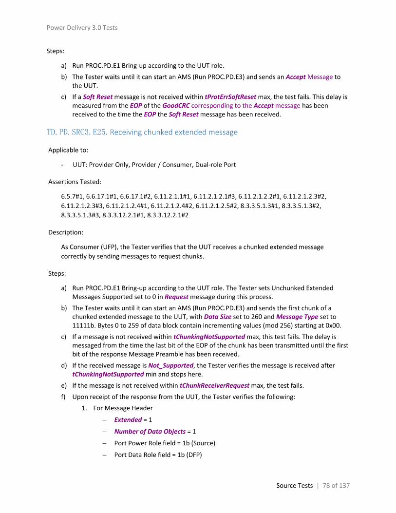
Power Delivery 3.0 Tests
Source Tests | 78 of 137
Steps:
a) Run PROC.PD.E1 Bring-up according to the UUT role.
b) The Tester waits until it can start an AMS (Run PROC.PD.E3) and sends an Accept Message to the UUT.
c) If a Soft Reset message is not received within tProtErrSoftReset max, the test fails. This delay is measured from the EOP of the GoodCRC corresponding to the Accept message has been received to the time the EOP the Soft Reset message has been received.
TD.PD.SRC3.E25.Receiving chunked extended message
Applicable to:
- UUT: Provider Only, Provider / Consumer, Dual-role Port
Assertions Tested:
6.5.7#1, 6.6.17.1#1, 6.6.17.1#2, 6.11.2.1.1#1, 6.11.2.1.2.1#3, 6.11.2.1.2.2#1, 6.11.2.1.2.3#2,
6.11.2.1.2.3#3, 6.11.2.1.2.4#1, 6.11.2.1.2.4#2, 6.11.2.1.2.5#2, 8.3.3.5.1.3#1, 8.3.3.5.1.3#2,
8.3.3.5.1.3#3, 8.3.3.12.2.1#1, 8.3.3.12.2.1#2
Description:
As Consumer (UFP), the Tester verifies that the UUT receives a chunked extended message
correctly by sending messages to request chunks.
Steps:
a) Run PROC.PD.E1 Bring-up according to the UUT role. The Tester sets Unchunked Extended Messages Supported set to 0 in Request message during this process.
b) The Tester waits until it can start an AMS (Run PROC.PD.E3) and sends the first chunk of a chunked extended message to the UUT, with Data Size set to 260 and Message Type set to 11111b. Bytes 0 to 259 of data block contain incrementing values (mod 256) starting at 0x00.
c) If a message is not received within tChunkingNotSupported max, this test fails. The delay is messaged from the time the last bit of the EOP of the chunk has been transmitted until the first bit of the response Message Preamble has been received.
d) If the received message is Not_Supported, the Tester verifies the message is received after tChunkingNotSupported min and stops here.
e) If the message is not received within tChunkReceiverRequest max, the test fails.
f) Upon receipt of the response from the UUT, the Tester verifies the following:
1. For Message Header
Extended = 1
Number of Data Objects = 1
Port Power Role field = 1b (Source)
Port Data Role field = 1b (DFP)

Power Delivery 3.0 Tests
Source Tests | 79 of 137
Specification Revision = 10b (Rev 3.0)
Message Type = 11111b
2. For Extended Message Header
Chunked = 1
Chunk Number = next chunk in the series
Request Chunk = 1
Bit 9 = 0 (Reserved)
Data Size = 0
g) The Tester sends the requested chunk to the UUT.
h) Repeat e) and g) until the Tester has finished sending all 10 chunks.
TD.PD.SRC3.E26.Soft_Reset sent regardless of Rp value
Applicable to:
- UUT: Provider Only, Provider / Consumer, Dual-role Port
Assertions Tested:
6.8.1#7
Description:
As Consumer (UFP), the Tester forces the UUT to send Soft_Reset and verifies Soft_Reset is sent
regardless of the Rp value is SinkTxOK or SinkTxNG.
Steps:
a) Run PROC.PD.E1 Bring-up according to the UUT role.
b) The Tester waits until it can start an AMS (Run PROC.PD.E3) and sends a Get_Source_Cap message to the UUT.
c) Upon receipt of the Source_Capabilities Message, the Tester doesn’t reply with GoodCRC.
d) The Tester verifies that a Soft_Reset message is sent by the UUT within tReceive max + tSoftReset max, the delay is measured from the time the last bit of the last retransmitted Source_Capabilities Message EOP has been received to the time the last bit of the Soft_Reset message EOP has been received.
TD.PD.SRC3.E27.PPS_Status Sent Timely
Applicable to:
- UUT: Provider Only, Provider / Consumer, Dual-role Port
Assertions Tested:
6.3.18#1, 6.5.10#1, 6.12.1#10, 6.12.3#10, 8.3.3.9.6.1#1, 8.3.3.9.6.1#2

Power Delivery 3.0 Tests
Source Tests | 80 of 137
Description:
As Consumer (UFP), the Tester verifies that the UUT replies Get_PPS_Status message with a
PPS_Status message timely.
Steps:
a) Run PROC.PD.E2 Bring-up procedure for PPS Tests according to the UUT role.
b) The Tester waits until it can start an AMS (Run PROC.PD.E3) and sends a Get_PPS_Status message to the UUT.
c) If a PPS_Status message is not received within tReceiverResponse max, the test fails. This delay is measured from the time the last bit of Get_PPS_Status message EOP has been transmitted to the time the first bit of the PPS_Status message preamble has been received.
TD.PD.SRC3.E28.PPS_Status Fields Check
Applicable to:
- UUT: Provider Only, Provider / Consumer, Dual-role Port
Assertions Tested:
6.5.10#3, 6.5.10.1#1, 6.5.10.1#2, 6.5.10.2#1, 6.5.10.2#2, 6.5.10.3#1, 6.5.10.3#2
Description:
As Consumer (UFP), the Tester sends a Get_PPS_Status message to the UUT, wait for a PPS_Status
message from the UUT and verifies correct field values.
Steps:
a) Run PROC.PD.E2 Bring-up procedure for PPS Tests according to the UUT role. The Tester sets Unchunked Extended Messages Supported to 1 in Request message during this process.
b) The Tester doesn’t draw any current, waits until it can start an AMS (Run PROC.PD.E3) and sends a Get_PPS_Status message to the UUT.
c) Upon receipt of the PPS_Status message, the Tester verifies:
1. Port Power Role field = 1b (Source)
2. Specification Revision field = 10b (Rev 3.0)
3. Port Data Role field = 1b (DFP)
4. Extended = 1b
5. Chunk Number in Extended Message Header = 0
6. Request Chunk in Extended Message Header = 0
7. Bit 9 (Reserved) in Extended Message Header = 0
8. Data Size in Extended Message Header is 4
9. If both the UUT and the Tester support unchunked extended messages

Power Delivery 3.0 Tests
Source Tests | 81 of 137
Chunked bit in Extended Message Header = 0
Number of Data Objects field = 000b
10. If either the UUT or the Tester doesn’t support unchunked extended messages
Chunked bit in Extended Message Header = 1
Number of Data Objects field = 2
The total number of data bytes is consistent with the Number of Data Objects field
The last 2 bytes of the 2nd Data object are 0
11. For the PPSSDB
Output Voltage field shall be within ±3% of the actual output voltage rounded to the nearest 20mV or 0xFFFF
Output Current field shall be 0x00 to 0x03(inclusive) or 0xFF
For Real Time Flags field
o Bit 0 shall be 0
o PTF shall be 0x00 (Not Supported) or 0x01 (Normal)
o OMF shall be 0 (Constant Voltage mode)
o Bits 4..7 shall be 0
d) Rerun the test, with Unchunked Extended Messages Supported set to 0 in step a)
TD.PD.SRC3.E29.SourcePPSCommTimer Deadline
Applicable to:
- UUT: Provider Only, Provider / Consumer, Dual-role Port
Assertions Tested:
6.6.18.2#1, 6.6.18.2#2, 6.6.18.2#3, 6.6.18.2#4
Description:
As Consumer (UFP), the Tester sends the second Request message after tPPSRequest max, verifies
SourcePPSCommTimer is not timeout at the UUT and the timer is correctly reinitialized.
Steps:
a) Run PROC.PD.E2 Bring-up procedure for PPS Tests according to the UUT role.
b) If a Hard Reset is received within tPPSRequest max, the test fails. The delay is measured from the time the last bit of the EOP of the GoodCRC Message sent by the UUT in response to the previous Request Message to the time the first bit of the Hard Reset is received.
c) The Tester sends the second Request Message to request the PPS APDO at 4V 1A, tPPSRequest max after the previous Request Message, and verifies the UUT responds with an Accept and

Power Delivery 3.0 Tests
Source Tests | 82 of 137
then PS_RDY message. If the Tester cannot send the second Request Message because it cannot start an AMS, the test fails.
d) If a Hard Reset is received within tPPSRequest max, the test fails. The delay is measured from the time the last bit of the EOP of the GoodCRC Message sent by the UUT in response to the second Request Message to the time the first bit of the Hard Reset is received.
TD.PD.SRC3.E30.SourcePPSCommTimer Timeout
Applicable to:
- UUT: Provider Only, Provider / Consumer, Dual-role Port
Assertions Tested:
6.4.1.2#10, 6.6.18.2#1, 6.6.18.2#2, 6.6.18.2#5, 8.3.3.2.6#6
Description:
As Consumer (UFP), the Tester intentionally does not send the second Request message, in order to
force a SourcePPSCommTimer timeout on the UUT and verifies it is correctly implemented.
Steps:
a) Run PROC.PD.E2 Bring-up procedure for PPS Tests according to the UUT role.
b) The Tester intentionally does not send the second Request Message, if a Hard Reset is received before tPPSTimeout min, or not received within tPPSTimeout max, the test fails. The delay is measured from the time the last bit of the EOP of the GoodCRC Message sent by the UUT in response to the previous Request Message to the time the first bit of the Hard Reset is received.
TD.PD.SRC3.E31.SourcePPSCommTimer Stopped
Applicable to:
- UUT: Provider Only, Provider / Consumer, Dual-role Port
Assertions Tested:
6.4.1.2#11, 6.6.18.2#1
Description:
As Consumer (UFP), the Tester request a PPS APDO first and then request a fixed PDO, verifies
SourcePPSCommTimer is stopped at the UUT.
Steps:
a) Run PROC.PD.E2 Bring-up procedure for PPS Tests according to the UUT role.

Power Delivery 3.0 Tests
Source Tests | 83 of 137
b) The Tester wait till it can start an AMS and sends the second Request Message to request the fixed PDO at 5V 0.5A, and verifies the UUT responds with an Accept and then PS_RDY message.
c) If a Hard Reset is received within tPPSTimeout max, the test fails. The delay is measured from the time the last bit of the EOP of the GoodCRC Message sent by the UUT in response to the second Request Message to the time the first bit of the Hard Reset is received.
TD.PD.SRC3.E32.ChunkSenderResponseTimer Timeout
Applicable to:
- UUT: Provider Only, Provider / Consumer, Dual-role Port
Assertions Tested:
6.6.17.3#1, 6.6.17.3#2, 6.6.17.3#5, 6.11.2.1.2.5#1, 6.11.2.1.2.5#3, 6.11.2.1.2.6#4
Description:
As Consumer (UFP), the Tester verifies that the UUT recovers correctly after the Tester stops
sending chunked messages in the middle.
Steps:
a) Run PROC.PD.E1 Bring-up according to the UUT role. The Tester sets Unchunked Extended Messages Supported set to 0 in Request message during this process.
b) The Tester waits until it can start an AMS (Run PROC.PD.E3) and sends the first chunk of a chunked extended message to the UUT, with Data Size set to 260 and Message Type set to 11111b. Bytes 0 to 259 of data block contain incrementing values (mod 256) starting at 0x00.
c) If a message is not received within tChunkingNotSupported max, this test fails. The delay is messaged from the time the last bit of the EOP of the chunk has been transmitted until the first bit of the response Message Preamble has been received.
d) If the received message is Not_Supported, the Tester verifies the message is received after tChunkingNotSupported min and stops here.
e) If the message is not received within tChunkReceiverRequest max, the test fails.
f) Upon receipt of the message from the UUT to request for the next chunk, the Tester sends the requested chunk to the UUT.
g) Repeat f) until the Tester has finished sending 4 chunks and intentionally does not send the 5th chunk to the UUT.
h) The Tester waits for tChunkSenderResponse max + 5 ms, waits until it can start an AMS (Run PROC.PD.E3) and sends the first chunk to the UUT.
i) If a message is not received within tChunkReceiverRequest max, the test fails.
j) Upon receipt of the message, the Tester verifies the following:
1. For Message Header
Extended = 1
Number of Data Objects = 1

Power Delivery 3.0 Tests
Source Tests | 84 of 137
Port Power Role field = 1b (Source)
Port Data Role field = 1b (DFP)
Specification Revision = 10b (Rev 3.0)
Message Type = 11111b
2. For Extended Message Header
Chunked = 1
Chunk Number = 1
Request Chunk = 1
Bit 9 = 0 (Reserved)
Data Size = 0
3. The total number of data bytes is consistent with the Number of Data Objects field
4. The last 2 bytes of the Data Object are 0
TD.PD.SRC3.E33.Country_Codes Sent Timely
Applicable to:
- UUT: Provider Only, Provider / Consumer, Dual-role Port
Assertions Tested:
6.3.19#1, 6.5.11#1, 8.3.3.13.2.1#1, 8.3.3.13.2.1#2
Description:
As Consumer (UFP), the Tester verifies that the UUT replies Get_Country_Codes message with a
Country_Codes or Not_Supported message timely.
Steps:
a) Run PROC.PD.E1 Bring-up according to the UUT role.
b) The Tester waits until it can start an AMS (Run PROC.PD.E3) and sends a Get_Country_Codes message to the UUT.
c) If a Country_Codes or Not_Supported message is not received within tReceiverResponse max, the test fails. This delay is measured from the time the last bit of Get_Country_Codes message EOP has been transmitted to the time the first bit of the Country_Codes message preamble has been received.

Power Delivery 3.0 Tests
Source Tests | 85 of 137
TD.PD.SRC3.E34.Country_Codes Fields Checks
Applicable to:
- UUT: Provider Only, Provider / Consumer, Dual-role Port
Assertions Tested:
6.5.11#2, 6.5.11.1#1
Description:
As Consumer (UFP), the Tester sends a Get_Country_Codes message to the UUT, wait for a
Country_Codes message from the UUT and verifies correct field values.
Steps:
a) Run PROC.PD.E1 Bring-up according to the UUT role. The Tester sets Unchunked Extended Messages Supported to 1 in Request message during this process.
b) The Tester waits until it can start an AMS (Run PROC.PD.E3) and sends a Get_Country_Codes message to the UUT.
c) If a Not_Supported message is received, the test passes and stops here.
d) Upon receipt of the Country_Codes message, the Tester verifies:
1. Port Power Role field = 1b (Source)
2. Specification Revision field = 10b (Rev 3.0)
3. Port Data Role field = 1b (DFP)
4. Extended = 1b
5. Request Chunk in Extended Message Header = 0
6. Bit 9 (Reserved) in Extended Message Header = 0
7. Data Size in Extended Message Header is 4..260, and is the same as that in the first Chunk
8. If both the UUT and the Tester support unchunked extended messages
Chunked bit in Extended Message Header = 0
Number of Data Objects field = 000b
Chunk Number in Extended Message Header = 0
The actual bytes in CCDB matches with Data Size
9. If either the UUT or the Tester doesn’t support unchunked extended messages
Chunked bit in Extended Message Header = 1
Chunk Number in Extended Message Header is correctly set
Number of Data Objects field = 7 or (Remaining Data Size + 5) / 4 (whichever is smaller)
The Packet payload is padded to the next 4-byte Data Object boundary with zeros (0x00) if this is the last Chunk.

Power Delivery 3.0 Tests
Source Tests | 86 of 137
10. For the CCDB
Length = (Data Size) / 2 – 1
All other bytes are ascii codes of capital letters (65 – 90 inclusive)
11. The Tester Requests for the next Chunk if the message is chunked and this is not the last Chunk, and go to step d)
e) Rerun the test, with Unchunked Extended Messages Supported set to 0 in step a)
TD.PD.SRC3.E35.Country_Info Sent Timely
Applicable to:
- UUT: Provider Only, Provider / Consumer, Dual-role Port
Assertions Tested:
6.5.12#1, 8.3.3.13.4.1#1, 8.3.3.13.4.1#2
Description:
As Consumer (UFP), the Tester verifies that the UUT replies Get_Country_Info message with a
Country_Info or Not_Supported message timely.
Steps:
a) Run PROC.PD.E1 Bring-up according to the UUT role.
b) The Tester waits until it can start an AMS (Run PROC.PD.E3) and sends a Get_Country_Codes message to the UUT.
c) If a Not_Supported message is received, the test passes and stops here.
d) For each Country Code, the Tester waits until it can start an AMS (Run PROC.PD.E3) and sends a Get_Country_Info message to the UUT.
e) If a Country_Info message is not received within tReceiverResponse max, the test fails. This delay is measured from the time the last bit of Get_Country_Info message EOP has been transmitted to the time the first bit of the Country_Info message preamble has been received.
f) If the Country_Info is chunked, the Tester finishes receiving the message.
TD.PD.SRC3.E36.Country_Info Fields Checks
Applicable to:
- UUT: Provider Only, Provider / Consumer, Dual-role Port
Assertions Tested:
6.5.12#2, 6.5.12.1#1

Power Delivery 3.0 Tests
Source Tests | 87 of 137
Description:
As Consumer (UFP), the Tester sends a Get_Country_Info message to the UUT, wait for a
Country_Info message from the UUT and verifies correct field values.
Steps:
a) Run PROC.PD.E1 Bring-up according to the UUT role. The Tester sets Unchunked Extended Messages Supported to 1 in Request message during this process.
b) The Tester waits until it can start an AMS (Run PROC.PD.E3) and sends a Get_Country_Codes message to the UUT.
c) If a Not_Supported message is received, the test passes and stops here.
d) For the first Country Code, the Tester waits until it can start an AMS (Run PROC.PD.E3) and sends a Get_Country_Info message to the UUT.
e) Upon receipt of the Country_Info message, the Tester verifies:
1. Port Power Role field = 1b (Source)
2. Specification Revision field = 10b (Rev 3.0)
3. Port Data Role field = 1b (DFP)
4. Extended = 1b
5. Request Chunk in Extended Message Header = 0
6. Bit 9 (Reserved) in Extended Message Header = 0
7. Data Size in Extended Message Header is 4..260, and is the same as that in the first Chunk
8. If both the UUT and the Tester support unchunked extended messages
Chunked bit in Extended Message Header = 0
Number of Data Objects field = 000b
Chunk Number in Extended Message Header = 0
The actual bytes in CIDB matches with Data Size
9. If either the UUT or the Tester doesn’t support unchunked extended messages
Chunked bit in Extended Message Header = 1
Chunk Number in Extended Message Header is correctly set
Number of Data Objects field = 7 or (Remaining Data Size + 5) / 4 (whichever is smaller)
The Packet payload is padded to the next 4-byte Data Object boundary with zeros (0x00) if this is the last Chunk.
10. For the CIDB
Country Code field is the same as that in the Get_Country_Info message
Byte 2 and Byte 3 are 0
11. The Tester Requests for the next Chunk if the message is chunked and this is not the last Chunk, and go to step d)

Power Delivery 3.0 Tests
Source Tests | 88 of 137
f) Rerun the test, with Unchunked Extended Messages Supported set to 0 in step a)

Power Delivery 3.0 Tests
Sink Tests | 89 of 137
Sink Tests
TD.PD.SNK3.E1.Request Fields Checks
Applicable to:
- UUT: Consumer Only, Consumer / Provider, Dual-role Port
Assertions Tested:
6.2.1.1.1#1, 6.2.1.1.5#1, 6.2.1.1.5#6, 6.2.1.1.8#1
Description:
As Provider, the Tester waits for a Request message from the UUT and verifies correct field values.
Steps:
a) Run PROC.PD.E1 Bring-up according to the UUT role until step e).
b) Upon receipt of the Request message, the Tester verifies:
1. Number of Data Objects field = 001b
2. MessageID field = 000b
3. Port Power Role field = 0b (Sink)
4. Port Data Role field = 0b (UFP)
5. Specification Revision field = 10b (Rev 3.0)
6. Extended Field = 0b
c) For the Sink Request Data Object, the Tester verifies:
1. Object position field is valid.
2. The Operating Current/Power is less than or equal to the maximum current/power offered in the Source_Capabilities Message.
3. If GiveBack flag is 0
The Maximum Operating Current/Power is larger than or equal to the Operating Current/Power.
If Capability Mismatch bit is 0, the Maximum Operating Current/Power is less than or equal to the maximum current/power offered in the Source_Capabilities Message.
4. If GiveBack flag is 1, the Minimum Operating Current/Power is less than the Operating Current/Power.
5. Bit 31 = 0b (Reserved)
6. Bits 22..20 = 000b (Reserved)
d) The test fails if any verification is not satisfied.

Power Delivery 3.0 Tests
Sink Tests | 90 of 137
TD.PD.SNK3.E2.Unrecognized Message Received in Ready State
Applicable to:
- UUT: Consumer Only, Consumer / Provider, Dual-role Port
Assertions Tested:
6.3.14#1, 6.8.1#6, 8.3.3.5.2.1#1, 8.3.3.5.2.1#2
Description:
As Provider (DFP), after setting up a contract with the UUT, the Tester sends an unrecognized
message, with a reserved Message Type, to the UUT, and verifies the UUT reply with a
Not_Supported message.
Steps:
a) Run PROC.PD.E1 Bring-up according to the UUT role.
b) The Tester sends a control message, with Message Type set to 01110, to the UUT.
c) If a Not_Supported message is not received within tReceiverResponse max, the test fails. This delay is measured from the time the last bit of unrecognized message EOP has been transmitted to the time the first bit of the Not_Supported message preamble has been received.
TD.PD.SNK3.E3.Get_Source_Cap_Extended Fields Checks
Applicable to:
- UUT: Consumer Only, Consumer / Provider, Dual-role Port
Assertions Tested:
6.2.1.1.1#1, 6.2.1.1.5#7, 6.4.1.2.2.7#6, 6.11.2.2.3.1#1, 6.11.2.2.3.1#2, 6.11.2.2.3.2#1, 8.3.3.8.1.1#1,
8.3.3.8.1.1#2
Description:
As Provider (DFP), after setting up a contract with the UUT, the Tester waits for a
Get_Source_Cap_Extended message from the Consumer (UUT) and verifies correct field values.
Steps:
a) Run PROC.PD.E1 Bring-up according to the UUT role. In Source_Capabilities message, the Tester sets Peak Current of fixed supply PDOs to 0.
b) The Tester sets termination to SinkTxOk.
c) If a Get_Source_Cap_Extended message is not received within 500 ms after termination set to SinkTxOk, the test passes and stops here.

Power Delivery 3.0 Tests
Sink Tests | 91 of 137
d) Upon receipt of the Get_Source_Cap_Extended message, the Tester verifies:
1. Number of Data Objects field = 000b
2. Port Power Role field = 0b (Sink)
3. Specification Revision field = 10b (Rev 3.0)
4. Port Data Role field = 0b (UFP)
5. Extended = 0b
TD.PD.SNK3.E4.SenderResponseTimer Deadline - Source_Capabilities_Extended
Applicable to:
- UUT: Consumer Only, Consumer / Provider, Dual-role Port
Assertions Tested:
8.3.3.8.1.1#1, 8.3.3.8.1.1#2, 8.3.3.8.1.1#3, 8.3.3.8.1.1#4
Description:
As Provider (DFP), the Tester verifies that the UUT accepts a Source_Capabilities_Extended
message sent at the deadline limit of tSenderResponse min in reply to Get_Source_Cap_Extended
message.
Steps:
a) Run PROC.PD.E1 Bring-up according to the UUT role. In Source_Capabilities message, the Tester sets Peak Current of fixed supply PDOs to 0.
b) The Tester sets termination to SinkTxOk.
c) If a Get_Source_Cap_Extended message is not received within 500 ms after termination set to SinkTxOk, the test passes and stops here.
d) Upon receipt of the Get_Source_Cap_Extended message from the UUT, the Tester replies with a GoodCRC message.
e) The Tester sends a Source_Capabilities_Extended message at the deadline limit of tSenderResponse min after the GoodCRC message. This delay is measured from the time the last bit of the GoodCRC message has been transmitted to the time the last bit of the Source_Capabilities_Extended message has been transmitted.
f) The Tester verifies a GoodCRC message corresponding to the Source_Capabilities_Extended message is received.
g) The Tester verifies a Soft Reset is not detected after tProtErrSoftReset max from the time the EOP of the GoodCRC sent in response to the Source_Capabilities_Extended message has been received.

Power Delivery 3.0 Tests
Sink Tests | 92 of 137
TD.PD.SNK3.E5.SenderResponseTimer Timeout - Source_Capabilities_Extended
Applicable to:
- UUT: Consumer Only, Consumer / Provider, Dual-role Port
Assertions Tested:
8.3.3.8.1.1#1, 8.3.3.8.1.1#2, 8.3.3.8.1.1#3, 8.3.3.8.1.1#4
Description:
As Provider (DFP), the Tester intentionally does not send the Source_Capabilities_Extended
message in reply to a Get_Source_Cap_Extended message from the UUT, in order to force a
SenderResponseTimer timeout on the UUT and verifies it is correctly implemented.
Steps:
a) Run PROC.PD.E1 Bring-up according to the UUT role. In Source_Capabilities message, the Tester sets Peak Current of fixed supply PDOs to 0.
b) The Tester sets termination to SinkTxOk.
c) If a Get_Source_Cap_Extended message is not received within 500 ms after termination set to SinkTxOk, the test passes and stops here.
d) Upon receipt of the Get_Source_Cap_Extended message from the UUT, the Tester replies with a GoodCRC message.
e) The Tester intentionally does not send the Source_Capabilities_Extended message in reply to the Get_Source_Cap_Extended message from the UUT, in order to force a SenderResponseTimer timeout on the UUT.
f) If a Hard Reset or Soft Reset is detected within tSenderResponse max from the time the last bit of the GoodCRC message EOP has been sent, the test fails.
TD.PD.SNK3.E6.Get_Status Fields Checks
Applicable to:
- UUT: Consumer Only, Consumer / Provider, Dual-role Port
Assertions Tested:
6.2.1.1.1#1, 6.2.1.1.5#7, 6.2.1.1.8#1, 6.11.2.2.3.1#1-2, 6.11.2.2.3.2#1, 8.3.3.7.2.1#1, 8.3.3.7.2.1#2,
8.3.3.7.2.1#3, 8.3.3.9.1.1#1, 8.3.3.9.1.1#2
Description:
As Provider (DFP), after setting up a contract with the UUT, the Tester sends an Alert message to
the UUT, waits for a Get_Status message from the Consumer (UUT) and verifies correct field
values.

Power Delivery 3.0 Tests
Sink Tests | 93 of 137
Steps:
a) Run PROC.PD.E1 Bring-up according to the UUT role.
b) The Tester sends an Alert message to the UUT, with bit 3 of Type of Alert set (OTP event).
c) The Tester sets termination to SinkTxOk.
d) If a Get_Status message is not received within 500 ms after termination set to SinkTxOk, the test passes and stops here.
e) Upon receipt of the Get_Status message, the Tester verifies:
1. Number of Data Objects field = 000b
2. Port Power Role field = 0b (Sink)
3. Specification Revision field = 10b (Rev 3.0)
4. Port Data Role field = 0b (UFP)
5. Extended = 0b
TD.PD.SNK3.E7.Get_Battery_Status Fields Checks
Applicable to:
- UUT: Consumer Only, Consumer / Provider, Dual-role Port
Assertions Tested:
6.2.1.1.1#1, 6.2.1.1.1#2, 6.2.1.1.1#4, 6.2.1.1.2#3, 6.2.1.1.2#4, 6.2.1.1.5#7, 6.2.1.1.8#1, 6.2.1.2#1,
6.2.1.2#3, 6.2.1.2.1#1, 6.2.1.2.1#2, 6.2.1.2.1#4, 6.2.1.2.1#6, 6.2.1.2.1#7, 6.2.1.2.2#1, 6.2.1.2.2#2,
6.2.1.2.3#3, 6.2.1.2.4#1, 6.2.1.2.4#3, 6.5#1, 6.5.4#2, 6.5.4#3, 6.11.2.2.3.1#1, 6.11.2.2.3.1#2,
6.11.2.2.3.2#1, 8.3.3.7.2.1#1, 8.3.3.7.2.1#2, 8.3.3.7.2.1#3, 8.3.3.11.1.1#1, 8.3.3.11.1.1#2
Description:
As Provider (DFP), after setting up a contract with the UUT, the Tester sends an Alert message to
the UUT, waits for a Get_Battery_Status message from the UUT and verifies correct field values.
Steps:
a) Run PROC.PD.E1 Bring-up according to the UUT role. The Tester sets Unchunked Extended Messages Supported to 1 in Source_Capabilities message during this process.
b) The Tester sends an Alert message to the UUT, with bit 1 (Battery Status Change Event) of Type of Alert set to 1, and B20 set to 1 (Battery 0).
c) The Tester sets termination to SinkTxOk.
d) If a Get_Battery_Status message is not received within 500 ms after the Alert message was sent, the test passes and stops here.
e) Upon receipt of the Get_Battery_Status message, the Tester verifies:
1. Port Power Role field = 0b (Sink)
2. Specification Revision field = 10b (Rev 3.0)

Power Delivery 3.0 Tests
Sink Tests | 94 of 137
3. Port Data Role field = 0b (UFP)
4. Extended = 1b
5. Chunk Number in Extended Message Header = 0
6. Request Chunk in Extended Message Header = 0
7. Bit 9 (Reserved) in Extended Message Header = 0
8. Data Size in Extended Message Header = 1
9. If both the UUT and the Tester support unchunked extended messages
Chunked bit in Extended Message Header = 0
Number of Data Objects field = 000b
10. If either the UUT or the Tester doesn’t support unchunked extended messages
Chunked bit in Extended Message Header = 1
Number of Data Objects field = 001b
The total number of data bytes is consistent with the Number of Data Objects field
The last byte of the Data Object is 0
11. Battery Status Ref = 0
f) Rerun the test, with Unchunked Extended Messages Supported set to 0 in step a)
TD.PD.SNK3.E8.Status sent timely
Applicable to:
- UUT: Consumer Only, Consumer / Provider, Dual-role Port
Assertions Tested:
6.3.16#1, 6.5.2#1, 8.3.3.9.4.1#1, 8.3.3.9.4.1#2
Description:
As Provider (DFP), the Tester verifies that the UUT replies Get_Status message with a Status
message timely.
Steps:
a) Run PROC.PD.E1 Bring-up according to the UUT role.
b) The Tester sends a Get_Status message to the UUT.
c) If a Status or Not_Supported message is not received within tReceiverResponse max, the test fails. This delay is measured from the time the last bit of Get_Status message EOP has been transmitted to the time the first bit of the Status message preamble has been received.

Power Delivery 3.0 Tests
Sink Tests | 95 of 137
TD.PD.SNK3.E9.Manufacturer_Info Sent Timely
Applicable to:
- UUT: Consumer Only, Consumer / Provider, Dual-role Port
Assertions Tested:
6.5.6#1, 6.5.7#1, 8.3.3.12.2.1#1, 8.3.3.12.2.1#2
Description:
As Provider (DFP), the Tester verifies that the UUT replies Get_Manufacturer_Info message with a
Manufacturer_Info message timely.
Steps:
a) Run PROC.PD.E1 Bring-up according to the UUT role.
b) The Tester sends a Get_Manufacturer_Info message to the UUT.
c) If a Manufacturer_Info or Not_Supported message is not received within tReceiverResponse max, the test fails. This delay is measured from the time the last bit of Get_Manufacturer_Info message EOP has been transmitted to the time the first bit of the Manufacturer_Info message preamble has been received.
TD.PD.SNK3.E10.Source_Capabilities_Extended sent timely
Applicable to:
- UUT: Consumer / Provider, Dual-role Port
Assertions Tested:
6.12.1#6, 8.3.3.16.12.1#1, 8.3.3.15.12.1#2
Description:
As Provider (DFP), the Tester verifies that the UUT replies Get_Source_Cap_Extended message with
a Source_Capabilities_Extended message timely.
Steps:
a) Run PROC.PD.E1 Bring-up according to the UUT role.
b) The Tester sends a Get_Source_Cap_Extended message to the UUT.
c) If a Source_Capabilities_Extended or Not_Supported message is not received within tReceiverResponse max, the test fails. This delay is measured from the time the last bit of Get_Source_Cap_Extended message EOP has been transmitted to the time the first bit of the Source_Capabilities_Extended message preamble has been received.

Power Delivery 3.0 Tests
Sink Tests | 96 of 137
TD.PD.SNK3.E11.Receiving chunked extended message
Applicable to:
UUT: Consumer Only, Consumer / Provider, Dual-role Port
Assertions Tested:
6.5.7#1, 6.6.17.1#1, 6.6.17.1#2, 6.11.2.1.1#1, 6.11.2.1.2.1#3, 6.11.2.1.2.2#1, 6.11.2.1.2.3#2,
6.11.2.1.2.3#3, 6.11.2.1.2.4#1, 6.11.2.1.2.4#2, 6.11.2.1.2.5#2, 8.3.3.5.2.3#1, 8.3.3.5.2.3#2,
8.3.3.5.2.3#3, 8.3.3.12.2.1#1, 8.3.3.12.2.1#2
Description:
As Provider (DFP), the Tester verifies that the UUT receives a chunked extended message correctly
by sending messages to request chunks.
Steps:
a) Run PROC.PD.E1 Bring-up according to the UUT role. The Tester sets Unchunked Extended Messages Supported set to 0 in Source_Capabilities message during this process.
b) The Tester sends the first chunk of a chunked extended message to the UUT, with Data Size set to 260 and Message Type set to 11111b. Bytes 0 to 259 of data block contain incrementing values (mod 256) starting at 0x00.
c) If a message is not received within tChunkingNotSupported max, this test fails. The delay is messaged from the time the last bit of the EOP of the chunk has been transmitted until the first bit of the response Message Preamble has been received.
d) If the received message is Not_Supported, the Tester verifies the message is received after tChunkingNotSupported min and stops here.
e) If the message is not received within tChunkReceiverRequest max, the test fails.
f) Upon receipt of the response from the UUT, the Tester verifies the following:
1. For Message Header
Extended = 1
Number of Data Objects = 1
Port Power Role field = 0b (Sink)
Port Data Role field = 0b (UFP)
Specification Revision = 10b (Rev 3.0)
Message Type = 11111b
2. For Extended Message Header
Chunked = 1
Chunk Number = next chunk in the series
Request Chunk = 1
Bit 9 = 0 (Reserved)

Power Delivery 3.0 Tests
Sink Tests | 97 of 137
Data Size = 0
g) The Tester sends the requested chunk to the UUT.
h) Repeat e) and g) until the Tester has finished sending all 10 chunks.
TD.PD.SNK3.E12.Soft_Reset sent regardless of Rp value
Applicable to:
- UUT: Consumer Only, Consumer / Provider, Dual-role Port
Assertions Tested:
6.8.1#7
Description:
As Provider (DFP), the Tester forces the UUT to send Soft_Reset and verifies Soft_Reset is sent
regardless even though the Rp value is SinkTxNG.
Steps:
a) Run PROC.PD.E1 Bring-up according to the UUT role.
b) The Tester keeps the Rp value as SinkTXNG and sends a Get_Sink_Cap message to the UUT.
c) Upon receipt of the Sink_Capabilities Message, the Tester doesn’t reply with GoodCRC.
d) The Tester verifies that a Soft_Reset message is sent by the UUT within tReceive max + tSoftReset max, the delay is measured from the time the last bit of the last retransmitted Sink_Capabilities Message EOP has been received to the time the last bit of the Soft_Reset message EOP has been received.
TD.PD.SNK3.E13.SinkPPSPeriodicTimer Timeout
Applicable to:
- UUT: Consumer Only, Consumer / Provider, Dual-role Port
Assertions Tested:
6.4.1.2#9, 6.6.18.1#1, 6.6.18.1#2, 6.6.18.1#3, 8.3.3.3.7#4
Description:
As Provider (DFP), the Tester verifies the UUT periodically re-request the PPS APDO at least every
tPPSRequest.
Steps:
a) Run PROC.PD.E2 Bring-up procedure for PPS Tests according to the UUT role.

Power Delivery 3.0 Tests
Sink Tests | 98 of 137
b) The Tester sets termination to SinkTxOk.
c) If a Request message is not received within tPPSRequest max, the test fails. The delay is measured from the time the last bit of the EOP of the GoodCRC Message sent by the Tester in response to the previous Request Message to the time the first bit of the Preamble of the new Request Message is received.
TD.PD.SNK3.E14.Request Fields Checks - PPS
Applicable to:
- UUT: Consumer Only, Consumer / Provider, Dual-role Port
- UUTs which requests a PPS APDO
Assertions Tested:
6.4.2.7#6, 6.4.2.13#1, 6.4.2.13#2, 6.4.2.13#3
Description:
As Provider, the Tester waits for a Request message from the UUT, which requests a PPS APDO, and
verifies correct field values.
Steps:
a) Run PROC.PD.E2 Bring-up procedure for PPS Tests according to the UUT role, but stops after a Request for APDO is received or times out.
b) Upon receipt of the Request message, the Tester verifies:
1. Number of Data Objects field = 001b
2. MessageID field = 000b
3. Port Power Role field = 0b (Sink)
4. Port Data Role field = 0b (UFP)
5. Specification Revision field = 10b (Rev 3.0)
6. Extended Field = 0b
c) For the Sink Request Data Object, the Tester verifies:
1. Object Position field is 2.
2. The Operating Current is less than or equal to the maximum current offered in the Source_Capabilities Message.
3. The Output Voltage field Shall be greater than or equal to the Minimum Voltage field and less than or equal to the Maximum Voltage field in the Programmable Power Supply APDO.
4. Bit 31 = 0b (Reserved)
5. Bit 27 = 0b (Reserved)
6. Bits 22..20 = 000b (Reserved)
7. Bits 8..7 = 00b (Reserved)

Power Delivery 3.0 Tests
Sink Tests | 99 of 137
TD.PD.SNK3.E15.Status Fields Checks
Applicable to:
- UUT: Consumer Only, Consumer / Provider, Dual-role Port
Assertions Tested:
6.2.1.1.1#1, 6.2.1.1.1#2, 6.2.1.1.1#4, 6.2.1.1.2#3, 6.2.1.1.2#4, 6.2.1.1.5#7, 6.2.1.1.8#1, 6.2.1.2#1,
6.2.1.2#3, 6.2.1.2.1#1, 6.2.1.2.1#2, 6.2.1.2.1#4, 6.2.1.2.1#6, 6.2.1.2.1#7, 6.2.1.2.2#1, 6.2.1.2.2#2,
6.2.1.2.3#1, 6.2.1.2.3#3, 6.2.1.2.4#1, 6.2.1.2.4#3, 6.5#1, 6.5.2#2, 6.5.2#4, 6.5.2.4#2, 6.5.2.5#1
Description:
As Provider (DFP), the Tester sends a Get_Status message to the UUT, waits for a Status message
from the UUT and verifies correct field values.
Steps:
a) Run PROC.PD.E1 Bring-up according to the UUT role. The Tester sets Unchunked Extended Messages Supported to 1 in Source_Capabilities message during this process.
b) The Tester sends a Get_Status message to the UUT.
c) If a Not_Supported message is received, the test passes and stops here.
d) Upon receipt of the Status message, the Tester verifies:
1. Port Power Role field = 0b (Sink)
2. Specification Revision field = 10b (Rev 3.0)
3. Port Data Role field = 0b (UFP)
4. Extended = 1b
5. Chunk Number in Extended Message Header = 0
6. Request Chunk in Extended Message Header = 0
7. Bit 9 (Reserved) in Extended Message Header = 0
8. Data Size in Extended Message Header = 5 or 6
9. If both the UUT and the Tester support unchunked extended messages
Chunked bit in Extended Message Header = 0
Number of Data Objects field = 000b
10. If either the UUT or the Tester doesn’t support unchunked extended messages
Chunked bit in Extended Message Header = 1
Number of Data Objects field = 2
The total number of data bytes is consistent with the Number of Data Objects field
The last 1 byte of the 2nd Data Object has zero value if Data Size (in Extended Message Header) = 5

Power Delivery 3.0 Tests
Sink Tests | 100 of 137
11. For the SDB
Bit 0 of Present Input field = 0
Bits 5..7 of Present Input field are 0
If bit 3 of Present Input field is 0, Present Battery Input field shall be 0
Bit 0 and Bits 5..7 of Event Flags field are 0
OVT Event is not set in Event Flags field
Bit 0, Bits 3..7 of Temperature Status field are 0
Bit 0, Bits 6..7 of Power Status field are 0
If OTP event is set in Event Flags, Temperature Status shall be Over temperature. And vice versa.
e) Rerun the test, with Unchunked Extended Messages Supported set to 0 in step a)
TD.PD.SNK3.E16.Manufacturer_Info Fields Checks
Applicable to:
- UUT: Consumer Only, Consumer / Provider, Dual-role Port
Assertions Tested:
6.2.1.1.1#1, 6.2.1.1.1#2, 6.2.1.1.1#4, 6.2.1.1.2#3, 6.2.1.1.2#4, 6.2.1.1.5#7, 6.2.1.1.8#1, 6.2.1.2#1,
6.2.1.2#3, 6.2.1.2.1#1, 6.2.1.2.1#2, 6.2.1.2.1#4, 6.2.1.2.1#6, 6.2.1.2.1#7, 6.2.1.2.2#1, 6.2.1.2.2#2,
6.2.1.2.3#1, 6.2.1.2.3#3, 6.2.1.2.4#1, 6.2.1.2.4#3, 6.5#1
Description:
As Provider (DFP), the Tester sends a Get_Manufacturer_Info message to the UUT, wait for a
Manufacturer_Info message from the UUT and verifies correct field values.
Steps:
a) Run PROC.PD.E1 Bring-up according to the UUT role. The Tester sets Unchunked Extended Messages Supported to 1 in in Source_Capabilities message during this process.
b) The Tester sends a Get_Manufacturer_Info message, in which Manufacturer Info Target is set to 0, to the UUT.
c) If a Not_Supported message is received, the test passes and stops here.
d) Upon receipt of the Manufacturer_Info message, the Tester verifies:
1. Port Power Role field = 0b (Sink)
2. Specification Revision field = 10b (Rev 3.0)
3. Port Data Role field = 0b (UFP)
4. Extended = 1b
5. Chunk Number in Extended Message Header = 0
6. Request Chunk in Extended Message Header = 0

Power Delivery 3.0 Tests
Sink Tests | 101 of 137
7. Bit 9 (Reserved) in Extended Message Header = 0
8. Data Size in Extended Message Header is 4..26
9. If both the UUT and the Tester support unchunked extended messages
Chunked bit in Extended Message Header = 0
Number of Data Objects field = 000b
10. If either the UUT or the Tester doesn’t support unchunked extended messages
Chunked bit in Extended Message Header = 1
Number of Data Objects field = (Data Size + 5) / 4
The Packet payload is padded to the next 4-byte Data Object boundary with zeros (0x00).
e) Rerun the test, with Unchunked Extended Messages Supported set to 0 in step a)
TD.PD.SNK3.E17.Manufacturer_Info Fields Checks - Invalid Manufacturer Info Target
Applicable to:
- UUT: Consumer Only, Consumer / Provider, Dual-role Port
Assertions Tested:
6.2.1.1.1#1, 6.2.1.1.1#2, 6.2.1.1.1#4, 6.2.1.1.2#3, 6.2.1.1.2#4, 6.2.1.1.5#7, 6.2.1.1.8#1, 6.2.1.2#1,
6.2.1.2#3, 6.2.1.2.1#1, 6.2.1.2.1#2, 6.2.1.2.1#4, 6.2.1.2.1#6, 6.2.1.2.1#7, 6.2.1.2.2#1, 6.2.1.2.2#2,
6.2.1.2.3#1, 6.2.1.2.3#3, 6.2.1.2.4#1, 6.2.1.2.4#3, 6.5#1, 6.5.7#2, 6.5.7.3#2
Description:
As Provider (DFP), the Tester sends a Get_Manufacturer_Info message, in which Manufacturer Info
Target is set to 2, to the UUT, wait for a Manufacturer_Info message from the UUT and verifies
correct field values.
Steps:
a) Run PROC.PD.E1 Bring-up according to the UUT role. The Tester sets Unchunked Extended Messages Supported to 1 in in Source_Capabilities message during this process.
b) The Tester sends a Get_Manufacturer_Info message, in which Manufacturer Info Target is set to 2, to the UUT.
c) If a Not_Supported message is received, the test passes and stops here.
d) Upon receipt of the Manufacturer_Info message, the Tester verifies:
1. Port Power Role field = 0b (Sink)
2. Specification Revision field = 10b (Rev 3.0)
3. Port Data Role field = 0b (UFP)
4. Extended = 1b
5. Chunk Number in Extended Message Header = 0

Power Delivery 3.0 Tests
Sink Tests | 102 of 137
6. Request Chunk in Extended Message Header = 0
7. Bit 9 (Reserved) in Extended Message Header = 0
8. Data Size in Extended Message Header is 18 (PID + VID + “Not Supported” + null)
9. If both the UUT and the Tester support unchunked extended messages
Chunked bit in Extended Message Header = 0
Number of Data Objects field = 000b
10. If either the UUT or the Tester doesn’t support unchunked extended messages
Chunked bit in Extended Message Header = 1
Number of Data Objects field = 5
The total number of data bytes is consistent with the Number of Data Objects field
11. Manufacturer String in Manufacturer Info Data Block = null terminated ASCII text string “Not Supported”
e) Rerun the test, with Unchunked Extended Messages Supported set to 0 in step a)
TD.PD.SNK3.E18.Manufacturer_Info Fields Checks - Invalid Manufacturer Info Ref
Applicable to:
- UUT: Consumer Only, Consumer / Provider, Dual-role Port
Assertions Tested:
6.2.1.1.1#1, 6.2.1.1.1#2, 6.2.1.1.1#4, 6.2.1.1.2#3, 6.2.1.1.2#4, 6.2.1.1.5#7, 6.2.1.1.8#1, 6.2.1.2#1,
6.2.1.2#3, 6.2.1.2.1#1, 6.2.1.2.1#2, 6.2.1.2.1#4, 6.2.1.2.1#6, 6.2.1.2.1#7, 6.2.1.2.2#1, 6.2.1.2.2#2,
6.2.1.2.3#1, 6.2.1.2.3#3, 6.2.1.2.4#1, 6.2.1.2.4#3, 6.5#1, 6.5.7#2, 6.5.7.3#2
Description:
As Provider (DFP), the Tester sends a Get_Manufacturer_Info message with an invalid
Manufacturer Info Ref to the UUT, waits for a Manufacturer_Info message from the UUT, and
verifies correct field values.
Steps:
a) Run PROC.PD.E1 Bring-up according to the UUT role. The Tester sets Unchunked Extended Messages Supported to 1 in Source_Capabilities message during this process.
b) The Tester sends a Get_Manufacturer_Info message, in which Manufacturer Info Target is set to 1 and Manufacturer Info Ref is set to 8, to the UUT.
c) If a Not_Supported message is received, the test passes and stops here.
d) Upon receipt of the Manufacturer_Info message, the Tester verifies:
1. Port Power Role field = 0b (Sink)
2. Specification Revision field = 10b (Rev 3.0)

Power Delivery 3.0 Tests
Sink Tests | 103 of 137
3. Port Data Role field = 0b (UFP)
4. Extended = 1b
5. Chunk Number in Extended Message Header = 0
6. Request Chunk in Extended Message Header = 0
7. Bit 9 (Reserved) in Extended Message Header = 0
8. Data Size in Extended Message Header is 18 (PID + VID + “Not Supported” + null)
9. If both the UUT and the Tester support unchunked extended messages
Chunked bit in Extended Message Header = 0
Number of Data Objects field = 000b
10. If either the UUT or the Tester doesn’t support unchunked extended messages
Chunked bit in Extended Message Header = 1
Number of Data Objects field = 5
The total number of data bytes is consistent with the Number of Data Objects field
11. Manufacturer String in Manufacturer Info Data Block = null terminated ASCII text string “Not Supported”
e) Rerun the test, with Unchunked Extended Messages Supported set to 0 in step a)
TD.PD.SNK3.E19.ChunkSenderResponseTimer Timeout
Applicable to:
- UUT: Consumer Only, Consumer / Provider, Dual-role Port
Assertions Tested:
6.6.17.3#1, 6.6.17.3#2, 6.6.17.3#5, 6.11.2.1.2.5#1, 6.11.2.1.2.5#3, 6.11.2.1.2.6#4
Description:
As Provider (DFP), the Tester verifies that the UUT recovers correctly after the Tester stops sending
chunked messages in the middle.
Steps:
a) Run PROC.PD.E1 Bring-up according to the UUT role. The Tester sets Unchunked Extended Messages Supported set to 0 in Source_Capabilities message during this process.
b) The Tester sends the first chunk of a chunked extended message to the UUT, with Data Size set to 260 and Message Type set to 11111b. Bytes 0 to 259 of data block contain incrementing values (mod 256) starting at 0x00.
c) If a message is not received within tChunkingNotSupported max, this test fails. The delay is messaged from the time the last bit of the EOP of the chunk has been transmitted until the first bit of the response Message Preamble has been received.

Power Delivery 3.0 Tests
Sink Tests | 104 of 137
d) If the received message is Not_Supported, the Tester verifies the message is received after tChunkingNotSupported min and stops here.
e) If the message is not received within tChunkReceiverRequest max, the test fails.
f) Upon receipt of the message from the UUT to request for the next chunk, the Tester sends the requested chunk to the UUT.
g) Repeat f) until the Tester has finished sending 4 chunks and intentionally does not send the 5th chunk to the UUT.
h) The Tester waits for tChunkSenderResponse max + 5 ms, and sends the first chunk to the UUT.
i) If a message is not received within tChunkReceiverRequest max, the test fails.
j) Upon receipt of the message, the Tester verifies the following:
1. For Message Header
Extended = 1
Number of Data Objects = 1
Port Power Role field = 0b (Sink)
Port Data Role field = 0b (UFP)
Specification Revision = 10b (Rev 3.0)
Message Type = 11111b
2. For Extended Message Header
Chunked = 1
Chunk Number = 1
Request Chunk = 1
Bit 9 = 0 (Reserved)
Data Size = 0
3. The total number of data bytes is consistent with the Number of Data Objects field
4. The last 2 bytes of the Data Object are 0

Power Delivery 3.0 Tests
Cable Tests | 105 of 137
Cable Tests
TD.PD.CBL3.E1. Receiving Chunked Extended Message
Applicable to:
- UUT: Cable
Assertions Tested:
6.5.7#1, 8.3.3.12.2.1#1, 8.3.3.12.2.1#2
Description:
As Provider (DFP), the Tester verifies that the UUT receives a chunked extended message correctly
by sending messages to request chunks.
Steps:
a) Run PROC.PD.E1 Bring-up according to the UUT role.
b) The Tester sends the first chunk of a chunked extended message to the UUT, with Data Size set to 260 and Message Type set to 11111b. Bytes 0 to 259 of data block contain incrementing values (mod 256) starting at 0x00.
c) If a message is not received within tChunkReceiverRequest max, this test passes and stops here (in case of the first chunk) or failed (for other chunks). The delay is messaged from the time the last bit of the EOP of the chunk has been transmitted until the first bit of the response Message Preamble has been received.
d) Upon receipt of the message from the UUT, the Tester verifies the following:
1. For Message Header
Extended = 1
Number of Data Objects = 1
Cable Plug = 1b (From Cable Plug)
Bit 5 = 0 (Reserved)
Specification Revision = 10b (Rev 3.0)
Message Type = 11111b
2. For Extended Message Header
Chunked = 1
Chunk Number = the next chunk in the series
Request Chunk = 1
Bit 9 = 0 (Reserved)
Data Size = 0
e) The Tester sends the requested chunk to the UUT.
f) Repeat c) to e) until the Tester has finished sending all 10 chunks.

Power Delivery 3.0 Tests
Cable Tests | 106 of 137
TD.PD.CBL3.E2. ChunkSenderResponseTimer Timeout
Applicable to:
- UUT: Cable
Assertions Tested:
6.6.17.3#1, 6.6.17.3#2, 6.6.17.3#5, 6.11.2.1.2.5#1, 6.11.2.1.2.5#3, 6.11.2.1.2.6#4
Description:
As Provider (DFP), the Tester verifies that the UUT recovers correctly after the Tester stops sending
chunked messages in the middle.
Steps:
a) Run PROC.PD.E1 Bring-up according to the UUT role.
b) The Tester sends the first chunk of a chunked extended message to the UUT, with Data Size set to 260 and Message Type set to 11111b. Bytes 0 to 259 of data block contain incrementing values (mod 256) starting at 0x00.
c) If a message is not received within tChunkReceiverRequest max, this test passes and stops here. The delay is messaged from the time the last bit of the EOP of the chunk has been transmitted until the first bit of the response Message Preamble has been received.
d) Upon receipt of the message from the UUT to request for the next chunk, the Tester sends the requested chunk to the UUT.
e) Repeat d) until the Tester has finished sending 4 chunks and intentionally does not send the 5th chunk to the UUT.
f) The Tester waits for tChunkSenderResponse max + 5 ms, and sends the first chunk to the UUT.
g) If a message is not received within tChunkReceiverRequest max, the test fails.
h) Upon receipt of the message, the Tester verifies the following:
1. For Message Header
Extended = 1
Number of Data Objects = 1
Cable Plug = 1b (From Cable Plug)
Bit 5 = 0 (Reserved)
Specification Revision = 10b (Rev 3.0)
Message Type = 11111b
2. For Extended Message Header
Chunked = 1
Chunk Number = 1
Request Chunk = 1
Bit 9 = 0 (Reserved)
Power Delivery 3.0 Tests
Cable Tests | 107 of 137
Data Size = 0
3. The total number of data bytes is consistent with the Number of Data Objects field
4. The last 2 bytes of the Data Object are 0
TD.PD.CBL3.E3. Manufacturer_Info Fields Checks
Applicable to:
- UUT: Cable
Assertions Tested:
6.2.1.1.1#1, 6.2.1.1.2#3, 6.2.1.1.2#4, 6.2.1.1.5#8, 6.2.1.1.8#1, 6.2.1.2#1, 6.2.1.2#3, 6.2.1.2.3#1,
6.2.1.2.3#3, 6.2.1.2.4#1, 6.2.1.2.4#3, 6.5#1
Description:
As Provider (DFP), the Tester sends a Get_Manufacturer_Info message to the UUT, wait for a
Manufacturer_Info message from the UUT and verifies correct field values.
Steps:
a) Run PROC.PD.E1 Bring-up according to the UUT role.
b) The Tester sends a Get_Manufacturer_Info message, in which Manufacturer Info Target is set to 0, to the UUT.
c) If a message is not received within tReceiverResponse max, the test passes and stops here. The delay is messaged from the time the last bit of the EOP of the Get_Manufacturer_Info message has been transmitted until the first bit of the response Message Preamble has been received.
d) If the received message is not Manufacturer_Info message, the Tester reports an error.
e) Upon receipt of the Manufacturer_Info message, the Tester verifies:
1. Cable Plug field = 1b (From Cable Plug)
2. Specification Revision field = 10b (Rev 3.0)
3. Bit 5 = 0 (Reserved)
4. Extended = 1b
5. Chunk Number in Extended Message Header = 0
6. Request Chunk in Extended Message Header = 0
7. Bit 9 (Reserved) in Extended Message Header = 0
8. Data Size in Extended Message Header is 4..26
9. Chunked bit in Extended Message Header = 1
10. Number of Data Objects field = (Data Size + 5) / 4
11. The Packet payload is padded to the next 4-byte Data Object boundary with zeros (0x00).

Power Delivery 3.0 Tests
Cable Tests | 108 of 137
TD.PD.CBL3.E4. Manufacturer_Info Fields Checks - Invalid Manufacturer Info Target
Applicable to:
- UUT: Cable
Assertions Tested:
6.2.1.1.1#1, 6.2.1.1.2#3, 6.2.1.1.2#4, 6.2.1.1.5#8, 6.2.1.1.8#1, 6.2.1.2#1, 6.2.1.2#3, 6.2.1.2.1#1,
6.2.1.2.1#2, 6.2.1.2.1#6, 6.2.1.2.1#7, 6.2.1.2.2#1, 6.2.1.2.2#2, 6.2.1.2.3#1, 6.2.1.2.3#3, 6.2.1.2.4#1,
6.2.1.2.4#3, 6.5#1, 6.5.7#2, 6.5.7.3#2
Description:
As Provider (DFP), the Tester sends a Get_Manufacturer_Info message, in which Manufacturer Info
Target is set to 2, to the UUT, wait for a Manufacturer_Info message from the UUT and verifies
correct field values.
Steps:
a) Run PROC.PD.E1 Bring-up according to the UUT role.
b) The Tester sends a Get_Manufacturer_Info message, in which Manufacturer Info Target is set to 2, to the UUT.
c) If a message is not received within tReceiverResponse max, the test passes and stops here. The delay is messaged from the time the last bit of the EOP of the Get_Manufacturer_Info message has been transmitted until the first bit of the response Message Preamble has been received.
d) If the received message is not Manufacturer_Info message, the Tester reports an error.
e) Upon receipt of the Manufacturer_Info message, the Tester verifies:
1. Cable Plug field = 1b (From Cable Plug)
2. Specification Revision field = 10b (Rev 3.0)
3. Bit 5 = 0 (Reserved)
4. Extended = 1b
5. Chunk Number in Extended Message Header = 0
6. Request Chunk in Extended Message Header = 0
7. Bit 9 (Reserved) in Extended Message Header = 0
8. Data Size in Extended Message Header is 18 (PID + VID + “Not Supported” + null)
9. Chunked bit in Extended Message Header = 1
10. Number of Data Objects field = 5
11. The total number of data bytes is consistent with the Number of Data Objects field
12. Manufacturer String in Manufacturer Info Data Block = null terminated ASCII text string “Not Supported”

Power Delivery 3.0 Tests
Cable Tests | 109 of 137
TD.PD.CBL3.E5. Unrecognized Message Received
Applicable to:
- UUT: Cable
Assertions Tested:
6.5.7#1, 8.3.3.12.2.1#1, 8.3.3.12.2.1#2
Description:
As Provider (DFP), the Tester verifies that the UUT ignores an unrecognized message.
Steps:
a) Run PROC.PD.E1 Bring-up according to the UUT role.
b) The Tester sends the first chunk of a chunked extended message to the UUT, with Data Size set to 26 and Message Type set to 11111b. Bytes 0 to 25 of data block contain incrementing values starting at 0x00.
c) If a message is received within tChunkReceiverRequest max, the test fails. The delay is messaged from the time the last bit of the EOP of the chunk message has been transmitted until the first bit of the response Message Preamble has been received.
TD.PD.CBL3.E6. Not Saving Specification Revision
Applicable to:
- UUT: Cable
Assertions Tested:
6.2.1.1.5#13, 6.2.1.1.5#14
Description:
As Provider (DFP), the Tester verifies that the UUT doesn’t save the agreed Specification Revision
and always respond with the highest Specification Revision it supports that is equal to or lower
than the Specification Revision contained in the Message received.
Steps:
a) Run PROC.PD.E1 Bring-up according to the UUT role.
b) The Tester sends a Discover Identity message, with specification revision set to 10b (Rev 3), to the UUT.
c) If the specification revision is 01b (Rev 2) in the Discover Identity ACK message, this test passes and stops here.
d) The Tester sends a GoodCRC message to the UUT.

Power Delivery 3.0 Tests
Cable Tests | 110 of 137
e) The Tester sends a Discover SVIDs message, with specification revision set to 01b (Rev 2), to the UUT.
f) The Tester verifies the specification revision in the responded message is also set to 01b.
TD.PD.CBL3.E7. Status sent timely
Applicable to:
- UUT: Cable
Assertions Tested:
Description:
As Provider (DFP), the Tester verifies that the UUT replies Get_Status message with a Status
message timely.
Steps:
a) Run PROC.PD.E1 Bring-up according to the UUT role.
b) If the Product Type (Cable Plug) in the returned Discovery Identity ACK message is not Active Cable, the test passes and stops here.
c) The Tester sends a Get_Status message to the UUT.
d) If a Status message is not received within tReceiverResponse max, the test fails. This delay is measured from the time the last bit of Get_Status message EOP has been transmitted to the time the first bit of the Status message preamble has been received.
TD.PD.CBL3.E8. Status Fields Checks
Applicable to:
- UUT: Consumer Only, Consumer / Provider, Dual-role Port
Assertions Tested:
Description:
As Provider (DFP), the Tester sends a Get_Status message to the UUT, waits for a Status message
from the UUT and verifies correct field values.
Steps:
a) Run PROC.PD.E1 Bring-up according to the UUT role.
b) If the Product Type (Cable Plug) in the returned Discovery Identity ACK message is not Active Cable, the test passes and stops here.
c) The Tester sends a Get_Status message to the UUT.
d) Upon receipt of the Status message, the Tester verifies:

Power Delivery 3.0 Tests
Cable Tests | 111 of 137
1. Cable Plug field = 1b (From Cable Plug)
2. Specification Revision field = 10b (Rev 3.0)
3. Bit 5 = 0 (Reserved)
4. Extended = 1b
5. Chunk Number in Extended Message Header = 0
6. Request Chunk in Extended Message Header = 0
7. Bit 9 (Reserved) in Extended Message Header = 0
8. Data Size in Extended Message Header is 2
9. Chunked bit in Extended Message Header = 1
10. Number of Data Objects field = 1
11. For the SDB
Internal Temp shall be less than the Shutdown Temperature reported in Active Cable VDO2
Bit 0 of the Flags field is 0 (Thermal Shutdown cleared)
Bits 1..7 of the Flags field are 0 (Reserved)

Power Delivery 3.0 Tests
VDM Tests | 112 of 137
VDM Tests
TD.PD.VDM3.E1.Fields Checks - Discover Identity
Applicable to:
- UUT: Consumer Only, Consumer / Provider, Dual-role Port, Provider / Consumer, Provider Only,
Cable
Assertions Tested:
6.2.1.1.5#8, 6.4.4.2#10, 6.4.4.2.3#4, 6.4.4.3.1.1.6#2, 6.4.4.3.1.4.1#3, 6.4.4.3.1.4.1#4,
6.4.4.3.1.4.1#5, 6.4.4.3.1.4.2#3, 6.4.4.3.1.4.2#4, 6.4.4.3.1.4.2#5, 6.12.4#2
Description:
This test verifies that the UUT responds a well-formed message to a Discover Identity.
Steps:
a) Run PROC.PD.E1 Bring-up according to the UUT role.
b) The Tester sends Discover Identity.
c) The test passes and stops here if the UUT is not a cable and a Not_Supported message is received.
d) Wait for the Discover Identity Response and verify the following:
1. For VDM Header (VDO #1)
SVID = 0xFF00 (PD SID)
VDM Type = 1b (Structured VDM)
Structured VDM Version = 01b (Version 2.0)
Bits 12-11 are 0 (reserved).
Object Position = 000b
Command Type = 01b (ACK) if the UUT is a Cable and Command Type != 00b (REQ) otherwise
Bit 5 is 0 (reserved).
Command = 0001b (Discover Identity).
2. If the Command Type in VDM Header is not 01b (ACK), the test verifies Number of Data Objects is 1 and stops here.
3. For ID Header (VDO #2)
Product Type(UFP) or Product Type(Cable Plug) and Product Type (DFP) are not Reserved
Bits 22..16 are 0 (reserved)
4. If Product Type is Passive Cable, for Passive Cable VDO (VDO #5)

Power Delivery 3.0 Tests
VDM Tests | 113 of 137
VDO Version field is 000b (Version 1.0)
USB Type-C plug to USB TypeC/Captive field is 10b (USB Type-C) or 11b (Captive)
Bit 20 is 0 (Reserved)
Bit 17 is 0 (Reserved)
Bits 8..7 are 0 (Reserved)
Bits 4..3 are 0 (Reserved)
5. If Product Type is Active Cable
For Active Cable VDO 1 (VDO #5)
o VDO Version field is 001b (Version 1.1)
o USB Type-C plug to USB TypeC/Captive field is 10b (USB Type-C) or 11b (Captive)
o Bit 20 is 0 (Reserved)
o Bit 17 is 0 (Reserved)
o Bits 2..0 are 0 (Reserved)
For Active Cable VDO 2 (VDO #6)
o Bits 15..6 are 0 (Reserved)
o Bit 2 is 0 (Reserved)
o SuperSpeed Signaling field shall be 00b (Gen1) or 01b (Gen2)
6. If Product Type is Alternate Mode Adapter, for AMA VDO (VDO #5)
VDO Version field is 000b (Version 1.0)
Bits 20..8 are 0 (Reserved)
e) The test fails if any of these checks are invalid.
f) The test fails if the Product Type declared in the ID Header (VDO #2) is Hub (1), Peripheral (2) or Power Brick(3) and the Number of Data Objects is not exactly 4.
g) The test fails if the Product Type declared in the ID Header (VDO #2) is Passive Cable (3), or AMA (5) and the Number of Data Objects is not exactly 5.
h) The test fails if the Product Type declared in the ID Header (VDO #2) is Active Cable (4) and the Number of Data Objects is not exactly 6.
TD.PD.VDM3.E2.Unrecognized VID in Unstructured VDM
Applicable to:
- UUT: Consumer Only, Consumer / Provider, Dual-role Port
Assertions Tested:
6.4.4.1#9

Power Delivery 3.0 Tests
VDM Tests | 114 of 137
Description:
As a DFP, the Tester verifies that the UUT responds a Not_Supported message to an unstructured
VDM message with an unrecognized VID.
Steps:
a) Run PROC.PD.E1 Bring-up according to the UUT role.
b) The Tester sends an unstructured VMD message to the UUT, in which VID in the Unstructured VDM Header is set to the Tester manufacture’s VID.
c) If a Not_Supported message is not received within tReceiverResponse max, the test fails. This delay is measured from the time the last bit of unstructured VMD message EOP has been transmitted to the time the first bit of the Not_Supported message preamble has been received.

Power Delivery 3.0 Tests
Fast Role Swap Tests – Initial Source | 115 of 137
Fast Role Swap Tests – Initial Source
TD.PD.FRSISRC3.E1. Normal Conditions
Applicable to:
- UUT: Provider/Consumer, Dual-role Port
Assertions Tested:
5.8.5.6#1, 5.8.5.6#4, 6.2.1.1.4#6, 6.3.3#5, 6.3.17#2, 6.3.17#7, 6.6.5.2.2#1, 6.12.1#8, 8.3.3.16.5.5#1
Description:
As an initial Sink, the Tester verifies that the UUT does Fast Role Swap correctly under normal
conditions.
Steps:
a) Run PROC.PD.E4 with the UUT as an initial Source.
b) The Tester operates the appropriate power disconnection (see Appendix A). The Tester verifies
the following:
If Fast Role Swap USB Type-C Current field is 00b (in the Sink_Capabilities message),
check that no Fast Role Swap signal is received and the test ends here.
If Fast Role Swap USB Type-C Current field is not 00b (in the Sink_Capabilities
message), check that Fast Role Swap signal is received within 60 seconds after power
disconnection. Also, check that the Fast Role Swap signal meets tFRSwapTx
c) After receiving the Fast Role Swap signal, the VBUS electrical and PD messaging test sub-steps
are performed separately. In the following sub-steps, the sequences of the VBUS electrical
behavior and PD messaging are only bounded at the operating point referred to as Stage 1.
VBUS electrical sub-steps:
1. The Tester immediately stops sinking current through VBUS after receiving Fast Role
Swap signal
2. The Tester waits for VBUS to be below vSafe5V max and this operating point is
referred to as Stage 1
3. The Tester applies vSafe5V on VBUS at tSrcFRSwap max after receiving Fast Role Swap
signal and VBUS has dropped below vSafe5V min. After the start of Fast Role Swap
signal, the Tester verifies that the UUT does not draw more than pSnkStdby, either
while VBUS is below vSafe5V (min) until VBUS is recovered above vSafe5V (min) or
tSnkFRSwap has elapsed, whichever comes first.
4. After tSnkFRSwap, check that the UUT does not draw more current than it declared it
would.
PD messaging sub-steps:
1) The Tester checks that the UUT presents SinkTxOK within 1 millisecond after receiving
Fast Role Swap signal.
Power Delivery 3.0 Tests
Fast Role Swap Tests – Initial Source | 116 of 137
2) The Tester sends FR_Swap message at tFRSwapInit max after receiving Fast Role
Swap signal. If the Tester cannot send the FR_Swap message because it cannot start
an AMS, the test fails.
3) Upon receipt of the Accept message, the Tester verifies the Port Power Role field = 1b
(Source) and replies with a GoodCRC message. If the Tester does not receive the
Accept message within tReceiverResponse max from the last bit of the EOP of the
FR_Swap message, the test fails.
4) When the operating point has reached Stage 1 and the UUT has received the Accept
message, the Tester verifies that the UUT presents Rd, and then sending PS_RDY
message within tFRSwap5V of the last bit of the EOP of Accept message. In addition,
the Tester verifies the Port Power Role field = 0b (Sink) in the PS_RDY message.
5) At 1 millisecond prior to tFRSwapComplete (i.e. tFRSwapComplete minus 1
millisecond) after receiving PS_RDY message, the Tester changes from presenting Rd
to Rp. The Rp value the Tester presents shall match FR_Swap_Reqd_Type_C_Current
parameter as specified in the VIF.
6) The Tester sends PS_RDY message at 1 millisecond prior to tFRSwapComplete (i.e.
tFRSwapComplete minus 1 millisecond) after receiving PS_RDY message from the
UUT.
7) As a new Source, the Tester checks whether it can successfully run PROC.PD.E1 bring-
up procedures. The Tester sends Source_Capabilities message that matches the UUT
sink requirements after tSwapSourceStart min.
d) The Tester runs the test again, but in step a) the Tester requests for highest voltage in the
Source_Capabilities message (in lieu of establishing a contract at vSafe5V).
TD.PD.FRSISRC3.E2. Test Removed
This test is removed.
TD.PD.FRSISRC3.E3. Accept Not Sent
Applicable to:
- UUT: Provider / Consumer, Dual-role Port
Assertions Tested:
8.3.3.16.5.4#3
Description:
Initially as Consumer (UFP), after the receipt of the Accept message for FR_Swap, the Tester
intentionally does not reply GoodCRC in order to force a Hard Reset on the UUT and verifies it is
correctly implemented.
Steps:
a) Run PROC.PD.E4 with the UUT as an initial Source.

Power Delivery 3.0 Tests
Fast Role Swap Tests – Initial Source | 117 of 137
b) The Tester operates the appropriate power disconnection (see Appendix A). If the Fast Swap Signal is not detected within 60 second time period, the test passes and stops here.
c) The Tester sends a FR_Swap message. If the Tester cannot send the FR_Swap message because it cannot start an AMS, the test fails.
d) Upon receipt of the Accept message, the Tester intentionally does not reply with a GoodCRC message.
e) After nRetryCount retries the Accept message, the test fails if Hard Reset is not detected within tReceive max + tProtErrHardReset max, the delay is measured from the time the last bit of the last retransmitted Accept Message EOP has been received to the time the first bit of the Hard Reset is received.
TD.PD.FRSISRC3.E4. PS_RDY Not Sent
Applicable to:
- UUT: Provider / Consumer, Dual-role Port
Assertions Tested:
8.3.3.16.5.7#4
Description:
Initially as Consumer (UFP), after the receipt of the PS_RDY message during the Fast Role Swap
process, the Tester intentionally does not reply GoodCRC in order to force an Error Recovery on the
UUT and verifies it is correctly implemented.
Steps:
a) Run PROC.PD.E4 with the UUT as an initial Source.
b) The Tester operates the appropriate power disconnection (see Appendix A). If the Fast Swap Signal is not detected within 60 second time period, the test passes and stops here.
c) The Tester sends a FR_Swap message. If the Tester cannot send the FR_Swap message because it cannot start an AMS, the test fails.
d) Upon receipt of the Accept message, the Tester replies with a GoodCRC message.
e) The test fails if PS_RDY is not received within tPSSourceOff min. The delay is measured from the time the last bit of the EOP of the GoodCRC message sent by the Tester in response to the Accept message to the time the last bit of the EOP of the PS_RDY message is received.
f) Upon receipt of the PS_RDY message, the Tester intentionally does not reply with a GoodCRC message.
g) After nRetryCount retries the PS_RDY message, the test fails if Error Recovery is not detected within tReceive max + tProtErrHardReset max, the delay is measured from the time the last bit of the last retransmitted PS_RDY Message EOP has been received to the time the Error Recovery is detected.

Power Delivery 3.0 Tests
Fast Role Swap Tests – Initial Source | 118 of 137
TD.PD.FRSISRC3.E5. PSSourceOnTimer Deadline
Applicable to:
- UUT: Provider / Consumer, Dual-role Port
Assertions Tested:
6.6.5.3.2#1, 6.6.5.3.2#2, 8.3.3.16.5.7#1, 8.3.3.16.5.7#2
Description:
Initially as Consumer (UFP), after a FR_Swap accepted, the Tester sends PS_RDY at the deadline
limit of tPSSourceOn min and verifies the UUT accepts this message.
Steps:
a) Run PROC.PD.E4 with the UUT as an initial Source.
b) The Tester operates the appropriate power disconnection (see Appendix A). If the Fast Swap Signal is not detected within 60 second time period, the test passes and stops here.
c) The Tester sends a FR_Swap message. If the Tester cannot send the FR_Swap message because it cannot start an AMS, the test fails.
d) Upon receipt of the Accept message, the Tester replies with a GoodCRC message.
e) Upon receipt of the PS_RDY message, the Tester replies with a GoodCRC message.
f) The Tester sends a PS_RDY at the deadline limit of tPSSourceOn min after the time the last bit of the EOP of the GoodCRC message corresponding to the received PS_RDY message was sent.
g) The test passes if a GoodCRC is received.
h) The test fails if Error Recovery is detected when waiting the GoodCRC message or before sending the PS_RDY.
TD.PD.FRSISRC3.E6. PSSourceOnTimer Timeout
Applicable to:
- UUT: Provider / Consumer, Dual-role Port
Assertions Tested:
8.3.3.16.5.7#4
Description:
Initially as Consumer (UFP), after a FR_Swap accepted, the Tester intentionally does not send
PS_RDY, in order to force a PSSourceOnTimer timeout on the UUT and verifies it is correctly
implemented.

Power Delivery 3.0 Tests
Fast Role Swap Tests – Initial Source | 119 of 137
Steps:
a) Run PROC.PD.E4 with the UUT as an initial Source.
b) The Tester operates the appropriate power disconnection (see Appendix A). If the Fast Swap Signal is not detected within 60 second time period, the test passes and stops here.
c) The Tester sends a FR_Swap message. If the Tester cannot send the FR_Swap message because it cannot start an AMS, the test fails.
d) Upon receipt of the Accept message, the Tester replies with a GoodCRC message.
e) Upon receipt of the PS_RDY message, the Tester replies with a GoodCRC message.
f) The Tester intentionally does not send PS_RDY, in order to force a PSSourceOnTimer timeout on the UUT.
g) If Error Recovery is detected within tPSSourceOn min after the time the last bit of the EOP of the GoodCRC message corresponding to the received PS_RDY message was sent, the test fails
h) If Error Recovery is not detected after tPSSourceOn max after the time the last bit of the EOP of the GoodCRC message corresponding to the received PS_RDY message was sent, the test fails.

Power Delivery 3.0 Tests
Fast Role Swap Tests – Initial Sink | 120 of 137
Fast Role Swap Tests – Initial Sink
TD.PD.FRSISNK3.E1. Normal Conditions
Applicable to:
- UUT: Provider/Consumer, Dual-role Port
Assertions Tested:
5.8.6.3#4, 5.8.6.3#5, 6.2.1.1.4#7, 6.3.17#1, 6.3.17#7, 6.4.1.3.1.6#2, 6.6.3.3#1, 6.6.16#1
Description:
As an initial Source, the Tester verifies that the UUT does Fast Role Swap correctly under normal
conditions.
Steps:
a) Run PROC.PD.E4 with the UUT as an initial Sink.
b) The Tester sends a Fast Role Swap signal to the UUT, with a duration of tFRSwapTx min.
c) If the VIF parameter FR_Swap_Supported_As_Source is NO, and an FR_Swap message is
received, or the UUT provides vSafe5V over Vbus, then the test ends in fail. Otherwise, the
Tester proceeds to the next step.
d) After sending the Fast Role Swap signal, the Vbus electrical and PD messaging test sub-steps are
performed separately.
VBUS electrical sub-steps:
1. The Tester immediately turns off the Vbus at the end of Fast Role Swap signal. The
Tester as a Source shall be equipped with a capacitance of 10uF on the Vbus. The
Tester verifies that the UUT does not draw more than iSnkSwapStdby within 100us
since the start of the Fast Role Swap signal (sent by the Tester).
2. The Tester draws no current until tSnkFRSwap has passed, since the start of the Fast
Role Swap signal or since when the Vbus falls below vSafe5V min, whichever comes
later. After that, the Tester draws the current it announced it would. After the Tester
turning off the Vbus, the operating point when Vbus is below vSafe5V max is referred
to as Stage 1.
3. The Tester verifies that the UUT as a new Source supplies Vbus and it reaches
vSafe5V min within tSrcFRSwap of both the Fast Role Swap signal having had time to
be detected, and Vbus being below vSafe5V min (due to Tester turning off Vbus).
PD messaging sub-steps:
1) The Tester presents SinkTxOK immediately after sending Fast Role Swap signal.
2) The Tester checks that FR_Swap message starts to be sent by the UUT within
tFRSwapRx max plus tFRSwapInit max of the start of the Fast Role Swap signal
3) The Tester sends an Accept message at the boundary of tReceiverResponse max from
the last bit of the EOP of the FR_Swap message

Power Delivery 3.0 Tests
Fast Role Swap Tests – Initial Sink | 121 of 137
4) The Tester changes from presenting Rp to Rd as soon as the operating point has
reached Stage 1.
5) The Tester sends PS_RDY message immediately after changing from presenting Rp to
Rd (in sub-step 4)
6) The Tester checks that UUT changes from presenting Rd to Rp within
tFRSwapComplete of having sent PS_RDY message (in sub-step 5)
7) The Tester checks that it starts receiving PS_RDY message from the UUT within
tFRSwapComplete of having sent PS_RDY message (in sub-step 5).
8) As a new Sink, the Tester checks whether it can successfully run PROC.PD.E1 bring-up
procedures by requesting PDO 5V. The Tester verifies that the UUT sends a
Source_Capabilities message after tSwapSourceStart min, but before tFirstSourceCap
max.
e) The Tester runs the test again, but in step a) the Tester sends Source_Capabilities message with
Fixed Supply PDO 5V at 0A plus a Fixed Supply PDO with the highest voltage in the UUT’s
Sink_Capabilities message at the corresponding current. This would result in establishing
contract at the highest voltage in the UUT’s Sink_Capabilities message (in lieu of establishing a
contract at vSafe5V).
TD.PD.FRSISNK3.E2. FR_Swap Not Sent
Applicable to:
- UUT: Consumer / Provider, Dual-role Port
Assertions Tested:
8.3.3.16.6.2#3
Description:
Initially as Provider (DFP), after the receipt of the FR_Swap message, the Tester intentionally does
not reply GoodCRC in order to force an Error Recovery on the UUT and verifies it is correctly
implemented.
Steps:
a) Run PROC.PD.E4 with the UUT as an initial Sink.
b) The Tester sends a Fast Role Swap signal to the UUT, with a duration of tFRSwapTx min.
c) Upon receipt of the FR_Swap message, the Tester intentionally does not reply with a GoodCRC message.
d) After nRetryCount retries the FR_Swap message, the test fails if Error Recovery is not detected within tReceive max + tProtErrHardReset max, the delay is measured from the time the last bit of the last retransmitted FR_Swap Message EOP has been received to the time the Error Recovery is detected.

Power Delivery 3.0 Tests
Fast Role Swap Tests – Initial Sink | 122 of 137
TD.PD.FRSISNK3.E3. SenderResponseTimer Times Out
Applicable to:
- UUT: Consumer / Provider, Dual-role Port
Assertions Tested:
8.3.3.16.6.2#3
Description:
Initially as Provider (DFP), after the receipt of the FR_Swap message, the Tester intentionally does
not reply with Accept in order to force a SenderResponseTimer time out on the UUT and verifies it
is correctly implemented.
Steps:
a) Run PROC.PD.E4 with the UUT as an initial Sink.
b) The Tester sends a Fast Role Swap signal to the UUT, with a duration of tFRSwapTx min.
c) Upon receipt of the FR_Swap message, the Tester replies with a GoodCRC message but intentionally does not reply with Accept message to the UUT.
d) The test fails if Error Recovery is not detected within tSenderResponse max + tProtErrHardReset max, the delay is measured from the time the last bit of the GoodCRC Message EOP has been sent to the time the Error Recovery starts.
e) The test fails if Error Recovery is detected before tSenderResponse min, the delay is measured from the time the last bit of the GoodCRC Message EOP has been sent to the time the Error Recovery starts.
TD.PD.FRSISNK3.E4. PSSourceOffTimer Deadline
Applicable to:
- UUT: Consumer / Provider, Dual-role Port
Assertions Tested:
6.6.5.2.2#3, 6.12.1#8
Description:
Initially as Provider (DFP), after accepting a FR_Swap, the Tester sends PS_RDY at the deadline limit
of tPSSourceOff min and verifies the UUT accepts this message.
Steps:
a) Run PROC.PD.E4 with the UUT as an initial Sink.
b) The Tester sends a Fast Role Swap signal to the UUT, with a duration of tFRSwapTx min.

Power Delivery 3.0 Tests
Fast Role Swap Tests – Initial Sink | 123 of 137
c) Upon receipt of the FR_Swap message, the Tester replies with a GoodCRC and sends an Accept message to the UUT.
d) The Tester changes termination from Rp to Rd.
e) The Tester sends PS_RDY at the deadline limit of tPSSourceOff min. The delay is measured from the time the last bit of the EOP of the GoodCRC message corresponding to the Accept message was sent to the time the last bit of the EOP of the PS_RDY was sent.
f) The test passes if a GoodCRC is received.
g) The test fails if Error Recovery is detected when waiting the GoodCRC message or before the PS_RDY is sent.
TD.PD.FRSISNK3.E5. PSSourceOffTimer Timeout
Applicable to:
- UUT: Consumer / Provider, Dual-role Port
Assertions Tested:
6.6.5.2.2#4, 8.3.3.16.6.3#2
Description:
Initially as Provider (DFP), after accepting a FR_Swap, the Tester intentionally does not send
PS_RDY, to force a PSSourceOffTimer timeout on the UUT and verifies it is correctly implemented.
Steps:
a) Run PROC.PD.E4 with the UUT as an initial Sink.
b) The Tester sends a Fast Role Swap signal to the UUT, with a duration of tFRSwapTx min.
c) Upon receipt of the FR_Swap message, the Tester replies with a GoodCRC and sends an Accept message to the UUT.
d) The Tester changes termination from Rp to Rd.
e) The Tester intentionally does not send PS_RDY, to force a PSSourceOffTimer timeout on the UUT.
f) The test fails if Error Recovery is detected within tPSSourceOff min after the time the last bit of the EOP of the GoodCRC message corresponding to the Accept message was sent, the test fails.
g) The test fails if Error Recovery is not detected after tPSSourceOff max after the time the last bit of the EOP of the GoodCRC message corresponding to the Accept message was sent, the test fails.

Power Delivery 3.0 Tests
Fast Role Swap Tests – Initial Sink | 124 of 137
TD.PD.FRSISNK3.E6. PS_RDY Not Sent
Applicable to:
- UUT: Consumer / Provider, Dual-role Port
Assertions Tested:
8.3.3.16.6.6#4
Description:
Initially as Provider (DFP), after the receipt of the PS_RDY message, the Tester intentionally does
not reply GoodCRC in order to force an Error Recovery on the UUT and verifies it is correctly
implemented.
Steps:
a) Run PROC.PD.E4 with the UUT as an initial Sink.
b) The Tester sends a Fast Role Swap signal to the UUT, with a duration of tFRSwapTx min.
c) Upon receipt of the FR_Swap message, the Tester replies with a GoodCRC and sends an Accept message to the UUT.
d) The Tester changes termination from Rp to Rd.
e) The Tester sends PS_RDY with the Port Power Role field = 0b (Sink).
f) The test fails if the PS_RDY is not received within tPSSourceOn min. The delay is measured from the time the last bit of the EOP of the GoodCRC message corresponding to the transmitted PS_RDY message to the time the last bit of the EOP of the PS_RDY is received.
g) Upon receipt of the PS_RDY message, the Tester intentionally does not reply with a GoodCRC message.
h) After nRetryCount retries the PS_RDY message, the test fails if Error Recovery is not detected within tReceive max + tProtErrHardReset max, the delay is measured from the time the last bit of the last retransmitted PS_RDY Message EOP has been received to the time the Error Recovery is detected.

Power Delivery 3.0 Tests
Power Role Swap Tests – Initial Sink | 125 of 137
Power Role Swap Tests – Initial Sink
TD.PD.PRSISNK3.E1. Collision Avoidance after PR_Swap
Applicable to:
- UUT: Consumer / Provider, Dual-role Port
Assertions Tested:
6.11.2.2.2.1#1, 6.11.2.2.2.1#2
Description:
As Provider (DFP), the Tester initiates a PR_Swap and verifies the UUT set the Rp value to SinkTxOK
if it doesn’t have anything to send after Power Role Swap.
Steps:
a) Run PROC.PD.E1 with the UUT as an initial Sink.
b) The Tester sends a PR_Swap to the UUT.
1. If the UUT’s response is a Wait, the Tester waits 5 seconds to resend PR_SWAP. The
Tester sends PR_SWAP up to 3 times, and the test fails if the UUT does not respond with
Not_Supported, Reject or Accept.
2. If the UUT’s response is a Reject or Not_Supported, the test passes and stops here.
3. If the UUT’s response is an Accept then the Tester proceeds to complete the Power Role Swap.
c) During the 10 second period after Power Role Swap has completed, the Tester monitors the Rp value and verifies the UUT presents SinkTxOK if it doesn’t send any message for 1 second. During this time period, the Tester replies any message sent from the UUT with a proper response.

Power Delivery 3.0 Tests
Consistency Tests | 126 of 137
Consistency Tests
TD.PD.VNDI3.E1.Source Capabilities
Applicable to:
- UUT: Provider Only, Provider / Consumer, Dual-role Port
Assertions Tested:
10.2.3.2#1, 10.2.3.2#3, 10.2.3.2#4, 10.2.3.2#5, 10.2.3.2#7
Description:
This test verifies the returned Source Capabilities match vendor-supplied information.
Steps:
a) Run PROC.PD.E1 Bring-up For DFP UUT steps a and b.
b) In addition to emulating an UFP, the Tester will also present Ra and will reply to SOP' Discover Identity as Passive Cable with Maximum VBUS Voltage set to 50V and Vbus Current Handling Capability set to 5A.
c) Upon receipt of the Source Capabilities, the Tester checks that:
1. The Number of Data Objects equals Num_Src_PDOs
2. The Specification Revision matches with Spec_Revision
d) If Specification Revision is Rev 2.0, the test stops here.
e) For the first PDO, the Tester checks consistency of:
1. Unchunked_Extended_Messages_Supported if Specification Revision is 10b (Rev 3.0)
f) For each PDO, the Tester checks consistency of:
1. Src_PDO_Supply_TypeN
2. If Fixed:
Src_PDO_VoltageN
Src_PDO_Peak_CurrentN
Src_PDO_Max_CurrentN
3. If Battery:
Src_PDO_MinVoltageN
Src_PDO_MaxVoltageN
Src_PDO_Max_PowerN
4. If Variable:
Src_PDO_Min_VoltageN
Src_PDO_Max_VoltageN
Src_PDO_Max_CurrentN

Power Delivery 3.0 Tests
Consistency Tests | 127 of 137
5. If Augmented:
Src_PDO_Min_VoltageN
Src_PDO_Max_VoltageN
Src_PDO_Max_CurrentN
g) The Tester checks all PDOs against the PD_Power_as_Source field in the VIF, and it applies the rules and considerations as outlined in the latest version of USB PD Revision 3.0 specification (including but not limited to the changes as outlined in “USB PD R3.0 V1.1 ECN APDO Min Voltage” and Rounding rules ECN).
TD.PD.VNDI3.E2.Request
Applicable to:
- UUT: Consumer Only, Consumer / Provider, Dual-role Port
Assertions Tested:
6.4.2.6#1
Description:
The Tester verifies that the Specification Revision and Unchunked Extended Messages Supported in
Request message match vendor specific information.
Steps:
a) Run PROC.PD.E1 Bring-up for UFP UUT steps a) to d).
b) The Tester sends a Source_Capabilities message to the UUT.
c) Upon receipt of the Request message from the UUT, the Tester checks consistency of:
1. Specification_Revision
2. Unchunked_Extended_Messages_Supported if Specification Revision is 10b (Rev 3.0)
TD.PD.VNDI3.E3.VDM Identity
Applicable to:
- UUT: Consumer Only, Consumer / Provider, Dual-role Port, Provider / Consumer, Provider Only,
Cable
Assertions Tested:
6.2.1.1.5#86.4.4.2#6, 6.4.4.3.1.1.3#1, 6.4.4.3.1.1.6#1, 6.4.4.3.1.1.6#3, 6.4.4.3.1.1.6#4,
6.4.4.3.1.1.6#5, 6.4.4.3.1.1.6#6, 6.4.4.3.1.4.1#14, 6.4.4.3.1.4.2#14
Description:
This test verifies that the VDM Information is as specified in the vendor-supplied information.

Power Delivery 3.0 Tests
Consistency Tests | 128 of 137
Steps:
a) Run PROC.PD.E1 Bring-up according to the UUT role.
b) The Tester executes a Discover Identity exchange.
c) If the UUT is not a cable and if Responds_To_Discov_SOP is set to No, the Tester checks that the UUT replies Not_Supported. The test stops here in this case.
d) For Cables, the Tester checks consistency of Specification_Revision.
e) For all devices, the Tester checks in the ID Header consistency of:
1. Product_Type(UFP)
2. Product Type(Cable Plug)
3. Product Type(DFP)
4. USB_VID(_SOP)
5. Modal_Operation_Supported(_SOP)
6. Data_Capable_as_USB_Host(_SOP)
7. Data_Capable_as_USB_Device(_SOP)
f) For all devices, the Tester checks in the Cert Stat VDO consistency of:
1. XID(_SOP)
g) For all devices, the Tester checks in the Product VDO consistency of:
1. PID(_SOP)
2. bcdDevice(_SOP)
h) For Cables, the Tester checks in the Cable VDO consistency of:
1. Cable_HW_Vers
2. Cable_FW_Vers
3. Type_C_to_Type_C_Capt_Vdm_V2
4. Cable_Latency
5. Cable_Termination_Type
6. Max_VBUS_Voltage_Vdm_V2
7. Cable_VBUS_Current
8. VBUS_through_cable
9. Cable_SOP''_controller
10. Cable_Superspeed_Support
i) For Alt Mode Adapters, the Tester checks in the AMA VDO consistency of:
1. AMA_HW_Vers
2. AMA_FW_Vers
3. AMA_VCONN_power
4. AMA_VCONN_reqd
5. AMA_VBUS_reqd
6. AMA_Superspeed_Support

Power Delivery 3.0 Tests
Consistency Tests | 129 of 137
TD.PD.VNDI3.E4.Manufacturer Info
Applicable to:
- UUT: Consumer Only, Consumer / Provider, Dual-role Port, Provider / Consumer, Provider Only,
Cable
Assertions Tested:
6.5.7.1#1, 6.5.7.2#1
Description:
This test verifies that the returned manufacture info is as specified in the vendor-supplied
information.
Steps:
a) Run PROC.PD.E1 according to the UUT role.
b) The Tester waits till it can start an AMS if it is in Sink Role.
c) The Tester sends a Get_Manufacturer_Info message, in which Manufacturer Info Target is set to 0, to the UUT.
d) If Manufacturer_Info_Supported is set to no, the Tester checks that the UUT replies Not_Supported (if the UUT is not a cable) or ignores the message (if the UUT is a cable). The test stops here in this case.
e) Upon receipt of the Manufacturer_Info message, the Tester checks consistency of:
1. Manufacturer_Info_VID(_SOP)
2. Manufacturer_Info_PID(_SOP)
TD.PD.VNDI3.E5.Chunking Implemented
Applicable to:
- UUT: Consumer Only, Consumer / Provider, Dual-role Port, Provider / Consumer, Provider Only,
Cable
Assertions Tested:
Description:
This test verifies that the chunking behavior is as specified in the vendor-supplied information.
Steps:
a) Run PROC.PD.E1 according to the UUT role.
b) The Tester waits till it can start an AMS if it is in Sink Role.

Power Delivery 3.0 Tests
Consistency Tests | 130 of 137
c) The Tester sends the first chunk of a chunked extended message to the UUT, with Data Size set to 260 and Message Type set to 11111b. Bytes 0 to 259 of data block contain incrementing values (mod 256) starting at 0x00.
d) If a message is not received within tChunkingNotSupported max, the Tester verifies Chunking_Implemented(_SOP) is set to no, and the test stops here. The delay is messaged from the time the last bit of the EOP of the chunk has been transmitted until the first bit of the response Message Preamble has been received.
e) If the received message is Not_Supported and the UUT is not Cable, the Tester verifies Chunking_Implemented_SOP is set to no, and the test stops here.
f) The Tester verifies the message is received within tChunkReceiverRequest max and Chunking_Implemented(_SOP) is set to yes. The delay is messaged from the time the last bit of the EOP of the chunk has been transmitted until the first bit of the response Message Preamble has been received.
TD.PD.VNDI3.E6.Unchunked_Extended_Messages_Supported
Applicable to:
- UUT: Consumer Only, Consumer / Provider, Dual-role Port, Provider / Consumer, Provider Only
Assertions Tested:
6.4.1.2.2.6#1
Description:
This test verifies that if Unchunked_Extended_Messages_Supported is set to yes, the UUT can
receive Extended Messages with Data Size > MaxExtendedMsgLegacyLen bytes in a single,
Unchunked Message.
Steps:
a) If Unchunked_Extended_Messages_Supported is set to no, this test passes and stops here.
b) Run PROC.PD.E1 Bring-up according to the UUT role.
c) The Tester waits till it can start an AMS if it is in Sink Role.
d) The Tester sends an extended message to the UUT, with Data Size set to 260 and Message Type set to 11111b. Bytes 0 to 259 of data block contain incrementing values (mod 256) starting at 0x00.
e) If a GoodCRC is not received in time, the test fails.
f) If a Not_Supported message is not received within tReceiverResponse max, the test fails. This delay is measured from the time the last bit of the extended message EOP has been transmitted to the time the first bit of the Not_Supported message preamble has been received.

Power Delivery 3.0 Tests
Consistency Tests | 131 of 137
TD.PD.VNDI3.E7.Security_Msgs_Supported
Applicable to:
- UUT: Consumer Only, Consumer / Provider, Dual-role Port, Provider / Consumer, Provider Only,
Cable
Assertions Tested:
8.3.3.14.2.1#1, 8.3.3.14.2.1#2
Description:
This test verifies that the support of security messages is as specified in the vendor-supplied
information.
Steps:
a) Run PROC.PD.E1 Bring-up according to the UUT role.
b) The Tester waits till it can start an AMS if it is in Sink Role.
c) The Tester sends a Security_Request message, in which SRQDB is set to {0x01, 0x81, 0x00, 0x00}, to the UUT.
d) If Security_Msgs_Supported(_SOP) is set to no, the Tester checks that the UUT replies Not_Supported (if the UUT is not a cable) or ignores the message (if the UUT is a cable). The test stops here in this case.
e) The Tester verifies a Security_Response message is received within tDigestSent (pay attention to the different values for Unchunked and Chunked), and notifies the user that the UUT must be run through Auth compliance tests in CV.
TD.PD.VNDI3.E8.Sink Capabilities
Applicable to:
- UUT: Consumer Only, Provider / Consumer, Consumer / Provider, Dual-role Port
Assertions Tested:
6.4.1.3.1.6#1, 6.4.1.3.4#1, 6.4.1.3.4#2
Description:
This test verifies the returned Sink Capabilities match vendor-supplied information.
Steps:
a) Run PROC.PD.E1 Bring-up according to the UUT role.
b) The Tester waits till it can start an AMS if it is in Sink Role.
c) The Tester sends a Get_Sink_Cap message to the UUT.

Power Delivery 3.0 Tests
Consistency Tests | 132 of 137
d) The Tester waits for the Sink Capabilities and then checks that:
1. The Number of Data Objects equals Num_Snk_PDOs
2. The Specification Revision matches with Spec_Revision
e) If Specification Revision is Rev 2.0, the test stops here.
f) For the first PDO, the Tester checks consistency of:
1. FR_Swap_Reqd_Type_C_Current
g) For each PDO, the Tester checks consistency of:
1. Snk_PDO_Supply_TypeN
2. If Fixed:
Snk_PDO_VoltageN
Snk_PDO_Peak_CurrentN
Snk_PDO_Max_CurrentN
3. If Battery:
Snk_PDO_MinVoltageN
Snk_PDO_MaxVoltageN
Snk_PDO_Max_PowerN
4. If Variable:
Snk_PDO_Min_VoltageN
Snk_PDO_Max_VoltageN
Snk_PDO_Max_CurrentN
5. If Augmented:
Snk_PDO_Min_VoltageN
Snk_PDO_Max_VoltageN
Snk_PDO_Max_CurrentN
h) The Tester checks that no PDO is above PD_Power_as_Sink.
TD.PD.VNDI3.E9.Source_Capabilities_Extended
Applicable to:
- UUT: Provider Only, Provider / Consumer, Dual-role Port
Assertions Tested:
6.5.1.14#1
Description:
As a Sink (UFP), the Tester verifies the returned Source_Capabilities_Extended match vendor-
supplied information.
Steps:

Power Delivery 3.0 Tests
Consistency Tests | 133 of 137
a) Run PROC.PD.E1 Bring-up according to the UUT role.
b) The Tester waits until it can start an AMS (Run PROC.PD.E3) and sends a Get_Source_Cap_Extended message to the UUT.
c) If a Not_Supported message is received, the test passes and stops here.
d) Upon receipt of the Source_Capabilities_Extended message, the Tester verifies:
1. Source PDP field is the floor of the PD_Power_as_Source
2. Number of Batteries/Battery Slots field matches with Num_Fixed_Batteries and
Num_Swappable_Battery_Slots fields in the VIF
TD.PD.VNDI3.E10.PR_Swap – Source
Applicable to:
- UUT: Provider Only, Provider / Consumer, Dual-role Port
Assertions Tested:
6.3.14#1
Description:
As an initial Sink, the Tester verifies the response to PR_Swap matches vendor-supplied
information.
Steps:
a) Run PROC.PD.E1 with the UUT as a Source.
b) The Tester sends a PR_Swap to the UUT.
1. If the UUT response is a Wait, the Tester waits 5 seconds to resend PR_SWAP. The
Tester sends PR_SWAP up to 3 times, and the test fails if the UUT does not respond with
Not_Supported, Reject or Accept.
2. If the UUT response is a Reject, the Tester verifies the following and the test stops here:
Accepts_PR_Swap_As_Src field (in the VIF) is set to NO
PD_Port_Type field (in the VIF) is set to Provider / Consumer or Dual-Role Port
3. If the UUT response is a Not_Supported, the Tester verifies that PD_Port_Type field (in the VIF) is set to Provider only, and the test stops here.
4. If the UUT response is an Accept, the Tester verifies that PD_Port_Type field (in the VIF)
is set to Provider / Consumer or Dual-Role Port. The Tester proceeds to complete the
Power Role Swap.
TD.PD.VNDI3.E11.PR_Swap – Sink
Applicable to:
- UUT: Consumer Only, Consumer / Provider, Dual-role Port
Assertions Tested:

Power Delivery 3.0 Tests
Consistency Tests | 134 of 137
6.3.14#1
Description:
As an initial Source, the Tester verifies the response to PR_Swap matches vendor-supplied
information.
Steps:
a) Run PROC.PD.E1 with the UUT as a Sink.
b) The Tester sends a PR_Swap to the UUT.
1. If the UUT response is a Wait, the Tester waits 5 seconds to resend PR_SWAP. The
Tester sends PR_SWAP up to 3 times, and the test fails if the UUT does not respond with
Not_Supported, Reject or Accept.
2. If the UUT response is a Reject, the Tester verifies the following and the test stops here:
Accepts_PR_Swap_As_Snk field (in the VIF) is set to NO
PD_Port_Type field (in the VIF) is set to Consumer / Provider or Dual-Role Port
3. If the UUT response is a Not_Supported, the Tester verifies that PD_Port_Type field (in the VIF) is set to Consumer only, and the test stops here.
4. If the UUT response is an Accept, the Tester verifies that PD_Port_Type field (in the VIF)
is set to Consumer / Provider or Dual-Role Port. The Tester proceeds to complete the
Power Role Swap.
TD.PD.VNDI3.E12.FR_Swap Without Signaling – Source
Applicable to:
- UUT: Provider Only, Provider / Consumer, Dual-role Port
Assertions Tested:
8.3.3.16.5.3#3
Description:
As a Sink, the Tester sends FR_Swap message without a Fast Role Swap signal detected, verifies
that Hard Reset is received.
Steps:
a) Run PROC.PD.E1 with the UUT as a Source.
b) The Tester waits until it can start an AMS (Run PROC.PD.E3) and sends FR_Swap message.
1. If FR_Swap_Supported_As_Source field (in the VIF) is set to NO, the test passes if the UUT sends Not_Supported.
2. If FR_Swap_Supported_As_Source field (in the VIF) is set to YES, verifies that PD_Port_Type field (in the VIF) is not set to Provider Only. The test fails if a Hard Reset is not received within tProtErrHardReset max. The delay is measured from the time the

Power Delivery 3.0 Tests
Consistency Tests | 135 of 137
last bit of the EOP of the GoodCRC message sent by the UUT in response to the FR_Swap message to the time the first bit of the Hard Reset is received.

Power Delivery 3.0 Tests
Appendix A: Power Disconnection for Initial Source Testing | 136 of 137
Appendix A: Power Disconnection for Initial Source Testing The initial Source testing requires triggering the Source to send a Fast Role Swap signal. One method to
trigger sending Fast Role Swap signal is removing the AC mains power from the UUT. In order to support
multiple test scenarios, it is important to have a common method for triggering Fast Role Swap signal.
This appendix describes the standard AC mains switch box recommended for used to perform initial
Source testing.
Figure 1 shows the schematic of the standard switch box. The switch box has an AC connector to plug
into the AC mains and 2 additional receptacles:
J1 is a 2.1mm barrel jack connector as an alternative for receiving input signal from the Tester
J2 is an AC plug connecting to the UUT as the power supply
The AC mains (the UUT’s power supply) is allowed to pass if the Tester provides a logical “0” input to the
switch box. On the other hand, the AC mains would be disconnected if the Tester provides a logical “1”
as the input of the switch box. The function of each components in the schematic as shown in Figure 1:
R1 is a 10 kOhm resistor, providing current limitation
R2 is a 100 kOhm resistor, providing high impedance termination
R3 is a 10 kOhm pull up resistor
D1 is a Zener diode for protecting high voltage input signal incur on the T1 N-channel MOSFET
gate-to-source terminals.
SW1 is a voltage control switch that is capable of sustain high AC voltage.
T1 is an N-channel MOSFET that provides open drain input signal to the switch SW1.
When the input signal is higher than 1.26V, the switch box is presented with a logical “1”:
The T1 transistor would be turned on
This in turn pulls the drain terminal of T1 transistor to zero and turns off the switch SW1
When the input signal is lower than 0.54V or J1 is not connected, the switch box is presented with a
logical “0”:
The T1 transistor would be turned off
This in turn pulls up the drain terminal of T1 transistor to VDD voltage and turns on the switch
SW1.
This allows the AC mains power to pass through the switch box.

Power Delivery 3.0 Tests
Appendix A: Power Disconnection for Initial Source Testing | 137 of 137
Figure 1: schematic of the standard switch box for disconnecting AC mains power