power electronic converters for grid-connected ... reports... · of the power electronics of the...
TRANSCRIPT
Power Electronic Converters for Grid-connected
Photovoltaic Systems
Aravinda PereraEzekiel MuyembeJacobus Brink
Muhammad Shahbaz
October 29, 2010
Contents
1 Introduction 11.1 Motivation . . . . . . . . . . . . . . . . . . . . . . . . . . . . . . . . . 11.2 Overview of a Grid Connected Photovoltaic System . . . . . . . . . . 11.3 Inverters in Grid Connected Photovoltaic System . . . . . . . . . . . . 11.4 Project Rationale, Objectives and Scope . . . . . . . . . . . . . . . . . 2
2 PV inverter topologies 32.1 Transformer-based Versus Transformerless Inverter Topologies . . . . . 32.2 Country Policies Regarding Grid Connected PVs . . . . . . . . . . . . 32.3 Transformerless PV inverter topologies . . . . . . . . . . . . . . . . . . 3
2.3.1 H4 (H-Bridge) topology with bipolar modulation . . . . . . . 32.3.2 H4 (H-Bridge) topology with unipolar switching . . . . . . . . 42.3.3 H5 Topology (H-Bridge with DC bypass) . . . . . . . . . . . . 4
3 Ground leakage current in transformerless topologies 7
4 Simulations 94.1 Simulation settings . . . . . . . . . . . . . . . . . . . . . . . . . . . . . 94.2 Limitations . . . . . . . . . . . . . . . . . . . . . . . . . . . . . . . . . 94.3 Results . . . . . . . . . . . . . . . . . . . . . . . . . . . . . . . . . . . . 10
4.3.1 H4 topology with unipolar switching and 100nF stray capaci-tance to ground . . . . . . . . . . . . . . . . . . . . . . . . . . . 10
4.3.2 H4 topology with unipolar switching and 1µF stray capacitanceto ground . . . . . . . . . . . . . . . . . . . . . . . . . . . . . . 12
4.3.3 H4 topology with bipolar switching and a split inductor outputfilter . . . . . . . . . . . . . . . . . . . . . . . . . . . . . . . . . 14
4.3.4 H4 topology with bipolar switching and a single inductor outputfilter . . . . . . . . . . . . . . . . . . . . . . . . . . . . . . . . . 16
5 Conclusion 19
A PSCAD circuits 21
i

List of Figures
2.1 The H4 topology . . . . . . . . . . . . . . . . . . . . . . . . . . . . . . 42.2 The H5 topology from SMA . . . . . . . . . . . . . . . . . . . . . . . . 42.3 The H5 topology’s freewheeling path during the positive half . . . . . 52.4 The H5 topology’s switching signals, at a much lower frequency for
display purposes . . . . . . . . . . . . . . . . . . . . . . . . . . . . . . 5
3.1 Ground leakage current path in a grid-connected transformerless in-verter system . . . . . . . . . . . . . . . . . . . . . . . . . . . . . . . . 8
4.1 Simulated PV array voltage fluctuation for the full bridge topologyusing a unipolar switching scheme with a split inductor output filter(100nF stray capacitance to ground) . . . . . . . . . . . . . . . . . . . 10
4.2 Simulated output voltage before and after the LC filter for the fullbridge topology using a unipolar switching scheme with a split inductoroutput filter (100nF stray capacitance to ground) . . . . . . . . . . . . 11
4.3 Simulated harmonics of output voltage for the full bridge topologyusing a unipolar switching scheme with a split inductor output filter(100nF stray capacitance to ground) . . . . . . . . . . . . . . . . . . . 11
4.4 Simulated ground leakage current for the full bridge topology using aunipolar switching scheme with a split inductor output filter (100nFstray capacitance to ground) . . . . . . . . . . . . . . . . . . . . . . . 12
4.5 Simulated PV array voltage fluctuation for the full bridge topologyusing a unipolar switching scheme with a split inductor output filter(1µF stray capacitance to ground) . . . . . . . . . . . . . . . . . . . . 12
4.6 Simulated output voltage before and after the LC filter for the fullbridge topology using a unipolar switching scheme with a split inductoroutput filter (1µF stray capacitance to ground) . . . . . . . . . . . . . 13
4.7 Simulated harmonics of output voltage for the full bridge topologyusing a unipolar switching scheme with a split inductor output filter(1µF stray capacitance to ground) . . . . . . . . . . . . . . . . . . . . 13
4.8 Simulated ground leakage current for the full bridge topology using aunipolar switching scheme with a split inductor output filter (µF straycapacitance to ground) . . . . . . . . . . . . . . . . . . . . . . . . . . . 14
4.9 Simulated PV array voltage fluctuation for the full bridge topologyusing a bipolar switching scheme with a split inductor output filter . . 14
4.10 Simulated output voltage before and after the LC filter for the fullbridge topology using a bipolar switching scheme with a split inductoroutput filter . . . . . . . . . . . . . . . . . . . . . . . . . . . . . . . . . 15
4.11 Simulated harmonics of output voltage for the full bridge topologyusing a bipolar switching scheme with a split inductor output filter . . 15
4.12 Simulated ground leakage current for the full bridge topology using abipolar switching scheme with a split inductor output filter . . . . . . 16
4.13 Simulated PV array voltage fluctuation for the full bridge topologyusing a bipolar switching scheme with a single inductor output filter . 16
4.14 Simulated output voltage before and after the LC filter for the fullbridge topology using a bipolar switching scheme with a single inductoroutput filter . . . . . . . . . . . . . . . . . . . . . . . . . . . . . . . . . 17
4.15 Simulated harmonics of output voltage for the full bridge topologyusing a bipolar switching scheme with a single inductor output filter . 17
4.16 Simulated ground leakage current for the full bridge topology using abipolar switching scheme with a single inductor output filter . . . . . . 18
ii

A.1 H4 unipolar . . . . . . . . . . . . . . . . . . . . . . . . . . . . . . . . . 21A.2 H4 bipolar . . . . . . . . . . . . . . . . . . . . . . . . . . . . . . . . . . 22A.3 H5 . . . . . . . . . . . . . . . . . . . . . . . . . . . . . . . . . . . . . . 22
iii

Abstract
Renewable energy source are increasingly becoming popular for power generation.Amongst the available renewable energy sources, solar power particularly has im-pressed the power specialists due to its inherent advantages discussed in the intro-duction. In the Photovoltaic (PV) System, substantial percentage of energy loss willbe saved if the transformer, interfacing the PV panel and the grid, is replaced byspecial switching topologies. The pros and cons of the transformerless topologies andits features are discussed in the next chapter. Ground leakage current and efficiencyare the challenges to be addressed in the transformerless inverter topologies. Theseissues are discussed with simulation results in the subsequent chapters. Safety of thetransformerless topologies is even regulated in certain countries due to the safety is-sues resulting from the absence of galvanic isolation. In conclusion, the results of ouranalysis are summarized in the final chapter.
Chapter 1
Introduction
The global energy demand proliferates every year with increasing technology and fastindustrial growth rates of high dense regions like China, India and Brazil. However,the fossil fuels are in rapid extinction. On the other hand, supplying electric powerwith quality and reliability has been a challenge due to the overloads in the gridtransmission systems.
Renewable energy sources provide the ideal answer to the above questions. Sourcesas such as sun, wind, hydro etc are free and will remain many a years to come.Also power generation from these sources can be done in the close proximity to theconsumers hence the transmission losses and the stress on the grid is greatly avoided.
Out of the renewable sources, solar energy is the most promising hence populardue to following inherent advantages; 1. Available in abundance 2. Environmentallyfriendly power generation. 3. Since there are no moving parts, the hardware is veryrobust, and has a long lifetime and low maintenance requirements [5].
Today, many giant companies around the globe have pumped billions of dollarsto make the Photovoltaic (PV) systems more efficient and reliable. Spain, Germany,Japan and USA are some of the leading countries that already use grid-connected PVSystems.
1.1 Motivation
Grid-Connected Solar energy technology is the fastest growing energy technology inthe world today [11]. Sun casts an amount of energy on the earth surface daily whichwould be sufficient for the whole world population for their energy consumption formore than 27 years. However, the efficiency of the solar systems is yet to reach itsclimax. Many researches around the globe are carried out to improve the efficiencyof the power electronics of the system. Our motivation is to analyse the effect ofremoving the transformer which is used for galvanic isolation and analyse the maintwo transformerless topologies, H4 and H5.
1.2 Overview of a Grid Connected PhotovoltaicSystem
PV grid-connected system is one of the most commonly found distributed generations.Such a system typically comprises a photovoltaic generator (PVG), a DC-bus, a pulsewidth modulation (PWM) inverter, a grid filter and a grid utility. [6]
1.3 Inverters in Grid Connected Photovoltaic Sys-tem
A power electronic interface is developed to convert the available direct current gen-erate by the PV panels and feed it into the utility grid.
This power electronic interface consists mainly of an inverter. The inverter hasto fulfil three main functions in order to feed energy from a PV array into the utilitygrid: 1. To shape the current into a sinusoidal waveform; 2. To invert the current intoan AC current, and 3. If the PV array voltage is lower than the grid voltage, the PVarray voltage has to be boosted with a further element. The way these three functions
1

are sequenced within an inverter design determines the choice of semiconductor andpassive components and consequently their losses, sizes and prices. [6]
1.4 Project Rationale, Objectives and Scope
PV inverter systems can be improved in terms of efficiency using transformerlesstopologies, but new problems related to leakage current need to be dealt with. Thework presented in this report deals with analyzing and modelling of transformerlessPV inverter systems regarding the leakage current phenomenon that can damagesolar panels and pose safety problems. The major task of this research was theinvestigation and verification of transformerless topologies and control strategies tominimize the leakage current of PV inverter topologies in order to comply with thestandard requirements and make them safe for human interaction.
2
Chapter 2
PV inverter topologies
Depending on the electrical isolation between the PV panels and utility grid, theinverter can be isolated or non-isolated. This galvanic isolation is usually realized bythe means of a transformer, and thus transformer-based inverters can be distinguishedfrom their transformerless counterparts. Below is a review of some salient differencesbetween these two inverter categories used in case of grid connected PV systems.
2.1 Transformer-based Versus Transformerless In-verter Topologies
Galvanic isolation can be on the DC side, in the form of a high frequency DC-DCtransformer or on the grid side in the form of a big-bulky AC transformer. Both ofthese solutions offer the safety and advantage of galvanic isolation, but the use oftransformer introduces losses in the system and also needs more space and leads tonoisy operation.
Introduction of a boost converter between the solar system and the inverter elim-inates the use of a transformer, thereby reducing the losses. This way, the efficiencyof the whole PV system can be increased with an extra 1-2One disadvantage of trans-formerless systems is that the missing line-frequency transformer can lead to DCcurrents in the injected AC current by the inverter, which can saturate the core ofthe magnetic components in the distribution transformer, leading to overheating andpossible failure [9].
2.2 Country Policies Regarding Grid Connected PVs
The presence of the galvanic isolation in a grid connected PV system depends onthe local country regulations [4]. In some countries, like the UK and Italy, galvanicisolation is a requirement and is done either by a low-frequency step-up transformeron the grid side or by a high-frequency transformer on the DC side of the converter.On the other hand, there are countries like Germany and Spain, where the galvanicisolation can be left out, in case another technological solution is used to separate thePV array from the electrical grid [3].
2.3 Transformerless PV inverter topologies
We discuss only the most common single-phase transformerless topologies.
2.3.1 H4 (H-Bridge) topology with bipolar modulation
This is the most basic topology which is formed up of two half bridges.To control the four switches of this topology, several PWM techniques can be
implemented. The simplest one is the bipolar PWM [8], which modulates switchesT1-T4 (Figure 4) complementary to T2-T3, resulting in a two level output voltage(+VDC and -VDC). The conversion efficiency is reduced due to the fact that duringthe free-wheeling period the grid current finds a path and flows back to the DC-linkcapacitor.
3
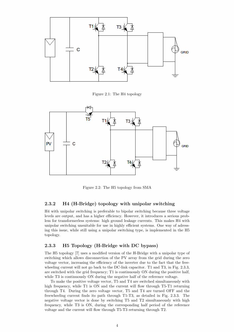
Figure 2.1: The H4 topology
Figure 2.2: The H5 topology from SMA
2.3.2 H4 (H-Bridge) topology with unipolar switching
H4 with unipolar switching is preferable to bipolar switching because three voltagelevels are output, and has a higher efficiency. However, it introduces a serious prob-lem for transformerless systems: high ground leakage currents. This makes H4 withunipolar switching unsuitable for use in highly efficient systems. One way of adress-ing this issue, while still using a unipolar switching type, is implemented in the H5topology.
2.3.3 H5 Topology (H-Bridge with DC bypass)
The H5 topology [7] uses a modified version of the H-Bridge with a unipolar type ofswitching which allows disconnection of the PV array from the grid during the zerovoltage vector, increasing the efficiency of the inverter due to the fact that the free-wheeling current will not go back to the DC-link capacitor. T1 and T3, in Fig. 2.3.3,are switched with the grid frequency; T1 is continuously ON during the positive half,while T3 is continuously ON during the negative half of the reference voltage.
To make the positive voltage vector, T5 and T4 are switched simultaneously withhigh frequency, while T1 is ON and the current will flow through T5-T1 returningthrough T4. During the zero voltage vector, T5 and T4 are turned OFF and thefreewheeling current finds its path through T1-T3, as detailed in Fig. 2.3.3. Thenegative voltage vector is done by switching T5 and T2 simultaneously with highfrequency, while T3 is ON, during the corresponding half period of the referencevoltage and the current will flow through T5-T3 returning through T2.
4
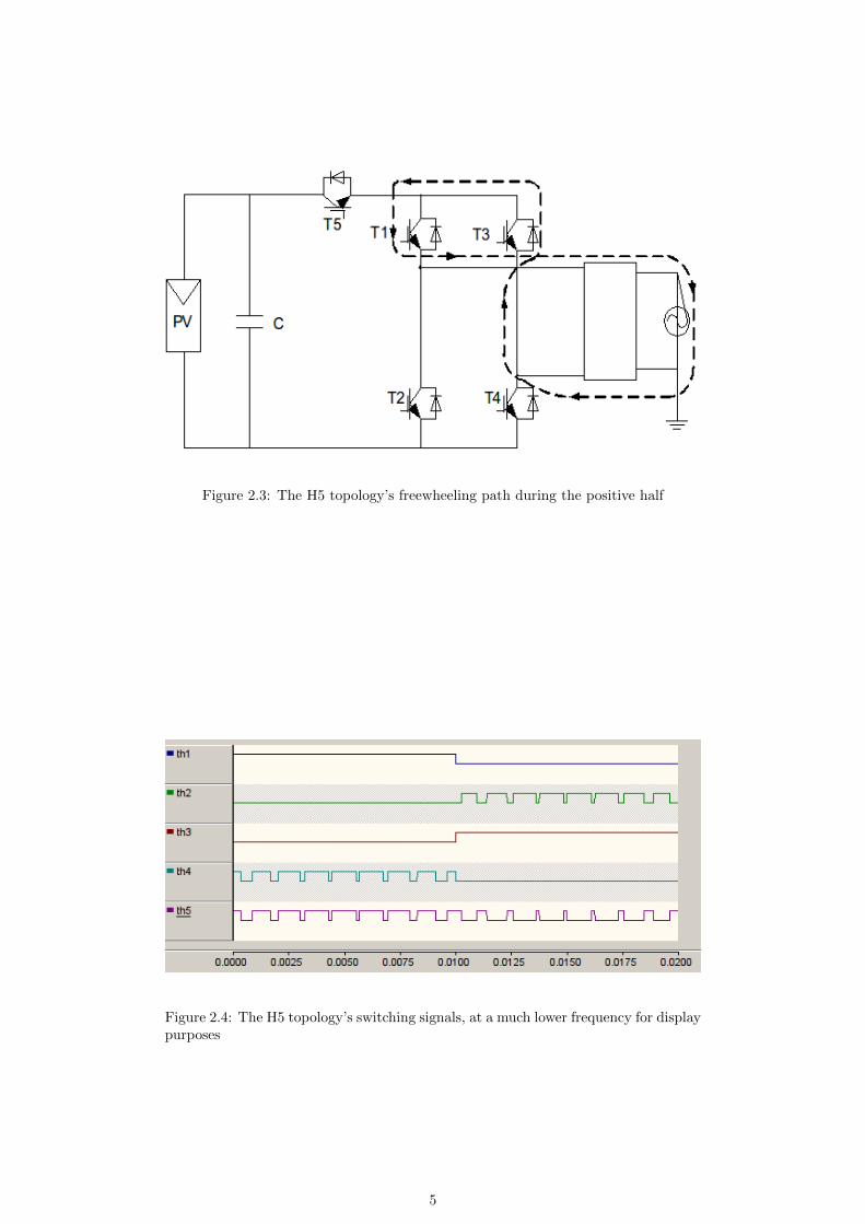
Figure 2.3: The H5 topology’s freewheeling path during the positive half
Figure 2.4: The H5 topology’s switching signals, at a much lower frequency for displaypurposes
5

A circuit for H5 was constructed in PSCAD, but correct output waveforms werenot obtained. The circuit and switching generation for H5 and H4 bi/unipolar isshown in Appendix A.
6

Chapter 3
Ground leakage current intransformerless topologies
A transformerless topology lacks the galvanic isolation between the PV array andgrid. This way the PV panels are directly connected to the grid, which means thatthere is a direct path for the leakage ground currents caused by the fluctuations ofthe potential between the PV array and the grid. These voltage fluctuations chargeand discharge the parasitic capacitance formed between the surface of the PV andgrounded frame, shown as CG−PV in Fig. 3. The effect of different values of CG−PV
and of a split or single inductor in the output filter was simulated, and can be seenin the following chapter.
The parasitic capacitance together with the DC line that connects the PV arrayto the inverter, form a resonant circuit and the resonance frequency of this circuitdepends on the size of the PV array and the length of the DC cables [2]. A study,presented in [10] discusses the electrical hazards when a person touches the surfaceof the PV array. Based on the inverter topology, PV panel structure and modulationstrategy, when touching the surface of the panels, a ground current could flow throughthe human body and if the current is above a certain levels it could lead to a shock orresulting in personal injury, as also discussed in [1]. The path of the ground current(IG-PV) flowing through the parasitic capacitance of the PV array is shown with anintermittent line in Fig. 3 In [10] several recommendations are given, which lead tothe minimization of the before mentioned leakage current, by:- grounding the frame of the PV array, which reduces the capacitance, thereby mini-mizing the ground leakage current.- carefully choosing the topology and the modulation strategy, thereby reducing thevoltage fluctuations between the PV array and ground.- disconnecting the inverter under service maintenance.
7
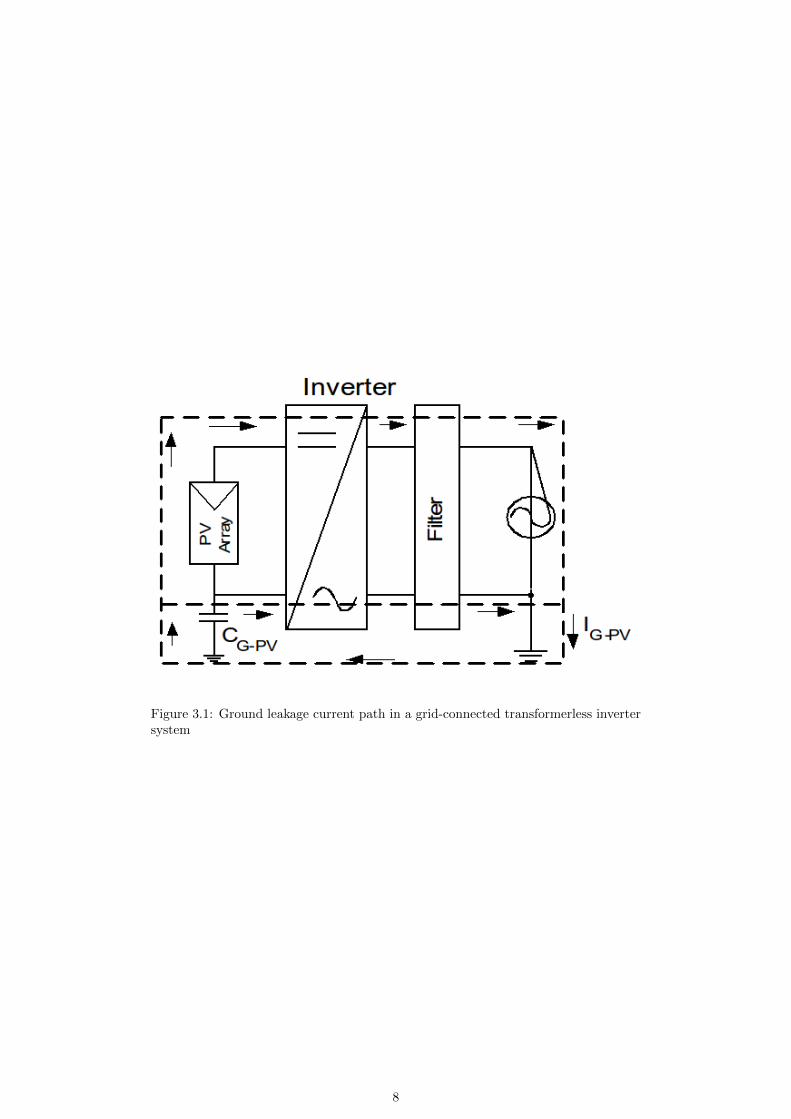
Figure 3.1: Ground leakage current path in a grid-connected transformerless invertersystem
8
Chapter 4
Simulations
All simulations were done on PSCAD, a time-step based simulator which solves dif-ferential equations.
4.1 Simulation settings
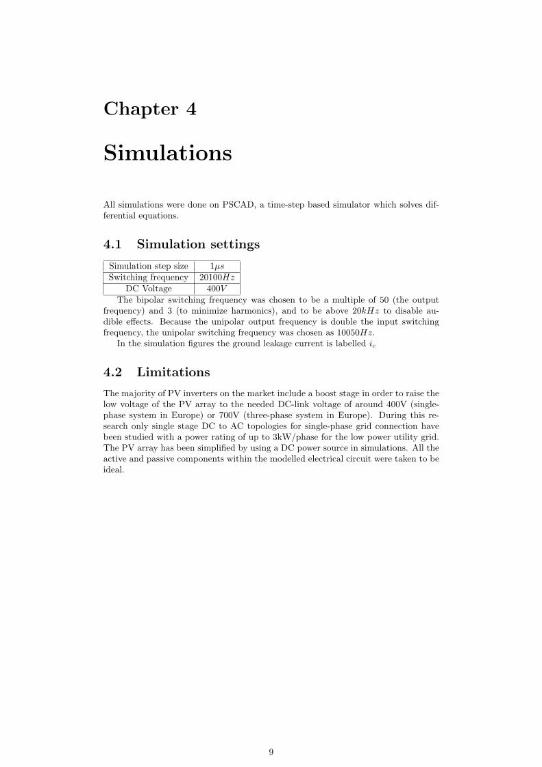
Simulation step size 1µsSwitching frequency 20100Hz
DC Voltage 400V
The bipolar switching frequency was chosen to be a multiple of 50 (the outputfrequency) and 3 (to minimize harmonics), and to be above 20kHz to disable au-dible effects. Because the unipolar output frequency is double the input switchingfrequency, the unipolar switching frequency was chosen as 10050Hz.
In the simulation figures the ground leakage current is labelled ic
4.2 Limitations
The majority of PV inverters on the market include a boost stage in order to raise thelow voltage of the PV array to the needed DC-link voltage of around 400V (single-phase system in Europe) or 700V (three-phase system in Europe). During this re-search only single stage DC to AC topologies for single-phase grid connection havebeen studied with a power rating of up to 3kW/phase for the low power utility grid.The PV array has been simplified by using a DC power source in simulations. All theactive and passive components within the modelled electrical circuit were taken to beideal.
9
4.3 Results
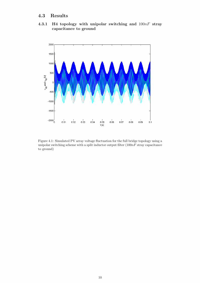
4.3.1 H4 topology with unipolar switching and 100nF straycapacitance to ground
Figure 4.1: Simulated PV array voltage fluctuation for the full bridge topology using aunipolar switching scheme with a split inductor output filter (100nF stray capacitanceto ground)
10
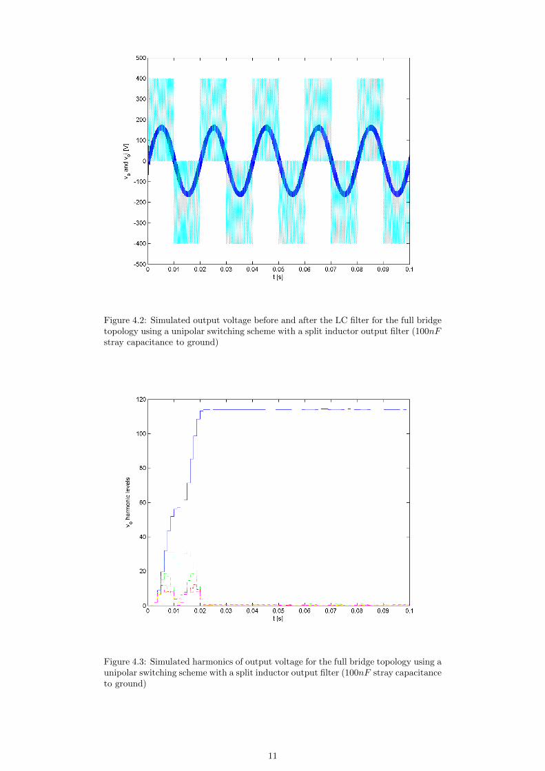
Figure 4.2: Simulated output voltage before and after the LC filter for the full bridgetopology using a unipolar switching scheme with a split inductor output filter (100nFstray capacitance to ground)
Figure 4.3: Simulated harmonics of output voltage for the full bridge topology using aunipolar switching scheme with a split inductor output filter (100nF stray capacitanceto ground)
11
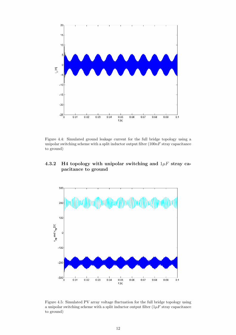
Figure 4.4: Simulated ground leakage current for the full bridge topology using aunipolar switching scheme with a split inductor output filter (100nF stray capacitanceto ground)
4.3.2 H4 topology with unipolar switching and 1µF stray ca-pacitance to ground
Figure 4.5: Simulated PV array voltage fluctuation for the full bridge topology usinga unipolar switching scheme with a split inductor output filter (1µF stray capacitanceto ground)
12
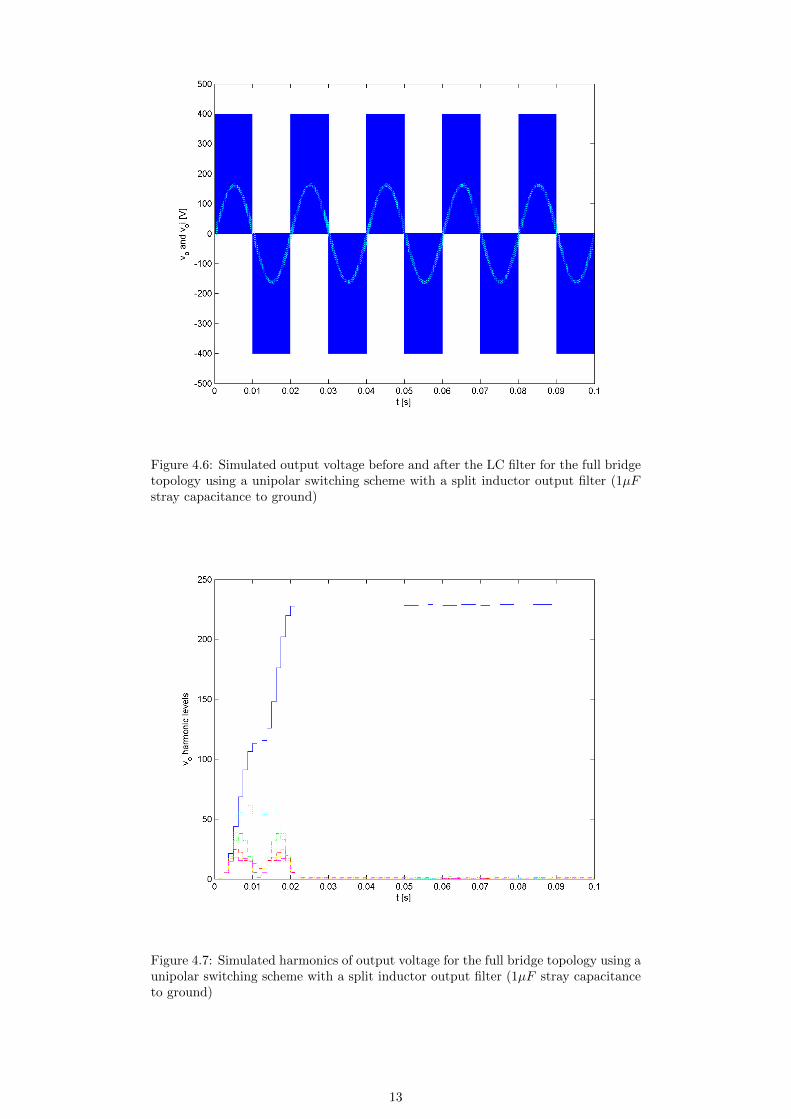
Figure 4.6: Simulated output voltage before and after the LC filter for the full bridgetopology using a unipolar switching scheme with a split inductor output filter (1µFstray capacitance to ground)
Figure 4.7: Simulated harmonics of output voltage for the full bridge topology using aunipolar switching scheme with a split inductor output filter (1µF stray capacitanceto ground)
13
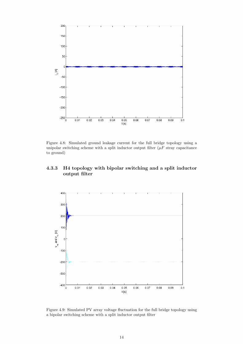
Figure 4.8: Simulated ground leakage current for the full bridge topology using aunipolar switching scheme with a split inductor output filter (µF stray capacitanceto ground)
4.3.3 H4 topology with bipolar switching and a split inductoroutput filter
Figure 4.9: Simulated PV array voltage fluctuation for the full bridge topology usinga bipolar switching scheme with a split inductor output filter
14
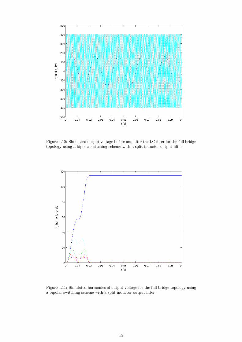
Figure 4.10: Simulated output voltage before and after the LC filter for the full bridgetopology using a bipolar switching scheme with a split inductor output filter
Figure 4.11: Simulated harmonics of output voltage for the full bridge topology usinga bipolar switching scheme with a split inductor output filter
15

Figure 4.12: Simulated ground leakage current for the full bridge topology using abipolar switching scheme with a split inductor output filter
4.3.4 H4 topology with bipolar switching and a single inductoroutput filter
Figure 4.13: Simulated PV array voltage fluctuation for the full bridge topology usinga bipolar switching scheme with a single inductor output filter
16
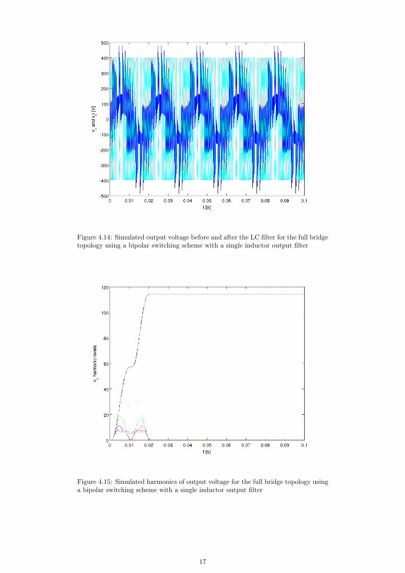
Figure 4.14: Simulated output voltage before and after the LC filter for the full bridgetopology using a bipolar switching scheme with a single inductor output filter
Figure 4.15: Simulated harmonics of output voltage for the full bridge topology usinga bipolar switching scheme with a single inductor output filter
17

Figure 4.16: Simulated ground leakage current for the full bridge topology using abipolar switching scheme with a single inductor output filter
18
Chapter 5
Conclusion
The H4 topology serves as a useful base for more complex topologies which resultin greater efficiencies. These topologies overcome issues of safety and efficiency byisolating the DC source from the grid during the zero current vector and greatlyminimizes the ground current leakage caused by the PV frame’s stray capacitance.We would advise the introduction of the simulation package earlier in the course. Theinterface, and simulation in general, takes time to learn. That takes time away fromgrasping the learning opportunities offered during the project.
19
Bibliography
[1] Eisner Safety Consultants. Leakage current part 1.
[2] O. Lopez R. Teodorescu J. Doval-Gandoy. Multilevel transformerless topologiesfor single-phase grid-connected converters. IEEE 32nd Annual Conference onIndustrial Electronics, pages 5191–5196, 2006.
[3] T. Ishikawa. Grid connected photovoltaic power systems: Survey of inverter andrelated protection equipments. Technical report, IEA PVPS T5-05, 2002, 2006.
[4] S. Rollier B. Richard M. Keller. Earth leakage control in solar inverters. PowerSystem Design Europe, 2005.
[5] F.Blaabjerg R.Teodorescu Z.Chen M. Liserre. Power converters and control ofrenewable energy systems. Proc. ICPE, 2004.
[6] Rym Marouani Abdelkader Mami. Voltage oriented control applied to a gridconnected photovoltaic system with maximum power point tracking technique.American Journal of Applied Sciences, 7, 2010.
[7] R. Gonzalez J. Lopez P. Sanchis L. Marroyo. Transformerless inverter for single-phase photovoltaic systems. EEE Trans. Power Electron., 22:693–697, March2007.
[8] Ned Mohan Tore M. Undeland William P. Robbins. Power Electronics: Con-verters, Applications, and Design. Wiley; 3 edition, 2002.
[9] L. Gertmar P. Karlsson O. Samuelsson. On dc injection to ac grids from dis-tributed generation. 11th European Conference on Power Electronics and Appli-cations, 2005.
[10] H. Schmidt B. Burger Chr. Siedle. Gefahrdungspotenzial transformatorloserwechselrichter - fakten und geruchte. Symposium Photovoltaische Sonnenenergie,pages 89–98, 2003.
[11] Larry West. Global investment in renewable energy sets record of us30 billion.
20

Appendix A
PSCAD circuits
Figure A.1: H4 unipolar
21
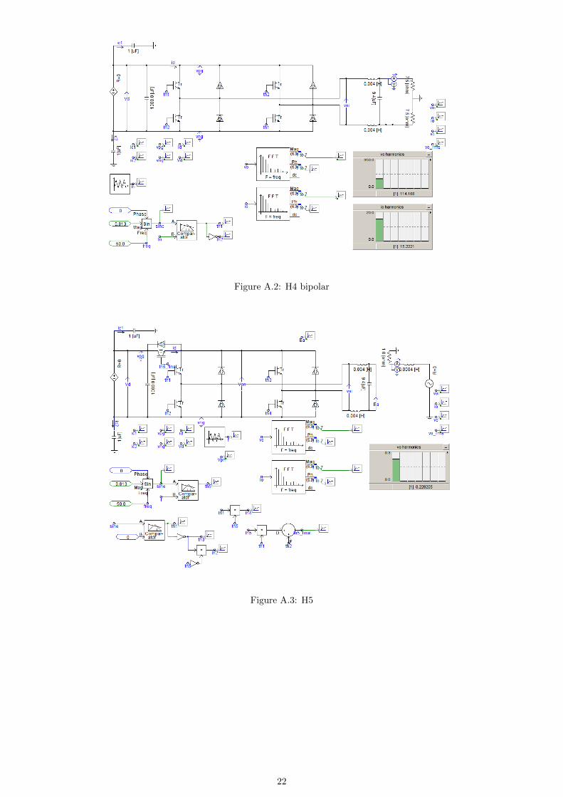
Figure A.2: H4 bipolar
Figure A.3: H5
22