power electronic interfaces for solar pv - silicon institute...
TRANSCRIPT

Power Electronic Interfaces for Solar PV
SIT
Bhubaneswar
19-2-2015
Aby Joseph
Power Electronics Group
CDAC
Thiruvananthapuram
2/23/2015 1 CDAC-All rights reserved

Motivation
Centralized generation facilities are giving way to small, green,
distributed generators due to many reasons
Distributed generators impose many challenges associated with
operation, control and protection
Distributed generators and loads in the neighborhood can form
microgrids which can work parallel to grid or operate in islanded
mode providing UPS services
The Microgrid can be assumed as a cluster of loads and micro-
sources operating as a single controllable system that provides
power to its local area
Microgrid technology will enhance the distributed architecture of
power networks
Off grid Microgrid architecture which can go to ON grid mode
Remote OFF grid mode
2/23/2015 2 CDAC-All rights reserved

Microgrid(Contd.)
PCU 1
PCU 2
PCU n
Load 1 Load 2 Load n
Utility Grid
Synchronising Switch
PCU n
Import/Export metering
AC Grid
2/23/2015 3 CDAC-All rights reserved
Advantages
• Standby / Backup power to improve the availability and
reliability of electric power
• Peak load shaving
• Sales of power back to utilities or other users
• Free energy input, zero operational costs (except diesel
gensets), minimal maintenance
• Power quality, such as reactive power compensation and
voltage support
• Reduction in environmental pollution
• Reduction of distribution losses in the grid.
2/23/2015 4 CDAC-All rights reserved

Standards
• IEEE 1547 Series standards for interconnection of distributed sources with
electric power system (IEEE 1547.4-2011 specifically for design, operation
and integration of DRs with microgrids)
• IEEE 1547.3- 2007 (On communication protocols)
• IEEE 519-1992(Power Quality)
• IEC 61850-7-420(Communication for microgrids)
2/23/2015 5 CDAC-All rights reserved

Inverter 1
Inverter 2
Inverter 3
Charge Controller 1
Charge Controller 2
WIND ELECTRIC
GENERATOR
(5 kW)
Battery Bank 2
Battery Bank 1
Feeder 1
Wind
Turbine
Controller
BS1
BS2
S1
S2
S3
S4
S5
S6
Feeder 2
S10
S8
CS2
CS1
CS4
CS3
S11
Original System
55 kWp
20 kW
25 kW
25 kW
25 kW
240V, 600Ah
240V, 600Ah 2/23/2015 6 CDAC-All rights reserved

Location
2/23/2015 7 CDAC-All rights reserved

Comparison
Original System
• Power conditioning systems from
various vendors(solar charge
controller, WEG interface,
inverters)
• Frequent failures
• Lack of modularity
• Maintenance and service
New System
• Interface to common AC link which
also acts as a feeder
• Modular hardware for seamless
integration
• Central controller for co-ordination
• Betterment of protection schemes
Gen 1
Gen n
Charge Controller 1
Charge Controller n
Battery Bank
Inverter
Load
Gen 1
Gen n
Load
CCU
AC Bus
(Central loads)
2/23/2015 8 CDAC-All rights reserved

2/23/2015 9 CDAC-All rights reserved

Newly Installed System
BIM
BIM
BIM
BIM
BIO-MASS
WIND GENERATOR
BIM – Basic Power Electronics
Interface Module
SOLAR PHOTOVOLTAIC ARRAY
BATTERY BANK
Y MICRO-GRID
CO
NS
UM
ER
L
OA
DS
Y
Y
Y
CCU 2/23/2015 10 CDAC-All rights reserved

BIM 7
BIM 8
BIM 9
BIM 1
BIM 2
BIM 3
BIM 4
BIM 5
BIM 6
Digital Controller 1
Central
Control
unit
Digital Controller 2
Digital Controller 3
SOLAR PANEL
(55 kWp)
WIND ELECTRIC
GENERATOR
(5 kW)
BIO-MASS PLANT (20 kW)
BIM - Basic Interface Module (10 kVA)
Panel 1
Panel 2
Panel 3
Y
Dump Load
Y
Y
Y
Y
Y
Y
Y
Y
2/23/2015 11 CDAC-All rights reserved
Challenges
• Optimum power extraction from the renewable sources.
• Power flow management (Active and reactive)
• Monitoring of thermal performance of circuit elements.
• Communication between individual blocks of the system
and the central control unit.
• Control during short circuits
• Maintenance of synchronism of the micro grid during grid
interactive operation
• Control during the islanding events
2/23/2015 12 CDAC-All rights reserved

Power hardware Requirement
Unregulated DC
Regulated AC
Unregulated AC
Regulated AC
Solar Photovoltaics
WEG, Microhydel, DG
BIM
N
A
B
C
U
V
W Feeder
Interface
Magnetics
BIM
U
V
W Feeder
2/23/2015 13 CDAC-All rights reserved

Basic Interface Module
A
B
C
U
V
W
P
N
2/23/2015 14 CDAC-All rights reserved
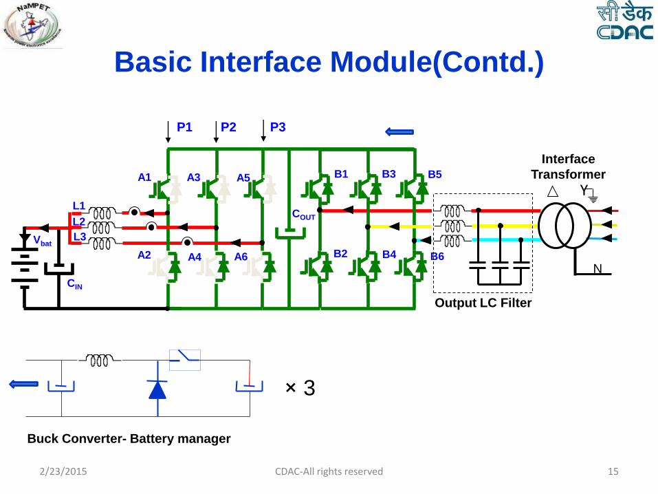
Basic Interface Module(Contd.)
L1
L2
L3
A1
A2
A3
A4
A5
A6
B1
B2
B3
B4
B5
B6
Output LC Filter
COUT
CIN
Interface
Transformer
Vbat
P1 P2 P3
Y
× 3
Buck Converter- Battery manager
N
2/23/2015 15 CDAC-All rights reserved

Basic Interface Module(Contd.)
L1
L2
L3
A1
A2
A3
A4
A5
A6
B1
B2
B3
B4
B5
B6
Output LC Filter
COUT
CIN
Interface
Transformer
P1 P2 P3
Y
N
Solar PV or Battery
× 3
Boost Converter- Battery manager &
Solar PV Interface
2/23/2015 16 CDAC-All rights reserved

Basic Interface Module(Contd.)
L1
L2
L3
A1
A2
A3
A4
A5
A6
B1
B2
B3
B4
B5
B6
Output LC Filter
COUT
CIN
Interface
Transformer
P1 P2 P3
Y
N
L1 L2
C
IGBT Inverter
2/23/2015 17 CDAC-All rights reserved

Basic Interface Module(Contd.)
Half bridge IGBT Module 3-Phase Full Bridge IGBT Module 3-Phase Full Bridge IPM
2/23/2015 18 CDAC-All rights reserved

Basic Interface Module(Contd.)
GATE DRIVER INTERFACE
CIRCUIT 1 GATE DRIVER INTERFACE
CIRCUIT 2
CONV 2
COOLING FAN COOLING FAN HEAT SINK
CONV 1
Rated power 10 kVA
DC Bus voltage 400V Max
AC Voltage 200V l-n nominal,
3 phase, 50 Hz,
droop on
overload
Output power
factor(Grid Side)
0.8 nominal,
load determined
Ambient Temp 50o C max
Switching
frequency
5 kHz
Switching
devices
IGBT/IPM
Protections SC, DC O/V,
Overload, over
temp.
DC Bus
construction
with low
inductance
sandwich bus
Cooling System Forced air
cooling
Specification
2/23/2015 19 CDAC-All rights reserved

Power Hardware Design • Selection of Switching Device Input Voltage
(Solar Photovoltaic VOC=400V, Vmpp = 320V Battery nominal voltage = 240V)
WEG = 48V, DC
Bus Voltage : 400V DC
Output Voltage : 200V(L-L rms)
Selected Switching device : PM150CLA060 – 600V, 150A IPM Module(6 pack)
• Thermal Design
Required thermal resistance of the hetsink = 0.08575 0C/W
Air velocity : 6m/s
Simulation tools : Melcosim & Flowtherm 2/23/2015 20 CDAC-All rights reserved

Construction of BIM
Switching Device
Gate interface card
DC Bus capacitor
Heatsink & fan
Thermostat for OT protection
Sandwich bus interconnections 2/23/2015 21 CDAC-All rights reserved
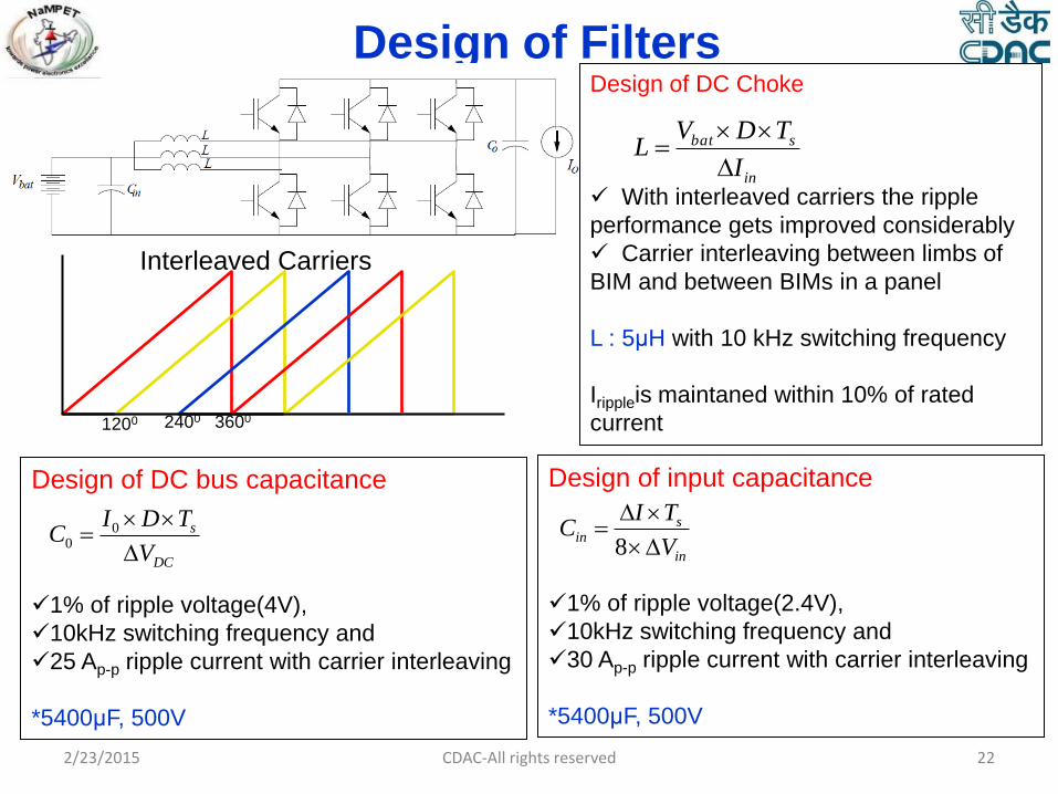
Design of Filters Design of DC Choke
With interleaved carriers the ripple
performance gets improved considerably
Carrier interleaving between limbs of
BIM and between BIMs in a panel
L : 5μH with 10 kHz switching frequency
Irippleis maintaned within 10% of rated
current
Interleaved Carriers
2400 1200 3600
in
sbat
I
TDVL
Design of DC bus capacitance
1% of ripple voltage(4V),
10kHz switching frequency and
25 Ap-p ripple current with carrier interleaving
*5400μF, 500V
DC
s
V
TDIC
0
0
Design of input capacitance
1% of ripple voltage(2.4V),
10kHz switching frequency and
30 Ap-p ripple current with carrier interleaving
*5400μF, 500V
in
sin
V
TIC
8
2/23/2015 22 CDAC-All rights reserved

Design of Filters(Contd.) LC filter is used to filter out the high
frequency harmonics on top of the
fundamental component of inverter
output voltage
LC, being a second order filter provides
better attenuation for high frequency than the
first order filter with same bandwidth
By nature an undamped system since no
external resistance is included (*active
damping)
L&C values to be picked based on filtering
requirement, availability and economics
1)(
1
)(
)(2
sRRsCL
sCR
sV
sV
fcff
fC
i
O
The filter shall provide attenuation of 30dB
or more for frequencies above switching
Frequencies.
For 5kHz switching frequency
Lf =680μH & Cf = 47μF (Corner frequency 890 Hz)
For 10kHz switching frequency
Lf =540μH & Cf = 47μF (corner frequency 1000Hz)
0
2log4030
sf
2/23/2015 23 CDAC-All rights reserved

Back to Back
Inverter
Module
with IPMs
Output Filter Output CT
Module Interface
Transformer
Load Side
Contactor Load side
MCB
DIGITAL CONTROLLER
(DSP+FPGA)
INV 2 INV 1
RINV 1
YINV 1
BINV 1
NBINV 1
RINV 1
YINV 1
BINV 1
NBINV 1
RINV 2
YINV 2
BINV 2
Cooling Fan Cooling Fan
From Current/Voltage
/Temperature
Sensors
Auxiliary
Control Signal Communication
Display/
User Interface
RINV 2
YINV 2
BINV 2
Lo
ad
Sid
e
Inductor
Module Source Side
Contactor Source side
MCB
So
urc
e S
ide
(DC
)
2/23/2015 24 CDAC-All rights reserved

2/23/2015 25 CDAC-All rights reserved

Testing
2/23/2015 26 CDAC-All rights reserved
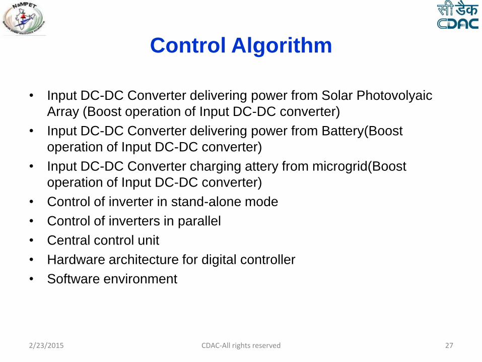
Control Algorithm
• Input DC-DC Converter delivering power from Solar Photovolyaic
Array (Boost operation of Input DC-DC converter)
• Input DC-DC Converter delivering power from Battery(Boost
operation of Input DC-DC converter)
• Input DC-DC Converter charging attery from microgrid(Boost
operation of Input DC-DC converter)
• Control of inverter in stand-alone mode
• Control of inverters in parallel
• Central control unit
• Hardware architecture for digital controller
• Software environment
2/23/2015 27 CDAC-All rights reserved

Solar Cell Model
2/23/2015 CDAC-All rights reserved 28
Practical PV cell
Rp
Ipv
29
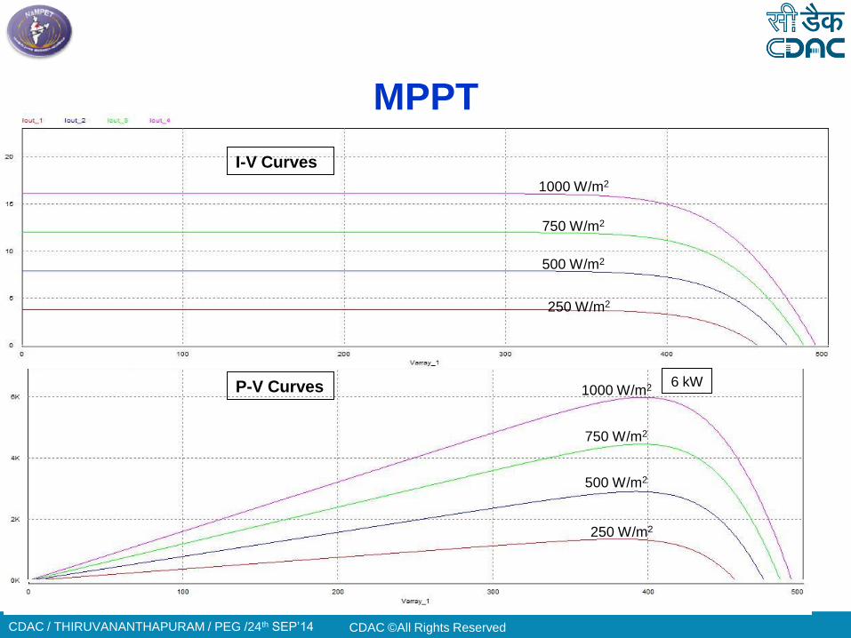
MPPT
CDAC ©All Rights Reserved CDAC / THIRUVANANTHAPURAM / PEG /24th SEP’14
250 W/m2
500 W/m2
750 W/m2
1000 W/m2
250 W/m2
500 W/m2
750 W/m2
1000 W/m2
I-V Curves
P-V Curves 6 kW
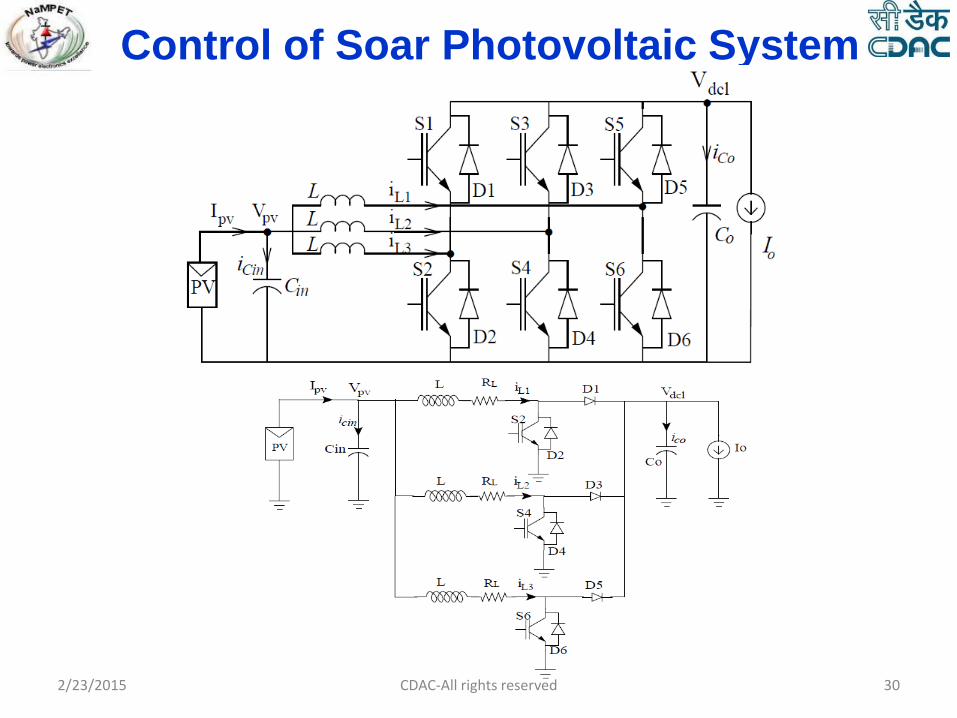
Control of Soar Photovoltaic System
2/23/2015 30 CDAC-All rights reserved

L
O
A
D
Vdcl
Vpv
Vdcl* +
- HV
Current Control PDCPM
Current Control PDCPM
Current Control PDCPM
Vdcl
d1
d2
d3
d1 d2 d3
Cin
Co
Control of Soar Photovoltaic System
2/23/2015 31 CDAC-All rights reserved
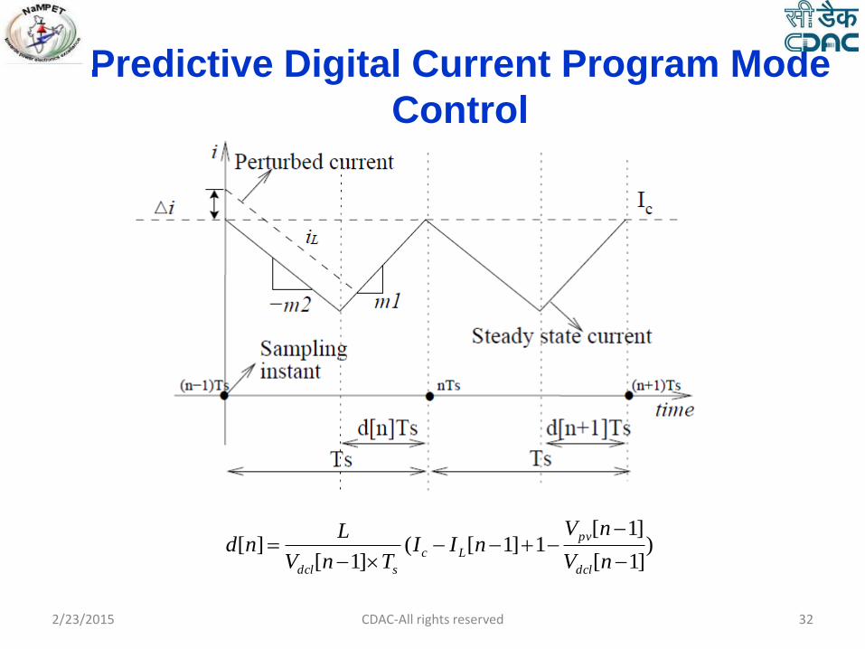
Predictive Digital Current Program Mode
Control
)]1[
]1[1]1[(
]1[][
nV
nVnII
TnV
Lnd
dcl
pv
Lc
sdcl
2/23/2015 32 CDAC-All rights reserved

Control of Battery Management System
Charging – Buck mode
)]1[
]1[1])1[(
]1[][
nV
nVnII
TnV
Lnd
dc
batLc
sdc
)]1[
]1[])1[(
]1[][
nV
nVnII
TnV
Lnd
dc
batLc
sdc
Discharging – Boost mode
Constant Current charging
Constant Voltage charging
State of charge estimation
MPPT control of solar photovoltaics 2/23/2015 33 CDAC-All rights reserved

Waveforms
TT
TT
1) Ch 1: 2 Volt 5 ms
2) Ref A: 1 Volt 10 ms
2/23/2015 34 CDAC-All rights reserved

Control of Inverters Control in the stand alone mode
IGBT Inverter
L1
L2
C
R1 L1
C
Vo Vi
11
1
RsL
ii ic
ic
io
Cs
1+ -
Vi Vc Ii
Io
Ic +
- )(sH
+
M 11
1
RsL Cs
1+ -
Ii
Io
Ic
VCRef VC
Vp
Kd
Vp* Vi
Control blocks in αand β frames
PR Controller
Vc
+ -
- +
-
2/23/2015 35 CDAC-All rights reserved
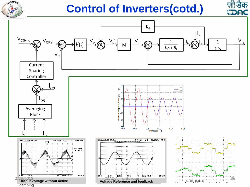
Control of Inverters(cotd.)
+ - )(sH
+
M 11
1
RsL Cs
1+ -
Ii
Io
Ic
VC
Vp
Kd
Vp* Vi
VCRef
Averaging Block
In I1
Ion*
- + - VC
- + Ion
Current Sharing
Controller
+ +
VCSync
Output voltage without active
damping Voltage Reference and feedback
2/23/2015 36 CDAC-All rights reserved
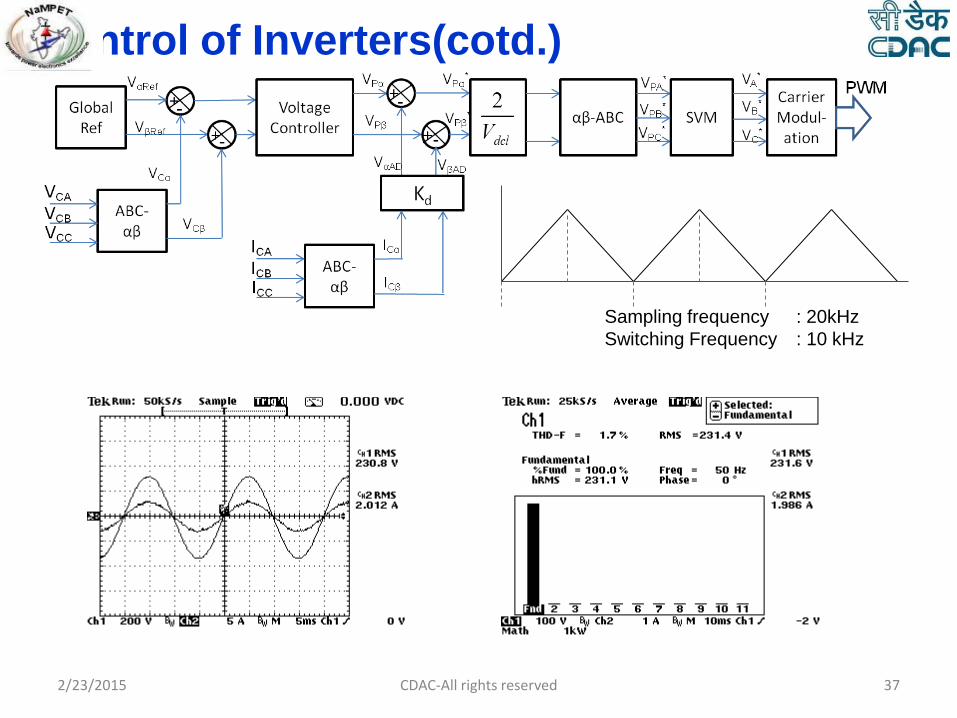
Control of Inverters(cotd.)
Sampling frequency : 20kHz
Switching Frequency : 10 kHz
2/23/2015 37 CDAC-All rights reserved

Digital Controller Hardware
Controller Requirement
PWM Ports : 6 Sets
ADC Channels : 33
FPGA for resource enhancement and data processing
e-can network for data exchange
Key pad and graphic LCD interface
Memory
I/O ports
DSP1 -Master processor for control of the power electronic converters
DSP2 –Supervisory controller
FPGA
2/23/2015 38 CDAC-All rights reserved

Digital Controller Hardware(contd.)
FPGA
I/O Ports
PWM Interface(6X6)
Data Bus
DSP1 (TMS320F2812)
SPI
…. ADC 1 ADC 4
PWM
interface
2x6
DSP2 (TMS320F2812)
eCAN
SPI
eCAN Driver
Touch
Screen
Controller
LCD Interface
I/O Ports
I/P Ports
(3 Nos) to select
application
Battery
Back Up RAM
I/O ports
FAULT
2/23/2015 39 CDAC-All rights reserved

Digital Controller Hardware(contd.) Digital Signal Processor
(TMS320F2812)
High performance 32 bit CPU
150 MHz (6.67 ns cycle time)
Low-Power (1.8-V Core @135 MHz, 1.9-V Core @150 MHz, 3.3-V I/O) Design
176-Pin Low-profile Quad Flat Pack (LQFP)
Two Event Managers
12-Bit ADC, 16 Channels
Three 32-Bit CPU-Timers
Three External Interrupts
128-Bit Security Key/Lock
External Memory Interface up to 1M total memory
FPGA
( Cyclone II EP2C5Q208C8)
High-density architecture with 4,608 logic elements
13 Embedded multipliers & 26 x 4K Memory Blocks
Advanced I/O support
8 Nos of Clock pins up to 250 MHz Performance
2 PLLs & 158 maximum User I/O Pins
Package: 208 pin PQFP (Plastic Quad Flat Pack)
2/23/2015 40 CDAC-All rights reserved

Digital Controller Hardware(contd.)
External ADC
Interface
(32 Channels)
FPGA
DSP s(TMS320F2812PGFA)
Internal ADC
Interface
(16 Channels)
Input Ports
Output Port
Internal
PWMs
Power Supply
PWM
Interface
2/23/2015 41 CDAC-All rights reserved

2/23/2015 42 CDAC-All rights reserved

Scheme-Grid Interactive Power Converter
2/23/2015 CDAC-All rights reserved 43
Y
Solar Photovoltaic
Array
POWER CONDITIONING UNIT
Utility Grid
Three phase
Inverter
Interface
Transformer
Digital Controller
Remote Data-
logging unit

44
BIM 1
Digital Controller (DSP + FPGA)
SOLAR PV ARRAY
(25 kWp)
Y
Y
Y
BIM 2
BIM 3
DCF 1 ACF 1 Tr 1
Grid
DCF
2
DCF 3
ACF 2
ACF
3
Tr 2
Tr 3
= =
= ~
BIM – Basic Interface Module
DCF – DC filter
ACF - AC filter
Tr 1-Tr 3 – Interface transformers
PCU PANEL
2/23/2015 CDAC-All rights reserved
Scheme-Grid Interactive Power Plant

45
Inverter Configurations available
Topology 1 – with Split DC Link capacitors
Topology 2 – with Four leg inverter
Topology 3 – with Three leg inverter +
coupling transformer
2/23/2015 CDAC-All rights reserved

46
Grid /
Load
Drawbacks
• DC Bus voltage equalization
• Zero sequence current handling
• control complexities
• No Isolation 2/23/2015 CDAC-All rights reserved
Topology -1
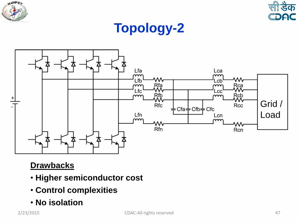
47
Grid /
Load
Drawbacks
• Higher semiconductor cost
• Control complexities
• No isolation 2/23/2015 CDAC-All rights reserved
Topology-2

48
Grid /
Load
Advantages
• Low voltage power electronics module
• Limits inrush currents
• Limits DC injection current
• Leakage inductance acts as filter inductor
• Local expertise available 2/23/2015 CDAC-All rights reserved
Topology 3

49
Solar PV System(Boost mode)
L1
L2
L3
S1
S2
S3
S4
S5
S6
S11
S21
S31
S41
S51
S61
Output LC Filter
COUT
CIN
Interface
Transforme
r
Micro-Grid
PWM
GENERATION
PDCPM 1
PDCPM 2
PDCPM 3
Voltage
Controller
(PI)
Ic
d1
d2
d3
Vref
Inner Current Control Loop
IL1
IL2
IL3
PDCPM - Predictive Digital Current
Program Mode
MPPT - Maximum Power Point
Tracking
P2
P4
P6 DSP
FPGA
MPPT
Controller VPV
Solar PV
P2 P4 P6
Vpv Ipv
Y
e(t)
Exporting Power
2/23/2015 CDAC-All rights reserved

Control algorithm
CDAC-All rights reserved 50 2/23/2015

Control algorithm(contd.)
CDAC-All rights reserved 51 2/23/2015
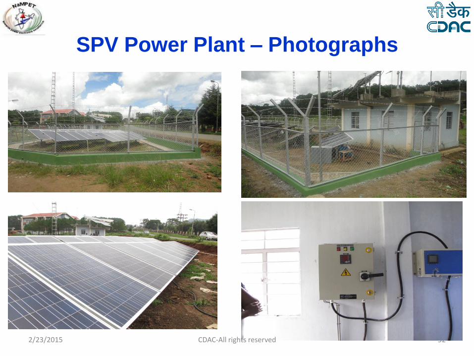
52 2/23/2015 CDAC-All rights reserved
SPV Power Plant – Photographs

53 2/23/2015 CDAC-All rights reserved
Photographs – installed at NEHU

54
THD(IR)
VRN versus IR
2/23/2015 CDAC-All rights reserved
Test Waveforms

55 2/23/2015 CDAC-All rights reserved
Test Waveforms

56
Voltage and Current waveforms at various power levels
Power : 2.2 kW Power : 8.5 kW Power : 15.5 kW
V I
V I V I
2/23/2015 CDAC-All rights reserved
Test Waveforms

MW Level Power Plant
Design, develop and demonstrate the Power Conversion Systems for
Grid Connected Solar Photovoltaic Power Plants with a cumulative
rating of 1MW, aiming Indian market. The development will focus on
following features
• Capability to ride through faulty and disturbed grid conditions
• Voltage stabilization by reactive power support
• Improved Power Quality
• Stiff control over active power like in conventional rotary generators
• Improved efficiency
• Improved reliability
• Better Modularity and Maintainability
• Operational redundancy
• Communication features and controllability
57 CDAC-All rights reserved 2/23/2015

MW Level Power Plants
Solar PV Array
Power Conditioning Unit
Interconnecting Transformer
Grid
Output Voltage Sensing
Power Converter
Line Filter
Converter Control
Input SFU
Solar PV Array
Input Contactor
Input Current Sensing
Input Voltage Sensing
Output Current Sensing
Output SFU
Output Contactor
Transformer
Power Conditioning Unit (PCU)
Utility grid
CDAC-All rights reserved 58 2/23/2015

System Rating
1.32 MVA(1 MW) is achieved using 4 PCUs with individual rating of 330
kVA (250kW)
Each 330 kVA has 3 inverter stacks working in parallel each handling 110
kVA
Each inverter stack assembled on a single heatsink
Each PCU has an interconnecting transformer for attenuating DC
components in current and for voltage matching
The impedance of the interconnecting transformer adds to the grid side
impedance for the LCL filter
3 Phase
Inv. Stack
Grid
59 CDAC-All rights reserved 2/23/2015

Scheme of complete system
CDAC-All rights reserved 60 2/23/2015

Supervisory Control
CDAC-All rights reserved 61
Ethernet Link
Supervisory Control station
PCU-1 PCU-2 PCU-3 PCU-4
monitoring
Alarm
Relay control
Data logging
2/23/2015
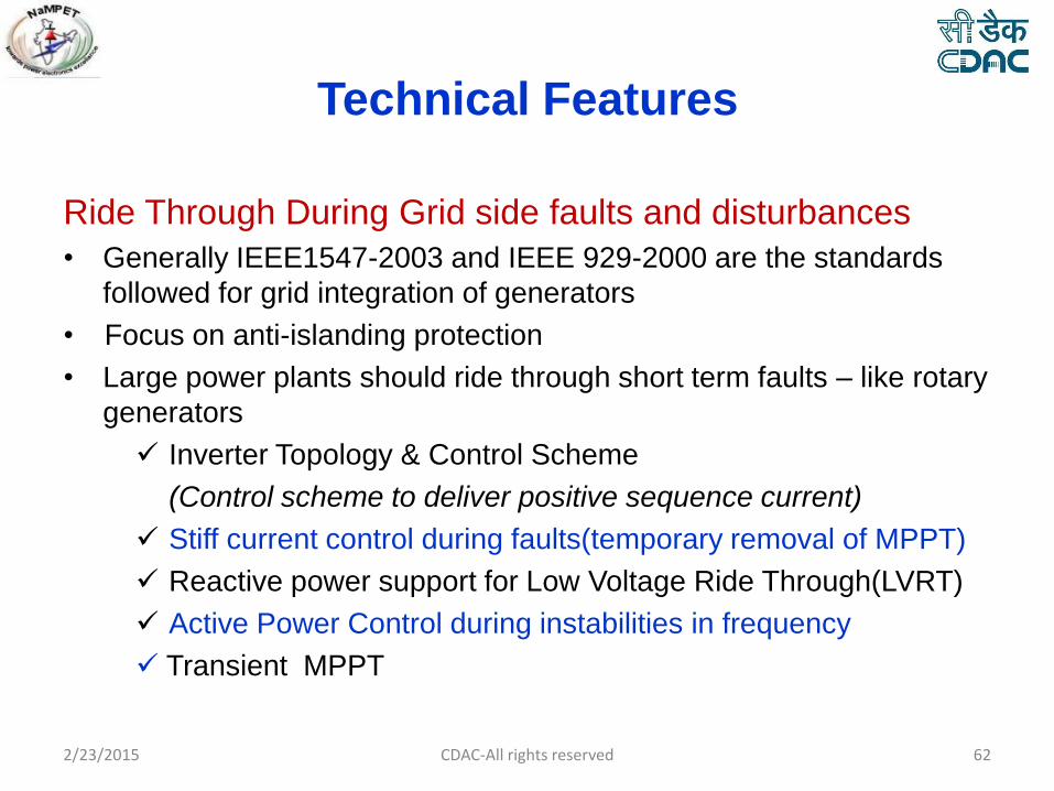
Technical Features
Ride Through During Grid side faults and disturbances
• Generally IEEE1547-2003 and IEEE 929-2000 are the standards
followed for grid integration of generators
• Focus on anti-islanding protection
• Large power plants should ride through short term faults – like rotary
generators
Inverter Topology & Control Scheme
(Control scheme to deliver positive sequence current)
Stiff current control during faults(temporary removal of MPPT)
Reactive power support for Low Voltage Ride Through(LVRT)
Active Power Control during instabilities in frequency
Transient MPPT
CDAC-All rights reserved 62 2/23/2015
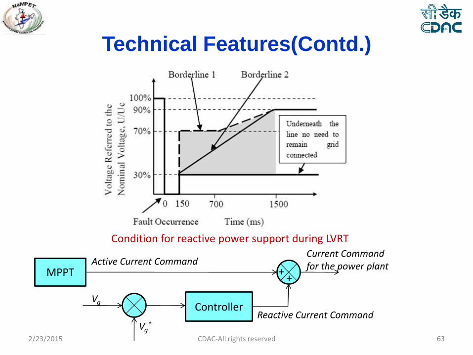
Technical Features(Contd.)
Condition for reactive power support during LVRT
MPPT Active Current Command
Vg
Vg*
Controller
Current Command for the power plant
+ +
Reactive Current Command
CDAC-All rights reserved 63 2/23/2015

Technical Features(Contd.)
Efficiency & Redundancy Variable structure PWM which integrates Space Vector Modulated PWM
and Discontinuous PWM will be used for switching of the inverters. This will
help in managing both efficiency and current TDD optimally. The efficiency
improvement by this is estimated as 3%
Variable switching frequency based on power levels to reduce losses at
higher power levels
Sleep mode with reduced standby power (<0.25%)
MPPT for better conversion efficiency
Selection of low loss devices
Efficient sequencing of parallel modules according to power level
CDAC-All rights reserved 64 2/23/2015

Technical Features(Contd.)
Redundancy & Reliability • Paralleled power modules
• Optimum thermal design to keep the junction temperature of switching
devices to provide life expectancy better than15 years
• Design of DC capacitor bank to achieve better reliability. The design will be
done with film capacitors with better life & large ripple current capacity
• Critical design of subsystems and auxiliary electronics circuit to achieve
better reliability
• Over temperature protection
• Lightning and surge protection
• Instantaneous hardware over current and over voltage protections
• On-line diagnostics algorithm to find out the health of critical components in
the power plant(Electrolytic capacitor, switching device and gate drive
circuits)
CDAC-All rights reserved 65 2/23/2015
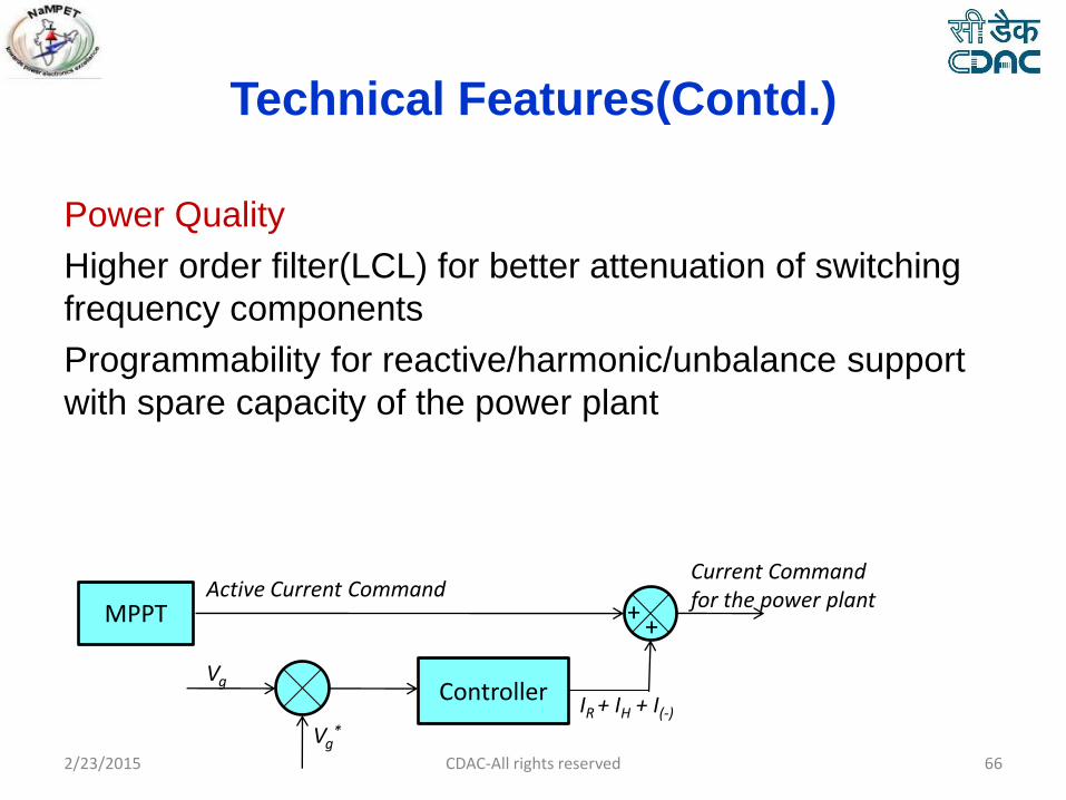
Technical Features(Contd.)
Power Quality
Higher order filter(LCL) for better attenuation of switching
frequency components
Programmability for reactive/harmonic/unbalance support
with spare capacity of the power plant
MPPT Active Current Command
Vg
Vg*
Controller
Current Command for the power plant
+ +
IR + IH + I(-)
CDAC-All rights reserved 66 2/23/2015

Technical Features(Contd.)
Protections • Input DC overvoltage protection
• Input over current protection
• Output over current protection
• Earth faults
• Grid side over voltage/under voltage protection
• Frequency error protection
• Protection during single phasing
• Over temperature protection for the converter
• Anti Islanding protection during grid failure and sustained grid faults
Modular design
Remote Programmability
CDAC-All rights reserved 67 2/23/2015

Supervisory Control(contd)
CDAC-All rights reserved 68
HMI
Communicatio
n PCB
Bluetooth link
Android Tablet
As Display Server
User
Solar Power Conditioning Unit
Serial Link
2/23/2015
Thank You
2/23/2015 69 CDAC-All rights reserved

2/23/2015 CDAC-All rights reserved 70