power electronics no. 15: three-phase inverter ii takeshi...
TRANSCRIPT

1
Power Electronics No. 15: Three-phase Inverter II
Takeshi Furuhashi Furuhashi_at_cse.nagoya-u.ac.jp

Three Pulse PWM
2
If vcomu > vtri Tr1 ON,Tr2 OFF If vcomu < vtri Tr1 OFF,Tr2 ON
If vcomw > vtri Tr5 ON,Tr6 OFF If vcomw < vtri Tr5 OFF,Tr6 ON
If vcomv > vtri Tr3 ON,Tr4 OFF If vcomv < vtri Tr3 OFF,Tr4 ON
-1 -0.5
0.5 1
5 6 6 5 5 6
1 2 1 1 2 2
3 4 4 3 3 4
vcomv vcomw vtri vcomu
vvw
vwu
vuv
0
VE
0
VE
0
VE
0
-VE
VE
0
-VE
VE
0
-VE
VE
vv
vw
vu
t
t
t
t
t
t
t
vuv=vu - vv
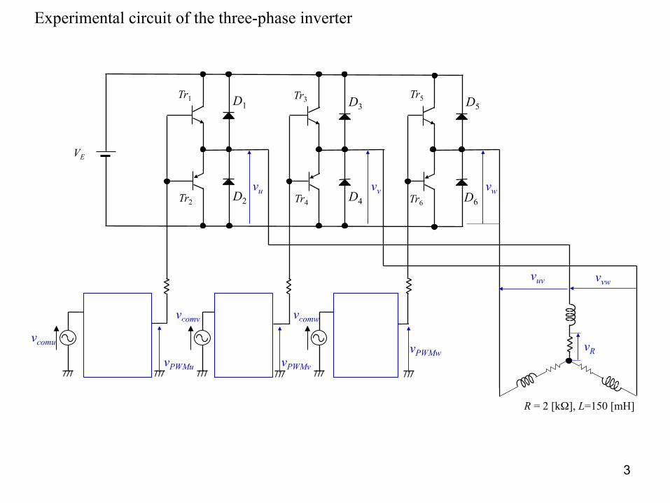
Experimental circuit of the three-phase inverter
vtri
vcomv
vPWMu
- - vPWMw -
VE
D6 Tr4 D4 Tr6 Tr2 D2
D1 Tr1 D5 D3
Tr3 Tr5
vPWMv
vcomw
vcomu
+ + +
vw vu vv
vvw vuv
vR
R = 2 [kΩ], L=150 [mH]
3

Waveforms of the output voltage and current in the case of a three-pulse PWM fsw = 15[kHz], R=2[kΩ], L150[mH], VE = 6[V]
0.1 0.2 0.3 0.4
-6 -4 -2
2 4 6
0.1 0.2 0.3 0.4
2 4 6
2 4 6
0.1 0.2 0.3 0.4
-1
-0.5
0.5
1
t[ms]
t[ms]
t[ms]
t[ms]
vcomv vtri vcomu
vv
vu
[V]
[V]
vuv
vR
4

0.2 0.4 0.6 0.8 1 2 4 6
0.2 0.4 0.6 0.8 1
2 4 6
0.2 0.4 0.6 0.8 1
-1
-0.5
0.5
1
t[ms]
t[ms]
t[ms]
t[ms]
vcomv vcomu
vv
vuv
vu
[V]
[V]
vR
0.2 0.4 0.6 0.8 1
-6 -4 -2
2 4 6
vtri
Waveforms of the output voltage and current in the case of a nine-pulse PWM fsw = 15[kHz], R=2[kΩ], L150[mH], VE = 6[V]

6
0.5 1 1.5 2 2.5 3 3.5
-1
-0.5
0.5
1
0.5 1 1.5 2 2.5 3 3.5
-6
-4
-2
2
4
6
vcomu
vuv
vtri
vR
t[ms]
t[ms]
Waveforms of the output voltage and current in the case of a 27-pulse PWM fsw = 15[kHz], R=2[kΩ], L150[mH], VE = 6[V]

0.005 0.01 0.015 0.02
-1
-0.5
0.5
1
0.005 0.01 0.015 0.02
-1
-0.5
0.5
1
vtri vcomu
vuv
vtri vcomu
vuv
(b) 9-pulse (a) 3-pulse
FFT analysis of line-to-line voltages
0.005 0.01 0.015 0.02
-1
1
0.005 0.01 0.015 0.02
-1
1
Fundamental component
7-th harmonic component 11-th
17-th
19-th
Fundamental component
7-th harmonic component 11-th
19-th
17-th
0.2
0.4
0.6
0.8
1
0.2
0.4
0.6
0.8
1
23-th
7

Asynchronous mode
vuv
vtri vcomu
t
vtri vcomu
vuv
vtri vcomu
vuv
t
t
t
t
t
Zero crossing points of the command voltage and triangular voltage do not coincide.
Freq of the command voltage is varying.
Freq of the triangular voltage is constant.
Switching frequency is constant.

9
-1
1
-VE
VE
-1
1
-VE
VE
-1
1
-VE
VE
vuv
vtri vcomu
vtri vcomu
vuv
vtri vcomu
vuv
vcomu
fcom / ftri = 1/9
Increased frequency of voltage command Increased switching frequency
Synchronous mode Zero crossing points of the command voltage and triangular voltage always coincide.
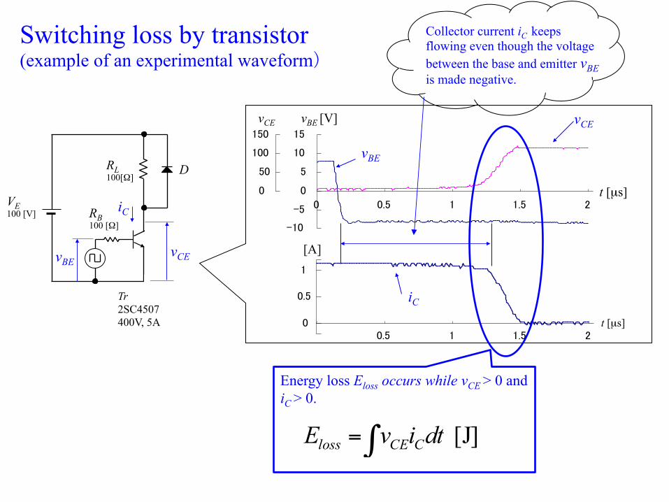
Tr 2SC4507 400V, 5A
vCE
iC
D RL 100[Ω]
vBE
RB 100 [Ω]
VE 100 [V]
iC
0
50
100
150
0.5 1 1.5 2
-10 -5
0
5
10
15
0
t [µs]
t [µs]
vCE
vBE
[A]
vCE vBE [V]
0
0.5
1
0.5 1 1.5 2
Switching loss by transistor (example of an experimental waveform)
Energy loss Eloss occurs while vCE > 0 and iC > 0.
[J] dtivE CCEloss ∫=
Collector current iC keeps flowing even though the voltage between the base and emitter vBE is made negative.
11
-1
1
-VE
VE
-1
1
-VE
VE
-1
1
-VE
VE
fcom / ftri = 1/9 (constant)
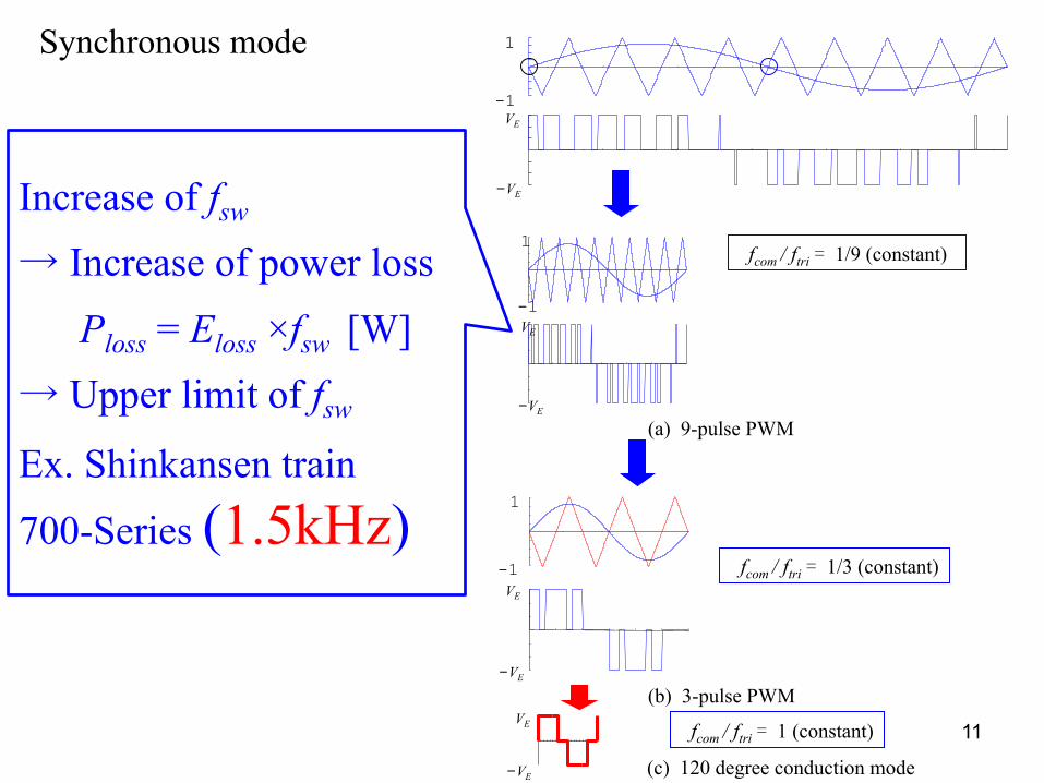
Synchronous mode
-VE
VE
Increase of fsw
→ Increase of power loss
Ploss = Eloss ×fsw [W]
→ Upper limit of fsw
Ex. Shinkansen train
700-Series (1.5kHz) fcom / ftri = 1/3 (constant)
fcom / ftri = 1 (constant)
(b) 3-pulse PWM
(a) 9-pulse PWM
(c) 120 degree conduction mode

12
Speed of the Shinkansen train
Switc
hing
freq
uenc
y
3P 1P
9P
Example of switching between asynchronous mode and synchronous mode
fcom / ftri =1/1 fcom / ftri =1/3 fcom / ftri =1/9
Asynchronous mode Synchronous mode

13
-1
1
-VE
VE
-1
1
-VE
VE
(b) 3-pulse PWM
(a) 9-pulse PWM
Asynchronous mode
Speed
Switc
hing
freq
uncy
Synchronous mode
3P
1P
9P -1
1
-VE
VE
Zero crossing points of the voltage command and triangular waveform always coincide.
Synchronous mode at high speed
-VE
VE
(c) 120 degree conduction mode
fcom / ftri = 1/9 (constant)
fcom / ftri = 1/3 (constant)
fcom / ftri = 1 (constant)

14
If not synchronized!
Asymmetry between positive side and negative side. Waveform varies at every cycle.
Over heating, vibration of motor noisy motor sound

15
300-series ((1990~) Max speed: 285 km/h Main motor: Three phase induction motor Power converter: VVVF Inverter (GTO Thyristor) Switching frequency 420 [Hz] Braking method: Regenerative braking The induction motor’s output power is 130% and its weight is half of that of the DC motor. Regenerative braking was first introduced to Shinkansen trains.
100-series(1985~) Max speed: 275 km/h Main motor: DC series wound motor Power converter: Thyristor type Braking method: Resistance braking
Shinkansen
http://ja.wikipedia.org/wiki/新幹線300系電車 http://ja.wikipedia.org/wiki/新幹線100系電車
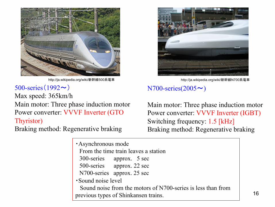
16
500-series(1992~) Max speed: 365km/h Main motor: Three phase induction motor Power converter: VVVF Inverter (GTO Thyristor) Braking method: Regenerative braking
N700-series(2005~) Main motor: Three phase induction motor Power converter: VVVF Inverter (IGBT) Switching frequency: 1.5 [kHz] Braking method: Regenerative braking
・Asynchronous mode From the time train leaves a station 300-series approx. 5 sec 500-series approx. 22 sec N700-series approx. 25 sec ・Sound noise level Sound noise from the motors of N700-series is less than from previous types of Shinkansen trains.
http://ja.wikipedia.org/wiki/新幹線500系電車 http://ja.wikipedia.org/wiki/新幹線N700系電車