power genex electro-pneumatic positioner · prior to using power-genex products, please read and...
TRANSCRIPT

Instruction and Operating Manual
Power Genex Electro-Pneumatic Positioner
EPL / EPR Series <VER 1.5>
www.actuatedvalvesupplies.com.com
Subject to change without prior notice

EPL / EPR Series
1
Contents
1. Safety Instructions ........................................................................................................................................................................................... 3
2 Description ........................................................................................................................................................................................................... 7
3 Principle of Operation .................................................................................................................................................................................... 7
4 Specifications ...................................................................................................................................................................................................... 8
5 Part Numbering System (order code) .................................................................................................................................................... 9
6 Descriptions on Nameplates ..................................................................................................................................................................... 10
7 Internal Views ................................................................................................................................................................................................... 10
7.1. EPL Positioner .................................................................................................................................................................................... 10
7.2. EPR Positioner ................................................................................................................................................................................... 11
8 Installation .......................................................................................................................................................................................................... 11
8.1. Mounting of EPL Positioner ....................................................................................................................................................... 11
Mounting and Attaching Feedback Lever ............................................................................................................. 11 8.1.1.
Position of Span Adjuster According to Actuator Type (RA or DA) ......................................................... 12 8.1.2.
8.2. Mounting of EPR Positioner ....................................................................................................................................................... 12
Mounting with NAMUR type ....................................................................................................................................... 12 8.2.1.
Mounting with Fork Lever Type ................................................................................................................................. 13 8.2.2.
Adjustment of Cam and Indicator ............................................................................................................................ 14 8.2.3.
9 Air Connections ............................................................................................................................................................................................... 15
9.1. EPL Positioner .................................................................................................................................................................................... 15
9.2. EPR Positioner ................................................................................................................................................................................... 15
10 Electrical Connections ................................................................................................................................................................................ 16
10.1. General Wiring ............................................................................................................................................................................... 16
10.2. Wiring for Intrinsic Safety Ex ia IIC T6 ............................................................................................................................... 16
Connection to Terminals.............................................................................................................................................. 16 10.2.1.
Connection to Cable Gland ....................................................................................................................................... 17 10.2.2.
10.3. Wiring for Flameproof Ex dmb IIC T6/T5, Ex dmb IIB T6, Eex md IIB T5 ......................................................... 18
Connection to Cable Gland ....................................................................................................................................... 18 10.3.1.
11 Setting of Span and Zero ........................................................................................................................................................................ 19
12 Position Transmitter and Limit Switches ........................................................................................................................................... 19
12.1. Position Transmitter (4 – 20mA output signal) .............................................................................................................. 20
Board View ......................................................................................................................................................................... 20 12.1.1.
Specifications .................................................................................................................................................................... 20 12.1.2.
With multi-meter tester ............................................................................................................................................... 21 12.1.3.
12.2. SPDT Mechanical Limit Switches (open / close) ............................................................................................................. 21
13 Optional Restricted Pilot Valve Orifice .............................................................................................................................................. 21
14 Troubleshooting Tips .................................................................................................................................................................................. 22
15 Dimensions ...................................................................................................................................................................................................... 23
15.1. EPL Positioner ................................................................................................................................................................................. 23
15.2. EPR Positioner ................................................................................................................................................................................. 24
www.actuatedvalvesupplies.com.comSubject to change without prior notice

EPL / EPR Series
2
1-1 Safety Instructions
These safety instructions are intended to prevent hazardous situations and/or equipment damage. These instructions indicate the level of potential hazard with the labels of “Caution,” “Warning” or “Danger.” They are all important notes for safety and must be followed in addition to International Standards (IEC) Note 1), and other safety regulations.
Note 1) IEC 60079-0 : 2007 EN 60079-0 : 2009 EN 13463-1 : 2009 IEC 60079-1 : 2007 EN 60079-7 : 2007 IEC 60079-11 : 2006 EN 60079-11 : 2007 EN 13463-5 : 2010 IEC 60079-26 : 2004 EN 60079-26 : 2004
Caution Caution indicates a hazard with a low level of risk which, if not avoided, could resultin minor or moderate injury.
Warning Warning indicates a hazard with a medium level of risk which, if not avoided, couldresult in death or serious injury.
Danger Danger indicates a hazard with a high level of risk which, if not avoided, will resultin death or serious injury.
Warning 1. The compatibility of the product is the responsibility of the person who designs the equipment or
decides its specifications.Since the product specified here is used under various operating conditions, its compatibility withspecific equipment must be decided by the person who designs the equipment or decides itsspecifications based on necessary analysis and test results. The expected performance and safetyassurance of the equipment will be the responsibility of the person who has determined itscompatibility with the product. This person should also continuously review all specifications of theproduct referring to its latest catalogue information, with a view to giving due consideration to anypossibility of equipment failure when configuring the equipment.
2. Only personnel with appropriate training should operate machinery and equipment. The productspecified here may become unsafe if handled incorrectly.The assembly, operation and maintenance of machines or equipment including our products must beperformed by an operator who is appropriately trained and experienced.
3. Do not service or attempt to remove product and machinery/equipment until safety is confirmed.1. The inspection and maintenance of machinery/equipment should only be performed after measuresto prevent falling or runaway of the driven objects have been confirmed.2. When the product is to be removed, confirm that the safety measures as mentioned above areimplemented and the power from any appropriate source is cut, and read and understand the specificproduct precautions of all relevant products carefully.3. Before machinery/equipment is restarted, take measures to prevent unexpected operation andmalfunction.
4. Contact POWER-GENEX beforehand and take special consideration of safety measures if theproduct is to be used in any of the following conditions.1. Conditions and environments outside of the given specifications, or use outdoors or in a placeexposed to direct sunlight.2. Installation on equipment in conjunction with atomic energy, railways, air navigation, space, shipping,vehicles, military, medical treatment, combustion and recreation, or equipment in contact with food andbeverages, emergency stop circuits, clutch and brake circuits in press applications, safety equipment orother applications unsuitable for the standard specifications described in the product catalogue.3. An application which could have negative effects on people, property, or animals requiring specialsafety analysis.4. Use in an interlock circuit, which requires the provision of double interlock for possible failure byusing a mechanical protective function, and periodical checks to confirm proper operation.
www.actuatedvalvesupplies.com.comSubject to change without prior notice
EPL / EPR Series
3
1-2 Safety Instructions
Caution
1. The product is provided for use in manufacturing industries.The product herein described is basically provided for peaceful use in manufacturing industries. Ifconsidering using the product in other industries, consult POWER-GENEX beforehand and exchangespecifications or a contract if necessary. If anything is unclear, contact your nearest sales branch.
Limited warranty and Disclaimer/Compliance Requirements The product used is subject to the following “Limited warranty and Disclaimer” and “Compliance Requirements”. Read and accept them before using the product.
Limited warranty and Disclaimer
1. The warranty period of the product is 1 year in service or 1.5 years after the product is delivered.Note 2)Also, the product may have specified durability, running distance or replacement parts. Please consultyour nearest sales branch.
2. For any failure or damage reported within the warranty period which is clearly our responsibility, areplacement product or necessary parts will be provided. This limited warranty applies only to ourproduct independently, and not to any other damage incurred due to the failure of the product.
3. Prior to using POWER-GENEX products, please read and understand the warranty terms anddisclaimers noted in the specified catalogue for the particular products.
Note 2) Vacuum pads are excluded from this 1 year warranty. A vacuum pad is a consumable part, so it is warranted for a year after it is delivered. Also, even within the warranty period, the wear of a product due to the use of the vacuum pad or failure due to the deterioration of rubber material are not covered by the limited warranty.
Compliance Requirements
1. The use of POWER-GENEX products with production equipment for the manufacture of weapons ofmass destruction (WMD) or any other weapon is strictly prohibited.
2. The exports of POWER-GENEX products or technology from one country to another are governedby the relevant security laws and regulations of the countries involved in the transaction. Prior tothe shipment of a POWER-GENEX product to another country, assure that all local rules governingthat export are known and followed.
www.actuatedvalvesupplies.com.comSubject to change without prior notice

EPL / EPR Series
4
1-3 PrecautionsBe sure to read before handling.
Operation
Warning1. Do not operate the positioner outside the specified range as this may cause problems. (Refer to
the specifications.)2. Design the system to include a safety circuit to avoid the risk of danger should the positioner
suffer failure.3. Be sure that exterior lead-in wiring to the terminal box is based on the guidelines for explosion-
protection of manufactory electric equipment when being used as a flame proof, explosion proofconstruction.
4. Do not remove terminal cover in a hazardous location while the power is on.5. Covers for the terminal and body should be in place while operating.6. When using as an intrinsically safe explosion-proof product, do not wire in a hazardous location
while the power is on.
Caution 1. Do not touch the actuator or valve's oscillating section when supply pressure has been added, as
this is dangerous.2. Make sure fingers do not get caught when mounting and aligning the cam.
Cut off the pressure supply and always release the compressed air inside the positioner and actuatorbefore performing this work.
3. Always use with the body cover unit mounted.Moreover, the positioner may not meet degrees of protection IP66 depending on the body covermounting conditions. In order to meet degrees of protection IP66, tighten threads using the propertightening torques (2.8 to 3.0 N·m).
4. Always flush the pipe's inside before piping to ensure foreign objects such as machining chips donot enter the positioner.
5. The actuator opening may become unstable when using the booster relay.6. Always use a ground connection to prevent noise from the input current and to prevent damage
because of static electricity.7. Use the pressure reading on the supplied pressure gauge as an indication.8. The supplied pressure gauge's needle will malfunction if the pressure supply to the internal
mechanism or positioner freezes. Ensure that the pressure gauge's internal parts do not freeze ifusing the pressure gauge in an operating environment with an ambient temperature of less than0°C.
For users
Caution 1. Assemble, operate and maintain the positioners after reading the operation manual tho-roughly
and understanding the content.
www.actuatedvalvesupplies.com.comSubject to change without prior notice

EPL / EPR Series
5
1-4 PrecautionsBe sure to read before handling.
Handling
Caution 1. Avoid excessive vibration or impact to the positioner body and any excessive force to the armature,
as these actions may cause damage to the product. Handle carefully while transporting andoperating.
2. If being used in a place where vibration occurs, using a binding band is recommended to preventbroken wires because of the vibration.
3. When exposed to possible moisture invasion, please take the necessary measures. For example, ifthe positioner is left onsite for long periods, a plug should be put in the piping port and a bodycover unit fitted to avoid water penetration.Take measures to avoid dew condensation inside the positioner if exposed to high temperature andhumidity. Take enough measures against condensation especially when packing for export.
4. Keep magnetic field off the positioner, as this affects its characteristics.
Air Supply
Caution 1. Use only dehumidified and dust extracted clean compressed air as the air supply.2. Use only dehumidified and dust extracted clean compressed clean air as the positioner contains
extrafine orifices such as restrictor and nozzle.Do not use a lubricator.
3. Do not use compressed air containing chemicals, organic solvents, salinity or corrosive gases, as thismay cause malfunction.
4. When operating below the freezing point, protect the positioner from freezing.
Operating Environment
Caution 1. Do not operate in locations with an atmosphere of corrosive gases, chemicals, sea water, or where
these substances will adhere to the regulator.2. Do not operate out of the indicated operation temperature range as this may cause damage to
electronic parts and seal materials to deteriorate.3. Do not operate in locations where excessive vibration or impact occurs.4. If the body cover is being installed in a place where the body cover is exposed to direct sunlight, the
use of a standard body cover without the LCD window is recommended.
www.actuatedvalvesupplies.com.comSubject to change without prior notice

EPL / EPR Series
6
1-5 PrecautionsBe sure to read before handling.
Maintenance
Warning1. After installation, repair or disassembly, connect compressed air and conduct tests
to confirm appropriate function and leakage.Do not use the positioner when noise from the bleeder sounds louder compared with the initialstate, or when it does not operate normally. If these occur, check immediately if assembled andmounted correctly.Never modify electrical construction to maintain explosion-proof construction.
Warning-Potential electrostatic charging hazard1. The non-metallic parts incorporated in the enclosure of this equipment may
generate an ignition capable level of electrostatic charge. Therefore particularlywhen it used for applications that specifically require Group IIC, EPL Gaequipment, the equipment shall not be installed in a location where the externalconditions are conductive to the build-up of electrostatic charge on such surfaces.Additionally, the equipment shall only be cleaned with a damp cloth.
2. The enclosure contains aluminium and is considered to present a potential risk ofignition by impact or friction. Care must be taken during installation and use toprevent impact or friction. Particularly, it must not be used for applications thatspecifically require EPL Ga equipment.
Caution 1. The insulation between an intrinsically safe circuit and a frame of the equipment is
not capable of withstanding a 500V dielectric strength test as defined in CI.6.3.12 ofEN 60079-11:2007. This shall be taken into account during installation.
2. The earthing of enclosure is necessary to maintain Intrinsic Safety because theinsulation between an intrinsically safe circuit and a frame of the equipment is notcapable of withstanding a 500V dielectric strength test. There are two earthingpoints on the equipment. One is provided as an internal earthing point inside rearcover of the equipment for attaching of a cable screen. The other is provided as anexternal earthing point on the left side of the enclosure. Their cross-sectional areasshould be capable of carrying the maximum possible current of theequipment.(Generally, an insulated wire having a cross-sectional area of at least4mm2 is recommended) The cable should be fitted with a spilt ring lock washer tominimize the risk of self-loosening and is of suitable construction for securing ofconductors of cross sections up to 4mm2.
www.actuatedvalvesupplies.com.comSubject to change without prior notice

EPL / EPR Series
7
2 Description
The EPL / EPR series are the intrinsically safe electro-pneumatic positioners that can be used in a
hazardous area (Zone 1) and worked by a torque motor with 4-20mA input signals @ 24VDC
power supply for operation of the control valves.
3 Principle of Operation
< EPL Positioner > < EPR Positioner >
As the signal current from the controller increases, the plate spring of the torque motor works as
a pivot. As the armature receives the rotary torque in the counter-clockwise direction, the counter-
weight is pushed to the left, the clearance between the nozzle and the flapper will increase, and
the nozzle back pressure will decrease. As a result, the exhaust valve of the pilot valve moves to
the right, and the output pressure of OUT1 increases to move the actuator diaphragm.
The valve stem goes up or down by the movement of the actuator diaphragm, and the feedback
spring lengthens or shortens by the movement of the feedback lever. The valve stem stays in the
position where the spring force is balanced with the force generated by the input current in the
torque motor. The compensation spring is for direct feedback of the motion of the exhaust valve
and is connected to the counter weight to enhance the stability of the loop. The zero point is
adjusted by changing the zero adjustment spring tension.
www.actuatedvalvesupplies.com.comSubject to change without prior notice
EPL / EPR Series
8
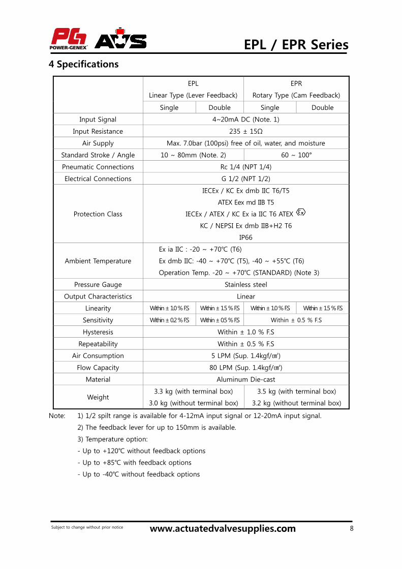
4 Specifications
EPL
Linear Type (Lever Feedback)
EPR
Rotary Type (Cam Feedback)
Single Double Single Double
Input Signal 4~20mA DC (Note. 1)
Input Resistance 235 ± 15Ω
Air Supply Max. 7.0bar (100psi) free of oil, water, and moisture
Standard Stroke / Angle 10 ~ 80mm (Note. 2) 60 ~ 100°
Pneumatic Connections Rc 1/4 (NPT 1/4)
Electrical Connections G 1/2 (NPT 1/2)
Protection Class
IECEx / KC Ex dmb IIC T6/T5
ATEX Eex md IIB T5
IECEx / ATEX / KC Ex ia IIC T6 ATEX
KC / NEPSI Ex dmb IIB+H2 T6
IP66
Ambient Temperature
Ex ia IIC : -20 ~ +70 (T6)
Ex dmb IIC: -40 ~ +70 (T5), -40 ~ +55 (T6)
Operation Temp. -20 ~ +70 (STANDARD) (Note 3)
Pressure Gauge Stainless steel
Output Characteristics Linear
Linearity Within ± 1.0 % F.S Within ± 1.5 % F.S Within ± 1.0 % F.S Within ± 1.5 % F.S
Sensitivity Within ± 0.2 % F.S Within ± 0.5 % F.S Within ± 0.5 % F.S
Hysteresis Within ± 1.0 % F.S
Repeatability Within ± 0.5 % F.S
Air Consumption 5 LPM (Sup. 1.4kgf/)
Flow Capacity 80 LPM (Sup. 1.4kgf/)
Material Aluminum Die-cast
Weight 3.3 kg (with terminal box)
3.0 kg (without terminal box)
3.5 kg (with terminal box)
3.2 kg (without terminal box)
Note: 1) 1/2 spilt range is available for 4-12mA input signal or 12-20mA input signal.
2) The feedback lever for up to 150mm is available.
3) Temperature option:
- Up to +120 without feedback options
- Up to +85 with feedback options
- Up to -40 without feedback options
www.actuatedvalvesupplies.com.comSubject to change without prior notice

EPL / EPR Series
9
5 Part Numbering System (order code)
EP x — x x x x x x x x x
Actuator action Linear type L
Rotary type R
Protection Class:
KC / NEPSI flameproof Ex dmb IIB+H2 T6
IECEx / KC flameproof Ex dmb IIC T6/T5
ATEX flameproof Eex md IIB T5
IECEx / ATEX / KC intrinsically safe Ex ia IIC T6
Weatherproof to IP66
F
D
A
I
W
Feedback Shaft Linear type 10 ~ 40mm stroke A
10 ~ 80mm stroke B
Up to 150mm stroke C
Rotary type Fork lever M6x40L F
NAMUR shaft (direct mounting) N
Gauge 6 bar (90psi) 1
10 bar (150psi) 2
Pilot Valve Orifice Standard(actuator volume over 180) S
Small orifice (Φ1.0 or Φ0.7)(actuator volume 90~180) M
Position Feedback
(only for
weatherproof
type)
None N
Analog position transmitter (4-20mA output signal) O
Smart position transmitter (4-20mA output signal) – only for EPR S
2 x SPDT limit switch – only for EPR L
2 x proximity sensor P&F NJ2-V3-N – only for EPR P
O + L – only for EPR M
O + P – only for EPR Q
Connection
Threads
(pneumatic –
electrical)
PT(Rc) 1/4 – PF(G) 1/2 (standard) 3
NPT 1/4 - NPT 1/2 4
Rc1/4 - M20 x 1.5 5
Dome Indicator
(only for EPR)
Flat indicator (standard) N
Dome Indicator D
Operating
Temperature
Ex ia IIC : -20 ~ +70 (T6)
Ex dmb IIC: -40 ~ +70 (T5), -40 ~ +55 (T6)
Weatherproof: -20 ~ +70
T
+120 (without feedback option) H
+85 (with feedback option)
-40 (without feedback option) L
Mounting
Bracket
None N
DIN / IEC 534 (for EPL ) L
DIN VDI/VDE 3845 (for EPR-NAMUR) R
DHCT bracket 80x30 (for EPR - Fork lever type) F
www.actuatedvalvesupplies.com.comSubject to change without prior notice

EPL / EPR Series
10
6 Descriptions on Nameplates
< Intrinsically safe Ex ia IIC T6> < Flameproof Ex dmb IIC T6/T5 >
- Model No.: Part number is described.
- Input Signal: 4-20mA current input signal is described.
- Supply Air Pressure: The supply air pressure range of 1.4 ~ 7 bar is described.
- Ambient Temp.: The operating ambient temperature range of -20 ~ +70 is described.
- Serial No.: A serial number and a manufacturing date are described.
- Ui , Ii, Ri, Pi, Li, Ci : Intrinsic safety parameters are described.
- Certification bodies and certificate numbers are described.
7 Internal Views
Never move the seat adjuster. It was already set at the factory precisely.
7.1. EPL Positioner
Output pressure gauge
Zero adjusting screw
Supply pressure gauge
Terminal box
Torque motor Case
Feedback lever
Nozzle
Span adjusting screw
Pilot valve
Seat adjuster
Stopper screw
Auto/Manual screw
www.actuatedvalvesupplies.com.comSubject to change without prior notice
EPL / EPR Series
11
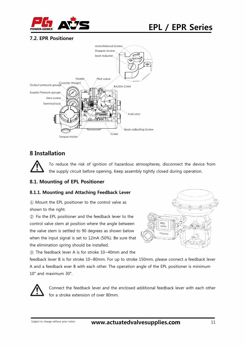
7.2. EPR Positioner
8 Installation
To reduce the risk of ignition of hazardous atmospheres, disconnect the device from
the supply circuit before opening. Keep assembly tightly closed during operation.
8.1. Mounting of EPL Positioner
Mounting and Attaching Feedback Lever 8.1.1.
① Mount the EPL positioner to the control valve as
shown to the right.
② Fix the EPL positioner and the feedback lever to the
control valve stem at position where the angle between
the valve stem is settled to 90 degrees as shown below
when the input signal is set to 12mA (50%). Be sure that
the elimination spring should be installed.
③ The feedback lever A is for stroke 10∼40mm and the
feedback lever B is for stroke 10~80mm. For up to stroke 150mm, please connect a feedback lever
A and a feedback ever B with each other. The operation angle of the EPL positioner is minimum
10° and maximum 30°.
Connect the feedback lever and the enclosed additional feedback lever with each other
for a stroke extension of over 80mm.
www.actuatedvalvesupplies.com.comSubject to change without prior notice

EPL / EPR Series
12
< Installation of Elimination Spring >
Position of Span Adjuster According to Actuator Type (RA or DA) 8.1.2.
When adjusting or replacing a span adjuster, be sure to shut off air supply to the EPL
positioner. Otherwise, the EPL positioner might react suddenly and cause damage or
injury.
Span adjuster is set to RA (reverse acting) as a standard factory setting. But it is necessary to re-
set its position for DA (direct acting) as shown below.
< RA Type – Factory setting> < DA Type >
8.2. Mounting of EPR Positioner
Mounting with NAMUR type 8.2.1.
The EPR positioner has the NAMUR shaft as standard
which can be directly mounted to the top pinion
(VDI/VDE 3845) of the pneumatic rotary actuator.
www.actuatedvalvesupplies.com.comSubject to change without prior notice

EPL / EPR Series
13
① Mount the NAMUR multi-size bracket to the pneumatic rotary actuator with the enclosed bolts
(4 x M5) as shown to the right.
② Mount the EPR positioner to the bracket and insert the EPR positioner feedback shaft into the
actuator top pinion (output shaft) as shown to the
right.
③ Fix the EPR positioner to the bracket with the
enclosed bolts (4 x M6).
A multi-size bracket is assembled for 80x30x20 as a
standard factory setting. But the user can re-
assemble it for 80x30x30, 130x30x20, and
130x30x30 according to requirements as shown
below.
Mounting with Fork Lever Type 8.2.2.
Mount the EPR positioner to the actuator with
DHCT bracket (80x30) as shown to the right. Be
sure that the feedback lever shaft “A”
is placed in the orifice for the fork
lever “B” and they are in alignment
with a rotary actuator output shaft.
Clockwise movement Counter-clockwise Movement
www.actuatedvalvesupplies.com.comSubject to change without prior notice

EPL / EPR Series
14
Adjustment of Cam and Indicator 8.2.3.
When adjusting or replacing cams, be sure to shut off air supply to the EPR positioner.
Otherwise, the EPR positioner might react suddenly and cause damage or injury.
- RA (reverse acting) is a standard factory setting.
① Loosen a flange nut on a cam and reverse a cam for DA setting. Match the part of the cam
with "0" marked on it with the center of bearing as shown below. The span adjusting arm unit
should now be aligned.
< Reverse Acting(RA) > < Direct Acting (DA) >
② Tighten the flange nut of the cam after setting the cam.
③ After cam installation, proceed to adjust zero and span. Once this is complete, secure the
indicator with the bolt (M6) to the feedback shaft according to the actuator type (RA or DA) as
shown below. The position for the indicator should be arranged in the scale (0 - 90°) shown on
the cover.
[RA] [DA]
www.actuatedvalvesupplies.com.comSubject to change without prior notice

EPL / EPR Series
15
9 Air Connections
9.1. EPL Positioner
9.2. EPR Positioner
www.actuatedvalvesupplies.com.comSubject to change without prior notice

EPL / EPR Series
16
10 Electrical Connections
10.1. General Wiring
10.2. Wiring for Intrinsic Safety Ex ia IIC T6
Connection to Terminals 10.2.1.
The intrinsically safe EPL / EPR series are designed for the intrinsic safety standards of
IEC/EN 60079-0, IEC/EN 60079-11, EN 13463-1, EN 13463-5. Note that it can be
influenced by an electrical or magnetic energy from other electronic devices. Therefore,
do not open when it is energized.
① Always check that the electrical load is within the range stated on the
nameplate. Failure to remain within electrical ratings may result in damage to or
premature failure of the electrical switches, sensors or transmitter electronics.
② Check polarity of + and – exactly and connect wires.
③ When it is necessary to open the positioner cover at a humid place, more
attention is required. It may cause a serious damage or malfunctions.
외부 접지 GroundGround
www.actuatedvalvesupplies.com.comSubject to change without prior notice

EPL / EPR Series
17
① Select a proper safety barrier that can meet parameters of the intrinsically safe EPL /
EPR positioner. Also, consider Li and Ci according to a cable length.
② Be sure to disconnect a power supply before connecting wires to terminals and
confirm + - clearly when connecting wires.
③ Tighten a fixing screw so that a cable cannot be pulled out or left away.
④ Protect cables from an external damage.
⑤ Ground the intrinsically safe the EPL / EPR positioner.
Connection to Cable Gland 10.2.2.
1. Cable gland cover
2. Cable gland Sealing
3. Cable gland body
4. Junction body
① Dis-assemble a cable gland by turning a cable gland cover counter-clockwise
② Insert a cable into the positioner through a cable gland as shown above and fix by turning a
cable gland cover clockwise.
Below are specifications of a cable that fits the cable gland supplied as standard with
intrinsically safe EPL / EPR positioner.
- External diameter: Max. 12.5mm
- Internal diameter: Min. 9mm
Green
www.actuatedvalvesupplies.com.comSubject to change without prior notice

EPL / EPR Series
18
10.3. Wiring for Flameproof Ex dmb IIC T6/T5, Ex dmb IIB T6, Eex md IIB T5
The EPL / EPR series certified to ATEX Eex md IIB T5 must be connected to a fuse with
the following ratings:
- Max 125mA, breaking capacity 35A
- Suitable 1/2” PF threaded certified EEx d cable glands and plugs must be used.
① Be sure to use the flameproof-approved wires and cable glands in the gas area or in
the potentially-explosive area. Use the cables suitable for the diameter of the NBR
packing when using the flameproof-approved cable glands.
② Cable entries have PF 1/2(G 1/2).
③ Do not open the terminal box cover when energized. Disconnect a power supply
before opening the terminal box cover and wait until a power supply is cut off
completely.
④ Use the ring type wire connector so that it cannot be disconnected easily.
Connection to Cable Gland 10.3.1.
① Open the terminal box cover by loosening the fixing bolt on the terminal box cover.
② Install the flameproof-approved cable glands tightly and insert a wire into the terminal box.
Use and fix the NBR packing tightly so that the inside of the terminal box can be sealed up.
③ Connect external + to internal + and external – to internal –.
④ Fix the terminal bolts tightly.
⑤ Close the terminal box cover and turn the fixing bolt completely.
www.actuatedvalvesupplies.com.comSubject to change without prior notice

EPL / EPR Series
19
11 Setting of Span and Zero
< Zero Adjuster > < Span Adjuster – EPL> < Span Adjuster - EPR >
① Check the proper installation of the EPL positioner and the feedback lever.
② Check the proper position of a span adjuster according to the actuator type (direct acting or
reverse acting).
③ Connect all air connections.
④ Supply air and set the input signal to 4mA. Turn the zero adjusting screw clockwise or counter
clockwise to set the zero position.
⑤ Check the stroke of the control valve by setting the input signal to 20mA. If the stroke does
not meet 100%, turn the span adjusting screw clockwise or counter clockwise until 100% is
reached.
⑥ Set the input signal back to 4mA and adjust the zero adjusting screw until the zero point is
reached.
⑦ Repeat the process of ④ to ⑥ until the desired set points are reached.
⑧ If the strokes of the control valve perfectly meet 0% and 100%, each setting point of 8, 12, and
16mA is automatically reached.
Due to variations in circuitry and environmental effects, often 0% is set at 4.5mA and
100% at 19.5mA to make sure that at the end points the valve will be fully open or fully
closed.
12 Position Transmitter and Limit Switches
www.actuatedvalvesupplies.com.comSubject to change without prior notice

EPL / EPR Series
20
12.1. Position Transmitter (4 – 20mA output signal)
Board View 12.1.1.
Specifications 12.1.2.
Power Supply Rating 5.5 ~ 30V DC loop-powered
Recommended Power Supply 24V DC
Output Signal 4~20mA
Operating Temperature -20º to 70
Load Impedance 0~600 ohms
Max. Output 30mA DC
Linearity ± 1.0 %
Hysteresis 1.0 % of full scale
Repeatability ± 0.5 % of full scale
Adjustment Zero and Span in terminal box
With mA loop calibrator 12.1.2.A.
With multi-meter tester 12.1.2.B.
www.actuatedvalvesupplies.com.comSubject to change without prior notice

EPL / EPR Series
21
With multi-meter tester 12.1.3.
① Select RA or DA on a board in the terminal box. For reference, RA (reverse acting) is a standard
factory setting.
② Supply 4mA input signal and turn the zero adjusting screw on a board clockwise or counter
clockwise until output signal becomes 4mA.
③ Supply 20mA input signal and turn the span adjusting screw on a board clockwise or counter
clockwise until output signal becomes 20mA.
④ Repeat the process of ② to ③ until output signal approaches input signal.
① Be sure that Span and Zero of the EPR positioner should be exactly set before
setting Span and Zero of the position transmitter.
② Be sure that 5.5 - 30V DC should be supplied in case of using the mA tester
(multimeter tester).
③ Check if the transmitter power supply lamp is on.
12.2. SPDT Mechanical Limit Switches (open / close)
Contacts SPDT Form C
AC Rating 16A 1/2HP 125/250VAC
DC Rating 0.6A 125VDC / 0.3A 250VDC
Adjustment Cams with set screws (L-wrench included for setting)
13 Optional Restricted Pilot Valve Orifice
Before removing the pilot valve, be sure to disconnect the EPL / EPR positioner from
the signal and compressed air source
For improved control using smaller actuators, a restricted
pilot valve orifice kit is included with the EPL / EPR
positioner. To install, the pilot valve must be removed from
the EPL / EPR positioner. Remove four screws holding the
pilot valve to the EPL / EPR positioner body. As you remove
the pilot valve, be sure to hold the compensation spring in
place. Flip the valve so the bottom faces you. Remove the
O-rings from the out 1 and out 2 ports (as shown in the
diagram at right). Place the orifice plates in their place with
new O-rings above them, and re-install the pilot valve, making sure the compensation spring is
back in place. The EPL / EPR positioner is now set up for smaller actuators.
www.actuatedvalvesupplies.com.comSubject to change without prior notice

EPL / EPR Series
22
14 Troubleshooting Tips
Trouble Solution
Hunting happens with a small
pneumatic actuator
The actuator is very small. Install two orifices at the
bottom of the pilot valve as instructed in 12. Optional
Restricted Pilot Valve Orifice.
If the actuator is not small, check if a position shaft is
inserted into the output shaft of the actuator exactly. If
there is a gap between these shafts, make it tight.
Valve is always open regardless of
input signal.
The orifice of the Auto/Manual screw on the pilot valve is
clogged. Disconnect supply air and clean the orifice with
a wire attached inside of the EPR positioner cover as
shown below.
Never move the seat adjuster. It was already set at
the factory precisely.
Valve is always opens or closed
with input signal
The air connections are not made properly. Check again if
the pneumatic actuator type is RA (reverse acting) or DA
(direct acting) and make the proper air connections. See
Air Connections.
Linearity is very poor
① Check if the 1.4 ~ 7 bar air is supplied properly.
② Check if the EPL positioner is installed properly. The
feedback lever should be positioned horizontally at 50%
input signal.
③ Check if the EPR positioner and the mounting bracket
are installed properly and tightly.
④ Check if Zero and Span are set properly.
Hysteresis is very poor
① Check if the mounting bracket is installed tightly.
② Check if the valve stem pin of the EPL positioner is
installed and connected to the feedback lever properly.
③ Check if the feedback lever spring of the EPL
positioner is installed properly.
Valve moves too slowly An actuator is too big. Use the air volume booster.
www.actuatedvalvesupplies.com.comSubject to change without prior notice
EPL / EPR Series
23
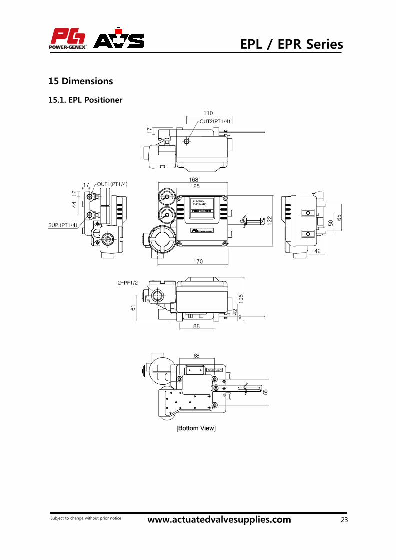
15 Dimensions
15.1. EPL Positioner
www.actuatedvalvesupplies.com.comSubject to change without prior notice

EPL / EPR Series
24
15.2. EPR Positioner
www.actuatedvalvesupplies.com.comSubject to change without prior notice

EPL / EPR Series
www.actuatedvalvesupplies.com 25
Warranty1. The warranty period of the product is 1 year in service or 1.5 years after the product is
delivered.
2. For any failure or damage reported within the warranty period which is clearly our
responsibility, a replacement product or necessary parts will be provided. This limited
warranty applies only to our product independently, and not to any other damage
incurred due to the failure of the product.
3. Prior to using POWER-GENEX products, please read and understand the warranty terms
and disclaimers noted in the specified catalogue for the particular products.
4. If maintenance is required, you can contact with distributors, agents or directly with
Power-Genex. A proper and satisfactory customer service will be provided.
Subject to change without prior notice