power in ac circuit by group. group muhammad umer farooqbs-p-13-28 muhammad faisal khanbs-p-13-57 ...
TRANSCRIPT

POWER IN AC CIRCUITBY
Group

GROUP
MUHAMMAD UMER FAROOQ BS-P-13-28
MUHAMMAD FAISAL KHAN BS-P-13-57
MUHAMMAD AKHTAR BS-P-13-31
MUHAMMAD USMAN NAJEEB BS-P-13-67

Power
Mechanics
rate of doing work per unit time
P=W/t
CIRCUIT
The work done dW by a source of emf to unit charge dq is given by
dW=Ɛ dq
the rate of doing work by source of emf to unit charge in unit time
called power. P=dW/dt

POWERA.C
P=
=R/2
=
=cos
D.C P=VI
P=R
P=/R

Cases
IDEAL case
ideal capacitive and inductive elements have no internal resistance.
so power will go on resistive element and then it is given by
P=t-
full A.C circuit
sint sin(t-)
=

DERIVATIONS
P=t-
=R/2
=
since /2)
=R
In RLC circuit
P=t- sin
P=t cos- sin
P=t cos-
The t term gives the value ½.,wheras the term gives ‘0’
So we can write it as
=cos/2 /
=cos /2

Power factor
=cos
in this, cos is called power factor. Power factor for series RLC circuit. tan we can show that
cos
the power delivered to the circuit by the source of emf is maximum when cos.when circuit is purely resistive, no capacitor or inductor , or at resonance when so that Z=R. then average power is
=

Phase angle
an angle representing a difference in phase, 360 degrees (2π radians) corresponding to one complete cycle.
The angle between two alternating quantities
PHASOR DIAGRAM
the diagram in which phasors represented by the open arrows, rotate counterclockwise with an angular frequency about the origin.

Properties of phasor diagram
The length of phasors
proportional to max. value of alternating quantity
Projection of phasor on a vertical axis
instantaneous value of alternating quantity
arrows on vertical axis represent the time varying quantities
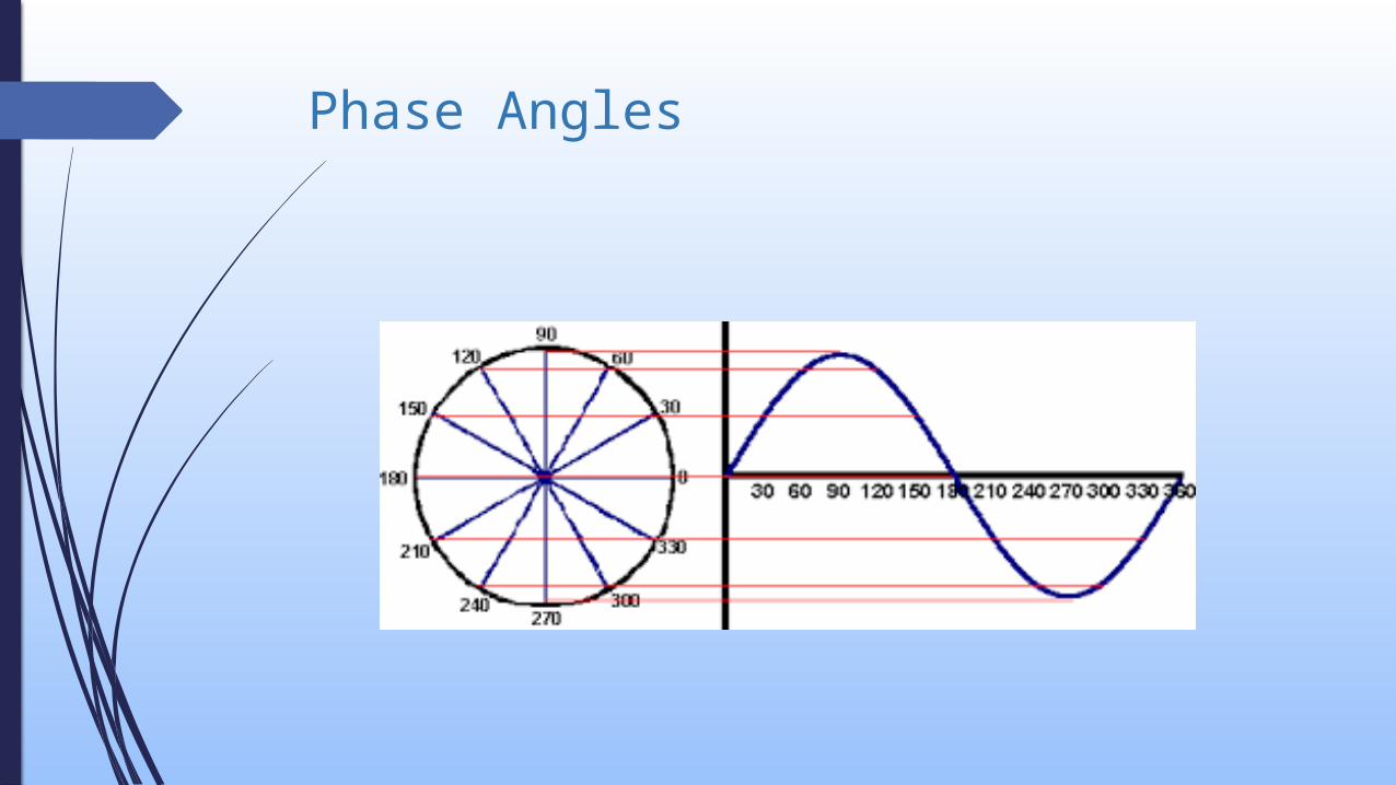
Phase Angles

resistance circuit
waveform phasor daigram
𝑉 𝑅
𝐼𝑅t
𝜔

Capacitor circuit

Inductor circuit
𝑉 𝐿
𝐼𝐿
90𝑜
𝜔

RLC circuit

Power companies
frequency 60Hz
Not concerned
whether you use purely resistive device in which power dissipated in phase
with the source of emf
or
partialy capacitive or inductive device.
as motor

Power companies measurement
Two cases
1. if the power companies measured your energy use in a time smaller than 1/60 s they would notice variations in the rate at which you use energy.
2. measuring over a time longer than 1/60 s only the average rate of energy consumption becomes important.

Question & Answer

SPECIAL THANKS
DR. FAYYAZ HUSSAIN

THANKS
GROUP MEMBERS

THANKS
BY
GROUP MEMBERS