power lv activefilters pqfi -pqfm pqfk -pqfsfile/section+3_active+filters_pfq.pdf · a b b n....
TRANSCRIPT

©AB
B n.
v. -
1-
PowerIT LV Active FiltersPQFI - PQFMPQFK - PQFS
ABB Active Filters : WhenPower Quality matters!
©AB
B n.
v. -
2
The ultimate solution to poor LV Power Quality
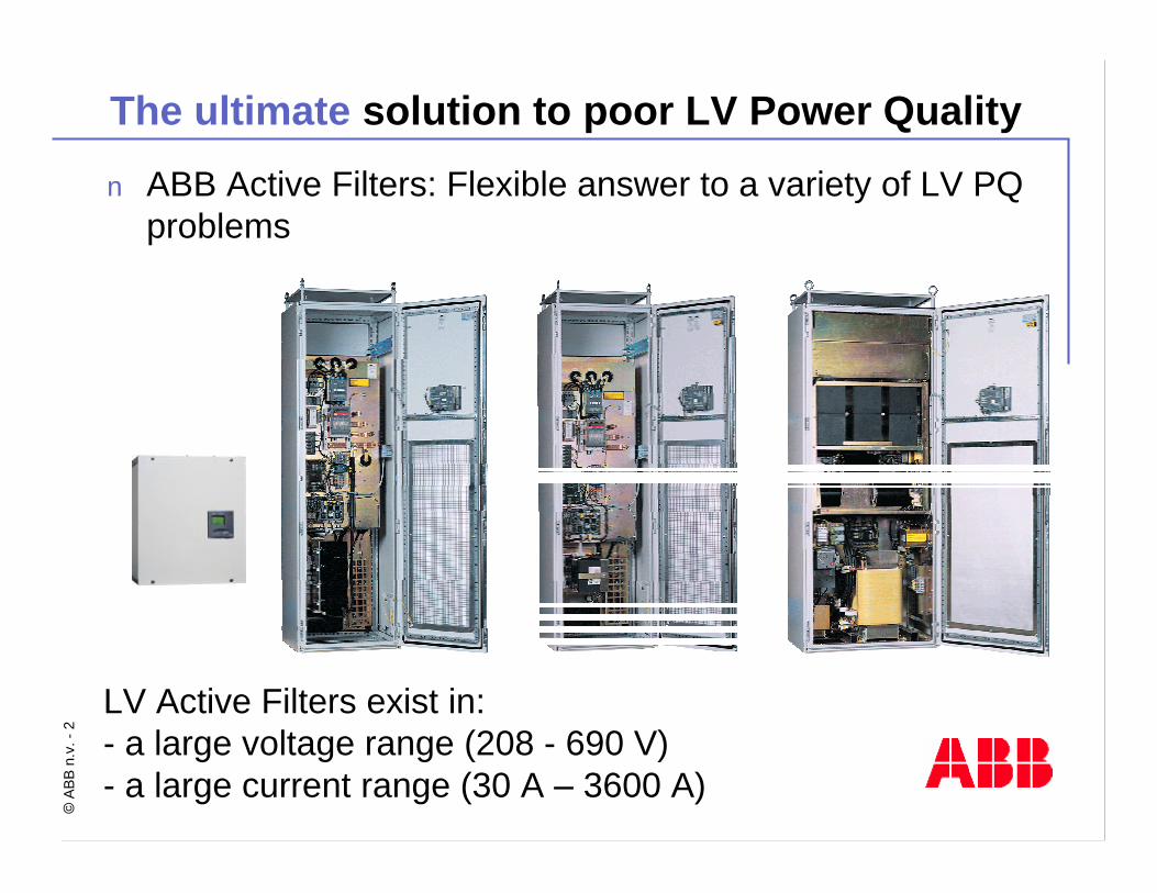
n ABB Active Filters: Flexible answer to a variety of LV PQ problems
LV Active Filters exist in: - a large voltage range (208 - 690 V)- a large current range (30 A – 3600 A)
©AB
B n.
v. -
3
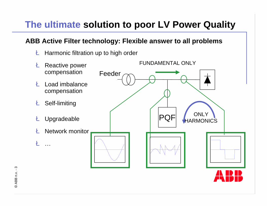
ABB Active Filter technology: Flexible answer to all problemsè Harmonic filtration up to high order
è Reactive power compensation
è Load imbalancecompensation
è Self-limiting
è Upgradeable
è Network monitor
è…
PQF
-1 . 3
1 . 3
0 3 6 0
-1 .3
1 .3
0 3 60
-1 . 3
1 . 3
0 3 6 0
FeederFUNDAMENTAL ONLY
ONLY HARMONICS
The ultimate solution to poor LV Power Quality
©AB
B n.
v. -
4
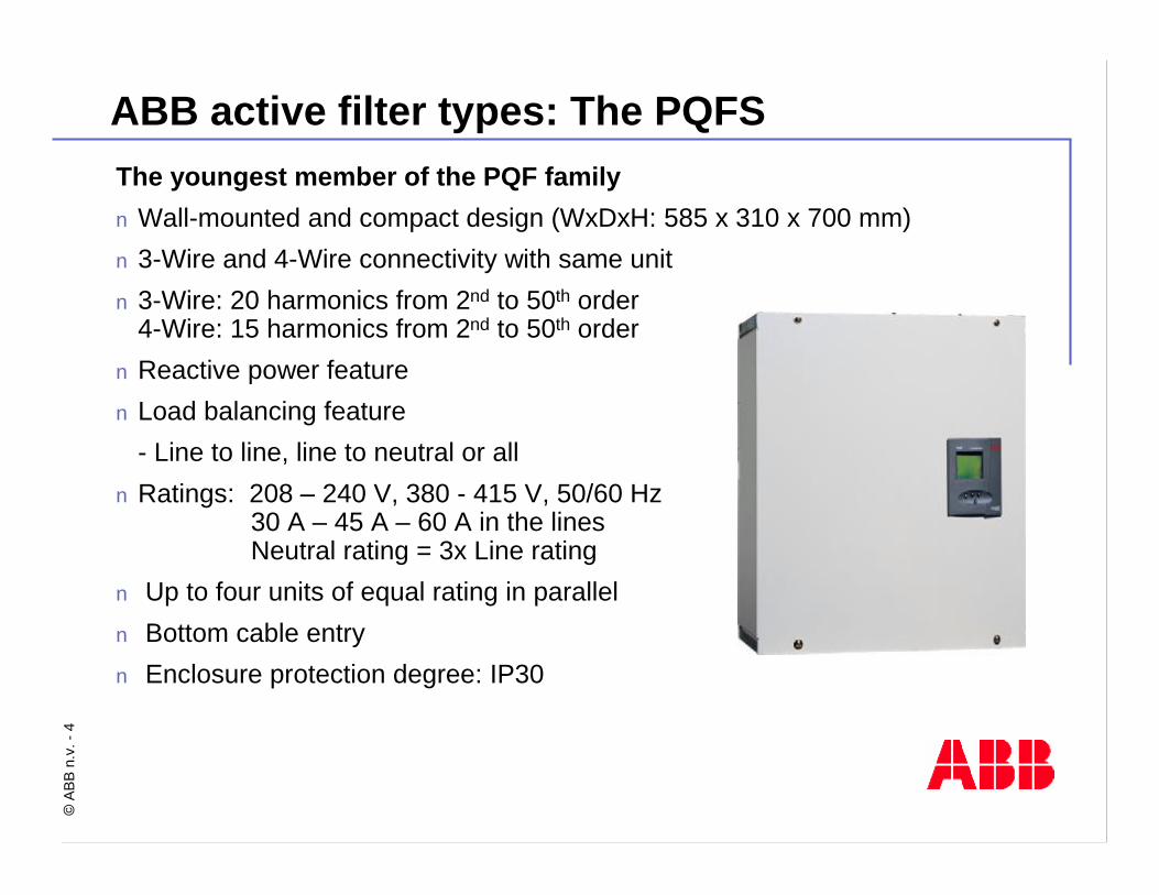
ABB active filter types: The PQFSThe youngest member of the PQF familynWall-mounted and compact design (WxDxH: 585 x 310 x 700 mm)n 3-Wire and 4-Wire connectivity with same unitn 3-Wire: 20 harmonics from 2nd to 50th order
4-Wire: 15 harmonics from 2nd to 50th order n Reactive power featuren Load balancing feature
- Line to line, line to neutral or alln Ratings: 208 – 240 V, 380 - 415 V, 50/60 Hz
30 A – 45 A – 60 A in the linesNeutral rating = 3x Line rating
n Up to four units of equal rating in paralleln Bottom cable entryn Enclosure protection degree: IP30
©AB
B n.
v. -
5
ABB active filter types: The PQFSn Load balancing
- phase to phase (as in PQF-K-I-M series)- phase to neutral (unique in the active filter world, only PQFS and PQFK)
è Allows to eliminate the 50/60 Hz neutral current due to unbalancedloads connected between phase and neutral, e.g. datacenter protection
è Reduces voltage between neutral and ground conductors

©AB
B n.
v. -
6
ABB active filter types: The PQFK
n 4-wire active filter for neutral current and line current filtering
n 15 harmonics from 2nd to 50th ordern Reactive power and balancing feature
(phase to phase and phase to neutral)n Ratings: 208 – 415 V, 50/60 Hz
40 A – 70 A – 100 A in the linesNeutral rating = 3x Line rating
n Up to four units of equal rating in paralleln Top and bottom cable entryn Available in cubicle (IP21) and
in plate version (IP00)è Cubicle dimensions: 600*600*2150 mmè Plate dimensions: 498*400*1697 mm

©AB
B n.
v. -
7
ABB active filter types: The PQFMn 3-wire active filter for line current filteringn 20 harmonics from 2nd to 50th ordern Reactive power and line balancing featuren Ratings: 50/60 Hz
n Up to eight units of equal or non-equal rating in parallel
n Top and bottom cable entryn Available in cubicle (IP21) and in plate
version (IP00)è Cubicle dimensions: 600*600*2150 mmè Plate dimensions: 498*400*1696 mm
2 0 8 V ≤ U ≤ 4 8 0 V 4 8 0 V < U ≤ 6 9 0 V
I [A ] S m a ll 7 0
I [A ] M e d iu m 1 0 0 1 0 0 *
I [A ] L a rg e 1 3 0
N r h a rm s 2 0 2 0
* F o r s y s te m v o lta g e s > 6 0 0 V , th e c u r re n t ra t in g m a y b e d e ra te d a u to m a t ic a lly d e p e n d in g o n th e o p e ra t in g te m p e ra tu r e
©AB
B n.
v. -
8
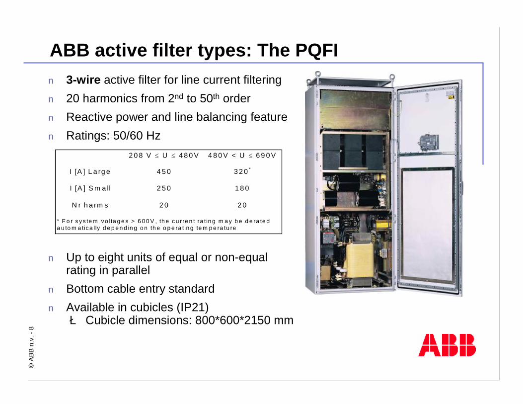
n 3-wire active filter for line current filteringn 20 harmonics from 2nd to 50th ordern Reactive power and line balancing featuren Ratings: 50/60 Hz
n Up to eight units of equal or non-equal rating in parallel
n Bottom cable entry standardn Available in cubicles (IP21) è Cubicle dimensions: 800*600*2150 mm
ABB active filter types: The PQFI
2 0 8 V ≤ U ≤ 4 8 0 V 4 8 0 V < U ≤ 6 9 0 V
I [A ] L a rg e 4 5 0 3 2 0 *
I [A ] S m a ll 2 5 0 1 8 0
N r h a rm s 2 0 2 0
* F o r s ys te m vo lta g e s > 6 0 0 V , th e c u rre n t ra tin g m a y b e d e ra te d a u to m a tica lly d e p e n d in g o n th e o p e ra tin g te m p e ra tu re
©AB
B n.
v. -
9
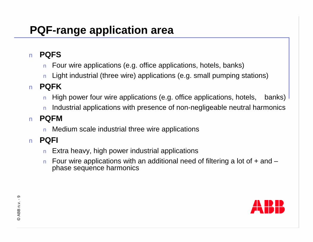
PQF-range application area
n PQFSn Four wire applications (e.g. office applications, hotels, banks)n Light industrial (three wire) applications (e.g. small pumping stations)
n PQFKn High power four wire applications (e.g. office applications, hotels, banks)n Industrial applications with presence of non-negligeable neutral harmonics
n PQFMn Medium scale industrial three wire applications
n PQFIn Extra heavy, high power industrial applicationsn Four wire applications with an additional need of filtering a lot of + and –
phase sequence harmonics

©AB
B n.
v. -
10
n Filters up to 20 (PQFM/I) individually selectable harmonics simultaneously in a range up to the 50th harmonic (15 harmonics for PQFK & PQFS operating in 4 wire mode)
n Desired harmonic levels can be preset for each individual harmonic n Unsurpassed harmonic attenuation factor (≥ 97% typically)n Operates with closed loop control for best accuracyn Stepless load balancing and reactive power compensation featuren Different modes of operation and smooth mode changing strategyn Auto temperature derating function
If ambient temperature increases beyond acceptable limits (e.g. faulty airco) the filter will auto-derate smoothly (down to max. 50% of its rating) and inform customer of this. After correction of the problem, the filter will resume original rating automatically
Why use the PQF range of Active Filters (1)?…because it is the best active filter around!

©AB
B n.
v. -
11
Highest ← PRIORITY → Lowest
Mode 1 Filtering to curve
Maximum filtering
Reactive compensation
Mode 2 Filtering to curve
Reactive compensation
Maximum filtering
Mode 3 Filtering to curve
Reactive compensation
Different modes of operation
Highest ← PRIORITY → Lowest
Mode 1 Filtering to curve
Maximum filtering
Reactive compensation
Mode 2 Filtering to curve
Reactive compensation
Maximum filtering
Mode 3 Filtering to curve
Reactive compensation
Reactive compensation: - none- dynamic (cosφ target)- static (constant reactive power)- Load balancing combined with reactive compensation

©AB
B n.
v. -
12
Smooth mode changing strategy
Max. Filtering &Q Compensation
MaximumFiltering
Filtering toCurve
Filtering toHardware Limits
Load increase
Loaddecrease

©AB
B n.
v. -
13
Why is it important to filter a large range?
Filter upto H13
Filter upto H25
ABBABB
Filter upto H50
This speaks for This speaks for
itself and foritself and for
è Technical requirements
è Regulation requirements

©AB
B n.
v. -
14
Example 1: Induction heating application
T12 MVA6%400 V
T22 MVA6%400 V
T32 MVA6%400 V
91.2 MVA20 kV
PQFA296 kVA(428 A)
Drives945 kVA(1364 A)
700 kvar7%
(1010 A)
400 kvar7%
(577 A)
400 kvar7%
(577 A)
Drives315 kVA(455 A)
Drives315 kVA(455 A)
3200/515 VA To T1
Problem:§ High frequency components disturb production system§ Harmonic loads overload detuned banks

©AB
B n.
v. -
15
Example 1: Induction heating application
-3000
-2000
-1000
0
1000
2000
3000
0 5 10 15 20 25 30 35 40Time [ms]
Line
cur
rent
[A]
-3000
-2000
-1000
0
1000
2000
3000
0 5 10 15 20 25 30 35 40Time [ms]
Line
cur
rent
[A]
Initial line current
High frequency content
Filtered line current
Perfect sine wave
Solution: ABB active filter

©AB
B n.
v. -
16
Example 1: Induction heating application
0%
2%
4%
6%
8%
10%
12%
14%
0 2 4 6 8 10 12 14 16 18 20 22 24 26 28 30 32 34 36 38 40 42 44 46 48 50Frequency [Harmonics]
Cur
rent
dis
tort
ion
[%]
Initial line current Filtered line current
Effect onhigh frequencies
0%
2%
4%
6%
8%
10%
12%
14%
0 2 4 6 8 10 12 14 16 18 20 22 24 26 28 30 32 34 36 38 40 42 44 46 48 50
Frequency [Harmonics]
Cur
rent
dis
tort
ion
[%]
Solution: ABB active filter

©AB
B n.
v. -
17
Why select individual harmonics and levels?
n Filter optimizes operation for each individual harmonic(óWideband systems)
n The user can allocate resources to the harmonics he needs to filterand can forget about the others(óWideband systems)è Efficient use of resources
n The user can put filtering levels in accordance with the regulations/technical needs(óWideband systems)è Efficient use of resources
n The filter can be used in parallel with existing passive filter units(óWideband systems)
!!! Beware of wideband systems !!!

©AB
B n.
v. -
18
Example 2: Cable car application
230kW 230kW PQF
10kV/0.4kV 630kVA/4.3%
Problem:
§ Utility uses ripple control signals at 1050 Hz and 1600 Hz
§ High frequency components present on the public network

©AB
B n.
v. -
19
Example 2: Cable car application
-800
-700
-600
-500
-400
-300
-200
-100
0
100
200
300
400
500
600
700
800
0 5 10 15 20 25 30 35 40 45 50 55 60 65 70 75 80 85 90 95 100
Cur
rent
[A]
Time [ms]
FILTER OFF - [09/12/97]
0
50
100
150
200
250
300
350
400
450
500
0 5 10 15 20 25 30 35 40 45 50
Cur
rent
[Arm
s]
Harmonics
FILTER OFF - [09/12/97]
Initial line current without ABB active filter
Solution: ABB active filter

©AB
B n.
v. -
20
Example 2: Cable car application
-800
-700
-600
-500
-400
-300
-200
-100
0
100
200
300
400
500
600
700
800
0 5 10 15 20 25 30 35 40 45 50 55 60 65 70 75 80 85 90 95 100
Cur
rent
[A]
Time [ms]
FILTER RUNNING - [09/12/97]
Cur
rent
[Arm
s]
0
50
100
150
200
250
300
350
400
450
500
0 5 10 15 20 25 30 35 40 45 50Harmonics
FILTER RUNNING - [09/12/97]
Filtered line current with ABB active filter
Solution: ABB active filter

©AB
B n.
v. -
21
Why use closed loop control?
Distortion source
ActiveActivefilterfilter
open loop
ABBABBPQFPQF
closed loop
Distortion source
n For best results: The filter ‘sees’ what it is doing and can compensate forreal life measurement inaccuracies
n Closed loop CT configuration eases installation è reduced installation cost
n No special high precision costly CTs required
©AB
B n.
v. -
22
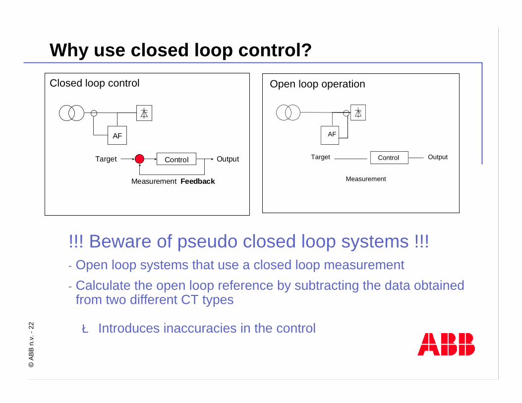
Why use closed loop control?
Control
AF
Target
Measurement Feedback
Output
Open loop operation
Control
AF
Target
Measurement
Output
Closed loop control
!!! Beware of pseudo closed loop systems !!!- Open loop systems that use a closed loop measurement- Calculate the open loop reference by subtracting the data obtainedfrom two different CT types
è Introduces inaccuracies in the control
Open loop operation

©AB
B n.
v. -
23
Why use closed loop control?
§ Directly measure and controlharmonic current flowing to network§ No risk of wrong THDI calculation§ Can verify harmonic according to
regulation directly§ Simple CT connection § Normal CT X/5A class 1 is sufficient§ Easy for future harmonic load
extensions§ Better accuracy & safety§ Appropriate for Local & Global
compensation
Open loop operationTHDI = ? unknownTotal loads = ? UnknownPass/fail regulation = ? Unknown
Accuracy drop !Future extent ion =?
VFD VFD VFD VFDVFDAF?
Other loads
spare
Control point
CT CT CT CTCT:x/1A
SCT
Closed loop controlDirectly control & measure THDI and total
load current then compensate
Future extent ion = easy
VFD VFD VFD VFDVFDPQF
Other loads
spare
CT : x/5A
Control point
©AB
B n.
v. -
24
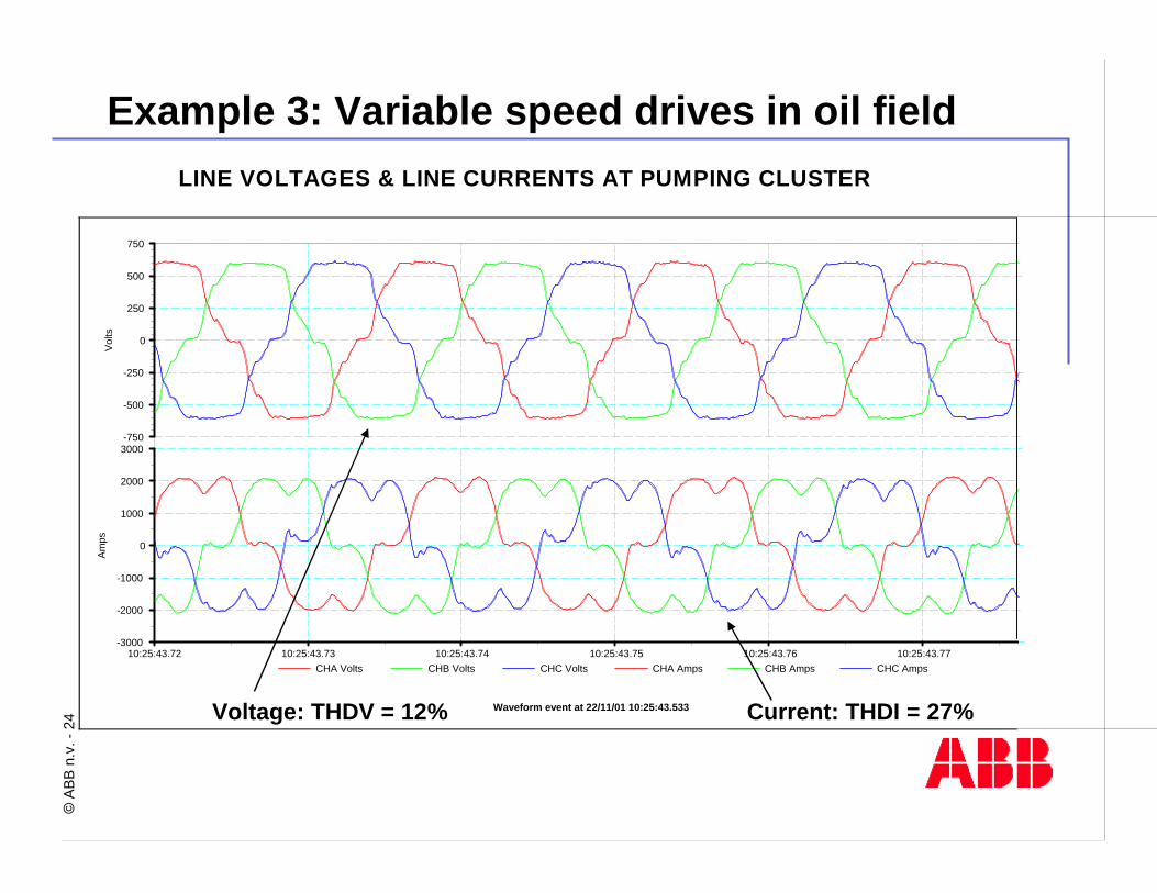
Example 3: Variable speed drives in oil fieldLINE VOLTAGES & LINE CURRENTS AT PUMPING CLUSTER
Waveform event at 22/11/01 10:25:43.533
CHA Volts CHB Volts CHC Volts CHA Amps CHB Amps CHC Amps
Vol
tsA
mps
10:25:43.72 10:25:43.73 10:25:43.74 10:25:43.75 10:25:43.76 10:25:43.77
-750
-500
-250
0
250
500
750
-3000
-2000
-1000
0
1000
2000
3000
Voltage: THDV = 12% Current: THDI = 27%
©AB
B n.
v. -
25
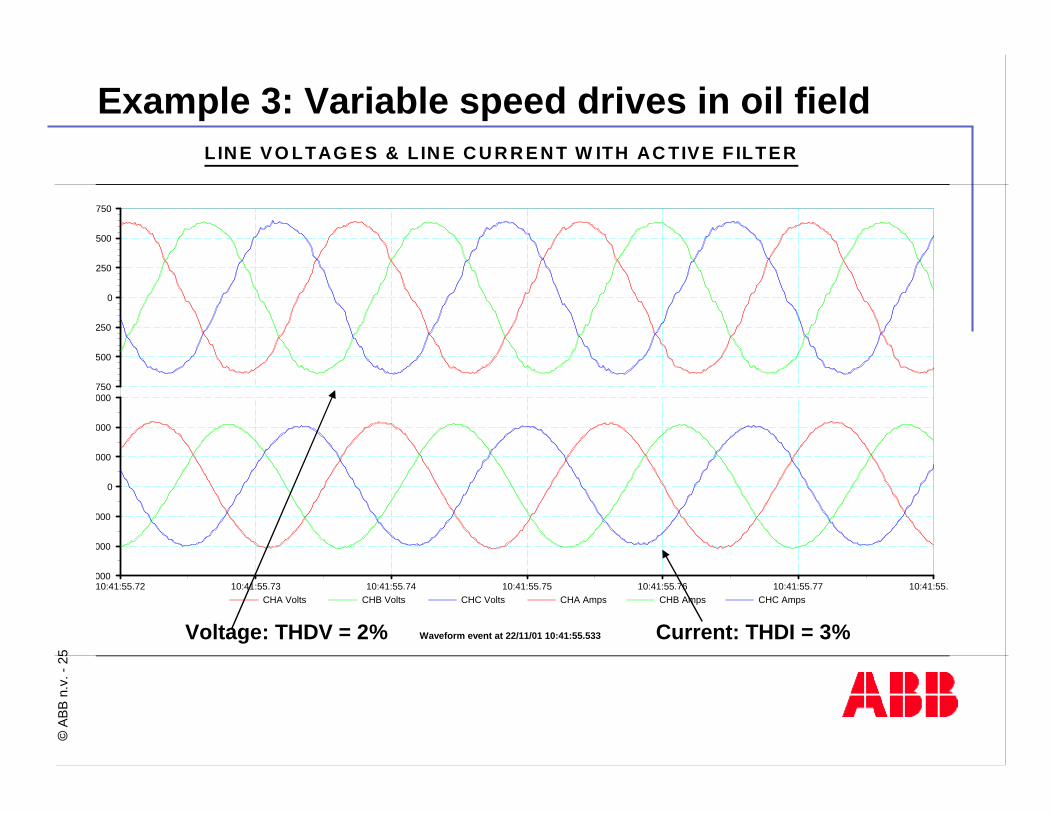
Example 3: Variable speed drives in oil fieldLIN E VO LTAG E S & L IN E C U R R E N T W ITH AC TIVE F ILTER
Waveform event at 22/11/01 10:41:55.533
CHA Volts CHB Volts CHC Volts CHA Amps CHB Amps CHC Amps 10:41:55.72 10:41:55.73 10:41:55.74 10:41:55.75 10:41:55.76 10:41:55.77 10:41:55.78
-750
-500
-250
0
250
500
750
-3000
-2000
-1000
0
1000
2000
3000
Voltage: THDV = 2% Current: THDI = 3%
©AB
B n.
v. -
26
Why load balancing/reactive power?
n To further improve the Power Quality of the network
n To have stepless reactive power available in sensitive networks (e.g. hospital environment)
n To have both inductive and capacitive reactive power available
n To avoid penalties of the utility
n To unload, increase life, of transformers
n To reduce fundamental current in the neutral due to unbalance loadsbetween line and neutral
n To reduce voltage build-up in neutral conductor w.r.t. ground

©AB
B n.
v. -
27
Example 4: Load balancing example
L1: 49.1 Arms
L2: 5.3 Arms
L3: 5.1 ArmsN: 44.1 Arms
N: 3.5 Arms
L1: 19.6 Arms
L2: 19.4 Arms
L3: 19.5 Arms

©AB
B n.
v. -
28
n 3-wire and 4-wire versions available in a wide voltage and current rangeè Suitable for small applications (e.g. 30 A, 45A, 60 A)è Suitable for large applications (e.g. 1800 A and higher)
n Does not get affected by changes in network impedanceE.g. Transformer paralleling, switch to backup generatorè Always perfect filtering results
n Uses an active unoverloadable technology that creates with high precision the filter harmonicsè Keeps running at nominal rating and informs customer of this
n Has a modular design, upgradeable on siteè 3-wire units: up to 8 units 4-wire units: up to 4 unitsè 3-wire units: units of different sizes may be combined
… It offers best performance on all networks and can grow with your needs!
Why use the PQF range of Active Filters (2)?

©AB
B n.
v. -
29
Why use the PQF range of Active Filters (3)?
n Auto restart functionality after power outage
n Remote control functionality through user programmable digital inputs
n 6 user programmable digital output contacts for filteroperation monitoring
n Modbus RTU communication capability
n Alarm contact with normal open and normal closed connection
n Low loss control system (e.g. 500 W to 2.8 kW for 100 A unit at 400V)
n Main and auxilary settings functionality
n Functions with standard class CTs
n Optical link between different modules for maximum isolation
n Reinforced output filters for certain models as standard
n Manufactured under ABB quality control guidelines
…because it is designed with the customer in mind!

©AB
B n.
v. -
30
Why use the PQF range of Active Filters (4)?…because it has an excellent user interface offeringextensive network analysis tools!n Standard provided with each filter
n Easy setup of the active filter
n Three phase network analyserè Numerical dataè Spectraè Time domain waveformsof all important electric parameters
n Filter status analysis toolsè Filter load indicationè Event log including fault analysis with time stampè Temperature sensor indications
n Connection point for all customer control and monitoring I/O

©AB
B n.
v. -
31
n Higher protection degree for certain models (IP41)
n External temperature probes
n RS232 - RS485 converter for Modbus communication
n Base frame
n Top cable entry options
n Printer
n Reinforced output filters for DC drive loads
n PQF-Link software for programming and monitoring the filter from a PC
Why use the PQF range of Active Filters (5)?…because it can be equipped with the options you need!

©AB
B n.
v. -
32
Where are the PQF active filters used?
Roller tablesRoller tables
CranesCranes OffshoreOffshore
WindersWinders
Paper machinePaper machine
Debarking drumsDebarking drums
Ski liftsSki lifts
PropulsionPropulsionCentrifugesCentrifuges DecantersDecanters
KilnsKilns CompressorsCompressors
…everywhere where Power Quality is at stake!!!
Hotels, banks, computing centres
Hotels, banks, computing centres

©AB
B n.
v. -
33
Example 5: Unbalanced load filteringLo
ad s
ide
curr
ents
[200
A/d
iv]
L3
L2
L1
Time [5ms/div]-1200
-1000
-800
-600
-400
-200
0
200
400
600
800
1000
1200
0 5 10 15 20 25 30 35 40 45 50 55 60 65 70 75 80

©AB
B n.
v. -
34
Example 5: Unbalanced load filtering
Supp
ly s
ide
curr
ents
[200
A/d
iv]
L3
L2
L1
Time [5ms/div]-1200
-1000
-800
-600
-400
-200
0
200
400
600
800
1000
1200
0 5 10 15 20 25 30 35 40 45 50 55 60 65 70 75 80

©AB
B n.
v. -
35
Example 6: Neutral protection overload
Protection
Ith (L): 100ARMS
N: 65-80% * Ith
MV LV
PQFT
L1 (R)L2 (Y)
L3 (B)N
NL Loads:- Fluor. light - PCs- ...
NL Loads:- Fluor. light - PCs- ...
NL Loads:- Fluor. light - PCs- ...

©AB
B n.
v. -
36
Example 6: Neutral protection overload
n H3 in neutral with and without filterWithout filter:
- IH3 ≈ 150 ARMS
With filter:
- IH3 ≈ 0 ARMS
Time [10 ms/div]
I [100 A/div]
I [100 A/div] Without filter
With filter

©AB
B n.
v. -
37
Example 7: Bank building compensation

©AB
B n.
v. -
38
Example 7: Bank building compensation
-400
-300
-200
-100
0
100
200
300
400
0.0
2.5
5.0
7.5
10.0
12.5
15.0
17.5
20.0
mSec
Volts
-400
-300
-200
-100
0
100
200
300
400
0.0
2.5
5.0
7.5
10.0
12.5
15.0
17.5
20.0
mSec
Volts
UPS output voltage
without compensationUPS output voltage
with compensation
THDv = 8.4% THDv = 4.7%
Filter running at nominal (full) load

©AB
B n.
v. -
39
Conclusions
n ABB- has a complete range of active filters- has a vast amount of experience in the active filter field
n ABB active filters:- have extremely high filtering efficiency- can filter up to a very high order- allow for reactive power compensation and loadbalancing (between lines or/and between line & neutral)
- are designed with the customer in mind
©AB
B n.
v. -
40
Conclusions
Talk to ABB for expert advice on solving your Power Quality problems
ABB Active Filters,
when Power Quality matters!
