power management using lenovo ups power protector (upp ...lenovopress.com/lp1076.pdf · lenovo ups...
TRANSCRIPT
Last Update: January 2020
Front cover
Power Management Using Lenovo UPS Power Protector (UPP) and UPS Power Manager (UPM)
Explains the importance of power-chain protection in the data center
Introduces the Lenovo UPP and UPM power management software for power management and protection
Provides details on the capabilities and benefits of using UPP and UPM for power outage action plans
Discusses the differences between UPP and UPM and when and why to implement one over the other
Rani Doughty
Matt Archibald
2 Power Management Using Lenovo UPS Power Protector (UPP) and UPS Power Manager (UPM)
Abstract
A brief or extended interruption of power from the electric utility company can cause significant or permanent damage for any data center equipment that is unprotected during a power event. The outcome can become costly for companies due to potential loss of data and equipment down-time. This is why an uninterruptible power supply (UPS) is a critical component of a data center’s infrastructure to protect and safe guard against power outages.
This paper discusses how to install and use two Lenovo® UPS software offerings:
� Lenovo UPS Power Protector (UPP)� Lenovo UPS Power Manager (UPM)
This paper is based on UPM version 1.54 and 1.57 and UPP version 1.57.
The Lenovo UPP software product can help manage and protect single nodes over a local network while the Lenovo UPM software is an enterprise solution that can manage and protect many nodes across multiple data centers from the damage caused by power interruptions and outages.
This paper is written for those looking to learn about Lenovo’s solution to hardware and data protection and how to create action plans to minimize the risk of data loss and downtime during power interruptions and extended outages. It assumes the reader has basic knowledge of power, PDUs and UPS hardware and solutions.
At Lenovo Press, we bring together experts to produce technical publications around topics of importance to you, providing information and best practices for using Lenovo products and solutions to solve IT challenges. See a list of our most recent publications at our web site:
http://lenovopress.com
Contents
Introduction . . . . . . . . . . . . . . . . . . . . . . . . . . . . . . . . . . . . . . . . . . . . . . . . . . . . . . . . . . . . . . 3The importance of power-chain protection in the data center . . . . . . . . . . . . . . . . . . . . . . . . 4Comparing UPM and UPP . . . . . . . . . . . . . . . . . . . . . . . . . . . . . . . . . . . . . . . . . . . . . . . . . . . 8UPS and PDU portfolio overview . . . . . . . . . . . . . . . . . . . . . . . . . . . . . . . . . . . . . . . . . . . . . 12UPS Power Protection (UPP). . . . . . . . . . . . . . . . . . . . . . . . . . . . . . . . . . . . . . . . . . . . . . . . 16UPS Power Manager (UPM) . . . . . . . . . . . . . . . . . . . . . . . . . . . . . . . . . . . . . . . . . . . . . . . . 24Strategies for managing and protecting virtual environments . . . . . . . . . . . . . . . . . . . . . . . 55Summary . . . . . . . . . . . . . . . . . . . . . . . . . . . . . . . . . . . . . . . . . . . . . . . . . . . . . . . . . . . . . . . 61Change history . . . . . . . . . . . . . . . . . . . . . . . . . . . . . . . . . . . . . . . . . . . . . . . . . . . . . . . . . . . 62About the authors. . . . . . . . . . . . . . . . . . . . . . . . . . . . . . . . . . . . . . . . . . . . . . . . . . . . . . . . . 62Notices . . . . . . . . . . . . . . . . . . . . . . . . . . . . . . . . . . . . . . . . . . . . . . . . . . . . . . . . . . . . . . . . . 63Trademarks . . . . . . . . . . . . . . . . . . . . . . . . . . . . . . . . . . . . . . . . . . . . . . . . . . . . . . . . . . . . . 64

Introduction
Data centers today are being dramatically transformed from being monolithic rigid facilities to limber, scalable operations where companies rely on hyperconverged infrastructures and more powerful IT equipment then ever before. These transformations are happening because of the flexible new capabilities derived from software-defined technologies such as toolings, virtualization and abstraction.
IT organizations are increasingly leveraging software-defined data centers to reduce infrastructure cost, add speed and agility to recover from outages and to streamline managing and scaling up hardware and software resources. At the same time a relatively new approach is transforming data center management. It is called software-defined power.
Power events are dangerous, common occurrences, capable of damaging valuable equipment in data centers, bringing production to a halt, and even loss of data if proper power management and protection is not in place. This makes planning and deploying a robust, well-designed power management and protection solution absolutely vital to the safety of equipment and success of a data center.
Lenovo offers two power management software options to manage and protect the power in a data center. These include the Lenovo UPS Power Protection (UPP) and the Lenovo UPS Power Manager (UPM) software. The following discusses the benefits of each software in more detail.
The Lenovo UPS Power Protection (UPP) software is a free offering that can be used to manage smaller installations to facilitate automatic, graceful shutdown of computers, servers, and network devices that are powered by a UPS, which saves all work-in-progress and ensures data integrity when a power event occurs.
The UPP provides the following benefits:
� Helps avoid data loss by gracefully shutting down computers and virtual machines or servers that are powered by a UPS during an extended power outage
� Keeps servers running smoothly by automatically identifying hang-ups and rebooting the machine by using a watchdog capability
� Provides redundancy capability for dual-cord servers
� An easy-to-use web browser interface
� Communicates with the protected device directly (via USB or serial) or through the network (via NMC)
The Lenovo UPS Power Manager (UPM), when coupled with network-enabled UPSs and PDUs with TCP/IP interfaces, is a powerful environmental protection offering that provides all of the tools necessary to address monitoring and managing both physical and virtual environments and taking action when necessary to protect the hardware and the integrity of the data when a power event occurs.
UPM provides the following benefits:
� Discovers and supervises UPSs, PDUs, and Lenovo UPS Power Protection (UPP) installations.
� Supervises remote servers hosting UPP, and network enabled UPS units and PDUs.
� Provides advanced management feature (mass configuration and mass upload) with Lenovo UPS NMCs.
© Copyright Lenovo 2020. All rights reserved. 3

� Provides local computer graceful shutdown through network or local connectivity, such as via a USB or RS-232 port.
� Provides an agentless method for directly managing and controlling VMware hypervisors through the VMware vCenter management platform.
� Provides centralized management of Lenovo UPP applications running on virtualized servers other than VMware vCenter (such as Microsoft Hyper-V hypervisor or Citrix Xen).
� Remotely configure, manage and update devices that are connected on the network. This means an entire network of devices can be monitored and managed with UPM.
� Significantly reduce the cost and complexity of rolling out new commands, features and functions by executing mass management card firmware upgrades over the network.
� Provide load shedding to reduce power consumption of servers to extend battery runtime during a power outage.
� The ability to suspend non-critical virtual machines, consolidate critical virtual machines and gracefully shut down unused servers to extend UPS battery runtime for critical machines.
� Automate disaster avoidance with a planned migration application, such as VMware Site Recovery Manager and Microsoft Live Migration to a disaster recovery (DR) site.
� Integrate the software seamlessly into popular virtualization infrastructures, including VMware ESXi, Microsoft Hyper-V and Citrix XenServer, or can be installed as a standalone application.
� UPM software is compatible with most devices that support a network interface, including non-Lenovo hardware.
� The software can be downloaded from the Lenovo website and can be used on any Windows system.
� Up to ten power devices (also referred to as nodes) can be managed with UPM at no cost. If more than ten power devices will be managed then a Silver license can be purchased. A Silver license supports between 11-100 nodes. If more than 100 nodes will be managed then a Gold license can be purchased. A Gold license will support between 101-500 nodes. Note, a device/node is defined as a PDU or UPS that has been discovered and is being monitored with UPM.
The importance of power-chain protection in the data center
Data centers are the hub of modern business. Customers have aligned their business around high-availability applications and scalable, on-demand resource pools. It is critical that data and applications are available at all times and that the costs for delivering and supporting those resources are minimized.
Lenovo UPSs provide IT equipment with clean, uninterrupted power to help ensure that critical applications stay running. Lenovo UPSs are mounted as close to the supported IT systems as possible to provide the highest possible level of reliability and uptime to the business.
A typical medium-to-large enterprise power chain flow is shown in Figure 1. Traditionally, the IT equipment in the data center space is supported by one or a few large UPS systems. Power is distributed from the output of the UPS to IT equipment through power distribution panels, otherwise known as circuit panels, and then distributed further within the IT rack through rack PDUs.
4 Power Management Using Lenovo UPS Power Protector (UPP) and UPS Power Manager (UPM)

Figure 1 Data center power chain topology (medium-to-large enterprise installation)
These larger UPSs have built-in protection and regulation subsystems that equate to over 99% uptime and availability and greater than 95% efficiency. The risk in this topology comes downstream from the UPS. If there is a power fault after the UPS, all IT systems connected to the circuit on which the fault occurred are exposed to the fault condition.
In smaller installations, the UPS is typically located closer to the IT systems it is supporting. Figure 2 shows a topology where the IT systems are directly connected to the UPS and the UPS is supplied directly from the power distribution panels (circuit boards).
Figure 2 Data center power topology (smaller installations)
Moving the UPS closer to the supported IT systems decreases the risk of power line disturbances downstream of the UPS affecting other IT systems because typically fewer IT systems are connected to the smaller UPS units.
Lenovo UPS units come in both tower and rack form factors. Tower variations of the UPS units are best suited for small IT installations and supporting tower servers. Rack UPS units can be mounted in Lenovo IT racks along with IT systems like servers, storage enclosures, and networking devices.
In distributed and retail environments, there is typically no power protection in the form of battery backup and/or power quality monitoring. Adding a Lenovo UPS to the deployed server solution will provide the highest level of reliability to the solution.
The benefits of the UPS are further extended when adding UPS Power Protector (UPP) or the UPS Power Manager (UPM). The UPP and UPM software packages provide more capability to monitor and ultimately manage the physical and virtual environment, bringing in a new level of software defined power for the data center.
5

For more information of UPP and UPM and the benefits each brings to the IT environment, see section “UPS Power Protection (UPP)” on page 16 and “UPS Power Manager (UPM)” on page 24.
Lenovo UPSs all provide pure sine wave output voltage. This is important in that the power being delivered to the IT systems is of the highest quality. The Lenovo UPSs are highly efficient, with typical run-time efficiencies of greater than 94% when in line-interactive mode and greater than 75% efficiency when in double-conversion mode.
Lenovo UPSs have input voltage sensing to guarantee an output voltage at the user programmed output level. One of the biggest benefits of input voltage sensing is when any power line disturbance is detected on the input, the UPS quickly changes to double conversion mode to arrest the disturbance and provide clean, continuous power to the IT systems.
Value proposition of UPP and UPM
IT professionals routinely face unplanned and lengthy power outages and must manage business continuity in multiple locations. No matter how big the customer or solution deployment, downtime is expensive. From SMBs to Enterprise customers, running data center applications of all sizes and ensuring business continuity, is always a challenge. However, creating a disaster recovery plan can reduce downtime impact. IT managers can do this by deploying UPP in smaller local installations and UPM in larger network distributed installations.
UPP provides data center administrators the tools necessary to implement local graceful shutdowns of host servers in the event of a power incident, helping to ensure data integrity during a total power outage.
UPM provides data center administrators the tools necessary to implement a flexible and scalable disaster avoidance plan to mitigate the impact of a disaster recovery by:
� Minimizing data loss� Minimizing recovery time� Maximizing data integrity� Maximizing run time of critical hosts and VMs
Figure 3 on page 7 shows critical events that can happen in a data center and the different planning options available with UPM to maintain data integrity with graceful shutdowns and maximize the up time of critical machines by shedding non-critical work loads or moving them off-site with VMware Site Recovery Manager (SRM). These capabilities lead to minimizing data loss and recovery time.
6 Power Management Using Lenovo UPS Power Protector (UPP) and UPS Power Manager (UPM)

Figure 3 Disaster avoidance planning with UPM and VMware
Implementing UPM can also have CapEx (capital expenses) and CapOp (capital operation) benefits such as the following:
� CapEx savings with UPM:
– Less cost up front: This is because UPM can perform load shedding and power capping of non-critical VMs and hosts, which means less external battery modules (EBMs) are required when a critical power event occurs. This equates to less cost up front for a UPS solution.
– Space and rack consolidation: Less hardware up front means a reduction of physical infrastructure cost and space. For instance, as shown in Figure 4 on page 8 using a scenario of 3 racks, 6kVA and a half hour of runtime, the end user can use UPM to save one EBM per rack, while still yielding a half hour of runtime by using UPM’s load shedding and power capping features. The savings are also realized by reducing the number of batteries needing replacement during the UPSs lifespan. The end user can reduce CapEx spend and total cost of ownership when swapping out battery modules for UPM.
Critical Event Disaster Avoidance Plan
Input Power Lost
Redundancy Lost
Power Protection Lost
High Temperatures
Keep Workload At Current Data
Center
Shed Non-critical Workload
Action: Start Load Shedding
Action: Power Cap Servers
Power Cap Servers
Remaining Power
Sufficient?
Yes
No Power Cap Remaining
ServersNo
Yes
Yes
No
No
No
End
Yes
Action: Start SRM Migration
7

Figure 4 UPM CapEx saving example
� CapOp savings with UPM:
– Power and cooling efficiencies that cuts operating cost: Leveraging UPM with the appropriate disaster recovery plan can cut data center operating costs. For example use UPM integrated load shedding to sequentially shutdown unused servers. This will enable you to double the backup run time utilizing current backup infrastructure.
– Environmental load shedding and syncing priority data and applications to recovery sites will cut backup and data retrieval costs.
Comparing UPM and UPP
Lenovo offers two software tools for power management and protection:
� Lenovo UPS Power Protector (UPP)
� Lenovo UPS Power Manager (UPM)
Lenovo UPP is protection software that gracefully shuts down local computers and servers powered by Lenovo UPSs in the event of a power outage. UPP is a free piece of software that can be downloaded from the Lenovo support site:
http://datacentersupport.lenovo.com/us/en/solutions/lnvo-ups-mgmt
Lenovo UPM is an environmental device supervision tool for IT environments. UPM delivers a global view across the network from any PC with an internet browser. The software is versatile in that it supports any device with a network interface, including environment sensors, PDUs, and UPSs. Lenovo UPM provides a platform for policy-based management of groups of servers, centralization of alarms, and maintain event logs for preventative maintenance of the entire infrastructure equipment install base.
��������
�������������
8 Power Management Using Lenovo UPS Power Protector (UPP) and UPS Power Manager (UPM)

Lenovo UPM has a free license (Basic) and two paid licenses (Silver and Gold) available that offer different features. The UPM can also be downloaded from the same Lenovo support site as the UPP software:
http://datacentersupport.lenovo.com/us/en/solutions/lnvo-ups-mgmt
The following section discusses each version and what they offer.
UPP and UPM features and software licensing
UPM is free to use for up to 10 devices (UPSs or PDUs). For between 11 and 100 devices a paid Silver license is needed. For between 101 and 500 devices, a paid Gold license is needed.
Table 1 shows the part numbers for each UPM software version. The license can be upgraded later without reinstallation of the software. To apply a license to the software, refer to “Applying a Silver or Gold license” on page 33.
Table 1 Part numbers for UPM
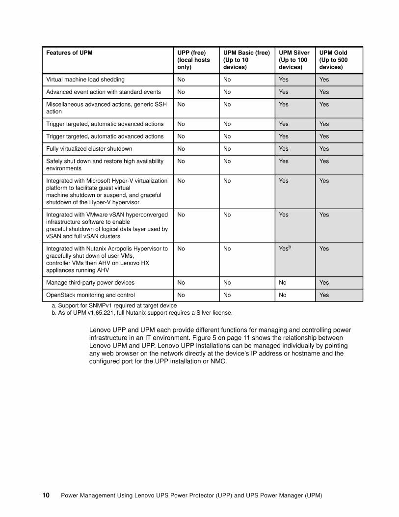
Not all features are included in the free and Silver versions of the software. Table 2 on page 9 shows the UPM licenses and features for each license.
Table 2 UPP and UPM software licenses and features
Note: A device refers to a UPS or a PDU. This means a free license will support up to 10 UPS or PDUs. A silver license key will support 11-100 UPS units or PDUs. A gold license will support 101-500 UPS units or PDUs.
Part Number Description
None Basic (free) UPM software (1-10 devices can be managed)
00YE464 Silver key license (11-100 devices can be managed)
00YE465 Golden key license (101-500 devices can be managed)
Features of UPM UPP (free)(local hosts only)
UPM Basic (free)(Up to 10 devices)
UPM Silver(Up to 100 devices)
UPM Gold(Up to 500 devices)
Identify and monitor third-party power devices Yes Yes Yes Yes
Shut down server and host without crashing Yes Yes Yes Yes
Configuration policy Yes Yes Yes Yes
Control rack PDUs (on, off and reboot sections or outlets)a
Yes Yes Yes Yes
Plug-in for VMware vCenter No Yes Yes Yes
Enter and exit maintenance mode No Yes Yes Yes
Shut down virtual hosts (e.g. VMware ESXi) No Yes Yes Yes
Shutdown storage No Yes Yes Yes
Shut down specific virtual machines No No Yes Yes
Migrate virtual machines to targeted hosts No No Yes Yes
9
Lenovo UPP and UPM each provide different functions for managing and controlling power infrastructure in an IT environment. Figure 5 on page 11 shows the relationship between Lenovo UPM and UPP. Lenovo UPP installations can be managed individually by pointing any web browser on the network directly at the device’s IP address or hostname and the configured port for the UPP installation or NMC.
Virtual machine load shedding No No Yes Yes
Advanced event action with standard events No No Yes Yes
Miscellaneous advanced actions, generic SSH action
No No Yes Yes
Trigger targeted, automatic advanced actions No No Yes Yes
Trigger targeted, automatic advanced actions No No Yes Yes
Fully virtualized cluster shutdown No No Yes Yes
Safely shut down and restore high availability environments
No No Yes Yes
Integrated with Microsoft Hyper-V virtualization platform to facilitate guest virtualmachine shutdown or suspend, and graceful shutdown of the Hyper-V hypervisor
No No Yes Yes
Integrated with VMware vSAN hyperconverged infrastructure software to enablegraceful shutdown of logical data layer used by vSAN and full vSAN clusters
No No Yes Yes
Integrated with Nutanix Acropolis Hypervisor to gracefully shut down of user VMs,controller VMs then AHV on Lenovo HX appliances running AHV
No No Yesb Yes
Manage third-party power devices No No No Yes
OpenStack monitoring and control No No No Yes
a. Support for SNMPv1 required at target deviceb. As of UPM v1.65.221, full Nutanix support requires a Silver license.
Features of UPM UPP (free)(local hosts only)
UPM Basic (free)(Up to 10 devices)
UPM Silver(Up to 100 devices)
UPM Gold(Up to 500 devices)
10 Power Management Using Lenovo UPS Power Protector (UPP) and UPS Power Manager (UPM)

Figure 5 Sample environment showing Lenovo UPM and UPP relationship
UPP can be remotely managed, configured, and updated using Lenovo UPM supervisory software. Using Lenovo UPM, a user can perform mass configurations and mass updates of Lenovo UPP applications. UPM can also remotely perform the following:
� Display a Lenovo UPP configuration
� Configure a single Lenovo UPP
� Synchronize multiple Lenovo UPP configurations
� Trigger Lenovo UPP upgrades
UPP and UPM can be downloaded from the following link:
http://datacentersupport.lenovo.com/us/en/solutions/lnvo-ups-mgmt
This paper focuses on managing environments with UPM. For a brief discussion of the features and functions of UPP, refer to “UPS Power Protection (UPP)” on page 16.
For additional information on UPP, see the Product Guides for each Rack or Tower UPS units, available from:
http://lenovopress.com/servers/options/ups
������������ � �����������
����������������� � ������ �� ���
����������
��������� ���������
��������!�����
���������
��������!�����
���������
��������!�����
���������
��������!�����
���������
��������!�����
�����������"#
ThinkSystem$"% ����&�
ThinkSystem$"% ����&�
ThinkSystem
ThinkSystem
ThinkSystem
���������������������������������ThinkSystem
���������������������������������������ThinkSystem
��������!�����
��"�����%��Server �!�6
$"% ���#��� �����%��Server �016
��������%��Server �!�6
11

UPS and PDU portfolio overview
UPM can be used free of charge for up to 10 devices. A license to manage additional hardware is required. Refer to Table 2, “UPP and UPM software licenses and features” on page 9 for additional information on licensing and determining the number of managed devices supported.
Table 3 lists the Lenovo UPS and Extended Battery Module (EBM) portfolio.
Table 3 Lenovo UPS portfolio
Note: A device (sometimes referred to as a node) refers to a UPS or PDU that is being managed by UPM.
Connectivity: UPP can be connected directly to a UPS via USB or serial. For UPM to function, a Network Management Card (NMC) needs to be installed in the UPS.
The NMC is optional for 55951AX, 55951KX, 55952AX, 55952KX, 55941AX, 55941KX, 55942AX, 55942KX, and 55942BX. All other UPS units ship standard with the NMC.
MTM Description Input Line Cord NMC Outlets
Tower Models
55951AX 1kVA Tower UPS (110V) 5-15P Optional 8x 5-15R
55951KX 1kVA Tower UPS (230V) Selectable Optional 8x C13
55952AX 1.5kVA Tower UPS (110V) 5-15P Optional 8x 5-15R
55952KX 1.5kVA Tower UPS (230V) Selectable Optional 8x C13
Rack Mount or Tower Models
55941AX 1.5kVA R/T UPS (100V/120V) 5-15P Optional 8x 5-15R
55941KX 1.5kVA R/T UPS (200V-230V) Selectable Optional 8x C13
55942AX 2.2kVA R/T UPS (100V/120V) 5-20P Optional 8x 5-20R
55942KX 2.2kVA R/T UPS (200V -230V) Selectable Optional 8x C13, 1x C19
55942BX 1.5kVA/2.2kVA EBM Not applicable Not applic N/A
55943AX 3kVA R/T UPS (100V/120V) L5-30P Yes 6x 5-20R, 1x L5-30R
55943KX 3kVA R/T UPS (200V-230V) Selectable Yes 8x C13, 1x C19
55943BX 3kVA EBM Not applicable Not applic N/A
55945KX 5kVA R/T UPS (200V-230V) Selectable Yes 8x C13, 2x C19
55946KX 6kVA R/T UPS (200V-230V) Hardwired Yes 8x C13, 2x C19
55946BX 5kVA/6kVA EBM Not applicable Not applic N/A
55948KX 8kVA R/T UPS (200V-230V) Hardwired Yes 4x C19
55948PX 8kVA 3 ph MBP (200V-230V) Hardwired Yes 4x C19
55949KX 11kVA R/T UPS (200V-230V) Hardwired Yes 4x C19
12 Power Management Using Lenovo UPS Power Protector (UPP) and UPS Power Manager (UPM)

Table 4 Lenovo UPS portfolio available in ASEAN, HTK, INDIA, and China
For additional information on the Lenovo UPS portfolio and technical specifications, refer to the following UPS Technical Planning Guide:
http://www.lenovo.com/images/products/system-x/pdfs/power-config/system_x_ups_.pdf
Table 5 Lenovo PDU portfolio - North America
55949PX 11kVA 3 ph MBP (200V-230V) Hardwired Yes 4x C19
55949BX 8kVA/11KVA EBM Not applicable Not applic N/A
MTM Description Outlets
Rack Mount or Tower Models
55943KT RT3kVA 2U Standard UPS (200-230V) 2x C13, 2x GB, 1x C19
55943LT RT3kVA 2U Long Backup UPS (200-230V) 2x C13, 2x GB, 1x C19
55946KT RT6kVA 5U UPS (200-230V) 2x C13 outlets, 1x Terminal Block
5594XKT RT10kVA 5U UPS (200-230VAC) 2x C13 outlets, 1x Terminal Block
MTM Description Input Line Cord NMC Outlets
Part number
Description Voltage (V) Number / type of outlets
Lenovo Basic PDUs (non-monitored, non-switched)a
00YE443 DPI Universal Rack PDU 100 - 127 V / 200 - 240 Vb
(7) C13
39Y8905 DPI NEMA Rack PDU 100 - 127 V (6) 5-15
39Y8938 Front End PDU 100 - 127 V (3) C19
39Y8939 Front End PDU 200 - 240 V (3) C19
39Y8940 Front End PDU 200 - 240 V (3) C19
39Y8941 DPI Enterprise – C13 PDU 200 - 240 V (12) C13
39Y8948 DPI Enterprise – C19 PDU 200 - 240 V (6) C19
39Y8923 DPI Enterprise – C19 PDU 208 V (6) C19
71762NX Ultra Density Enterprise PDU 200 - 240 V (9) C19, (3) C13
71763NU Ultra Density Enterprise PDU 208 V (9) C19, (3) C13
00YJ776 0U 36 C13/6 C19 30A 1 Phase PDU 200 - 240 V (6) C19, (36) C13
00YJ779 0U 21 C13/12 C19 60A 3 Phase PDU 200 - 240 V (12) C19, (21) C13
44T0966 1U Higher Voltage DC PDU 240 - 380 VDC (6) Rong Feng RF-203P
Lenovo Monitored PDUs (non-switched)
39M2816 DPI Enterprise PDU+ C13 200 - 240 V (12) C13
44X3193 DPI Enterprise PDU+ C13 208 V (12) C13
13

For additional information on the Lenovo North American PDU portfolio and technical specifications, refer to the following PDU Technical Planning Guide:
http://www.lenovo.com/images/products/system-x/pdfs/power-config/system_x_pdu_na_tr.pdf
Table 6 Lenovo PDU portfolio - International
Lenovo Switched and Monitored PDUs
46M4004 1U 12 C13 Switched and Monitored PDU 200 - 240 V (12) C13
46M4005 1U 12 C13 Switched and Monitored PDU 208 V (12)C13
46M4002 1U 9 C19 / 3 C13 Switched and Monitored PDU 200 - 240 V (9) C19, (3) C13
46M4003 1U 9 C19 / 3 C13 Switched and Monitored PDU 208 V (9) C19, (3) C13
00YJ781 0U 20 C13/4 C19 Switched and Monitored 30A 1 Phase PDU 200 - 240 V (4) C19, (20) C13
00YJ783 0U 12 C13/12 C19 Switched and Monitored 60A 3 Phase PDU 200 - 240 V (12) C19, (12) C13
a. Note: These are non-monitored PDUs. UPM requires monitoring capabilities to monitor a device.b. Voltage is dependent on line cord selection. Refer to the below link for line cord options.
Part number
Description Voltage (V) Number / type of outlets
Part number
Description Voltage (V) Number / type of outlets
Lenovo International Basic PDUs (non-monitored, non-switched)a
00YE443 DPI Universal Rack PDU 100 - 127 V / 200 - 240 Vb
(7) C13
39Y8934 Front end PDU 220 - 240 V (3) C19
39Y8935 Front end PDU 220 - 240 V (3) C19
39Y8936 Front end PDU 230 - 2 40 V (3) C19
39Y8937 Front end PDU 220 V (3) C19
39Y8941 DPI Enterprise C13 PDU 220 - 240 V (12) C13
39Y8948 DPI Enterprise C19 PDU 220 - 240 V380 - 415 Vc
(6) C19
71762NX Ultra Density Enterprise PDU 220 - 240 V380 - 415 Vc
(9) C19, (3) C13
00YJ777 0U 36 C13/6 C19 32A 1 Phase PDU 200 - 240 V (6) C19, (36) C13
00YJ778 0U 21 C13/12 C19 32A 3 Phase PDU 200 - 240 V (12) C19, (21) C13
44T0966 1U Higher Voltage PDU 240 - 380V DC
(6) Rong Feng RF-203P
Lenovo Monitored PDUs (non-switched)
39M2816 DPI Enterprise C13 PDU 220 - 240 V (12) C13
Lenovo Switched and Monitored PDUs
14 Power Management Using Lenovo UPS Power Protector (UPP) and UPS Power Manager (UPM)
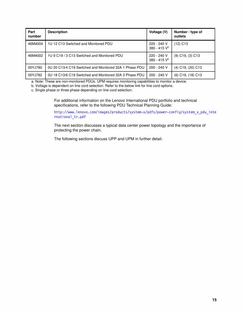
For additional information on the Lenovo International PDU portfolio and technical specifications, refer to the following PDU Technical Planning Guide:
http://www.lenovo.com/images/products/system-x/pdfs/power-config/system_x_pdu_international_tr.pdf
The next section discusses a typical data center power topology and the importance of protecting the power chain.
The following sections discuss UPP and UPM in further detail.
46M4004 1U 12 C13 Switched and Monitored PDU 220 - 240 V380 - 415 Vc
(12) C13
46M4002 1U 9 C19 / 3 C13 Switched and Monitored PDU 220 - 240 V380 - 415 Vc
(9) C19, (3) C13
00YJ780 0U 20 C13/4 C19 Switched and Monitored 32A 1 Phase PDU 200 - 240 V (4) C19, (20) C13
00YJ782 0U 18 C13/6 C19 Switched and Monitored 32A 3 Phase PDU 200 - 240 V (6) C19, (18) C13
a. Note: These are non-monitored PDUs. UPM requires monitoring capabilities to monitor a device.b. Voltage is dependent on line cord selection. Refer to the below link for line cord options.c. Single phase or three phase depending on line cord selection.
Part number
Description Voltage (V) Number / type of outlets
15

UPS Power Protection (UPP)
The Lenovo UPP software (Uninterruptible Power Supply Protector) addresses the events of extended power outages and provides an action plan. This section discusses in further detail the capabilities and action plans available with the UPP software.
Note: For information on UPM and its capabilities, refer to, “UPS Power Manager (UPM)” on page 24.
UPP offers the following features:
� UPS Power Protector software will gracefully shut down servers and computers that are powered by a Lenovo UPS in the event of an extended power outage.
� UPP can be remotely configured, managed and updated with UPM or managed on its own on each individual server.
� Helps avoid data loss by automatically gracefully shutting down virtual machines or servers that are powered by a Lenovo UPS during an extended power outage
� Keeps servers running smoothly by automatically identifying hang-ups and rebooting the machine by using a watchdog capability.
� An easy-to-use web browser interface that can be accessed remotely using a simple web browser. Access to the web interface can be secured through an SSL connection and can also be secured through a login and password.
� UPP compatibility with major virtualization platforms such as VMware vCenter Server, Citrix XenServer, Microsoft SCVMM, Red Hat and other Xen open source platforms, allowing users to view and manage their entire power system from a single dashboard.
� Communicates with the protected device directly (via USB or serial) or through the network via a network management card (NMC).
� An entire network of devices that are loaded with UPP software can be monitored and managed with UPS Power Manager.
Installation prerequisites
This section provides installation prerequisites for the following:
� Systems hosting UPP
� Systems that display the web-based graphical user interface (GUI)
� UPP support for virtualization platforms
Tip: Use UPP for locally managing and shutting down managed end points. Use UPM and UPP software together to provide an end-to-end power management solution across multiple racks and data centers.
16 Power Management Using Lenovo UPS Power Protector (UPP) and UPS Power Manager (UPM)

UPP supported operating systemsTable 7 shows the platform and operating system version compatibility matrix for UPP.
Table 7 UPP OS compatibility matrix
Operating System UPP (v1.57)
Microsoft Windows Server 2016 Yes
Microsoft Windows Server 2012 R2 Yes
Microsoft Windows Server 2012 Yes
Microsoft Windows Server 2011 Small Business Server and Home Server Not tested
Microsoft Windows Server 2008 R1, R2 Yes
Microsoft Windows Server 2008 Small Business Server Yes
Microsoft Hyper-V Server Core 2016 Yes
Microsoft Hyper-V Server Core 2012 R2 Yes
Microsoft Hyper-V Server Core 2012 Yes
Microsoft Hyper-V Server Core 2008 R2 Yes
Microsoft Windows 10 (All versions) Yes
Microsoft Windows 8.1 (All versions) Yes
Microsoft Windows 8 (All versions) Yes
Microsoft Windows 7 (All versions) Yes
Red Hat Enterprise Linux 7.4, 7.3 Yes
Red Hat Enterprise Linux 6.10 Yes
Red Hat Enterprise Linux 5.11, 5.10, 5.9 Not tested
Red Hat Fedora Core 28 Yes
SUSE Linux Enterprise Server 12 SP3 Yes
SUSE Linux Enterprise Server 11 SP4 Not tested
SUSE Linux Enterprise Server 10 SP4 Not tested
OpenSUSE 13.2, 13.1, 12.3 Not tested
Debian 9.4 Yes
Ubuntu 18.04 LTS Yes
Ubuntu 17.10 Yes
VMware ESXi 6.5 Not tested
VMware ESXi 6.0 U2 Not tested
VMware ESXi 5.5 U3 Not tested
Note: For better performance with multiple nodes, Lenovo recommends a Microsoft Windows Server OS. This is because the Microsoft Windows desktop versions have a limitation of 10 simultaneous network connections.
17

To avoid network or serial port access conflicts, do not install UPP on a machine that also hosts the following:
� UPM � Eaton Network Shutdown Module� Eaton Intelligent Power Manager (IPM)� Network Management Proxy� Personal Solution Pac� LanSafe and LanSafe Web View� Netwatch
UPP supported web browsersThe UPP graphical user interface can be accessed remotely using a simple web browser. Access to this interface can be secured through Secure Socket Layer (SSL) connection and is also secured through login and password.
The UPP web interface has been tested and is supported with the following web browsers:
� Google Chrome� Mozilla Firefox� Microsoft Internet Explorer 7+
Installing UPP
UPP can be downloaded at no charge from the following link:
http://datacentersupport.lenovo.com/us/en/solutions/lnvo-ups-mgmt
Note: For Windows installations, you must deselect the standby configuration of your operating system to be compliant with the UPP software. With the standby configuration checked your system is not protected. The standby power can be adjusted in the power and sleep settings of Windows.
Note: While IE 7 is supported, for better performance IE 9 and later is recommended. For optimal performance either Google Chrome or Firefox browsers should be used.
Note: UPP should not be installed on the same system running UPM. This is to avoid network and serial port conflicts.
18 Power Management Using Lenovo UPS Power Protector (UPP) and UPS Power Manager (UPM)

The steps to install UPP are as follows:
1. Download and launch the UPP installer. Figure 6 shows the welcome screen for the installer.
Figure 6 Lenovo UPP installation screen
2. Click the Next button, accept the license agreement and follow the prompts to install the software.
3. When the installation has successfully finished, the following screen will appear as shown in Figure 7.
Figure 7 Successful install
19

4. Click the Finish button. A login screen will be displayed as seen in Figure 8. The default login credentials are:
User ID: USERID Password: passw0rd (with a zero)
The first time you log in, you will be prompted to change the password.
Figure 8 Lenovo UPP login interface
5. A web browser is launched to the UPP web interface, Figure 9.
Figure 9 Lenovo UPP web interface
The next step is to discover the locally attached devices. For information on discovery and configurations, refer to “Discovering devices in UPM and UPP” on page 34.
The next section discusses the UPP graceful shutdown feature.
Local graceful shutdown with UPP
Along with monitoring capabilities (as described in “Introduction to monitoring with UPM and UPP” on page 37, UPP, can also be used to gracefully shutdown a local computer when connected to a UPS through either a network connection (Web/SNMP), USB port or RS232 serial port.
Setting up a local graceful shutdownA power source needs to be defined in the UPP interface for a graceful shutdown to be allowed. If a power source is not configured, UPP will continue to give a communication error if no power source has been defined.
Tip: If the browser does not open automatically, start a browser and go to https://127.0.0.1:4679
20 Power Management Using Lenovo UPS Power Protector (UPP) and UPS Power Manager (UPM)

To set a power source, click the Settings > Shutdown option from the left hand menu and then click Edit power source from the menu on the right side of the window as seen in Figure 10 on page 21.
Figure 10 Settings > Shutdown > Edit Power Source
The Edit power source dialog box will appear as shown in Figure 11.
Figure 11 Edit and define a power source
UPP can be used to keep local critical servers up for as long as possible and shutdown local non-critical servers through editing the shutdown configuration timer settings for each locally connected node. Click on the Shutdown > Edit shutdown configuration as shown in Figure 12.
Tip: This dialog can also be accessed via Settings > Auto Discovery > Set as Power Source.
21

Figure 12 Configure the shutdown timers
The parameters shown in the dialog box that appears are as follows:
� Shutdown timer (optional): This is the time period from mains power failure until the launch of the UPS shutdown sequence. Use this on each connected node to control the sequence of when a node should shutdown after mains fail. This means the user can shut down non-critical nodes and keep critical nodes running for as long as possible.
� Shutdown duration: This is the time taken from the “Shutdown now” command to when the computer has completed the shutdown process.
� Shutdown type: There are four shutdown type selections.
– Hibernate: If available the system will enter into hibernation. If hibernation is not available, the system will continue with a shutdown.
– Shutdown: Gracefully shut down the system by shutting down the applications and then the operating system. This option does not de-energize the computer and is required if the user wants the server to restart as soon as mains power returns.
– Power off: Gracefully shut down the system by shutting down the applications and then the operating system. This option does de-energize the computer and this configuration is recommended for load shedding.
– Shutdown script: Manage the shutdown with a custom script that can be used to create a shutdown sequence.
Shutdown sequence triggersWhen a power utility failure occurs, the shutdown sequence will be started as soon as one of the two following conditions is met:
� When the shutdown time (if configured) has been reached (refer to Figure 12 on page 22). This is especially good to implement so that non-critical workloads can be shutdown
Note: It is important to note that UPP is designed for locally connected devices only. If you want to manage multiple devices/nodes over a network, then UPM will need to be used instead of UPP.
22 Power Management Using Lenovo UPS Power Protector (UPP) and UPS Power Manager (UPM)

thereby allowing critical workloads to stay running as long as possible, as shown in Figure 15 on page 27.
� When a network management card (NMC) or UPS shutdown criteria that has been implemented with UPP has been met.
The shutdown criteria is dependent on what is selected in the Edit Advanced Shutdown dialog box (Settings > Shutdown > Edit advanced shutdown criteria) as shown in Figure 13.
Figure 13 Advanced shutdown criteria settings
By default the Shutdown criteria is reached option is selected. Other criteria options include:
� Redundancy lost� Protection lost� UPS fault (internal fault or battery fault)� UPS overload� Output on bypass� Communication failure
Here is an example of nodes locally connected to a device, hosting different applications and a shutdown sequence plan with UPP. The purpose of each node in this example is as follows:
� Node 1 with UPP: Directly attached to the UPS (USB/Serial) and is the shutdown controller, this server must be the last server to be shut down in the sequence.
� Node 2 with UPP: This node requires a long delay to shutdown because it is hosting a critical database for a web server.
� Node 3 with UPP: This must also be the last node to shutdown because it is hosing a file server and other nodes depend on it.
� Node 4 with UPP: This node must be stopped before nodes 2 and 3 because it is hosting a web server that is dependent on them. This node can also be subject to load shedding as it is non-critical.
For the above scenario, the following configuration could be implemented for a shutdown sequence on the locally connected node(s):
� Node 1: Configure Shutdown Timer to None and Shutdown Duration to 120s.
� Node 2: Configure Shutdown Timer to 180s and Shutdown Duration to 180s.
� Node 3: Configure Shutdown Timer to None and Shutdown Duration to 120s.
� Node 4: Configure Shutdown Timer to 120s and Shutdown Duration to 120s.
23

Once the shutdown sequences have been determined and configured, ensure that a test plan is executed on the configuration before it is deployed to production. This will ensure that the shutdown sequence works as intended.
Setting up email alertsUPP can also be configured to alert of an event with an email notification. The event may include loss of power to a node, communication loss, etc. The information for the email notification is dynamically obtained by UPP and will send a message with the actual device that triggered the alarm, when it happened, and what type of alarm it is. The email can be sent to an individual recipient or a group of recipients.
To set up a notification alert, go to the Actions / Events from the left hand menu and click on Create new action from the right hand menu, as shown in Figure 14 on page 24.
Figure 14 Setup email notification on events with UPP
UPP is a tool that is well suited for managing locally connected devices. If you want to manage multiple devices/nodes over a network, then considering using UPS Power Manager (UPM) as described in the next section.
UPS Power Manager (UPM)
UPM brings managing various power and environmental devices under control through an agentless, single web-based interface or integration into an existing virtual management dashboard. UPM solution ensures system uptime and data integrity by allowing you to monitor, manage, and remotely control the devices that are on your network.
Topics in this section:
� “Business continuity with UPM disaster avoidance features” on page 25� “Installation prerequisites” on page 29� “Installing UPM” on page 31� “Applying a Silver or Gold license” on page 33
24 Power Management Using Lenovo UPS Power Protector (UPP) and UPS Power Manager (UPM)

� “Discovering devices in UPM and UPP” on page 34� “Configuring UPM” on page 37
UPM offers the following features:
� Monitors and manages multiple power and environmental devices from a web browser or your virtual machine management dashboard. It integrates seamlessly into popular virtualization infrastructures, including VMware ESXi, Microsoft Hyper-V, Citrix XenServer, and Linux KVM.
� Monitor any device with a network interface, including Eaton and other manufacturers’ UPS units, environmental sensors, and PDUs, providing operators sufficient warning to address failing components.
� By using a user-definable tree structure, enables grouping, access, and management of multiple devices across multiple locations. UPM provides a global view across the network helping to better manage the environment.
� Monitors power consumption, which helps track ways to improve energy efficiency
� Uses auto discovery to provide fast installation by automatically detecting devices on the network
� Mass-upgrades firmware, which reduces network management card setup and maintenance time
� Receive instant access to alerts and monitor your environment remotely
� Disaster avoidance with UPM. UPM can perform advanced features such as load shedding, power capping and failover to a DR site with VMware Site Recovery Manager:
– Load shedding (live migration during power outage):
Initiate a virtual machine migration if a host server experiences a power event. It can also suspend or gracefully shut down virtual machines (VMs) of lesser priority while keeping more critical VMs running. This increases system uptime while extending battery runtime and minimizing generator load.
In the event of an extended outage and no more power is available then a graceful shut down of a host server and all of the virtual machines residing on it is initiated, protecting unsaved work and preserving data integrity.
– Power capping servers:
UPM can initiate power capping on the server, thereby reducing load on the UPS and maximizing system uptime and battery runtime.
– Move critical machines to backup site
UPM will read environmental monitors (temperature over the limit) or UPS power alarms (utility power lost) and will integrate with VMware Site Recovery Manager to initiate a disaster recovery plan to initiate a move of critical applications to a backup data center location or disaster recovery site.
The following section discusses the disaster avoidance features of UPM in more detail.
Business continuity with UPM disaster avoidance features
There are many data center infrastructure tools that are freely available that help manage a data center. A vast majority of these tools, however, do not have the capabilities to provide business continuity and minimize downtime and recovery associated with an IT outage such as the capabilities that UPM provides.
25

UPM provides data center operators with a business continuity service into the data centers they manage. With the business continuity capabilities of UPM, data center operators can implement a disaster avoidance plan for their data center in the event of minor and major power outages. The business continuity features of UPM include:
� Load shedding: turn off non-critical machines � Power capping servers� Moving critical workloads to another server or backup site
These features of UPM are discussed in further detail below.
Load shedding: turn off non-critical VMs and serversWhen integrated with VMware, UPM can initiate load shedding to perform the following tasks:
� Suspend non-critical virtual machines, consolidate critical virtual machines� Shut down unused servers
The load shedding process shuts down non-critical applications running in the data center thereby reducing its load and its power footprint and extending battery runtime. If enough server loads become small enough the servers workloads can be consolidated and servers can start shutting down to increase the battery runtime even further.
UPM has infrastructure shutdown sequencing and can determine the exact order in which virtual machines (VM) and hosts need to be shut down first and last. This avoids any unexpected crashes and data corruption of VMs that rely on other specific VMs or host servers to function.
As an example of the shutdown order of hosts and VMs, UPM will perform the following steps in a power event:
1. UPM automatically identifies vCenter and itself as critical and targets these to be shut down last
2. UPM gracefully shuts down non-critical VMs
3. UPM migrates critical VMs to the vCenter host
4. UPM gracefully shuts down non-critical host servers after putting them into Maintenance Mode
5. UPM gracefully shuts down the critical VMs
6. UPM gracefully shuts down the remaining hosts after putting them into Maintenance Mode
A graceful shutdown of a server allows a server to shut down all services and applications normally and allow current operations to finish before the server is shut off. This operation avoids loss of data or data and operating system corruption that may happen during a forceful shutdown.
Figure 15 on page 27 shows an example of the sequence UPM takes to shutdown VMs and host servers in a power event.
26 Power Management Using Lenovo UPS Power Protector (UPP) and UPS Power Manager (UPM)

Figure 15 UPM shutdown sequence of VMs and host servers
This strategy allows the UPS to keep critical hosts and VMs running for as long as possible by reducing the load on the UPS battery.
Figure 16 on page 28 shows an example graph of how reducing the load on the UPS extends the time that the UPS can run on battery (runtime). As shown in the example, the power demand reduces from 5.0 kW to 2.5 kW and the runtime increases from 10 minutes to 25 minutes, meaning a 50% drop in load equates to 250% of the original runtime.
27

Figure 16 Runtime calculations based on UPS load
UPM can have this preprogrammed so the load shedding process can be started soon after a power event occurs, therefore reducing workload on batteries and generators and their corresponding fuel usage as quickly as possible.
Power cappingUPM can initiate power capping to perform the following tasks:
� Change internal working conditions (for example CPU speed) to reduce power consumption
� Cap power to a desired power level in Watts
� Reduces UPS battery and generator load for extended runtime
Power capping allows IT operators to limit the amount of power that a server can consume. This allows IT operators to fit the overall power draw from an individual server, a rack of servers or an entire data center, into an operating power budget, thereby creating a more efficient data center.
When a server has power capping enabled, it limits the flow of Watts to a server by reducing the speed of the CPU. The amount of power capped will result in how much the CPU speed has been reduced. This allows an IT operator to find a balance between performance and the amount of power utilized by a server. It also allows the IT operator to use power capping as a tool for planning for power outages.
UPM has the ability to initiate power capping on demand. This means an IT operator can configure UPM so the server power capping is either initiated or increased upon a specific alarm such as utility power loss or detection of high temperatures.
By planning for this, the IT operator can ensure maximum uptime of the server by reducing the load on the backup batteries, and if a generator is used, allowing the generator to run for as long as possible.
Failover to disaster recovery siteUPM can initiate a failover to a disaster recovery (DR) site by performing the following tasks:
� Monitor and read environmental changes such as power and temperature changes or UPS power alarms (utility power loss)
� Prior to power loss:
28 Power Management Using Lenovo UPS Power Protector (UPP) and UPS Power Manager (UPM)

– Initiate synchronization of critical production virtual machines (VM) to the DR site using VMware Site Recovery Manager (SRM)
– Initiate a failover, moving critical workloads to the DR site for continued production
When UPM is used with VMware SRM in a planned migration mode, UPM is monitoring for changes in condition of the data centers power, temperature, redundancy, UPS alarms, among others.
When a critical event is about to happen, UPM initializes SRM to synchronize data between the failing production site to the DR site. This can be performed in a prioritized scheme, allowing the most critical VMs to synchronize to the DR site before non-critical machines. This prevents critical machines from having any loss of data and ensuring their data integrity at all times.
Once the site has synchronized the priority VMs, UPM will initiate SRM to begin the process to move the critical VMs and applications over to the backup recovery site.
Not all features are included in the basic (free) license of UPM. The next section discusses the licensing and features of each.
Installation prerequisites
This section provides installation prerequisites for the following:
� Systems hosting UPP or UPM
� Systems that display the web-based graphical user interface (GUI)
UPM supported operating systemsTable 8 shows the platform and operating system version compatibility matrix for UPM.
Table 8 UPM and UPP OS compatibility matrix
Operating System UPM (1.57)
Microsoft Windows Server 2016 Yes
Microsoft Windows Server 2012 R2 Yes
Microsoft Windows Server 2012 Yes
Microsoft Windows Server 2011 Small Business Server and Home Server Not tested
Microsoft Windows Server 2008 R1, R2 Yes
Microsoft Windows Server 2008 Small Business Server Yes
Microsoft Hyper-V Server Core 2016 Not tested
Microsoft Hyper-V Server Core 2012 R2 Not tested
Microsoft Hyper-V Server Core 2012 Not tested
Microsoft Hyper-V Server Core 2008 R2 Not tested
Microsoft Windows 10 (All versions) Yesa
Microsoft Windows 8.1 (All versions) Yesa
Microsoft Windows 8 (All versions) Yesa
Microsoft Windows 7 (All versions) Yesa
29
To avoid network or serial port access conflicts, do not install UPM on a machine that also hosts the following:
� UPS Power Protector (UPP)� Network management system software� Eaton Enterprise Power Manager� Eaton Intelligent Power Protector (IPP)� Eaton Network Shutdown Module� Network Management Proxy
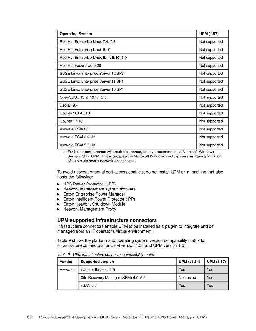
UPM supported infrastructure connectorsInfrastructure connectors enable UPM to be installed as a plug-in to integrate and be managed from an IT operator’s virtual environment.
Table 9 shows the platform and operating system version compatibility matrix for infrastructure connectors for UPM version 1.54 and UPM version 1.57.
Table 9 UPM infrastructure connector compatibility matrix
Red Hat Enterprise Linux 7.4, 7.3 Not supported
Red Hat Enterprise Linux 6.10 Not supported
Red Hat Enterprise Linux 5.11, 5.10, 5.9 Not supported
Red Hat Fedora Core 28 Not supported
SUSE Linux Enterprise Server 12 SP3 Not supported
SUSE Linux Enterprise Server 11 SP4 Not supported
SUSE Linux Enterprise Server 10 SP4 Not supported
OpenSUSE 13.2, 13.1, 12.3 Not supported
Debian 9.4 Not supported
Ubuntu 18.04 LTS Not supported
Ubuntu 17.10 Not supported
VMware ESXi 6.5 Not supported
VMware ESXi 6.0 U2 Not supported
VMware ESXi 5.5 U3 Not supported
a. For better performance with multiple servers, Lenovo recommends a Microsoft Windows Server OS for UPM. This is because the Microsoft Windows desktop versions have a limitation of 10 simultaneous network connections.
Vendor Supported version UPM (v1.54) UPM (1.57)
VMware vCenter 6.5, 6.0, 5.5 Yes Yes
Site Recovery Manager (SRM) 6.0, 5.5 Not tested Yes
vSAN 6.5 Yes Yes
Operating System UPM (1.57)
30 Power Management Using Lenovo UPS Power Protector (UPP) and UPS Power Manager (UPM)

UPM supported web browsersThe UPM graphical user interface can be accessed remotely using a simple web browser. Access to this interface can be secured through Secure Socket Layer (SSL) connection and is also secured through login and password.
The UPM graphical interface has been tested and is supported with the following web browsers:
� Google Chrome� Mozilla Firefox� Microsoft Internet Explorer version 9 and later
Installing UPM
For Windows and virtual deployments, download the applicable software, available from:
http://datacentersupport.lenovo.com/us/en/solutions/lnvo-ups-mgmt
Once downloaded, run the installation file for Windows or install the OVA for virtual environments. Figure 17 shows the welcome screen. Follow the standard prompts to install the software.
Note that when UPM requires the use of infrastructure connectors (used for example in VMware), Java Runtime Environment (JRE) must be installed for UPM to fully function. Download the latest JRE from:
http://www.java.com/en/download
Citrix XenCenter 7.3 Not tested Yes
XenServer 7.3 Not tested Yes
XenCenter 7.2, 7.1, 7.0, 6.5, 6.2 Yes Yes
XenServer 7.2, 7.1, 7.0, 6.5, 6.2 Yes Yes
Microsoft SCVMM 2012 R2, 2012, 2008 R2 Yes Not tested
Hyper-V role & server core 2016, 2012 R2, 2008 R2 Not tested Yes
Nutanix Prism v4 Yes Yes
Acropolis Yes Yes
Cisco UCS Manager 3.0, 2.2, 2.1 Yes Yes
NetApp Data ONTAP 8.2, 8.1.2, 8.1.1 Yes Not tested
Data ONTAP/Solid Fire 9.1, 8.3 Not tested Yes
Note: Infrastructure connectors all requires Java Runtime Environment (JRE) 8. JRE 9 and JRE 10 are not supported.
Note: While IE 9 or later is supported, for optimal performance either Google Chrome or Firefox browsers should be used.
Vendor Supported version UPM (v1.54) UPM (1.57)
31
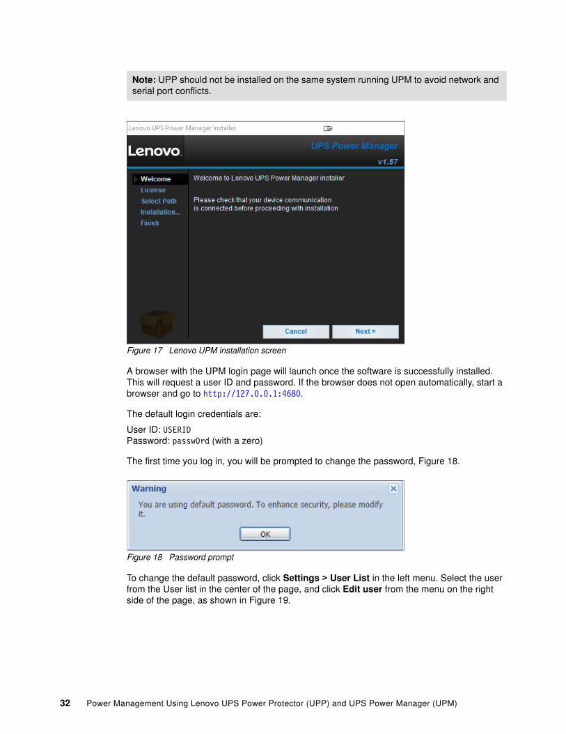
Figure 17 Lenovo UPM installation screen
A browser with the UPM login page will launch once the software is successfully installed. This will request a user ID and password. If the browser does not open automatically, start a browser and go to http://127.0.0.1:4680.
The default login credentials are:
User ID: USERID Password: passw0rd (with a zero)
The first time you log in, you will be prompted to change the password, Figure 18.
Figure 18 Password prompt
To change the default password, click Settings > User List in the left menu. Select the user from the User list in the center of the page, and click Edit user from the menu on the right side of the page, as shown in Figure 19.
Note: UPP should not be installed on the same system running UPM to avoid network and serial port conflicts.
32 Power Management Using Lenovo UPS Power Protector (UPP) and UPS Power Manager (UPM)

Figure 19 Change default password once logged in
Figure 20 shows the UPM web interface. This page will display devices (UPSs, PDUs and servers) once they are discovered on the network. Discovery is described in “Discovering devices in UPM and UPP” on page 34.
Figure 20 Lenovo UPM web interface - discovery page
Applying a Silver or Gold license
To enable all of the features and benefits of UPM a silver or gold license will need to be applied once the user has logged in. To enter a license, click on System on the right hand side menu, then right click in the main menu and select Edit system information as shown in Figure 21 on page 34.
33

Figure 21 License key
Discovering devices in UPM and UPP
When UPM is initially launched, an automatic discovery for devices will take place if it detects a network.
A discovery can also be forced by clicking Settings > Auto Discovery in the left-hand menu, as shown in Figure 22.
Figure 22 Auto discovery
There are three scanning methods available. You can select these from the menu on the right side of the window, as shown in Figure 26 on page 37.
34 Power Management Using Lenovo UPS Power Protector (UPP) and UPS Power Manager (UPM)

� Quick scan: This option scan at port 4679 and tftp port 69. In a few seconds it will discover all network connected equipment, as well as other manufacturers’ UPSs and PDUs on the subnet your computer is on. A quick scan automatically runs each time UPM is launched or turned on. You can manually initiate a scan by clicking on the Auto Discovery if you want to run it again or if you are adding equipment.
Note: The quick scan will only scan on the subnet it is installed on and can not look outside that subnet. To discover devices outside of the subnet it is installed on, use the range scan, discussed below.
� Range scan: This option is used the most. Click Add Range and enter the starting IP address and ending IP address of the range you want to scan. This method can be used to discover devices that are outside of the network segment. The dialog box is shown in Figure 23.
Figure 23 Range scan settings
Range scan also has an option Override global authentication settings which can be checked if the you need to provide XML authorization, change the SNMP community, or configure SNMP v3 or NUT protocols. Figure 24 on page 36 shows the fields presented when this option is checked.
35

Figure 24 Override global authentication settings
Once the IP addresses have been added, click Scan to begin the scan for new devices.
� Address(es) scan: This allows the user to put in one or more IP addresses to scan for specific UPSs or PDUs as shown in Figure 25.
The scan can be implemented immediately if the device exists on the network. If the device is not yet connected to the network, Force node(s) creation can be used. This means if there is one team installing devices physically in the data center, and another team is setting up UPM, the software team can force save the IP address of the devices being set up for future discovery. When the device is physically connected to the network, UPM automatically sees it and drops it into the discovered list.
The dialog also includes the option, Override global authentication settings which provides the same options as shown in Figure 24.
Figure 25 Address(es) scan options
Figure 26 on page 37 shows UPM with its discovered devices. If more than 10 devices are attempting to be discovered, UPM will prompt for a license code. Enter the appropriate Silver or Gold license code to continue discovering. See “Installation prerequisites” on page 29 for details about licensing.
36 Power Management Using Lenovo UPS Power Protector (UPP) and UPS Power Manager (UPM)

Figure 26 UPM discovered devices
Once UPM has discovered devices, you can begin monitoring, as we discuss in the next section.
Configuring UPM
This section has the following topics:
� “Introduction to monitoring with UPM and UPP” on page 37� “Configuration policies” on page 42� “Standard and custom events with UPM” on page 43� “Creating actions” on page 49� “Editing an action” on page 53
Introduction to monitoring with UPM and UPPThe UPM Node List from the left hand menu is the central view for all of the discovered devices. Devices shown include UPSs, PDUs, instances of UPP and storage devices. If virtualization is being used, it will also show the hosts and virtual machines. Note that functionality for virtualization instances requires either a Silver and Gold license.
The node list can display information on the discovered devices including:
� Type� Status � IP address� Mac address� Description� Serial number� Class� Version� OS type� Location� Contact� Load level
37

� Battery capacity� Shutdown timer� Estimated runtime to shutdown� Battery runtime� Showdown duration� Master output� Power source� Outlet group� Access� Link� Configuration policies list� Discovery date
Clicking on the Node List option in the left hand menu as seen in Figure 27, “Node List”, will display all of the discovered devices.
Figure 27 Node List
Figure 28 displays the UPM node list page with the discovered devices.
Figure 28 Discovered devices on UPM dashboard
The UPS information panel on a discovered power device can be shown in Figure 29.
38 Power Management Using Lenovo UPS Power Protector (UPP) and UPS Power Manager (UPM)

Figure 29 UPS information panel
Environmental information can also be displayed if a environmental monitoring probe (EMP) is connected to the device, as shown in Figure 30. The EMP panel will be displayed on the right hand side menu when Node List is selected.
Figure 30 EMP information panel
Organizing the node listIf UPM is monitoring a large number of devices and/or data centers, then sub-views and groups with specific categories of devices can be created to help organize and manage them.
There are a number of ways to organize how discovered devices are viewed, including:
� Sub-views� Grouping� Mapping
Each of these are discussed in more detail below.
Sub-views: Create sub-views (including sub-views with sub-views to specify as high as a region, down to a state, down to a building, floor, rack) to divide all the discovered UPS and group accordingly, as shown in Figure 31. This is useful if there are multiple power devices.
39
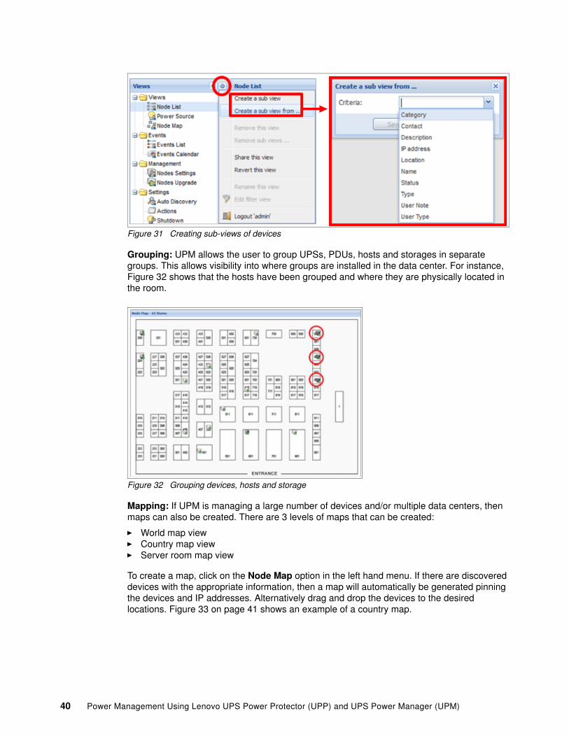
Figure 31 Creating sub-views of devices
Grouping: UPM allows the user to group UPSs, PDUs, hosts and storages in separate groups. This allows visibility into where groups are installed in the data center. For instance, Figure 32 shows that the hosts have been grouped and where they are physically located in the room.
Figure 32 Grouping devices, hosts and storage
Mapping: If UPM is managing a large number of devices and/or multiple data centers, then maps can also be created. There are 3 levels of maps that can be created:
� World map view� Country map view� Server room map view
To create a map, click on the Node Map option in the left hand menu. If there are discovered devices with the appropriate information, then a map will automatically be generated pinning the devices and IP addresses. Alternatively drag and drop the devices to the desired locations. Figure 33 on page 41 shows an example of a country map.
40 Power Management Using Lenovo UPS Power Protector (UPP) and UPS Power Manager (UPM)

Figure 33 Country level map
Viewing device informationFrom the UPM node list, select any device that has been discovered in the network and view the information panel on the right hand side of the screen as shown in Figure 34.
Figure 34 Information panel
This panel has real-time status information about the device that has been selected. This includes for instance on a UPS:
� Battery state (on/off/charging)� Power source (stand-alone/on utility)� Load level� Battery capacity
41

� Runtime based on the load
Other information that is reported here includes:
� Description of device� Firmware level� Nominal Active power (for example, if a 3kVA UPS is attached, the nominal active power
can be 3000W)� IP address� Serial number of the device� Location and contact person if set.
There are multiple tabs with information, including:
� Measurement tab: The measure pane is a graphical representation of the real-time power consumption (for instance, monitor the battery input and output voltage, battery runtime and load level) of a device. This feature allows the user to compare and measure up to 6 devices against each other ranging from 1 hour up to 7 days.
� Global Events tab: The events pane stores all of the events that happen on a device, it displays the status, date, message.
� System tab: View UPM ‘about’ information, configure regional settings
� Log tab: Stores internal messages in the system log.
The following section discusses the events and actions on the discovered devices with UPM.
Configuration policiesConfiguration policies are a way of packaging information. They can be configured to define a set of information and certain parameters on a node or group of nodes. These are required for example, to define additional information about a node, define a nodes power source and define the timing of when to trigger an action. This allows the user to group nodes by criticality, shutdown settings, power source, or what ever may be relevant.
To create a new policy, click the Configuration Policies from the left hand menu then click Create new policy from the right hand menu. The configuration policy options can be shown in Figure 35.
Figure 35 Configuration policy options
42 Power Management Using Lenovo UPS Power Protector (UPP) and UPS Power Manager (UPM)

There are 4 policies that can be configured which include:
� Asset information: Attach and push information on an asset including user notes, service contact and service notes, to a node or group of nodes.
� Runtime threshold settings: Define threshold settings to a node or group of nodes. These thresholds (for example) allow the user to keep critical nodes running as long as possible and shutdown non-critical nodes first:
– Timer: Define the maximum duration between power loss and triggering of the protection action such as shutdown, moving VMs, email alert, etc.
– Remaining time limit: Define the time limit based on remaining battery time to perform an action such as shutdown, moving VMs, email alert, etc.
– Remaining capacity limit: Define the remaining battery capacity (as a percentage) to perform an action such as shutdown, moving VMs, email alert, etc.
– Shutdown duration: Define the number of seconds required to gracefully shutdown the target (a host, a VM or set of servers). This includes shutting down of operating system and applications.
� Power source: Define the PDU and/or UPS and the appropriate load segment that is powering the node(s).
� User settings: Define numeric and text values that can be attached to any node for informational purposes.
Once the appropriate configuration policies have been defined on the node(s) where applicable, events and actions can be deployed. The next section discusses how to create events and actions.
Standard and custom events with UPM
Once devices have been discovered and are being monitored with UPM, actions can be configured when events occur.
� An event provides the order for the action to occur while providing information to the events origin (ID, type of event and parameters related to the event).
� An action is the configured action to take when an event occurs. For example, an action could be to send an email when an alarm is generated,
For use features such as management, shutdown, infrastructure connectors, SRM capability, third party connections, data center management, user drivers, and redundancy to be implemented, they first need to be enabled in the UPM interface, as follows:
1. Click on System on the left hand menu, then right click anywhere in the main screen and select Edit modules settings, as shown in Figure 36 on page 44.
License required: Some events and actions require a Silver or Gold license. Refer to Table 2 on page 9 for a list of features available with Basic, Silver and Gold licenses. To enable a license, refer to “Applying a Silver or Gold license” on page 33.
43

Figure 36 System - edit module settings
2. In the Edit modules settings dialog shown in Figure 36, click the features you wish to enable.
3. Click Save.
There are two types of events:
� Standard events: These events are available to the basic version of the software and both silver and gold licenses.
� Custom events: These events are only available to silver and gold licenses.
Standard eventsFrom the Settings > Actions / Events menu on the left hand side, events can be defined and managed. There are seven standard (default) events to apply an action on. These are listed below.
� Information Alarm: Can be used to trigger actions� Warning Alarm: Can be used to trigger actions� Critical Alarm: Can be used to trigger actions� Unknown State Alarm: Can be used to trigger actions� Power Failure: Happens immediately once you lose power
44 Power Management Using Lenovo UPS Power Protector (UPP) and UPS Power Manager (UPM)
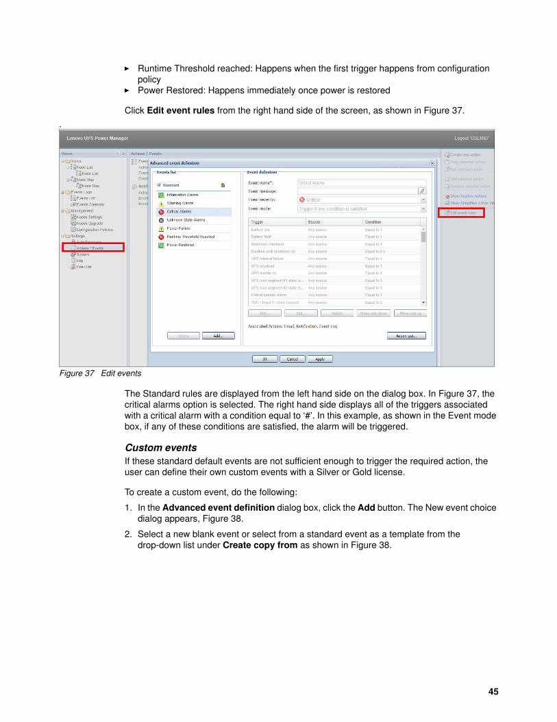
� Runtime Threshold reached: Happens when the first trigger happens from configuration policy
� Power Restored: Happens immediately once power is restored
Click Edit event rules from the right hand side of the screen, as shown in Figure 37.
.
Figure 37 Edit events
The Standard rules are displayed from the left hand side on the dialog box. In Figure 37, the critical alarms option is selected. The right hand side displays all of the triggers associated with a critical alarm with a condition equal to ‘#’. In this example, as shown in the Event mode box, if any of these conditions are satisfied, the alarm will be triggered.
Custom eventsIf these standard default events are not sufficient enough to trigger the required action, the user can define their own custom events with a Silver or Gold license.
To create a custom event, do the following:
1. In the Advanced event definition dialog box, click the Add button. The New event choice dialog appears, Figure 38.
2. Select a new blank event or select from a standard event as a template from the drop-down list under Create copy from as shown in Figure 38.
45
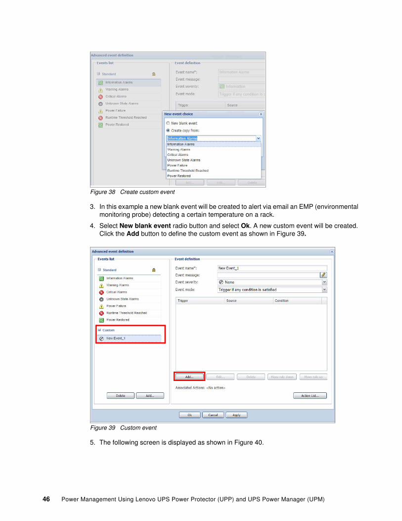
Figure 38 Create custom event
3. In this example a new blank event will be created to alert via email an EMP (environmental monitoring probe) detecting a certain temperature on a rack.
4. Select New blank event radio button and select Ok. A new custom event will be created. Click the Add button to define the custom event as shown in Figure 39.
Figure 39 Custom event
5. The following screen is displayed as shown in Figure 40.
46 Power Management Using Lenovo UPS Power Protector (UPP) and UPS Power Manager (UPM)

Figure 40 Add new event definition (rule trigger)
6. Click the Pencil icon next to the Rule trigger field to open the object selector, Figure 41.
7. To apply a trigger rule to a node, check the box Display only objects present in at the top of the window in Figure 41 and click the Pencil icon in the top-right corner. This will display the discovered nodes. Select a discovered node then click Ok. The object list will be updated with the custom triggers available to that node.
8. For the EMP temperature, select the Rule trigger on the environmental object Temperature. Click Add in Figure 40 again, enter the appropriate fields, then click Ok.
Figure 41 Select trigger rule and apply to node
47

9. Fill in the rest of the required fields, rule source, rule operator, value and grace period (s) as shown in Figure 42.
Figure 42 Rule definition
This example would mean if the temperature is greater than 28 °C degrees for more than 60 seconds it will be triggered. This is an advanced event with custom defined points that can be used to trigger an action.
10.Select OK. The trigger is added to the event definition page.
11.Fill in the Event definition fields in Figure 43, which include the following:
– Event name: The name of the event.
– Event message: The message to display when the event occurs (write a message and/or click the pen icon to insert an object such as location, contact, source ID, etc). This will appear when the event happens.
– Event severity: Define the severity of the event: “None”, “Information”, “Warning”, “Critical” and “Unknown”.
– Event mode: Define the condition for the event to occur: trigger if all conditions are met, or if any (one) condition is met.
Figure 43 Saved trigger
48 Power Management Using Lenovo UPS Power Protector (UPP) and UPS Power Manager (UPM)
12.If there are multiple trigger rules, then the order of the rules in the listed in the Event definition dialog box will define the order for the event to occur. Use the Add, Edit, Delete, Move rule down, Move rule up buttons to manage and define the order of the trigger rule list.
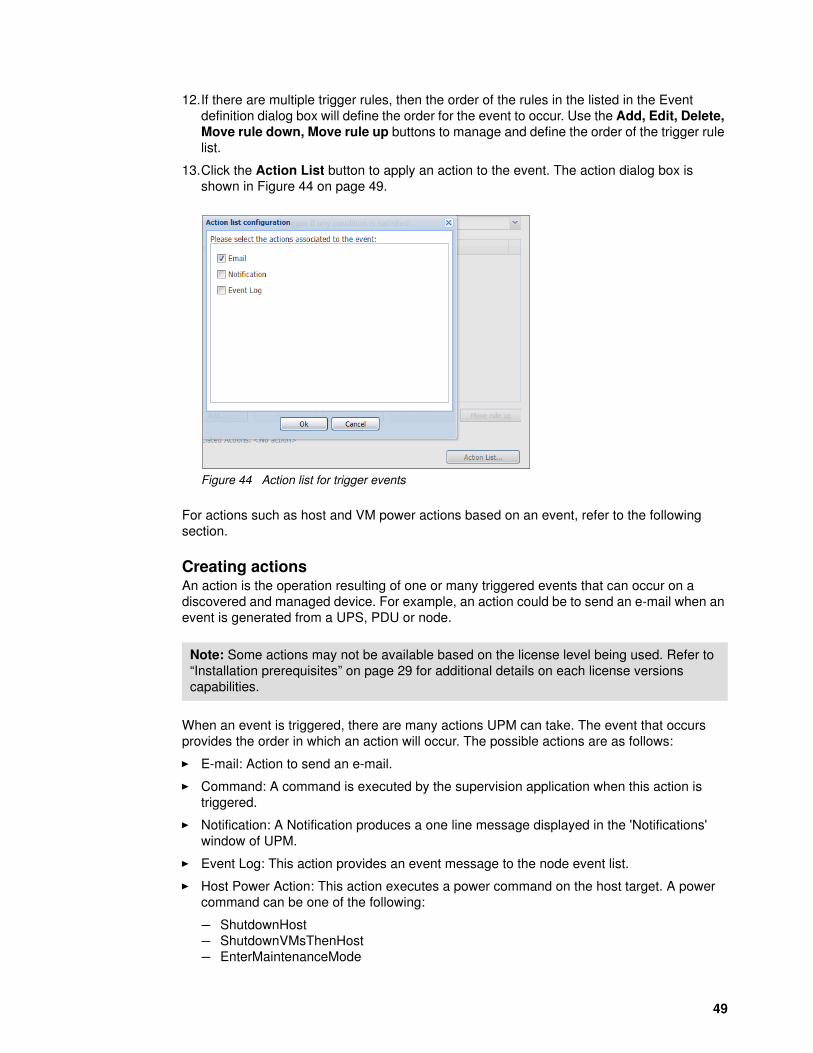
13.Click the Action List button to apply an action to the event. The action dialog box is shown in Figure 44 on page 49.
Figure 44 Action list for trigger events
For actions such as host and VM power actions based on an event, refer to the following section.
Creating actions An action is the operation resulting of one or many triggered events that can occur on a discovered and managed device. For example, an action could be to send an e-mail when an event is generated from a UPS, PDU or node.
When an event is triggered, there are many actions UPM can take. The event that occurs provides the order in which an action will occur. The possible actions are as follows:
� E-mail: Action to send an e-mail.
� Command: A command is executed by the supervision application when this action is triggered.
� Notification: A Notification produces a one line message displayed in the 'Notifications' window of UPM.
� Event Log: This action provides an event message to the node event list.
� Host Power Action: This action executes a power command on the host target. A power command can be one of the following:
– ShutdownHost– ShutdownVMsThenHost– EnterMaintenanceMode
Note: Some actions may not be available based on the license level being used. Refer to “Installation prerequisites” on page 29 for additional details on each license versions capabilities.
49
– EnterMaintenanceModeThenShutdown– ExitMaintenanceMode– EnterStandByMode– ExitStandByMode
� VM Power Action: This action executes a power command on a virtual machine. A power command can be one of the following:
– Power on– Power off– Guest shutdown– Suspend
� VM Migrate Action: This migrates a virtual machine from its host to another host.
� vApp Power Action: This action initiates the execution of a power command on a virtual application. The power command can be startup, shutdown, or suspended.
� Start a Recovery Plan: This starts a recovery plan in fail-over mode. For this action, the SRM (Site Recovery Manager) module must be active. The user can then choose a recovery plan for a recovery site.
� SSH Action: This action will execute a command on a server via a SSH connection.
� Command PDU Outlets: This action is used to start or stop one or several outlets of a PDU after a delay.
� Cluster Shutdown: Select this action to shutdown a cluster.
� Storage Action: To execute an action on a storage node.
� Volume Migration: Migrate a storage volume to another storage host.
� Power Capping: This action initiates a power capping action on a hardware server.
To create a new action, do the following:
1. Click the Settings > Actions / Events menu on the left hand side.
2. Click Create new action on the right side of the window, as shown in Figure 45.
Note: Only VMware nodes are available for VM Power, VM Migrate and vApp Power actions. These are not available for Hyper-V. To protect Hyper-V virtualization servers, select Management > Nodes Settings > Node configuration panel.
50 Power Management Using Lenovo UPS Power Protector (UPP) and UPS Power Manager (UPM)

.
Figure 45 Create new action
3. Fill in the required fields, giving the action a name and clicking the Pencil icon for the Event List option. As shown in Figure 46, the event list has all of the standard event options as well as any custom events that have been created.
Figure 46 Standard and custom events for actions
4. In the Select associated events dialog box, select an event to perform actions on (the standard event such as an alarm or threshold reached, or a customized event which has been already created). Click OK.
51

5. Use the Event Source field to specify any discovered source, a single discovered node or a cluster or group of nodes to assign the action on.
6. Select the Action type from Action Settings field, as shown in Figure 47.
Figure 47 Action type options for a new action
In this example, email has been selected as shown in Figure 48. This means that an email will be sent if a critical alarm happens. The email will contain dynamic information based on what is selected in the message field such as IP address, location.
Figure 48 Create new action - email on critical alarm
52 Power Management Using Lenovo UPS Power Protector (UPP) and UPS Power Manager (UPM)
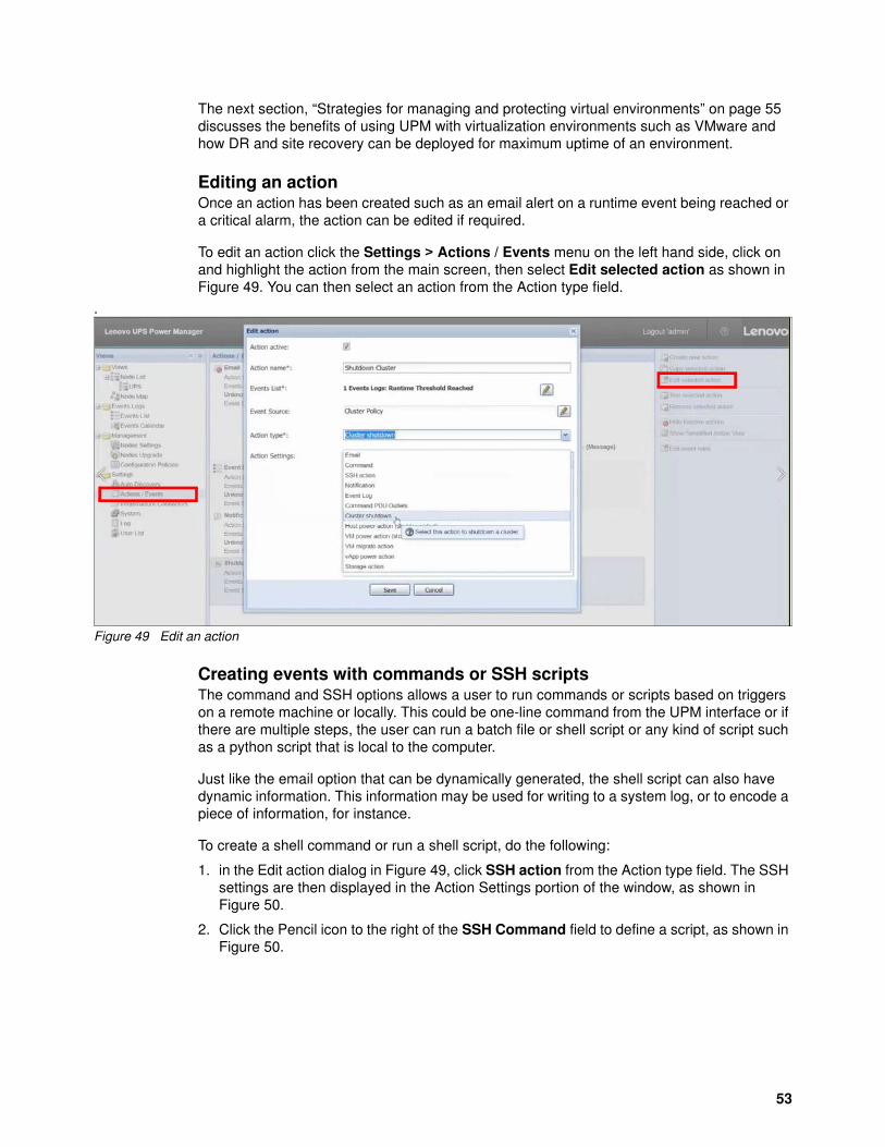
The next section, “Strategies for managing and protecting virtual environments” on page 55 discusses the benefits of using UPM with virtualization environments such as VMware and how DR and site recovery can be deployed for maximum uptime of an environment.
Editing an actionOnce an action has been created such as an email alert on a runtime event being reached or a critical alarm, the action can be edited if required.
To edit an action click the Settings > Actions / Events menu on the left hand side, click on and highlight the action from the main screen, then select Edit selected action as shown in Figure 49. You can then select an action from the Action type field.
.
Figure 49 Edit an action
Creating events with commands or SSH scriptsThe command and SSH options allows a user to run commands or scripts based on triggers on a remote machine or locally. This could be one-line command from the UPM interface or if there are multiple steps, the user can run a batch file or shell script or any kind of script such as a python script that is local to the computer.
Just like the email option that can be dynamically generated, the shell script can also have dynamic information. This information may be used for writing to a system log, or to encode a piece of information, for instance.
To create a shell command or run a shell script, do the following:
1. in the Edit action dialog in Figure 49, click SSH action from the Action type field. The SSH settings are then displayed in the Action Settings portion of the window, as shown in Figure 50.
2. Click the Pencil icon to the right of the SSH Command field to define a script, as shown in Figure 50.
53

Figure 50 Create new action - SSH command/script
3. You will be prompted as shown in Figure 51. Enter the command or script you wish to execute.
Figure 51 Create new action with dynamic information
4. To select dynamic information to include into a script, click the Pencil icon as highlighted in Figure 51. The objects that can be defined dynamically in the script are shown in the dialog box as shown in Figure 52.
54 Power Management Using Lenovo UPS Power Protector (UPP) and UPS Power Manager (UPM)

Figure 52 Dynamic information for a command/script
Information such a time, host name or IP address, source ID, location and contact can be contained in the actual command or local script that will run.
These SSH commands have endless possibilities and become extremely flexible particularly with the inclusion of dynamic information.
The next section discusses the functions and features of UPM with virtualization.
Strategies for managing and protecting virtual environments
Many data centers lack the ability to agilely react to disasters that can cause downtime of a data center. Downtime of a data center can cost tens of thousands of dollars for small businesses and in to the millions for large businesses.
Formulating and implementing a plan to maximize uptime of a data center in the event of a power disaster is a priority requirement to ensure business continuity. With widespread use of virtualization platforms providing many compelling advantages, virtualization does complicate power management in a number of ways.
Today, many data centers employ a separate set of management tools to monitor their power infrastructure, decreasing the productivity of their technicians and potentially delaying response times when problems occur. Additionally, while live migration capabilities can move VMs dynamically from one host server to another under a variety of conditions, few such products offer built-in functionality for migrating virtual workloads automatically during power outages, when the function is most often needed.
One of UPM’s most powerful features is its seamless integration with virtual management solutions. This section discusses the strategies for managing and protecting virtual
55

environments against failure, disaster recovery (DR) and site recovery using Lenovo UPS and Lenovo UPM and UPP software.
UPM and UPP strategy for management and protection
As discussed in “UPS Power Protection (UPP)” on page 16 and “UPS Power Manager (UPM)” on page 24 the capabilities of UPP and UPM allow an IT operator to build a custom designed disaster avoidance plan.
The disaster avoidance plan can use any of the available business continuity features offered by UPP and/or UPM, or a combination of the features to optimize the data center in case of a power outage or even if there is an environmental issue like a rack overheating.
Such business continuity features include:
� Automatically assemble a global, consolidated view of their backup power and power distribution infrastructure.
� Receive real-time notification of UPS and PDU trouble signs, such as deteriorating performance or an overheating battery.
� Shed non-critical loads to give increased battery runtime (or lessen generator load) for critical workloads or reduce temperatures in the data center.
� Power capping servers to give increased runtime to critical workloads or reduce temperatures.
� When required, shut down affected servers and network devices gracefully and automatically during extended utility failures, protecting unsaved work and preserving data integrity
� Fail-over critical loads to DR site using VMware SRM (planned migration) to avoid data loss (UPM)
The following section discusses virtualization with UPM.
Virtualization with UPM
UPM requires a Silver or Gold license for any virtualization infrastructure connectors to work. Refer to “Applying a Silver or Gold license” on page 33 for information on activating a license.
Also refer to “UPM supported infrastructure connectors” on page 30 for a list of support virtualization platforms with UPM.
Connecting an infrastructure connectorTo enable management of virtualization environments, infrastructure connectors need to be set up and connected for the specific OS environment being monitored and managed.
1. The Infrastructure Connectors option in the left hand menu of the main UPM screen will be hidden by default and needs to be enabled in the System page to access as shown in Figure 36 on page 44. Select the Infrastructure Connectors check box and click Save.
As shown in Figure 53, the Infrastructure Connectors option has appeared in the left hand menu of the UPM interface.
56 Power Management Using Lenovo UPS Power Protector (UPP) and UPS Power Manager (UPM)
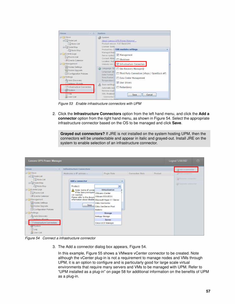
Figure 53 Enable infrastructure connectors with UPM
2. Click the Infrastructure Connectors option from the left hand menu, and click the Add a connector option from the right hand menu, as shown in Figure 54. Select the appropriate infrastructure connector based on the OS to be managed and click Save.
Figure 54 Connect a infrastructure connector
3. The Add a connector dialog box appears, Figure 54.
In this example, Figure 55 shows a VMware vCenter connector to be created. Note although the vCenter plug-in is not a requirement to manage nodes and VMs through UPM, it is an option to configure and is particularly good for large scale virtual environments that require many servers and VMs to be managed with UPM. Refer to “UPM installed as a plug-in” on page 58 for additional information on the benefits of UPM as a plug-in.
Grayed out connectors? If JRE is not installed on the system hosting UPM, then the connectors will be unselectable and appear in italic and grayed-out. Install JRE on the system to enable selection of an infrastructure connector.
57
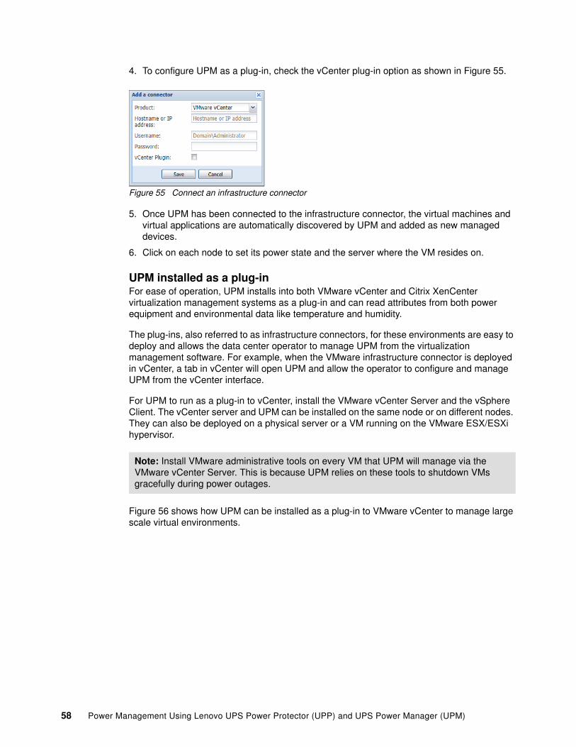
4. To configure UPM as a plug-in, check the vCenter plug-in option as shown in Figure 55.
Figure 55 Connect an infrastructure connector
5. Once UPM has been connected to the infrastructure connector, the virtual machines and virtual applications are automatically discovered by UPM and added as new managed devices.
6. Click on each node to set its power state and the server where the VM resides on.
UPM installed as a plug-inFor ease of operation, UPM installs into both VMware vCenter and Citrix XenCenter virtualization management systems as a plug-in and can read attributes from both power equipment and environmental data like temperature and humidity.
The plug-ins, also referred to as infrastructure connectors, for these environments are easy to deploy and allows the data center operator to manage UPM from the virtualization management software. For example, when the VMware infrastructure connector is deployed in vCenter, a tab in vCenter will open UPM and allow the operator to configure and manage UPM from the vCenter interface.
For UPM to run as a plug-in to vCenter, install the VMware vCenter Server and the vSphere Client. The vCenter server and UPM can be installed on the same node or on different nodes. They can also be deployed on a physical server or a VM running on the VMware ESX/ESXi hypervisor.
Figure 56 shows how UPM can be installed as a plug-in to VMware vCenter to manage large scale virtual environments.
Note: Install VMware administrative tools on every VM that UPM will manage via the VMware vCenter Server. This is because UPM relies on these tools to shutdown VMs gracefully during power outages.
58 Power Management Using Lenovo UPS Power Protector (UPP) and UPS Power Manager (UPM)

Figure 56 UPM installed as a vCenter plug-in
Alternatively, without VMware vCenter and no plug-in, management would appear as shown in Figure 57.
Figure 57 UPM managing without VMware vCenter
The UPM plug-in is shown in Figure 58 on page 59 with VMware vCenter.
Figure 58 UPM installed as a plug-in with VMware vCenter
Note, a plug-in can also be installed for Microsoft Hypervisor (Hyper-V) on the System Center Virtual Machine Manager (SCVMM). This works similar to what is shown in Figure 56, however requires UPP to be installed on each instance of the Hyper-V host nodes.
59

For a list of all infrastructure connectors supported by UPM, refer to, “UPM supported operating systems” on page 29.
UPM also integrates with VMware vRealize Operations Manager (vROps) and integrates with VMware Site Recovery Manager (SRM). The next section discusses UPM integration with SRM in more detail.
VMware Site Recovery Manager with UPM
UPM can be fully integrated with VMware Site Recovery Manager (SRM). When integrated with SRM, UPM becomes the power management suite which notifies the user in case of any UPS and power anomalies. SRM is then used to trigger the disaster recovery plan upon such anomalies.
When SRM is enabled and configured with UPM, the following benefits are realized:
� Starts recovery process on several different events: UPM will initiate the execution of recovery plans upon several different events.
� Less down time for end users: VMs will be down only for the amount of time required to transfer the latest snapshot to the DR site and will restart once the transfer is complete. The unprotected VMs will continue to run on the primary site.
� Customization for end users: Customize the script included in the package as needed. For example, customize SRM with UPM for low battery and protection loss features. UPM can trigger the customized SRM action when an event is triggered.
� Unattended execution of recovery plan before server crash: SRM with UPM provides recovery even before the entire site crashes. When the SRM feature is used, the backup will be ready even before the crash, which keeps the site continually secured.
Once the vCenter server and UPM have been configured, a power outage to one of the host servers will:
� Send an event that triggers an alarm in the vCenter Server alarms page
� Put the server into maintenance mode
� Use vMotion to migrate all VMs on the physical host server onto a different physical host server that has not lost utility power, if available
� If no server is available and SRM has been set up, migration will happen to the DR site.
� Shutdown the hypervisor gracefully
Note: UPM will automatically discover the IP address of the SRM server through the ExtensionManager and connects to it using the vCenter credentials.
60 Power Management Using Lenovo UPS Power Protector (UPP) and UPS Power Manager (UPM)

Figure 59 shows the architecture of SRM and UPM integration.
Figure 59 SRM and UPM protected and recovery site
The following prerequisites are required for SRM and UPM to function:
� SRM is configured at protected as well as recovery site.
� It is recommended that Latest version of UPM is installed at the recovery site.
� Windows PowerShell version 2.0 should be installed on the host on which UPM is installed.
� VMware vSphere PowerCLI installed on the machine.
� Administrators should have a basic knowledge of SRM and its configuration and UPM.
� The organization should have at least one recovery plan created in order to perform the disaster recovery.
Once UPM has been configured and is being protected with SRM at both the protected and the recovery site, it is recommended to create and test a recovery plan. This allows testing of the plan without interrupting production or backup nodes at either site.
Summary
It is virtually guaranteed that a utility company providing power to a data center will experience interruption to its service at some point in time. When this happens most data centers maintain contingency plans by relying on UPSs and switching over to back up generators until electrical service is restored. But in the event of extended outages, this sometimes may not be enough.
The Lenovo UPP and UPM software options re-define how data centers can securely and continually protect their data centers against power blips to extended outages, providing short term and long term action plans to protect both the hardware and integrity of the data.
61

Change history
January 2020:
� Update to Table 2, “UPP and UPM software licenses and features” on page 9: Support for SNMPv1 required at target device.
� Additional updates to Table 2, “UPP and UPM software licenses and features” on page 9:
– Configuartion policy– Shutdown Virtual Hosts (e.g. VMware ESXi)– Shutdown Storage– Advanced Event Action with Standard Events– Miscellaneous Advanced Actions, Generic SSH action– Safely shut down and restore high availability environments– Manage third-party power devices
November 2019:
� Update to Table 2, “UPP and UPM software licenses and features” on page 9: As of UPM v1.65.221, full Nutanix support requires a Silver license.
October 2019:
� Minor corrections
About the authors
Rani Doughty is a worldwide technical data center consultant with a background in x86 technology, storage, networking and software management platforms. She has worked in a technical space for over 16 years and currently supports worldwide on power, cooling, mechanical and space planning for greenfield and brownfield data center installations. Rani has authored over 15 books and papers and actively participates as a reviewer and author for ASHRAE publications. Rani holds an MBA and a double degree in Business and Masters of IT from the University of Ballarat, Australia.
Matt Archibald is the Director of Technical Architecture at nVent supporting the data center and networking space. Matt is deeply focused on liquid cooling (close-coupled and direct-to-chip), unified infrastructure management, data center monitoring, and automated data center infrastructure management. Previously, Matt was the Global Installation & Planning Architect for Lenovo Professional Services and spent over 15 years iin the data center space. Previous to this, Matt worked as a development engineer in the System x® and BladeCenter® power development lab doing power subsystem design for BladeCenter and System x servers. Matt holds 34 patents for various data center and hypervisor technologies. Matt has four degrees from Clarkson University in Computer Engineering, Electrical Engineering, Software Engineering, and Computer Science and a Bachelor of Engineering in Electronics Engineering from Auckland University of Technology.
Thanks to the following people for their contributions to this project:
� David Watts� Christian Flatscher
62 Power Management Using Lenovo UPS Power Protector (UPP) and UPS Power Manager (UPM)

Notices
Lenovo may not offer the products, services, or features discussed in this document in all countries. Consult your local Lenovo representative for information on the products and services currently available in your area. Any reference to a Lenovo product, program, or service is not intended to state or imply that only that Lenovo product, program, or service may be used. Any functionally equivalent product, program, or service that does not infringe any Lenovo intellectual property right may be used instead. However, it is the user's responsibility to evaluate and verify the operation of any other product, program, or service.
Lenovo may have patents or pending patent applications covering subject matter described in this document. The furnishing of this document does not give you any license to these patents. You can send license inquiries, in writing, to:
Lenovo (United States), Inc.1009 Think Place - Building OneMorrisville, NC 27560U.S.A.Attention: Lenovo Director of Licensing
LENOVO PROVIDES THIS PUBLICATION “AS IS” WITHOUT WARRANTY OF ANY KIND, EITHER EXPRESS OR IMPLIED, INCLUDING, BUT NOT LIMITED TO, THE IMPLIED WARRANTIES OF NON-INFRINGEMENT, MERCHANTABILITY OR FITNESS FOR A PARTICULAR PURPOSE. Some jurisdictions do not allow disclaimer of express or implied warranties in certain transactions, therefore, this statement may not apply to you.
This information could include technical inaccuracies or typographical errors. Changes are periodically made to the information herein; these changes will be incorporated in new editions of the publication. Lenovo may make improvements and/or changes in the product(s) and/or the program(s) described in this publication at any time without notice.
The products described in this document are not intended for use in implantation or other life support applications where malfunction may result in injury or death to persons. The information contained in this document does not affect or change Lenovo product specifications or warranties. Nothing in this document shall operate as an express or implied license or indemnity under the intellectual property rights of Lenovo or third parties. All information contained in this document was obtained in specific environments and is presented as an illustration. The result obtained in other operating environments may vary.
Lenovo may use or distribute any of the information you supply in any way it believes appropriate without incurring any obligation to you.
Any references in this publication to non-Lenovo Web sites are provided for convenience only and do not in any manner serve as an endorsement of those Web sites. The materials at those Web sites are not part of the materials for this Lenovo product, and use of those Web sites is at your own risk.
Any performance data contained herein was determined in a controlled environment. Therefore, the result obtained in other operating environments may vary significantly. Some measurements may have been made on development-level systems and there is no guarantee that these measurements will be the same on generally available systems. Furthermore, some measurements may have been estimated through extrapolation. Actual results may vary. Users of this document should verify the applicable data for their specific environment.
© Copyright Lenovo 2020. All rights reserved.Note to U.S. Government Users Restricted Rights -- Use, duplication or disclosure restricted by Global Services Administration (GSA) ADP Schedule Contract 63

This document was created or updated on January 30, 2020.
Send us your comments via the Rate & Provide Feedback form found athttp://lenovopress.com/lp1076
Trademarks
Lenovo, the Lenovo logo, and For Those Who Do are trademarks or registered trademarks of Lenovo in the United States, other countries, or both. These and other Lenovo trademarked terms are marked on their first occurrence in this information with the appropriate symbol (® or ™), indicating US registered or common law trademarks owned by Lenovo at the time this information was published. Such trademarks may also be registered or common law trademarks in other countries. A current list of Lenovo trademarks is available on the Web at http://www.lenovo.com/legal/copytrade.html.
The following terms are trademarks of Lenovo in the United States, other countries, or both:
BladeCenter®Lenovo®
Lenovo(logo)®System x®
The following terms are trademarks of other companies:
Linux is a trademark of Linus Torvalds in the United States, other countries, or both.
Hyper-V, Internet Explorer, Microsoft, PowerShell, Windows, Windows PowerShell, Windows Server, and the Windows logo are trademarks of Microsoft Corporation in the United States, other countries, or both.
Other company, product, or service names may be trademarks or service marks of others.
64 Power Management Using Lenovo UPS Power Protector (UPP) and UPS Power Manager (UPM)