power 'n motors - emcu solutions...power 'n motors critical aspects in power applications...
TRANSCRIPT

Power 'n Motors
Critical aspects in power applications
design, proper component selection
& experimental results

Agenda 2
9:00 Introduction
9:15 HV Motors (BLDC) & 3PHs Inverters
• Architectures & components
• New Intelligent Power Modules (IPM) from ST
1. Experimental results: Performance Benchmark
2. Guidelines to minimize EMI
11:00 Coffee break
11:15 IPM simulation tool
11:45 HV driving with isolation
• Driving an isolated 60kW HB driver: experimental results
12:15 LV Motors (DC & BLDC)
• Architectures & components
12:30 Lunch
13:30 LV Motors (DC & BLDC)
• Choosing right MOSFET for LV Motor Control (1h)
1. Relationship between MOSFET parameters & EMI behavior
2. Experimental results: Performances of new F7 Technology
14:30 ST solutions to drive three phases permanent magnet motors
• ST MCU Portfolio for Motor Control
• Software & Firmware
• Evalboard demonstration
16:00 Conclusions

ST solutions to drive three phases
permanent magnet motors
Software & Firmware
Evaluation boards
G. Forte
Systems Lab
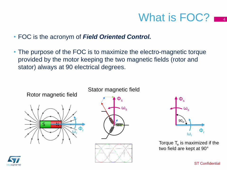
What is FOC?
• FOC is the acronym of Field Oriented Control.
• The purpose of the FOC is to maximize the electro-magnetic torque
provided by the motor keeping the two magnetic fields (rotor and
stator) always at 90 electrical degrees.
4
90el
Φs
ΦrΦr
Φs
ωs
ωr
ωs
ωr
Rotor magnetic fieldStator magnetic field
Torque Te is maximized if the
two field are kept at 90°

Benefits of FOC
• Best energy efficiency even during transient operation.
• Responsive speed control to load variations.
• Decoupled control of both electromagnetic torque and flux.
• Acoustical noise reduction due to sinusoidal waveforms.
• Active electrical brake and energy reversal.
5

PMSM FOC Basics• Field Oriented Control: stator currents (Field) are controlled in amplitude
and phase (Orientation) with respect to rotor flux
current sensing is mandatory (3shunt/1shunt/ICS)
speed / position sensing is mandatory (encoder/Hall/sensorless algorithm)
current controllers needed (PI/D,FF)
not easy… high frequency sinusoidal references + stiff amplitude modulation..
reference frame transformation (Clarke / Park) allows to simplify the problem:
6
Te maximized if…
Φr
Φs
90el90el
t

PMSM FOC Basics:reference frame transformations
7
• Clarke: transforms ia,ib,ic (120°) to iα,iβ (90°); (consider that ia+ib+ic=0);
• Park: currents iα,iβ , transformed on a reference frame rotating with their
frequency, become DC currents iq,id (90°)
• PI regulators now work efficiently in a ‘DC’ domain; their DC outputs, voltage
reference vq,vd are handled by the Reverse Park -> vα,vβ AC domain
3
2 bsas
as
iii
ii
ia ib ic
iα iβ
rrads
rrqs
iii
iii
cossin
sincos
iα iβ
iq
id
rdsrqs
rdsrqs
vvv
vvv
cossin
sincos
vq
vd
vα vβ

SMART
SHUTDOWN-BKIN,
DC V - TEMP
PMSM FOC – Block Diagram 8
Speed Control FOC Current Control
Motor
+
ωr*,t
vds
vqs+
-
-
PID
PID
iqd
iq*
id*
REVERSE PARK + circle
limitation
vabc
θr el
vαβ
iabc
PARK
θr el
iαβ
CLARKE
MTPA & FLUX WEAKENING CONTROLLER
Speed sensors:
Sensorless,
Hall,
Encoder
ROTOR SPEED/POSITION
FEEDBACK
PID
Te*
+
-
Space
Vector
PWM
Current
sensors:
3shunt/1shunt/
ICS
PHASE CURRENTS FEEDBACK
RAMP GENERATOR
ωr*
Gate drivers
Power Bridge
ST
SL
LIM
M™
IPM
ωr
DC domain AC domain
Motor

STM32 PMSM FOC SDK v4.1
STM32 PMSM FOC SDK v4.1• STSW-STM32100 - includes the PMSM FOC FW library and ST MC Workbench (GUI),
allowing the user to evaluate ST products in applications driving single or dual Field
Oriented Control of 3-phase Permanent Magnet motors (PMSM), featuring STM32F3xx,
STM32F4xx, STM32F0xx, STM32F1xx, STM32F2xx
9

STM32 FOC SDKKey Features
10
MC FW LIB v4.1
Plug-in: Digital PFC
1shuntFlux
WeakeningIPMSM MTPA
Feed ForwardSensor-less (STO + PLL)
Sensor-less (STO + Cordic)
Encoder Hall sensorsStartup
on-the-fly
ST MC Workbench
support
USART based com protocol
add-on
Max FOC F100 ~11kHzF0xx ~12kHz
3shunt
ICS(2)
FreeRTOS
F103, F2xx
Max FOC(3)
~23kHz
Dual FOC
Max FOC(3)
F103 ~23kHzF2xx ~40kHz
Max Dual FOC(3)
F103 ~20kHzF2xx ~36kHz
STM32F103x HD/XL, STM32F2xx
STM32F103x LD/MD
STM32F100x, STM32F0xx
STM32F4xx, STM32F3xx
(1) High Frequency Injection
Ne
w
Motor
Profiler
HFI(1)
Max FOC(3)
F3xx ~ 30kHzF4xx ~50kHz
Max Dual FOC(3)
F3xx~27kHzF4xx~45kHz
(3) Max FOC estimated in sensorless mode
(2) Supported only for STM32F103, STM3F2, STM3F4

ST PMSM FOC library 11
Features
• Speed/position sensors supported:
• Quadrature Encoder
Expensive sensor, usually only in robotics applications
• Hall Sensors
Cheaper sensors, usually for application requiring full torque at zero speed
• Sensor-less
High frequency injection (ST patent pending):
for anisotropic motors (IPMSM, Ld<Lq)
allows precise rotor angle detection; it enables advantages of FOC in torque/speed/position control mode at very low and zero speed
STM32F3 and STM32F4 only
State observer + PLL
Use electrical quantities (mainly current feedback) to estimate rotor position
Used for many applications not requiring full torque at zero speed or very low speed operations (< 3-5% of nominal speed)
State Observer + CORDIC
High Frequency Injection

ST PMSM FOC library 12
Features
• Current sensing topologies:
• 1 shunt resistor placed on the DC link
• ST patented algorithm
• Only one op-amp /shunt resistor is needed lowest cost
• Current reading algorithm may result in not accurate torque regulation
• 3 shunt resistors placed in the three legs
• Current reading accuracy: high
• Best compromise cost / performances
• 2 Isolated Current Sensors (ICS)
• Not dissipative current sensing topology mandatory when current exceed some tens Ampere
• Expensive
• Any possible configuration (2 motors x 3 current sensing x 3 speed sensors type) is supported by FW library

MC boards offer on ST.com 13
Kit: from isolated debug probe to motor

Motor control kits 14
STM32100B-MCKIT
STM3210B-MCKIT
Motor control kits
Part Number Description ST Link onboard Type
STM32100B-MCKIT Motor control starter kit for STM32F100 (128KB Flash) Value Line MCUs Yes Single drive
STM3210B-MCKITMotor control starter kit for STM32 (128KB flash) Performance and Access Line microcontrollers
No Single drive
Serial communication RS232
The motor control kit connections represented below can also be applied when combining STM32
control boards and evaluation power boards.

STEVAL-IHM042V1
STEVAL-IHM043V1 STEVAL-IFN003V1
ST complete inverters
Part Number Description ST Link onboard Type
STEVAL-IHM034V2Dual motor control and PFC demonstration board featuring the STM32F103 and STGIPS20C60
No Single/Dual drive
STEVAL-IHM036V1Low power motor control board featuring the SLLIMM™ STGIPN3H60 and MCU STM32F100C6T6B
No Single drive
STEVAL-IHM038V1 BLDC ceiling fan controller based on STM32 and SLLIMM-nano No Single drive
STEVAL-IHM040V1BLDC/PMSM driver demonstration board based on STM32 and the SLLIMM nano™
No Single drive
STEVAL-IHM042V1Compact, low-voltage dual motor control board based on the STM32F303 and L6230
Yes Single/Dual drive
STEVAL-IHM043V1 6-Step BLDC sensorless driver board based on the STM32F051 and L6234 No Single drive
STEVAL-IFN003V1 DC PMSM FOC motor drive No Single drive
15
STEVAL-IHM034V2 STEVAL-IHM036V1 STEVAL-IHM038V1 STEVAL-IHM040V1

STM32 evaluation boards
with MC connector
Part Number Description ST Link onboard(1) Type
STM3210E-EVAL Evaluation board for STM32 F1 series - with STM32F103 MCU No Single drive
STM3220G-EVAL Evaluation board for STM32 F2 series - with STM32F207IG MCU Yes Single drive
STM32303C-EVAL Evaluation board for STM32F303xx microcontrollers Yes Single/Dual drive
STM3240G-EVAL Evaluation board for STM32F407 line - with STM32F407IG MCU Yes Single drive
STEVAL-IHM022V1High density dual motor control demonstration board based on the
STM32F103ZE microcontrollerNo Single/Dual drive
STEVAL-IHM039V1Dual motor drive control stage based on the STM32F415ZG
microcontrollerNo Single/Dual drive
16
STM3210E-EVAL STEVAL-IHM022V1 STEVAL-IHM039V1STM32303C-EVALSTM3220G-EVAL STM3240G-EVAL
In-circuit debugger/programmer..
ST-LINK/V2
ST-LINK/V2-ISOL (2500 VRMS high isolation voltage)
(1) Only necessary for high-voltage applications or if not included with the evaluation board:

Part Number Description
STEVAL-IHM021V2 100 W, 3-phase inverter based on L6390 and UltraFASTmesh™ MOSFET for speed FOC of 3-phase PMSM motor drive
STEVAL-IHM023V3 1 kW 3-phase motor control evaluation board featuring L6390 drivers and new IGBT STGP10H60DF
STEVAL-IHM025V1 1 kW 3-phase motor control demonstration board featuring the IGBT SLLIMM™ STGIPL14K60
STEVAL-IHM028V2 2 kW 3-phase motor control demonstration board featuring the IGBT intelligent power module STGIPS20C60
STEVAL-IHM032V1150 W inverter featuring the L639x and STGD3HF60HD for 1-shunt based sinusoidal vector control and trapezoidal scalar control
STEVAL-IHM035V23-phase high voltage inverter power board for FOC and scalar motor control based on the STGIPN3H60 (SLLIMM™-nano)
STEVAL-IHM045V1 3-phase high voltage inverter power board for FOC based on the STGIPN3H60A (SLLIMM™-nano)
ST evaluation power boards
with MC connector17
STEVAL-IHM021V21KW
STEVAL-IHM023V31000WSTEVAL-IHM025V1
150W
STEVAL-IHM032V1
100WSTEVAL-IHM035V2
100WSTEVAL-IHM045V1
2000WSTEVAL-IHM028V2

ST PMSM FOC library 18
• Wide range of ST products supported (STM32, SLLIMM IPM, L639x,
IGBT/Power Mosfet) using PC tool configurator: ST MC Workbench
Features

New project creation (1/2)
Starting from the Hardware19
1. Applications
2. single or dual motor
3. board approach
4. motor
1
Choose:
2
3
4

New project creation (2/2)
Hardware for Motor Profiler20
Example
HW supporting Motor
Profiler

ST PMSM FOC library 21
• Real time tuning capabilities
Features

“Motor Profiler” why? 22
• Electrical and mechanical parameters are
required by the algorithms to define the model
of the motor
• It is required to tune the current regulators
• It is required for Sensorless state observer
algorithm
• It is required for additional features
• It is required to tune the speed regulators
Why motor electrical parameters are required by FOC?
Electrical
parameters
Electrical
parameters
Mechanical
parameters

“Motor Profiler” why? 23
• To measure the motor parameters can
requires specific skills and equipment
• Tuning of the regulators can be empirical
• Find the proper acceleration for the startup
can’t be easy
• Many trials and errors before to run the
motor
Sometimes to start the evaluation of motor control solution can be hard
+-
Startup
Fail

What can’t be measured 24
• Motor poles pairs
• Maximum Application speed
• Nominal speed of the motor will be computed and used to validate the maximum application speed insert by the user
• Nominal current
• Motor anisotropy Lq/Ld ratio
These parameters shall be insert by the user

Measure electrical parameters 25
• No additional HW and equipment required
• To perform the measurements is required to
apply a voltage and measure the current
• Usual PWM generation is used to supply the
voltage
• To compute the real voltage applied it is also
measured the DC bus voltage
• Usual motor phase current sensing is used
to measure the current
Electrical motor parameters measurement
Electrical motor parameters

Current regulators tuning 28
• Once the Rs and Ld are known, is possible
to tune-up the closed loop current regulators
• Kp and Ki of Iq and Id current regulator, and
related dividers, are computed according a
single common parameter 𝜔𝑐𝑒 (current
regulation closed loop bandwidth)
• 𝜔𝑐𝑒 defines the closed loop electrical
constant time 𝜏𝑐𝑒
Automatic tuning of current regulators
Current regulators tuning
𝐼𝑞,𝑑
𝐼𝑞,𝑑_𝑟𝑒𝑓
𝜏𝑐𝑒Time
0.63 𝐼𝑞,𝑑_𝑟𝑒𝑓

Measure electrical parameters 29
• To measure the Ke (motor BEMF voltage
constant) is necessary that the motor is running
• With tuned current controllers it is possible to
apply an open loop acceleration (Startup)
• On the fly measurement of Ke is performed
using the motor model
Startup and Ke measurement
Startup and Ke measurement

Mechanical motor parameters 30
• First order (inertial plus frictional) mechanical
system model is used to perform the
measurement
Mechanical motor parameters measurement
Mechanical motor parameters

Mechanical motor parameters 31
• The measurement of the moment of inertia is
done through the measurement of the
mechanical constant time 𝜏𝑚
Measurement of J (moment of inertia)
Measure of J

Speed regulators tuning 32
• Once the J and F are measured is possible
to tune-up the closed loop speed regulators
• Kp and Ki of speed regulator, and related
dividers, are computed according a single
common parameter 𝜔𝑐𝑚 (speed regulation
closed loop bandwidth)
• 𝜔𝑐𝑚 defines the closed loop mechanical
constant time 𝜏𝑐𝑚
Automatic tuning of speed regulators
Speed regulators tuning
𝜔
𝜔𝑟𝑒𝑓
𝜏𝑐𝑚
0.63 𝜔𝑟𝑒𝑓

Motor Profiler + One Touch Tuning 33
Plug and Spin your Motor in less than 60 seconds
Motor stopped
• Rs measurement
• Ls measurement
• Current regulators set-up
Open loop
• Ke measurement
• Sensorless state observer set-up
• Switch over
Closed loop
• Friction coefficient measurement
• Moment of inertia measurement
• Speed regulator set-up
10 sec
5 sec
45 sec

www.st.com
For further info about STM32 PMSM FOC SDK, please visit:
http://www.st.com/stm32
Part number: STSW-STM32100
Downloads:
STM32 PMSM FOC SDK:http://www.st.com/web/catalog/tools/FM147/CL1794/SC961/SS1743/PF257936
UM1052:
STM32F PMSM single/dual FOC SDK
UM1053:
Advanced developer guide for STM32F PMSM single/dual FOC library
UM1080:
Quick start guide for STM32F PMSM single/dual FOC SDK V4.0
34
Motor Control Solution Eval Boards
Motor Control FORUM