power peak infinity 2 no. 8294 - zomby's rc models page
TRANSCRIPT

Bedienungsanleitung Operating instructions
Notice d’utilisation .
POWER PEAK INFINITY 2
No. 8294

Operating instructions Order No. POWER PEAK INFINITY 2 8294
1. Introduction
Dear customer, congratulations on your choice of the POWER-PEAK INFINITY 2 automatic battery charging sta- tion from the robbe range. You now possess a high-perfor- mance micro-processor controlled charger with battery management facilities. This charging station is very easy to use and control. Nevertheless, operating an automatic charger such as the POWER-PEAK INFINITY 2 does call for some knowledge on the part of the user. These instructions are intended to help you become familiar with the unit quickly. To ensure that you are able to exploit the charger’s potential to the full, please read right through these operating instruc- tions very carefully before you use your new automatic char- ging station for the first time. We hope you enjoy using your POWER-PEAK INFINITY 2 , and we are confident that you will have good results with it over a long period.
Contents
1.
2.
3.
4.
5.
6.
7.
8.
9.
Introduction
Specification l
Connections and controls
The use of batteries
The charger in use
The menu structure of the INFINITY 2 Modes of operation Screen displays Status symbols Supplementary display messages
Charging transmitter and receiver batteries
Charging flight packs and drive batteries
Discharging / balancing batteries
10. Charging lead-acid batteries
11. Safety notes
12. Interference emission (IEC)
13. WINCHARGE VI .O
Page
12
12
12
13
14
14 14 15 16 17
18
18
19
20
20
20
21
The POWER PEAK INFINITY 2 is a battery charger with two outputs, designed for rapid-charging a flight pack or drive battery at the main charge output (Output 0.1 - 5A), and for simultaneously charging a transmitter or receiver battery at the second output (TX-RX 250 mA).
The main output is intended for recharging NC flight packs and vehicle drive batteries consisting of 1 to 30 cells. The cell capacity should be within the range 0.25 to 2.0 Ah, which covers most types used in modelling. This output can also be used to recharge lead-acid batteries of 2, 4, 6, 8, 10 and 12 volts.
The unit is designed to be powered by a 12 V lead-acid bat- tery but can also be used with a well stabilised 12 V or 13.8 V mains power supply provided that it is powerful enough. Do not power the charger from a car battery charger.
2. Specification
Operating voltage:
Current drain: max. 17 A (30 cells)
Rapid charge output No. of cells: Maximum charge current:
Maximum discharge current:
1 to 30 cells (1.2 to 36 V) up to 36 V: approx. 5 A above 36 V: 3 - 5 A up to 9 V: 5 A above 9 V: 0.9 to 5 A (max. dissipated power approx. 45 W) O/50/1 00/I 501200 mA, variable or automatic automatic, Delta Peak
Trickle charge current:
Charge termination:
TX - Rx output No. of cells: Charge current:
Protective functions: output)
Dimensions: approx. 160 x 140 x 50 mm Weight: 630 g (incl. cables)
12 V car battery or well sta- bilised 12 V or 13.8 V mains power supply
4 to 8 (4.8 - 9.6 V) approx. 250 mA
- reverse polarity (input and
- short-circuit (output) - excess temperature guard - low voltage shut-down at
approx. 9.5 V
3. Connections and controls
MODE button: For selecting the five different modes of operation CHARGING MODE: Charges at currents within the range 0.1 A to max. 5 A DISCHARGING MODE: Discharges at currents within the range 0.1 A to max. 5 A CHAR -> DISC MODE: Up to 99 charge / discharge cycles DISC -> CHAR MODE: Up to 99 discharge / charge cycles LEAD BATTERY: Charges lead-acid batteries (2, 4, 6, 8, 10, 12 V) at max. 2 A current
START (STOP) button: Starts and stops the charge / discharge process. Press once to select mode of operation, Press again to stop the process manually.
UP / DOWN buttons: Leafs through screen displays. Press the UP button to move forward through the screen displays; press the DOWN button to move back.
-/+ buttons: For adjusting and leafing through parameters. Press ‘+’ to increase va ue, press ‘-’ to decrease value
12

Operating instructions
POWER PEAK INFINITY 2 Order No.
8294
Main charge output: Rapid charge output for charging and discharging 1 to 30 NC battery cells, or 2 to 12 V lead-acid bat teries.
TX-RX output: Charge output for 4-cell to 8-cell receiver or transmitter batteries.
Screen: Displays set parameters; also displays charge values during charging and discharging.
Cooling fan: Cools the charger. Never cover the fan opening!
Power supply input:
Ferrite ring:
For connection to a 12 V car battery or a powerful 12 V mains power supply.
Reduces interference radiation (IEC)
4. Using NC batteries
In the modelling world Nickel-Cadmium (NC) batteries have become virtually the standard method of powering radio con- trol equipment and electric power systems. These energy sources are extremely easy to maintain and very reliable. Even so, there are a number of basic rules which must be observed when handling these batteries; keep to the rules, and they will reward you with a long useful life and maximum possible capacity.
A new pack, or one which has not been used for a long peri- od, must be ‘balanced’ before use, i.e. all cells brought slow- ly to the same state of charge. The same applies to a pack which has been deep-discharged, in which the polarity of one or more cells may be reversed. Packs in this condition also need to be balanced before re-use. A pack is balanced by charging for about 24 hours at the current which corresponds to 10% of its nominal capacity (charge rate 0.1 C).
We have to differentiate between normal (slow) and rapid charging of NC batteries. The standard charge rate (C) is now in general use to define charge currents and discharge currents related to battery size: it represents the relationship between the charge current and the battery capacity. For example, if you want to charge a battery with a capacity of 600 mAh using a charge rate of ‘1 C’, then you must set a charge current of 600 mA.
The term slow (or normal) charging covers the charge rates 0.1 -0.2c. An accelerated charge involves the use of a charge current of 0.3 - 0.5 C. The term rapid charging is generally applied to any process in which the charge current is higher than those already stated. If you wish to use a charge rate higher than 0.1 C, the charge process must be carefully monitored and switched off at the correct time, i.e. as soon as the pack is fully charged. This in turn calls for the use of a charger such as the POWER PEAK INFINITY 2 , which is capable of swit- ching off the charge current automatically when the pack is full.
13

Operating instructions Order No.
POWER PEAK INFINITY 2 8294
The best known method of charge termination is the Delta Peak principle. This requires the charger to monitor the vol- tage of the battery constantly, so that it can detect when the pack is fully charged and switch off the current at that point. Not all NC batteries are capable of being rapid-charged. This applies in particular to the packs used for transmitter and receiver batteries, which generally consist of cell types which are optimised for maximum capacity. The maximum charge current for this type of battery is limited to a fairly low level.
Before you set the charge current it is important to check that it does not exceed the limit for the type of battery in use.
Nickel-Cadmium batteries lose about 1% of their charge every day, which means that a fully charged pack will be completely flat after about 100 days in storage. This charac- teristic clearly implies that NC batteries must be charged up before each session.
If you know that you will not use a particular battery for a long period, it is better to discharge it and then store it in cool, dry conditions. It can then be restored to almost full capacity sim- ply by balancing the pack, i.e. giving it a single slow charge.
When using NC cells a number of safety measures must be observed, otherwise you run a real risk of causing personal injury and damage to property.
- NC cells must never be brought into contact with open fire, as they may explode.
- Never forcibly open NC cells as they contain corrosive chemicals.
- Never short-circuit the terminals of NC cells; fire and explosion hazard.
- A charged NC pack is not a toy. Keep such batteries well out of the reach of children.
NC batteries constitute toxic waste, and you should never dispose of them in the ordinary household rubbish. If you have a faulty or exhausted pack, discharge it completely, then hand it in to your local collection point in order to protect the environment. This can be your local toxic waste collection centre or any battery dealer. These dealers are obliged to accept batteries whether you purchased them there or not.
The batteries are then recycled, and the material is returned to the production process. Thus the toxic heavy metal does not reach the environment, and you have made your contri- bution to environmental protection.
5.The charger in use
When you wish to use the POWER PEAK INFINITY 2 it is very important to keep to the sequence of operations descri- bed below:
- ’ First connect the crocodile clips to a 12 V lead-acid bat- tery. Take great care to maintain correct polarity (red = positive, black = negative). The screen should now dis- play the message ‘robbe Modellsport / POWER-PEAK INFINITY 2. If not, either you have connected the croco- dile clips with reversed polarity, or the input voltage is too low.
- Connect the charge lead to the banana sockets on the charger, taking care to select correct polarity (red = posi- tive / black = negative). Now connect the NC battery with correct polarity. Caution: read the notes regarding IEC requirements.
Connecting the charger to the car battery, connecting a flight or drive battery to the charger
6.The menu structure of the INFINITY 2
Before you start charging or discharging a battery, you should make yourself familiar with the charging station’s menu structure. The first step is always to select the correct mode of operation for the process you wish to carry out.
Modes of operation
As mentioned in the earlier explanation of the charging sta- tion’s controls, the ‘MODE’ button is used to select the mode of operation before you start to use the charger. The following modes are available:
.- CHARGING MODE: Charges at a current within the
range 0.1 A to max. 5 A. This is the most important mode, and this is the one you will use to rapid-charge your flight packs and drive batteries.
DISCHARGING MODE: Discharges at a current within the range 0.1 A to max. 5 A; for checking the capacity of a bat- tery.
CHAR => DISC MODE: Charges a battery, then dischar ges it to balance the cells; up to 99 charge I discharge cycles.
DISC => CHAR MODE: Discharges a battery, then char ges it to balance the cells; up to 99 discharge I charge cycles.
LEAD BATTERY: Program for charging lead-acid batteries with nominal voltages of 2 to 12 V; max. charge current 2 A.
Each of the POWER PEAK INFINITY 2 ‘s operational modes has an associated screen display which appears for a short period after you press the ‘Mode’ button to select a new mode. Examples of these displays are shown in the detailed explanation of the individual operational modes. It is not pos- sible to alter the mode of operation while a charge or dischar- ge process is actually in progress.
14
Operating instructions
POWER,PEAK INFINITY 2
Screen displays
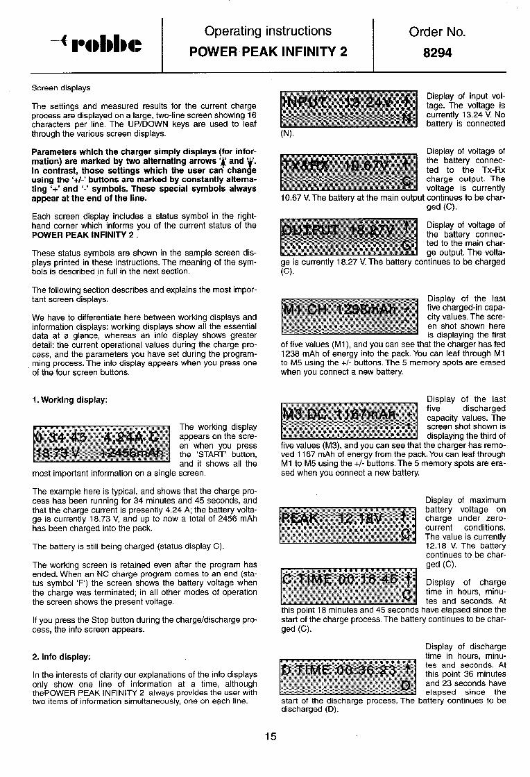
The settings and measured results for the current charge process are displayed on a large, two-line screen showing 16 characters per line. The UP/DOWN keys are used to leaf through the various screen displays.
Parameters which the charger simply displays (for infor- mation) are marked by two alternating arrows ‘4 and ‘ ‘. In contrast, those settings which the user can than t e using the ‘+/-’ buttons are marked by constantly alterna- ting ‘+’ and ‘-’ symbols. These special symbols always appear at the end of the line.
Each screen display includes a status symbol in the right- hand corner which informs you of the current status of the POWER PEAK INFINITY 2 .
These status symbols are shown in the sample screen dis- plays printed in these instructions. The meaning of the sym- bols is described in full in the next section.
The following section describes and explains the most impor- tant screen displays.
We have to differentiate here between working displays and information displays: working displays show all the essential data at a glance, whereas an info display shows greater detail: the current operational values during the charge pro- cess, and the parameters you have set during the program- ming process. The info display appears when you press one of the four screen buttons.
1. Working display:
The working display appears on the scre- en when you press the ‘START’ button, and it shows all the
most important information on a single screen.
The example here is typical, and shows that the charge pro- cess has been running for 34 minutes and 45 seconds, and that the charge current is presently 4.24 A; the battery volta- ge is currently 16.73 V, and up to now a total of 2456 mAh has been charged into the pack.
The battery is still being charged (status display C).
The working screen is retained even after the program has ended. When an NC charge program comes to an end (sta- tus symbol ‘F’) the screen shows the battery voltage when the charge was terminated; in all other modes of operation the screen shows the present voltage.
If you press the Stop button during the charge/discharge pro- cess, the info screen appears.
2. Info display:
In the interests of clarity our explanations of the info displays only show one line of information at a time, although thePOWER PEAK INFINITY 2 always provides the user with two items of information simultaneously, one on each line. .
Order No.
8294
Display of input vol- tage. The voltage is currently 13.24 V. No battery is connected
Display of voltage of the battery connec- ted to the TX-RX charge output. The voltage is currently
10.67 V. The battery at the main output continues to be char- ged (ch
Display of voltage of the battery connec- ted to the main char- ge output. The volta-
ge is currently 18.27 V. The battery continues-to be charged G) .
Display of the last five charged-in capa- city values. The scre- en shot shown here is displaying the first
of five values (Ml), and you can see that the charger has fed 1238 mAh of energy into the pack. You can leaf through Ml to M5 using the +/- buttons, The 5 memory spots are erased when you connect a new battery.
Display of the last five discharged capacity values. The screen shot shown is displaying the third of
five values (M3), and you can see that the charger has remo- ved 1167 mAh of energy from the pack. You can leaf through Ml to M5 using the +/- buttons. The 5 memory spots are era- sed when you connect a new battery.
Display of maximum battery voltage on charge under zero- current conditions. The value is currently 12.18 V. The battery continues to be char- ged w Display of charge time in hours, minu- tes and seconds. At
this point 18 minutes and 45 seconds have elapsed since the start of the charge process. The battery continues to be char- ged (0
Display of discharge time in hours, minu- tes and seconds. At this point 36 minutes and 23 seconds have elapsed since the
start of the discharge process. The battery continues to be discharged (D).
Operating instructions
POWER PEAK INFINITY 2
Order No.
8294
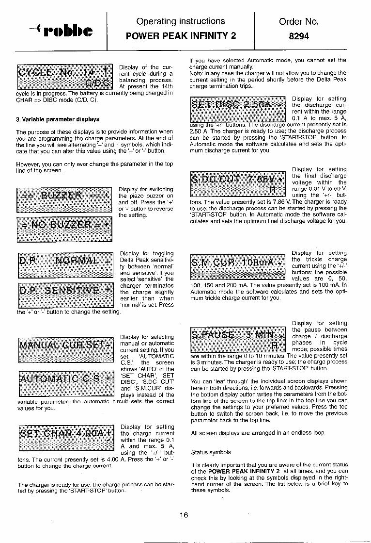
cm-in progress. The battery is currently being charged in CHAR => DISC mode (C/D, C).
3. Variable parameter displays
Display for setting the discharge cur- rent within the range 0.1 A to max. 5 A, drrent presently set is
The purpose of these displays is to provide information when 2.50-A. The charger is ready to use; the discharge process you are programming the charge parameters. At the end of can be started by pressing the ‘START-STOP’ button. In the line you will see alternating ‘+’ and ‘-’ symbols, which indi- Automatic mode the software calculates and sets the opti- cate that you can alter this value using the ‘+’ or ‘-’ button. mum discharge current for you.
However, you can only ever change the parameter in the top line of the screen.
Display for switching the piezo buzzer on and off. Press the ‘+’ or ‘-’ button to reverse the setting.
Display for toggling Delta Peak sensitivi- ty between ‘normal’ and ‘sensitive’. If you select ‘sensitive’, the charger terminates the charge slightly earlier than when ‘normal’ is set. Press
If you have selected Automatic mode, you cannot set the charge current manually. Note: in any case the charger will not allow you to change the current setting in the period shortly before the Delta Peak charge termination trips.
tons. The value presently set is 7.86 V. The charger is ready to use; the discharge process can be started by pressing the ‘START-STOP’ button. In Automatic mode the software cal- culates and sets the optimum final discharge voltage for you.
Display for setting the trickle charge current using the ‘+/-’ buttons; the possible values are 0, 50,
100, 150 and 200 mA. The value presently set is 100 mA. In Automatic mode the software calculates and sets the opti- mum trickle charge current for you.
the ‘+’ or ‘-’ button to change the setting.
Displav for settina
variable parameter; the automatic circuit - sets the correct values for you.
jsET
tons. The current presently set is 4.00 button to change the charge current.
Display for setting the charge current within the range 0.1 A and max. 5 A, using the ‘+/-’ but- A. Press the ‘+’ or ‘-’
The charger is ready for use; the charge process can be star- ted by pressing the ‘START-STOP’ button.
are within the range 0 to 10 minutes. The value presently set is 3 minutes. The charger is ready to use; the charge process can be started by pressing the ‘START-STOP’ button.
You can ‘leaf through’ the individual screen displays shown here in both directions, i.e. forwards and backwards. Pressing the bottom display button writes the parameters from the bot- tom line of the screen to the top line; in the top line you can change the settings to your preferred values. Press the top button to switch the screen back, i.e. to move the previous parameter back to the top line.
All screen displays are arranged in an endless loop.
Status symbols
It is clearly important that you are aware of the current status of the POWER PEAK INFINITY 2 at all times, and you can check this by looking at the symbols displayed in the right- hand corner of the screen. The list below is a brief key to these symbols.
16
Operating instructions
POWER PEAK INFINITY 2 Order No.
8294
N R
No battery connected. Charger ready, battery connected; you can start the selected mode by pressing the ‘START-STOP’ but ton.
C Battery being charged D Battery being discharged d/C,d Discharging in DISC=>CHAR mode d/c,c Charging in DISC=>CHAR mode c/cl,c Charging in CHAR=>DISC mode c/d,d Discharging. in CHAR=>DISC mode F Finished: selected process completed W Wait: pause in cycle mode
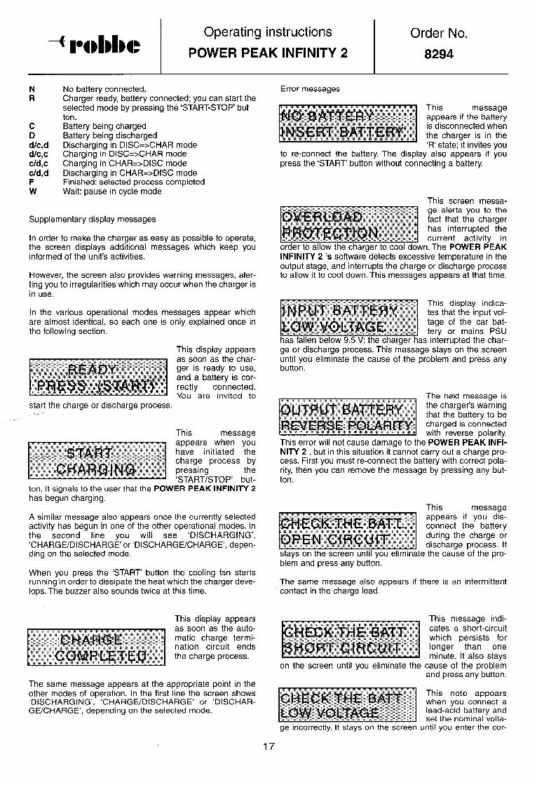
Supplementary display messages
In order to make the charger as easy as possible to operate, the screen displays additional messages which keep you informed of the unit’s activities.
However, the screen also provides warning messages, aler- ting you to irregularities which may occur when the charger is in use.
In the various operational modes messages appear which are almost identical, so each one is only explained once in the following section.
This display appears
start the charge or discharge process. ,---
This message
ton. It signals to the user that the POWER PEAK INFINITY 2 has begun charging.
A similar message also appears once the currently selected activity has begun in one of the other operational modes. In the second line you will see ‘DISCHARGING’, ‘CHARGE/DISCHARGE’ or ‘DISCHARGE/CHARGE’, depen- ding on the selected mode.
When you press the ‘START’ button the cooling fan starts running in order to dissipate the heat which the charger deve- lops. The buzzer also sounds twice at this time.
This display appears
Error messages
to reconnect the battery. The display also appears if you press the ‘START’ button without connecting a battery.
This screen messa-
~~~ g;ktigrigr~ order to allow the charger to cool down. The POWER PEAK INFINITY 2 ‘s software detects excessive temperature in the output stage, and interrupts the charge or discharge process to allow it to cool down. This messages appears at that time.
display indica- lat the input vol- of the car bat- or mains PSU
rupted the char- ge or discharge process. This message stays on the screen until you eliminate the cause of the problem and press any button.
This error will not cause damage to the POWER PEAK INFI- NITY 2 , but in this situation it cannot carry out a charge pro- cess. First you must re-connect the battery with correct pola- rity, then you can remove the message by pressing any but- ton.
This message appears if you dis- connect the battery during the charge or discharge process. It
stays on the screen until you eliminate the cause of the pro- blem and press any button.
The same message also appears if there is an intermittent contact in the charge lead.
The same message appears at the appropriate point in the other modes of operation. In the first line the screen shows ‘DISCHARGING’, ‘CHARGE/DISCHARGE’ or ‘DISCHAR- GE/CHARGE’, depending on the selected mode.
on the screen until you eliminate the
This message indi- cates a short-circuit which persists for longer than one minute. It also stays
cause of the problem and press any button.
This note appears when you connect a lead-acid battery and set the nominal volta-
ge incorrectly. It stays on the screen until you enter the cor-
17

Operating instructions
POWER PEAK INFINITY 2
rect voltage for the lead-acid battery, and press any button.
This is an indication that a problem has occurred during the parameter setting process.
In this case you must ‘reset’ the charger by disconnecting it from the power supply, and then re-connect it.
All the error messages stay on the screen until you press a button; they then remain on the screen for a further three seconds. This comprehensive set of screen displays keeps you constantly informed of the state of your POWER PEAK INFINITY 2 .
Order No.
8294 ’
While the battery is being charged, you will see the message ‘TX&RX’ on the scre- en, together with the
current voltage of the transmitter or receiver battery. The typi- cal display here shows a transmitter battery on charge; bat- tery voltage is currently 10.24 V.
If you wish to charge a transmitter battery installed in a trans- mitter which is fitted with a protective diode, you will need to by-pass the diode; alternatively you can remove the battery from the transmitter for charging. It is also important to check that the cable conductors and the connectors fitted to the transmitter and receiver batteries can cope with the charge currents you intend to use. It is possible to charge a trans- mitter or receiver battery and charge a flight pack or drive battery at the same time, i.e. both outputs can be used simul- taneously.
7. Charging transmitter and receiver batteries 8. Charging flight packs and drive batteries
The POWER PEAK INFINITY 2 ‘s TX-RX 250 mA output is designed to charge receiver and transmitter batteries consi- sting of 4 to 8 NC cells.
The charge current is fixed at approximately 250 mA. There is no automatic Delta Peak charge termination circuit on this output, so it is up to the user to calculate,the charge period required.
To calculate the charge time in hours use this formula:
charging time (h) = 1,4 x capacity of battery (mAh) / . . 250 (mA) ,
Once YOU have connected the char- ger to the car battery or mains PSU with correct polarity, you will see the two Start displays alternating
briefly on the screen.
Press any button, and the Start display will disappear; you can then move on to the Setting display.
If the Start screen does not appear, then either you have connected the voltage source with reverse polarity, or the power supply voltage .is too low. You must eliminate this fault immediately.
Ensure that the POWER PEAK INFINITY 2 is always connected to a fully charged car battery with plenty of reser- ve capacity, or to a well stabilised 12 V or 13.8 V mains PSU of adequate power.
We recommend a POWER MAINS UNIT from our range, e.g. Order No. 8334 or 8335.
With the charger correctly connected to its power source, connect a suitable charge lead to the charger’s TX-RX output, and then to the transmitter or receiver charge socket.
If you wish to recharge a flight pack or drive battery using thePOWER PEAK INFINITY 2 , the initial procedure is exac- tly as described in the previous section: first you connect the charger to the power supply, then connect the pack to be charged, then select the mode of operation using the ‘MODE’
button. To rapid-char- ge a flight -pack or drive battery you should select the ‘CHARGING MODE’.
At this stage you can set the variable parameters, e.g. the charge current (see variable parameter displays), or si.rnpry select automatic mode. Please refer to the battery manufac- turer’s stated range of permissible charge currents. The actual charge process is started by pressing the ‘START STOP’ button. After a minute the charger switches off the cur- rent for a period of about 5 seconds, so that it can measure the pack’s voltage under zero-current conditions.
The end of the charge process is indicated by an appropria- te message on the screen (‘F’), and - if the buzzer is switched on - by an audible signal. You can also interrupt the charge process manually at any time by pressing the ‘START-STOP’
button.
Please don’t disconnect the battery while the charge process is in progress. If you wish to interrupt the process, first press the ‘START-STOP’ button, otherwise the error message already mentioned (‘OPEN CIRCUIT’) will appear.
All ‘battery data’, e.g. the charged-in capacity and the maxi- mum battery voltage (PEAK), is stored by the charger after you disconnect the battery, and is retained until either you disconnect the charger from its power supply, or you connect a new pack to it. The variable parameters you have set are retained even after the power supply is interrupted, i.e. next time you use the charger the last used parameters will be available again.
The charge process begins when you connect the battery.

Operating instructions Order No. POWER PEAK INFINITY 2 8294
Please note that the potential maximum charge current of 5 A varies according to the number of cells in the pack (see Specification).
A pack which is already fully charged will have a high internal resistance, and in automatic mode it will only be charged at a very low rate.
If you encounter problems when attempting to use automatic current setting with some older types of battery, we recom- mend that you charge them with a manually set current.
9. Discharging / Balancing batteries
The procedure for setting up the POWER PEAK INFINITY 2 ready for use has already been described in the preceding sections. If you wish to discharge a battery, first connect the
The measured values, e.g. the discharged capacity, are sto- red by the charger after you disconnect the battery, and are retained until either you disconnect the charger from its power supply, or you connect a new pack to it.
As in the case of a charge process, the variable parameters you have set for a discharge process are retained even after the power supply voltage is disconnected.
Please note also that the maximum discharge current varies according to the number of cells in the pack. The POWER PEAK INFINITY 2 ‘s software ensures that the maximum discharge power (see Specification) is not exceeded.
The POWER PEAK INFINITY 2 provides facilities for main- taining NC packs, i.e. for balancing new batteries, and also for reviving the performance of old packs.
This is the purpose of the two operational modes ‘CHAR- GE=>DISCHARGE’ and ‘DISCHARGE=> CHARGE’.
In ‘CHAR=>DISC’ mode the battery is first charged and then discharged, in order to balance the state of charge of the
ge, or simply select the automatic mode. Please observe the permissible currents stated by the battery manufacturer.
The discharge current can be selected within the range 0.1 A to 5 A. It is important to check that the cable conductors and the connectors fitted to the transmitter and receiver batteries can cope with the discharge currents you intend to use. A useful guide value for final discharge voltage is 0.85 V/NC cell.
Press the ‘START-STOP’ button to start the discharge pro- cess.
The end of the discharge process is indicated by an appro- priate message on
You can also manually interrupt the discharge process at any time by pressing the ‘START-STOP’ button.
When the discharge process is completed the screen displays the capacity removed from the pack.
This value can be used as an accurate basis for drawing con- clusions about the general condition of a pack, and allows you to check the state of your batteries at regular intervals.
As with charging, you should not disconnect the battery when it is being discharged without first pressing the ‘START-STOP’ button, otherwise you will see the corresponding error message.
WV..V. l - - V-. . WV. . . .V
POWER PEAK INFI- NITY 2 to carry out UP to 99 charge/discharge cycles using the ‘+/-’
buttons, provided that the display shown here is on the scre- en. In our example the charger is set to give IO cycles.
If a fully charged bat-
mode, so that the charger starts by
discharging the pack.
range 0 to IO minutes. In our example set to 2 minutes.
In both modes the length of the pause between the charge and discharge pro- cesses can be set to any value within the the interval has been
During that period the screen shows ‘PAUSE TIME’, and the set time counts down towards zero. At the same time the number of the cycle which is currently running is shown in the Info display as ‘CYCLE NO.‘.
Our example shows a
progress. . The discharge has alrea- dy lasted 45 minutes and 26 seconds, and
the battery continues to be discharged.
The most important parameters are shown in the working display for these processes too, with the purpose of providing you with all the essential information at a glance.
19

Operating instructions Order No.
POWER PEAK INFINITY 2 8294
I~~.~:, for a discharge pro-
hour. The battery is being discharged at a current of 2.14 A, and up to now more than 2 Ah has already been removed from the pack. The battery voltage is currently 8.73 V.
To differentiate between charged-in capacity (+) and dischar- ged capacity (-) the screen shows the prefix ‘+’ or ‘-’ before a capacity statement. The last letter in the top line (‘C’ or ‘D’) indicates whether the charge is presently carrying out a char- ge (C) or a discharge (D) process.
These two operational modes provide you with the means to check and maintain your batteries simply and efficiently. The unit stores and displays the last five charged-in or discharged capacity values, allowing you to draw direct conclusions about the general condition of the pack in question.
ThePOWER PEAK INFINITY 2 features a voltage converter which works in both directions (up and down), and it is this which makes it possible to charge and check 1 - 30 cells. This facility makes thePOWER PEAK INFINITY 2 the ideal unit for measuring and selecting individual battery cells.
10. Charging lead-acid batteries
ThePOWER PEAK INFINITY 2 charger can also be used to recharge all the types of lead-acid batteries commonly used in modelling. The first step is to select the ‘LEAD BATTERY’ mode of operation. The charge current is fixed, and the maxi- mum rate is 2 A. This mode can be used to charge lead-acid batteries with voltages ranging from 2 V to 12 V.
The nominal voltage of the lead-acid battery to be charged must first be set using the ‘+/-’ buttons, and this parameter
can be selected as long as the display shown above is on the screen. No furt- her adjustments are
possible or necessary. The ‘LEAD BATTERY’.mode is indi- cated by a ‘P’ before the status symbol.
The charge process is completely automatic, and the voltage of the lead-acid battery is constantly monitored. Lead-acid batteries are fully charged at a voltage of about 2.3 V per cell, and at this point the charger switches off the current.
The working display also shows the essential information when a lead-acid battery is on charge. This screen shot shows that a lead-acid battery has been on charge at 2 A for more than 28 minutes.
;l;o;; ,-’ “jib r i---s
been charged into the battery, and the battery voltage is
currently 12.93 V. The battery continues to be charged.
This option allows you to use thePOWER PEAK INFINITY 2 to recharge a 12 V starter battery from your car battery at the
20
flying site, and there are many other uses for this facility.
It is also possible to discharge lead-acid batteries in Discharge mode.
11. Safety notes
- The charger can become quite hot when running.
- Disconnect the charger from the power source if it is not to be used for a long period. Disconnect any batteries from it at the same time.
- Set up the unit on a hard surface (not carpet or felt) befo- re using it, so that its cooling slots are unobstructed for good air circulation.
- Do not place the charger or batteries on a flammable sur- face when in use, and never leave the charger running unsupervised.
- Protect the unit from damp.
- Take care to ensure correct polarity of the outputs.
- Avoid short-circuits.
- Do not connect a battery to the RS 232 serial port.
- Do not subject the charger to direct sunshine.
- Do not attempt to recharge any battery which is already hot. Allow packs to cool down to ambient temperature first.
- NC batteries must consist of cells of the same capacity, make and type.
- Do not charge two batteries in parallel.
- Keep to the battery manufacturer’s recommendations.
- Suitable only for use with rechargeable batteries.
12. Interference emission (IEC)
To keep within the IEC regulations, and to ensure that the POWER PEAK INFINITY 2 functions safely and reliably, the charge lead must be modified before using the charger.
Run the charge lead twice through the ferrite ring as shown in the picture below.

13. WINCHARGE VI .O
Operating instructions
POWER PEAK INFINITY 2 Order No.
&294
An RS 232 cable can be connected to the serial port on the left-hand side of the charger in order to transfer data to a PC. The transfer lead and ‘WINCHARGE VI .O’ software are avai- lable under Order No. 8066.
With this program you can create, save, analyse and print out charge and discharge graphs. The following values can be displayed in graphic form:
.
- charge voltage
- charge current
- charged-in capacity
- discharged capacity
- input voltage
- voltage at TX-RX output
- time axis
Our exam- ple shows the para- meters. You can conti- nue to use the PC while data is being measured and trans-
The system J require-
ments are quite modest: the program runs well on a 40 MHz 386 PC, and the operating system can be Windows (R) 3.11 or Windows (R) 95198.
robbe Modellsport GmbH & Co. KG
We reserve the right to alter technical specifications.
For your notes . . . . . . . . . . . . . . . . . . . . . . . . . . . . . . . . . . . . . . . . . . . . . . . . . . . . . . . . . . . . . . . . . . . . . . . .
. . . . . . . . . . . . . . . . . . . . . . . . . . . . . . . . . . . . . . . ‘ . . . . . . . . . . . . . . . . . . . . . . . . . . . . . . . .
. . . . . . . . . . . . . . . . . . . . . . . . . . . . . . . . . . . . . . . . . . . . . . . . . . . . . . . . . . . . . . . . . . . . . . . .
. . . . . . ..*............................................................... . . . . . . . . . . . . . . . ..*...........*..........................................
. . . . . . . . . . . . . . . . . . . . . . . . . . . . . . . . . . . . . . . . . . . . . . . . . . . . . . . . . . . . . . . . . . . . . . . .
. . . . . . . . . ..~.~~...................~~.....~~...............~~.........~.. . . . . . . . . . . . . . . . . . . . . . . . . . . . . . . . . . . . . . . . . . . . . . . . . . . . . . . . . . . . . . . . . . . . . . . . .
. . . . . . . . . . . . . . . . . . . . . ..*.........................................*...... . . . . . . . . . . . . . . . . . . . . . . . . . . . . . . . . . . . . . . . . . . . . . . . . . . . . . . . . . . . . . . . . . . . . . . . .
. ‘ . . . . . . . . . . . . . . . . . . . . . . , . , . . . . . . . . . . . . . . . . . . . . . . . . , . . . . . . . . . . . . . , . . . . . .
. . . . . . . . . . . . . . . . . . . . . . . . . . . . . . . . . . . . . . . . . . . . . . . . . . . . . . . . . . . . . . . . . . . . . . . . . . . . . . . . . . . . . . . . . . . . . . . . . . . . . . . . . . . . . . . . . . . . . . . . . . . . . . . . . . . . . . . . . . . . . . . .
. . . . . . . . . . . ‘ . . . . . . . . . . . . . . . . . . . . . . . . . . . . . . . . . . . . . . . . . . . . . . . . . . . . . . . . . . . .
. . ..*..............................................................,....