power plant familiarisation.ppt
DESCRIPTION
POWER PLANT FAMILIARISATIONTRANSCRIPT

POWER PLANT FAMILIARIZATIONBY
Er. Randhir KumarEr. Randhir Kumar

1 Intake
2 Penstock
3 Transformer
4. Power House
5. Generator
6. Runner
7. Draft tube
8. Tail Race
Principle of operation of a Hydro Station
The kinetic energy of falling water is first converted into mechanical energy in Turbine & then the mechanical energy is converted into electrical energy in Generator.


View of a Hydro Unit
Components
Generator
Turbine
Auxiliaries

Generator
CoolerRotor
Stator
Thrust Bearings
Air Gap


Stator Core
Made up of Silicon Steel laminated sheet with high permeability and low hystersis & eddy current losses

Stator Winding windings are copper conductors which carries the generated voltage.

Rotor It carries magnetic pole
& is revolved by turbine, resulting in power generation in stator.

Rotor

Pole
• Pole are mounted on rotor and It fulfills the need of a rotating magnetic field
Damper Bars
Dovetail keys
Core

Slip Rings
•Slip rings are installed on rotor to transfer the field current from the external excitation equipment to the field winding.
•The current flows through the stationary carbon brushes to the rotating slip rings, through insulated bars mounted in the hollow shaft and to the pole coil connections.

Guide Pads
To restrict the radial movement of machine.
GENERATOR

Segmented type guide bearing assembly
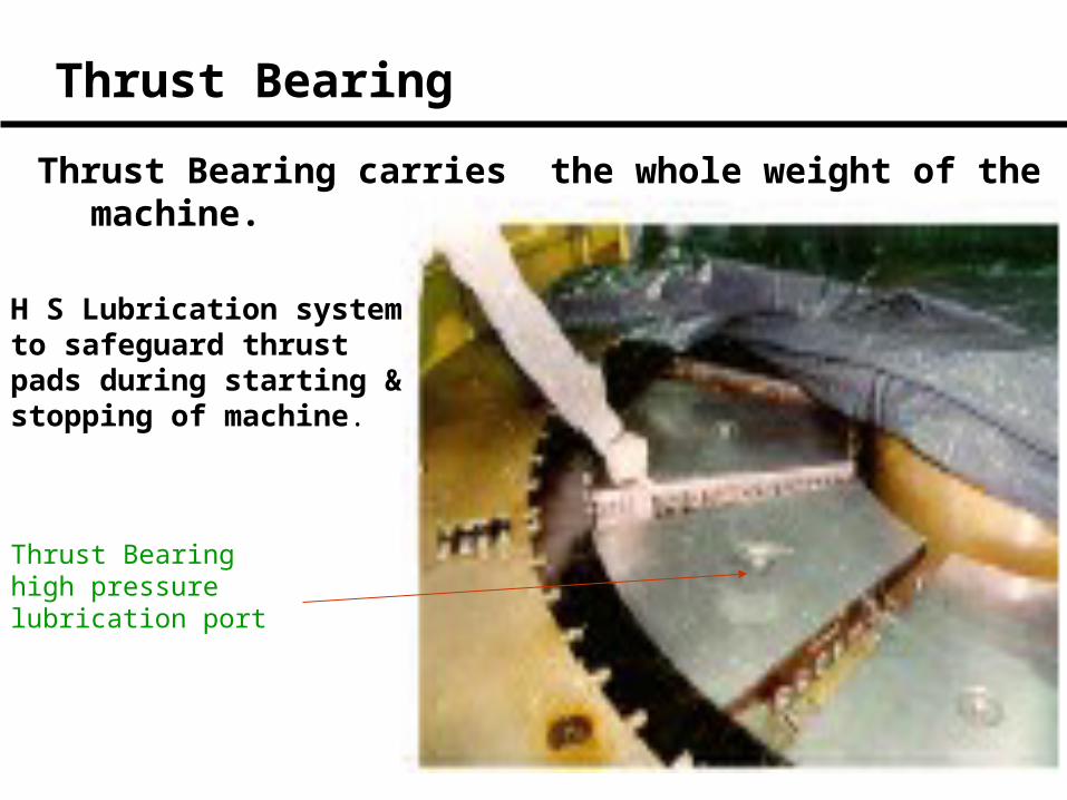
Thrust Bearing carries the whole weight of the machine.
Thrust Bearing high pressure lubrication port
Thrust Bearing
H S Lubrication system to safeguard thrust pads during starting & stopping of machine.

Bearing Pad Arrangement
Thrust Pad
H SLub Oil
Guide Pad
COoler
Cold Water
Hot Water
Oil
GENERATOR
TURBINE

Classification
Types of Turbine Types of Turbine
Kaplan Kaplan FrancisFrancis PeltonPelton
Medium & lower head up to 80 m when discharge& load vary widely
Medium & lower head up to 80 m when discharge& load vary widely
Medium & high Heads in the rangeof 30-550m, turbinedischarge varyingin acceptable limit
Medium & high Heads in the rangeof 30-550m, turbinedischarge varyingin acceptable limit
Heads greater than400m varying head,discharge and load conditions
Heads greater than400m varying head,discharge and load conditions
CLICK

Kaplan Runner
In a Kaplan runner blade angle varies with changing position of guide vanes. The runner blade servomotor is installed between themain turbine shaft and the generator shaft or inside the runner hub .
Oil Pipe line inside shaft
Hub
Cone
Runner Servomotor

PELTON FRANCIS

Spiral Casing
Guide Vane
Servomotor
Runner
Shaft Seal

Spiral Casing
Water from penstock enters the spiral casing which makes equal water thrust at each guide vane
Stay Vane

Spiral Casing
Stay Ring
Stay Vane
Guide Vane

Turbine

The wicket gate operating mechanism is installed with eccentric pins between the gate operating ring and each wicket gate to allow individual adjustment of wicket gate openings. Shear pins with carefully calculated size are provided with an operating mechanism. A pin will shear, should a wicket gate become blocked, and the remaining gates can be operated as required.
WICKET GATES AND OPERATING MECHANISM
REGULATING RING

Penstock Gate / MIV
Penstock Gate
MIV

• Brake
• H S Lub
• OPU system
• Cooling water
• Drainage , Dewatering
Some other auxiliaries

Practical braking speed 25-30% of rated speed
Brake
Air for BrakeOil for Jack
Rotating Machine

Oil Pressure Unit Supply pressurized oil to servomotor for opening or closing of guide vanes under the command of governor.
To system
oilairAir inlet

Cooling Water
For cooling of Generator Stator Windings
• Bearings
• Shaft Seals
• Transformer
• Fire Fighting

Open Loop Cooling water System
Booster Pump
Shaft Seal
Cooler(For Turbine
Bearings)
Oil Coolers(for Gen Bearings)
Air Coolers(For stator)
Transformer’sCoolers
Penstock
Tail Race

Close Loop Cooling Water System
Booster Pump
Shaft Seal
Cooler(For Turbine
Bearings)
Oil Coolers(for Gen Bearings)
Air Coolers(For stator)
Transformer’sCoolers
Cooling Pond
Tube Well
Sprinklers

Drainage System
Cooling pump floor
Turbine floor
Tail Pool Level
Water
Drainage pit
Water
POWER HOUSE
Water
Intake Level

Dewatering System
• The dewatering system is generally meant to dewater the penstock, spiral case and runner during their maintenance and inspection works.

EOT CraneEOT Cranes are used in powerhouses during commissioning, maintenance and repair of a hydro unit and their auxiliaries

Fire Extinguishing Systems
Types
•Automated sprinkler/spray protection •Hydrant Service•Hand appliances •Gaseous systems for control rooms
SprinklerHoses Portable Extinguisher

Operation of a Hydro Unit
• Pre Start Checks• Start Sequence• Synchronization• Stop Sequence• Monitoring during operation• Tripping • Emergency Handling

Pre Start Checks
Many of the start checks may be built up in the
starting interlocks and starting sequence. The
abnormality if any, will appear in MMI display
and “Unit ready to start” indication does not
appear. The list of activities/checks varies from
station to station.

ROTOR
TurShaft
Pole
CoolerIn
Gate
DTGate
GV
GV
Water
Gen Shaft
PoleStator Winding
GGB
Thrust Pad
CoolWater
Hotwater
HS LUB
cooler
Water
TRCM
Oil
DC Excitation
Restore AC & DC supply to auxiliaries
Reset relayOpen Draft Tube GateBrake releasedCooling chargedUnit ready to startOpen Intake gateH S Lub startOpen GVMachine start rolling100% speedVoltage Build up
UnitReady
ToSynchronize
START SEQUENCECheck PTW
TRANSFORMER
11 KV220KV

Synchronization
Rotor
Rotor Pole DC excitation by closing FCB
Trans
Transmission line
Close CB when V, F & Ph matches
CB
Stator
+ _
11KV 220KV

Monitoring during operation
Operate machine as per schedule & water level• Attend any alarm appearing in control room• Temperature of bearings/stator/transformer• Cooling water flow • Leakage water level in turbine pit• Operation of drainage pumps.• Generator Voltage and reactive Power flow.• Machine vibrations.• Abnormal sound from the machine.• Fill up hourly log sheet

Stop Sequence
Reverse to start sequence

Tripping of Machine on Fault
Stop machineStop machineNote down relayNote down relayInform Maintenance staffInform Maintenance staff

Emergency Handling
Increase in water level inside Power House
• Raise Alarm.• Intimate Power Station Incharge.• Try to stop the source of leakage water.• If the leakage is from the machine immediately close the intake gate after
opening the generator circuit breaker and giving stop command to the machine.
• Ensure that Power Supply to Drainage & Dewatering pumps is not shut down.
• Run the available drainage / dewatering pumps or any other available pumps to pump out the water.

Emergency Handling
Fire
• Raise Alarm.• If fire is in the machine or Transformer give stop command.
• Release CO2 or water through fire protection system .• Intimate fire station.• Inform Power Station authority• Try to isolate other equipment from the source of fire.

Thank You.