power platform 4300 taskcard pqlite user’s guide...power platform®4300 taskcard® pqlite user’s...
TRANSCRIPT

WARNINGDeath, serious injury, or fire hazard could result from improper connection of this instrument. Read and understand this manual before connecting this instrument. Follow all installation and operating instructions while using this instrument.
Connection of this instrument must be performed in compliance with the National Electrical Code (ANSI/NFPA 70-2002) of USA and any additional safety requirements applicable to your installation.
Installation, operation, and maintenance of this instrument must be performed by qualified personnel only. The National Electrical Code defines a qualified person as “one who has the skills and knowledge related to the construction and operation of the electrical equipment and installations, and who has received safety training on the hazards involved.”
Qualified personnel who work on or near exposed energized electrical conductors must follow applicable safety related work practices and procedures including appropriate personal protective equipment in compliance with the Standard for Electrical Safety Requirements for Employee Workplaces (ANSI/NFPA 70E-2000) of USA and any additional workplace safety requirements applicable to your installation.
Power Platform®4300
TASKCard® PQLite
USER’S GUIDE
Original Issue - September 15, 1995Revision A - January 15, 1997
Revision B - May 1, 2002
DRANETZ - BMI1000 New Durham RoadEdison, New Jersey 08818-4019
Part Number OM-4300-PQLITE
ii 4300-PQLite Operator’s Manual
Published by Dranetz-BMI1000 New Durham RoadEdison, NJ 08818-4019 USATelephone: 1-800-372-6832 or 732-287-3680Fax: 732-248-1834Web site: www.dranetz-bmi.com
Copyright © 1995, 1997, 2002 Dranetz-BMIAll rights reserved.
No part of this book may be reproduced, stored in aretrieval system, or transcribed in any form or by anymeans—electronic, mechanical, photocopying, recording,or otherwise—without prior written permission from thepublisher, Dranetz-BMI, Edison, NJ 08818-4019.
Printed in the United States of America.
P/N OM-4300-PQLITE Rev. B
4300-PQLite Operator’s Manual iii
ADVERTENCIA
Una conexión incorrecta de este instrumento puede producir la muerte, lesiones graves y riesgo de incendio. Lea y entienda este manual antes de conectar. Observe todas las instrucciones de instalación y operación durante el uso de este instrumento.
La conexión de este instrumento debe ser hecha de acuerdo con las normas del Código Eléctrico Nacional (ANSI/NFPA 70-2002) de EE. UU., además de cualquier otra norma de seguridad correspondiente a su establecimiento.
La instalación, operación y mantenimiento de este instrumento debe ser realizada por personal calificado solamente. El Código Eléctrico Nacional define a una persona calificada como "una que esté familiarizada con la construcción y operación del equipo y con los riesgos involucrados."
AVERTISSEMENT
Si l'instrument est mal connecté, la mort, des blessures graves, ou un danger d'incendie peuvent s'en suivre. Lisez attentivement ce manuel avant de connecter l'instrument. Lorsque vous utilisez l'instrument, suivez toutes les instructions d'installation et de service.
Cet instrument doit être connecté conformément au National Electrical Code (ANSI/NFPA 70-2002) des Etats-Unis et à toutes les exigences de sécurité applicables à votre installation.
Cet instrument doit être installé, utilisé et entretenu uniquement par un personnel qualifié. Selon le National Electrical Code, une personne est qualifiée si "elle connaît bien la construction et l'utilisation de l'équipement, ainsi que les dangers que cela implique".
WARNUNG
Der falsche Anschluß dieses Gerätes kann Tod, schwere Verletzungen oder Feuer verursachen. Bevor Sie dieses Instrument anschließen, müssen Sie die Anleitung lesen und verstanden haben. Bei der Verwendung dieses Instruments müssen alle Installation- und Betriebsanweisungen beachtet werden.
Der Anschluß dieses Instruments muß in Übereinstimmung mit den nationalen Bestimmungen für Elektrizität (ANSI/NFPA 70-2002) der Vereinigten Staaten, sowie allen weiteren, in Ihrem Fall anwendbaren Sicherheitsbestimmungen, vorgenommen werden.
Installation, Betrieb und Wartung dieses Instruments dürfen nur von Fachpersonal durchgeführt werden. In dem nationalen Bestimmungen für Elektrizität wird ein Fachmann als eine Person bezeichnet, welche "mit der Bauweise und dem Betrieb des Gerätes sowie den dazugehörigen Gefahren vertraut ist."

iv 4300-PQLite Operator’s Manual
Safety Summary
Definitions WARNING statements inform the user that certain conditions or practices could result in loss of life or physical harm.
CAUTION statements identify conditions or practices that could harm the Power Platform, its data, other equipment, or property.
NOTE statements call attention to specific information.
Symbols The following International Electrotechnical Commission (IEC) symbols are marked on the top and rear panel in the immediate vicinity of the referenced terminal or device:
Caution, refer to accompanying documents (this manual).
Direct current (DC) operation of the terminal or device.
Power Switch
Definiciones Las ADVERTENCIAS informan al usuario de ciertas condiciones o prácticas que podrían producir lesiones mortales o daño físico.
Las PRECAUCIONES identifican condiciones o prácticas que podrían dañar la Power Platform, sus datos, otros equipos o propiedad.
Las NOTAS llaman la atención hacia la información específica.
Símbolos Los siguientes símbolos de la Comisión Internacional Electrotécnica (IEC) aparecen marcados en el panel superior y el posterior inmediatos al terminal o dispositivo en referencia:
Precaución, consulte los documentos adjuntos (este manual).
Operación de corriente continua (CC) del terminal o dispositivo.
Interruptor de encendido
Continued on next page
!
!
4300-PQLite Operator’s Manual v
Safety Summary, Continued
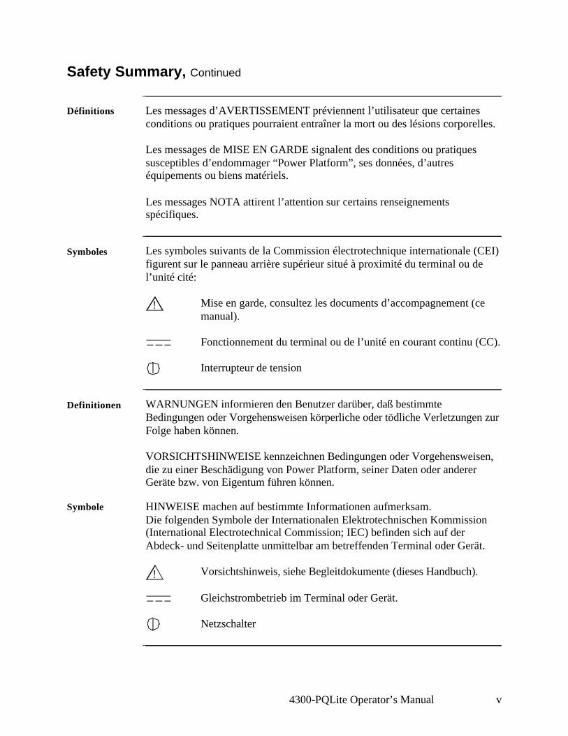
Définitions Les messages d’AVERTISSEMENT préviennent l’utilisateur que certaines conditions ou pratiques pourraient entraîner la mort ou des lésions corporelles.
Les messages de MISE EN GARDE signalent des conditions ou pratiques susceptibles d’endommager “Power Platform”, ses données, d’autres équipements ou biens matériels.
Les messages NOTA attirent l’attention sur certains renseignements spécifiques.
Symboles Les symboles suivants de la Commission électrotechnique internationale (CEI) figurent sur le panneau arrière supérieur situé à proximité du terminal ou de l’unité cité:
Mise en garde, consultez les documents d’accompagnement (ce manual).
Fonctionnement du terminal ou de l’unité en courant continu (CC).
Interrupteur de tension
Definitionen WARNUNGEN informieren den Benutzer darüber, daß bestimmte Bedingungen oder Vorgehensweisen körperliche oder tödliche Verletzungen zur Folge haben können.
VORSICHTSHINWEISE kennzeichnen Bedingungen oder Vorgehensweisen, die zu einer Beschädigung von Power Platform, seiner Daten oder anderer Geräte bzw. von Eigentum führen können.
Symbole HINWEISE machen auf bestimmte Informationen aufmerksam.Die folgenden Symbole der Internationalen Elektrotechnischen Kommission (International Electrotechnical Commission; IEC) befinden sich auf der Abdeck- und Seitenplatte unmittelbar am betreffenden Terminal oder Gerät.
Vorsichtshinweis, siehe Begleitdokumente (dieses Handbuch).
Gleichstrombetrieb im Terminal oder Gerät.
Netzschalter
!
!
vi 4300-PQLite Operator’s Manual
Safety Summary, Continued
Safety precautions
The following safety precautions must be followed whenever any type of voltage or current connection is being made to the 4300.• Wear proper Personal Protective Equipment, including safety glasses and
insulated gloves when making connections to power circuits.• Hands, shoes and floor must be dry when making any connection to a power
line.• Before each use, inspect all cables for breaks or cracks in the insulation.
Replace immediately if defective.• Set the 4300 power switch to Off.• Before connecting to electric circuits to be monitored, open their related
circuit breakers or disconnects. DO NOT install any connection of the 4300 to live power lines.
• Connections must be made to the 4300 first, then connect to the circuit to be monitored.
These safety precautions are repeated where appropriate throughout this manual.
4300-PQLite Operator’s Manual vii
Chapter Change No./Page No.
Title Cover 2
Prefaceii thru iii 2iv thru v 1vi thru viii 2ix 1x 2
Table of Contentsxi thru xiv 2xv 1
Chapter 11-1 thru 1-10 2
Chapter 22-1 thru 2-2 02-3 22-4 thru 2-6 0
Chapter 33-1 thru 3-2 23-3 13-4 thru 3-5 23-6 13-7 thru 3-14 23-15 13-16 23-17 13-18 23-19 thru 3-20 1
Chapter 44-1 thru 4-8 2
Chapter Change No./Page No.
Chapter 55-1 thru 5-5 15-6 25-7 15-8 thru 5-9 25-10 15-11 thru 5-12 25-13 thru 5-14 1
Chapter 66-1 16-2 26-3 16-4 thru 6-6 26-7 16-8 26-9 thru 6-10 16-11 26-12 16-13 thru 6-24 26-25 16-26 26-27 16-28 thru 6-30 2
Chapter 77-1 thru 7-4 17-5 thru 7-6 27-7/7-8 1
Chapter 88-1 thru 8-38 2
Appendix AA-1 thru A-12 2
CHANGE STATUS
Change No. 0: Original Issue: September 15, 1995.
Change No. 1: Revision A: January 15, 1997. Incorporating ECO 3313, 3458, 3459, 3499.
Change No. 2: Revision B: May 1, 2002. Incorporating ECO 16203, 16258, 16273, 16497, 16592, 16594, 16630.
LIST OF EFFECTIVE PAGES
viii 4300-PQLite Operator’s Manual
CHANGE STATUS
Change No. 0: Original Issue: September 15, 1995.
Change No. 1: Revision A: January 15, 1997. Incorporating ECO 3313, 3458, 3459, 3499.
Change No. 2: Revision B: May 1, 2002. Incorporating ECO 16203, 16258, 16273, 16497, 16592, 16594, 16630.
LIST OF EFFECTIVE PAGES
Chapter Change No./Page No.
Appendix BB-1 1B-2 2B-3 1B-4 thru B-5 2B-6 thru B-8 1
Appendix CC-1 thru C-9 1
Appendix DD-1 2
Appendix EE-1 thru E-4 1
Appendix FF-1 thru F-22 2
Appendix GG-1 thru G-4 2
Index1 thru 8 2
4300-PQLite Operator’s Manual ix
Statements and Notices
Statement of warranty
All products of Dranetz-BMI are warranted to the original purchaser against defective material and workmanship for a period of one year from the date of delivery. Dranetz-BMI will repair or replace, at its option, all defective equipment that is returned, freight prepaid, during the warranty period. There will be no charge for repair provided there is no evidence that the equipment has been mishandled or abused. This warranty shall not apply to any defects resulting from improper or inadequate maintenance, buyer-supplied hardware/software interfacing, unauthorized modification or misuse of the equipment, operation outside of environmental specifications, or improper site preparation or maintenance.
Statement of reliability
The information in this manual has been reviewed and is believed to be entirely reliable, however, no responsibility is assumed for any inaccuracies. All material is for informational purposes only and is subject to change without prior notice.
Notice regarding FCC compliance
This device has been tested and found to comply with the limits for a Class A digital device, pursuant to Part 15 of the FCC Rules. These limits are designed to provide reasonable protection against harmful interference when the equipment is operated in a commercial environment. This equipment generates, uses, and can radiate radio frequency energy and, if not installed and used in accordance with the instruction manual, may cause harmful interference to radio communications. Operation of this equipment in a residential area is likely to cause harmful interference in which case the user will be required to correct the interference at his/her own expense.
Notice regarding proprietary rights
This publication contains information proprietary to Dranetz-BMI. By accepting and using this manual, you agree that the information contained herein will be used solely for the purpose of operating equipment of Dranetz-BMI.
Continued on next page
x 4300-PQLite Operator’s Manual
Statements and Notices, Continued
Copyright This publication is protected under the Copyright laws of the United States, Title 17 et seq. No part of this publication may be reproduced, transmitted, transcribed, stored in a retrieval system, or translated into any language or computer language, in any form, by any means, electronic, mechanical, magnetic, optical, chemical, manual, or otherwise, without the prior written consent of Dranetz-BMI, 1000 New Durham Road, Edison, New Jersey 08818.
Copyright © 1995, 1997, 2002 Dranetz-BMIAll Rights Reserved. Printed in the United States of America.
Trademarks Power Platform, TASKCard, and Scope Mode are registered trademarks of Dranetz-BMI.
4300-PQLite Operator’s Manual xi
Table of Contents
Safety Summary......................................................................................................... ivStatements and Notices .............................................................................................. ix
CHAPTER 1 - Introduction
Overview.................................................................................................................... 1-1Unpacking The 4300.................................................................................................. 1-5Physical Description .................................................................................................. 1-6Operational Description ............................................................................................. 1-8
CHAPTER 2 - Controls, Indicators, and Connectors
Overview.................................................................................................................... 2-1Top and Front Panels ................................................................................................. 2-2Rear, Right, and Left Panels ...................................................................................... 2-4Bottom Panel.............................................................................................................. 2-6
CHAPTER 3 - Basic Operation
Overview.................................................................................................................... 3-1Power Requirements .................................................................................................. 3-2Installing a TASKCard .............................................................................................. 3-3Initial Power Turn On ................................................................................................ 3-4Common Screen Features .......................................................................................... 3-7Connecting Voltage Measurement Cables ................................................................. 3-8Connecting a Current Probe....................................................................................... 3-14
CHAPTER 4 - Scope and Meter Mode
Overview.................................................................................................................... 4-1Viewing Scope Mode................................................................................................. 4-2Viewing Meter Mode ................................................................................................. 4-4Viewing Voltage and Current Phasors....................................................................... 4-7Viewing Harmonics ................................................................................................... 4-8
CHAPTER 5 - Housekeeping Functions
Overview.................................................................................................................... 5-1Entering a Site Name ................................................................................................. 5-2Setting the Time and Date ......................................................................................... 5-4Setting the LCD Light, Audible Alarm and Language .............................................. 5-6Clearing Memory ....................................................................................................... 5-7Resetting the 4300 to the Factory Configuration ....................................................... 5-8Checking Site Status .................................................................................................. 5-11
xii 4300-PQLite Operator’s Manual
Table of Contents, Continued
Checking 4300 Status ................................................................................................ 5-12Running a Self-Test ................................................................................................... 5-13
CHAPTER 6 - Long-term Monitoring
Overview.................................................................................................................... 6-1Using Easy Start......................................................................................................... 6-3Turning Input Channels On and Off .......................................................................... 6-6Selecting Your Circuit Type ...................................................................................... 6-8Scale Factors .............................................................................................................. 6-10Entering Scale Factors ............................................................................................... 6-11Frequency Synchronization ....................................................................................... 6-13Setting Sync Parameters ............................................................................................ 6-15Changing the Timed Interval Setting ......................................................................... 6-17Editing Parameter Thresholds.................................................................................... 6-19Setting Waveform Capture ........................................................................................ 6-27Activating a Setup...................................................................................................... 6-29Turning Monitoring On ............................................................................................. 6-30
CHAPTER 7 - Saving Data
Overview.................................................................................................................... 7-1Setting Memory Storage Mode .................................................................................. 7-2Automatically Saving Data to a Memory Card ......................................................... 7-3Manually Saving Data to a Memory Card ................................................................. 7-5
CHAPTER 8 - Viewing Data
Overview.................................................................................................................... 8-1Section A -Copying Memory Card Files into Internal Memory ..................................... 8-3
Overview.................................................................................................................... 8-3Reading the Auto-Transfer File From a Memory Card ............................................. 8-5Reading an Event File from a Memory Card............................................................. 8-8
Section B -Graphic Summaries ....................................................................................... 8-9Overview.................................................................................................................... 8-9Viewing Time Plots ................................................................................................... 8-10Selecting a Parameter................................................................................................. 8-12Using Horizontal Zoom ............................................................................................. 8-13Changing the Vertical Scale ...................................................................................... 8-15Viewing the Event Activity Plot ................................................................................ 8-17
Section C -Events ............................................................................................................ 8-18Overview.................................................................................................................... 8-18Viewing the Event Report.......................................................................................... 8-19Event Descriptions ..................................................................................................... 8-20
4300-PQLite Operator’s Manual xiii
Table of Contents, Continued
Viewing Worst Case Events ...................................................................................... 8-23Viewing Event Details ............................................................................................... 8-25IEEE 1159 Classifications ......................................................................................... 8-26
Section D -Event Waveforms ......................................................................................... 8-27Overview.................................................................................................................... 8-27Viewing Event Waveforms........................................................................................ 8-28Analyzing Event Waveforms ..................................................................................... 8-30
Section E -Downloading Events from 4300 to a Computer ............................................ 8-32Hardware Requirements ............................................................................................ 8-33Software Requirements .............................................................................................. 8-34Connection Guidelines............................................................................................... 8-36Downloading Events .................................................................................................. 8-37
APPENDIX A - Optional Accessories
Overview.................................................................................................................... A-1Section A -Optional Accessories ..................................................................................... A-2
Overview.................................................................................................................... A-2Optional Accessories List .......................................................................................... A-3Optional Accessories Descriptions ............................................................................ A-5
Section B -CompactFlash Card........................................................................................ A-9Overview.................................................................................................................... A-9CompactFlash Card Power Features .......................................................................... A-10Using CompactFlash Card with the PP4300.............................................................. A-11Using CompactFlash Card with TASKCard PQLite V4.2 or higher ......................... A-12
APPENDIX B - Technical Specifications
Overview.................................................................................................................... B-1General ....................................................................................................................... B-2Interfaces.................................................................................................................... B-3Measured Parameters................................................................................................. B-4Computed Parameters ................................................................................................ B-6TR2500 Current Probe ............................................................................................... B-8
APPENDIX C - Battery Specifications and Replacement Procedure
Overview.................................................................................................................... C-1Battery Specifications ................................................................................................ C-2Battery Pack Safety Precautions ................................................................................ C-3Battery Pack Replacement ......................................................................................... C-5Memory Card Battery Replacement .......................................................................... C-7
APPENDIX D - Operator Replaceable Parts List
xiv 4300-PQLite Operator’s Manual
Table of Contents, Continued
APPENDIX E - System Messages
Overview.................................................................................................................... E-1Message Types........................................................................................................... E-2Messages .................................................................................................................... E-3
APPENDIX F - Common Circuit Connections
Overview.................................................................................................................... F-1Verifying Voltage and Current Connections ............................................................. F-5Single Phase ............................................................................................................... F-8Split Phase.................................................................................................................. F-9Four Wire Wye .......................................................................................................... F-10Floating or Grounded Delta ....................................................................................... F-11Open Leg Delta.......................................................................................................... F-13High-Leg Delta .......................................................................................................... F-14Connecting to a Potential Transformer (PT).............................................................. F-15Connecting to a Current Transformer (CT) ............................................................... F-17Connecting to an Isolated Current Transformer (ISO) .............................................. F-19
APPENDIX G - PQLite Menu Structure
Overview.................................................................................................................... G-1Scope/Meter Mode Menu .......................................................................................... G-2View Data Menu ........................................................................................................ G-3Setup Menu ................................................................................................................ G-4
INDEX
4300-PQLite Operator’s Manual xv
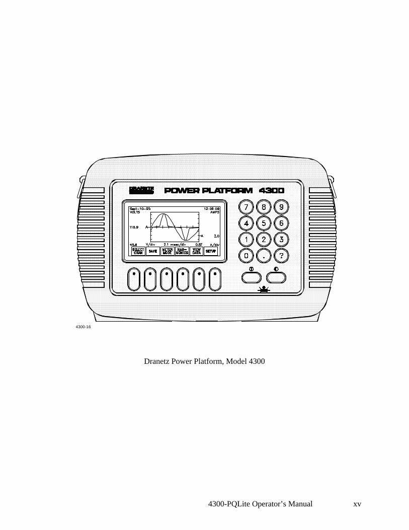
Dranetz Power Platform, Model 4300
4300-16

xvi 4300-PQLite Operator’s Manual
Introduction 1-1
Chapter 1
Introduction
Overview
4300 description The Dranetz Power Platform® Model 4300 is a portable, hand-held, TASKCard® based, eight-channel power quality meter/monitor. The 4300 can monitor, record and display data on four voltage channels and four current channels simultaneously. Data can be recorded and transferred to a personal or laptop computer using the Isolated Communications Module (P/N PP4300 RS232) and the DRAN-LINKTM 4300 utility software. The DRAN-LINKTM 4300 can download data from the unit’s internal memory or from an optional memory card. With TASKCard® PQLite V4.0 or higher, the 4300 can handle multi-lingual display of text and help screens. The help files are programmed for context sensitivity, displaying the appropriate help topics on specific errors commited. Context sensitive help is available in English, French, Italian, German and Spanish languages.
TASKCard definition
A TASKCard is a removable program card that is inserted in the 4300. Itcontains an operating system designed for a specific application (task).
Latest TASKCard® PQLite releases include V4.0 and V4.2.• TASKCard® PQLite V4.0 or higher offer upgrade features like Language
Selection and Scope Mode Timeout. See below for details on Language Selection and see page 4-2 for details on Scope Mode timeout.
• TASKCard® PQLite V4.2 or higher support the use of CompactFlash memory cards. CompactFlash is the new, performance versatile card replacing the old type of SRAM memory (data) cards. See page 1-10 for details.
Language Selection
TASKCard® PQLite V4.0 or higher support features such as Language Selection. Users now have the option to navigate the 4300 menu screens in any of the following languages: • English• French• Italian• German• Spanish
To select another language, see instructions on page 1-2.
Continued on next page
1-2 4300-PQLite Operator’s Manual
Overview, Continued
Language Selection (continued)
Follow these steps to select a new language.
Step Action
1 At start up, press SETUP from the SCOPE MODE screen.
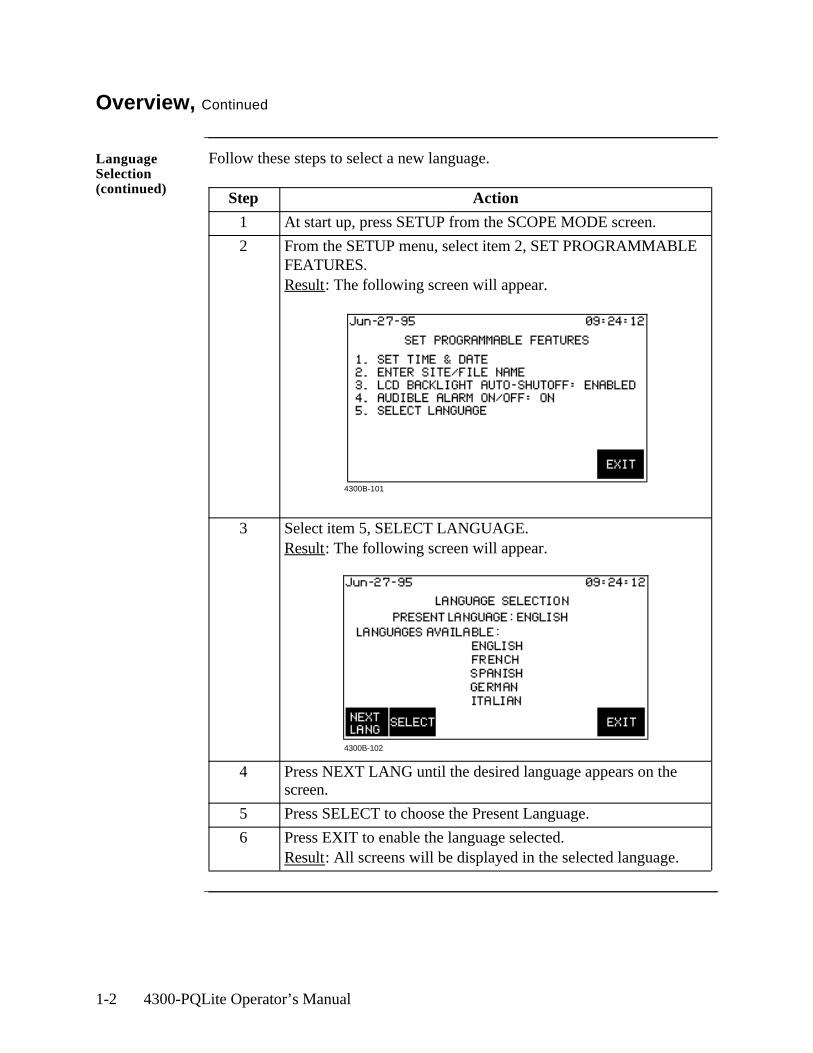
2 From the SETUP menu, select item 2, SET PROGRAMMABLE FEATURES. Result: The following screen will appear.
3 Select item 5, SELECT LANGUAGE. Result: The following screen will appear.
4 Press NEXT LANG until the desired language appears on the screen.
5 Press SELECT to choose the Present Language.
6 Press EXIT to enable the language selected.Result: All screens will be displayed in the selected language.
4300B-101
4300B-102
Introduction 1-3
Overview, Continued
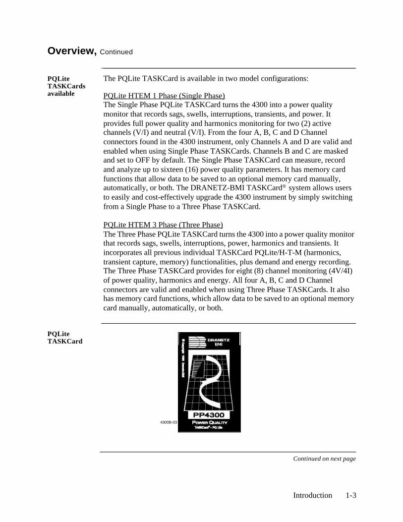
PQLite TASKCards available
The PQLite TASKCard is available in two model configurations:
PQLite HTEM 1 Phase (Single Phase)The Single Phase PQLite TASKCard turns the 4300 into a power quality monitor that records sags, swells, interruptions, transients, and power. It provides full power quality and harmonics monitoring for two (2) active channels (V/I) and neutral (V/I). From the four A, B, C and D Channel connectors found in the 4300 instrument, only Channels A and D are valid and enabled when using Single Phase TASKCards. Channels B and C are masked and set to OFF by default. The Single Phase TASKCard can measure, record and analyze up to sixteen (16) power quality parameters. It has memory card functions that allow data to be saved to an optional memory card manually, automatically, or both. The DRANETZ-BMI TASKCard® system allows users to easily and cost-effectively upgrade the 4300 instrument by simply switching from a Single Phase to a Three Phase TASKCard.
PQLite HTEM 3 Phase (Three Phase)The Three Phase PQLite TASKCard turns the 4300 into a power quality monitor that records sags, swells, interruptions, power, harmonics and transients. It incorporates all previous individual TASKCard PQLite/H-T-M (harmonics, transient capture, memory) functionalities, plus demand and energy recording. The Three Phase TASKCard provides for eight (8) channel monitoring (4V/4I) of power quality, harmonics and energy. All four A, B, C and D Channel connectors are valid and enabled when using Three Phase TASKCards. It also has memory card functions, which allow data to be saved to an optional memory card manually, automatically, or both.
PQLite TASKCard
Continued on next page
4300B-03

1-4 4300-PQLite Operator’s Manual
Overview, Continued
This manual This manual contains instructions for operating the Dranetz 4300 with any kind of PQLite TASKCard installed. Functions that are specific to each kind of TASKCard will be noted as such where they are discussed.
Specifically, functions specific to a Single Phase TASKCard are accompanied by the heading ! FOR SINGLE PHASE TASKCARD.
Where there is no reference made to a particular TASKCard, this means that the functionalities apply to both Single Phase and Three Phase TASKCards.
In this chapter The following topics are covered in this chapter.
Topic See Page
Unpacking the 4300 1-3
Physical Description 1-6
Operational Description 1-8
Introduction 1-5
Unpacking The 4300
Introduction For maximum protection against possible shipping damage, the 4300 has been sealed in a two-piece, plastic suspension pack, enclosed within a durable shipping carton. After opening the carton, inspect the contents for possible shipping damage and check the carton inventory.
Unpacking Unpack the 4300 from the carton as follows:
Shipping damage inspection
Visually inspect the 4300 for possible shipping damage. If any damage exists, first notify and file an insurance claim with your carrier or underwriter or both. Then notify Dranetz Customer Service Department of your intentions to return the unit. DO NOT return the 4300 without prior instructions from Dranetz Customer Service Department. Dranetz Customer Service Department can be reached at (732) 287-3680 or 1-800-DRANTEC.
Repacking for return shipment
If the unit must be returned to Dranetz for service or repair, wrap the unit securely in heavy packaging material and place in a well padded box or crate to prevent damage. Do not return the 4300 in an unpacked box. Dranetz Technologies Inc. will not be responsible for damage incurred during transit due to inadequate packing on your part.
Return notice Notify Dranetz Customer Service of your intention of returning the unit. Do not return the unit without prior instructions from Dranetz. Dranetz Customer Service Department can be reached at (732) 287-3680 or 1-800-DRANTEC.
Step Action
1 Remove any remaining literature inside the top of the carton.
2 Carefully remove the 4300 from its shipping carton.
3 Remove all accessories inside the carton. Check that all of the standard accessories (See next page) are included.
1-6 4300-PQLite Operator’s Manual
Physical Description
Dimensions The Dranetz 4300 is a self-contained, portable instrument weighing less than 5 pounds and measuring 8" (20.3 cm) deep by 12" (30.5 cm) wide by 2.5" (6.4 cm) high.
Top and front panels
The top panel contains the screen and keypad. The front panel contains two slots for holding a TASKCard and a memory card. See Chapter 2 for descriptions of the top and front panel controls and indicators, and connectors.
Rear and side panels
The rear panel contains the input voltage and current connectors. The left and right side panels contain the optical interface port and ac adapter input connector, respectively and rings for attaching the supplied carrying strap. See Chapter 2 for descriptions of the rear and side panel connectors.
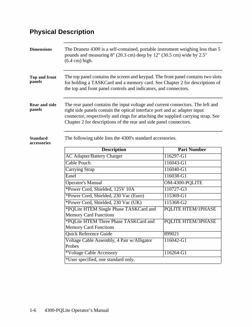
Standard accessories
The following table lists the 4300's standard accessories.
Description Part NumberAC Adapter/Battery Charger 116297-G1Cable Pouch 116043-G1Carrying Strap 116040-G1Easel 116038-G1Operator's Manual OM-4300-PQLITE*Power Cord, Shielded, 125V 10A 110727-G3*Power Cord, Shielded, 230 Vac (Euro) 115369-G1*Power Cord, Shielded, 230 Vac (UK) 115368-G2*PQLite HTEM Single Phase TASKCard and Memory Card Functions
PQLITE HTEM/1PHASE
*PQLite HTEM Three Phase TASKCard and Memory Card Functions
PQLITE HTEM/3PHASE
Quick Reference Guide 899021Voltage Cable Assembly, 4 Pair w/Alligator Probes
116042-G1
*Voltage Cable Accessory 116264-G1*User specified, one standard only.
Introduction 1-7
Physical Description, Continued
Optional accessories
The optional accessories are described in Appendix A.
Replaceable parts
Refer to Appendix D for operator replaceable parts.
Batteries Refer to Appendix C for the description and replacement of the batteries contained in the 4300.
Calibration The recommended calibration interval for this unit is once every 12 months.
We recommend that you return the unit to the factory for calibration. If you decide to do so, first contact the Dranetz Customer Service Department to obtain an Authorization Number.
Telephone: (732) 287-3680 or 1-800-DRANTECFAX: (732) 248-9240
Fill out the Repair/Service Order form enclosed in the shipping carton and ship it along with the unit to the Dranetz Repair Department. (If this form is missing, ask the Dranetz Customer Service Department for a replacement.)
1-8 4300-PQLite Operator’s Manual
Operational Description
Scope Mode The 4300 powers up in Scope Mode®. Scope Mode functions as an oscilloscope, displaying real-time waveforms of voltage and current for all channels.
Meter mode Meter mode provides the functions of a true RMS voltmeter and true RMS clamp-on ammeter. Voltage and current measurements, along with all other calculated parameters, are displayed on the Meter Mode screens.
The 4300 can also display voltage and current phasors for all of the channels. Functioning as a phase angle meter, the 4300 can display system imbalance conditions. The phase angle display can also verify that monitoring connections have been made correctly.
Monitoring capacity
The Dranetz 4300 can monitor any of the following power configurations:• Single phase, 2 wire• Split phase, 3 wire• 3 phase, 3 wire (delta)• 3 phase, 4 wire (wye)
While monitoring any of the above configurations (except delta), the 4300 can also be connected to monitor neutral to ground voltage and neutral or ground current.
Technical specifications
Specifications for the 4300, measured parameters, computed parameters, current probes, and isolated current transformers, are listed in Appendix B.
Easy Start The Easy Start function prompts you for information about the circuit you want to monitor and then automatically sets up the 4300 for monitoring. For complete information about operating Easy Start, see Chapter 6.
Setup The setup is a list of parameter thresholds that control the data recorded by the 4300.
Continued on next page
Introduction 1-9
Operational Description, Continued
Events An event is data that is stored in memory when a programmed threshold is crossed (either going out-of-limits or on return-to-normal), when a device is configured, or when system status changes.
Help Help is available by pressing the question mark (?) key on the numeric keypad. A help screen is a one page description of the screen (function) presently displayed.
Menu structure Refer to Appendix G for the menu structure of the PQLite TASKCard.
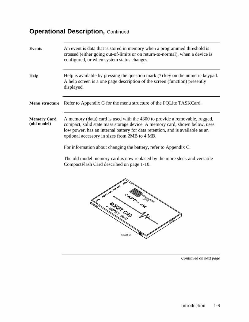
Memory Card (old model)
A memory (data) card is used with the 4300 to provide a removable, rugged, compact, solid state mass storage device. A memory card, shown below, uses low power, has an internal battery for data retention, and is available as an optional accessory in sizes from 2MB to 4 MB.
For information about changing the battery, refer to Appendix C.
The old model memory card is now replaced by the more sleek and versatile CompactFlash Card described on page 1-10.
Continued on next page
4300B-04
1-10 4300-PQLite Operator’s Manual
Operational Description, Continued
CompactFlash Memory Card (new model)
TASKCard® PQLite V4.2 or higher support the use of CompactFlash cards - a vastly improved replacement for old model memory cards that is now available for use with the PP4300.
The CompactFlash card has a more robust data handling and storage capability, and is available in sizes ranging from 8MB to 32MB. It can format and create data files in seconds. The card can accommodate up to 8 MB of auto-transfer files. Multiple auto-transfer files are possible in one card. CompactFlash is available to consumers at lower cost.
For information on how to use the CompactFlash card with PP4300 and TASKCard® PQLite V4.2, refer to Appendix A - Section B on page A-9.
Controls, Indicators, and Connectors 2-1
Chapter 2
Controls, Indicators, and Connectors
Overview
Introduction This chapter identifies and describes the controls, indicators, and connectors on all panels of the 4300.
In this chapter The following topics are covered in this chapter.
Topic See Page
Top and Front Panels 2-2
Rear, Right, and Left Panels 2-4
Bottom Panel 2-6
2-2 4300-PQLite Operator’s Manual
Top and Front Panels
Diagram
Continued on next page
4300-17
Controls, Indicators, and Connectors 2-3
Top and Front Panels, Continued
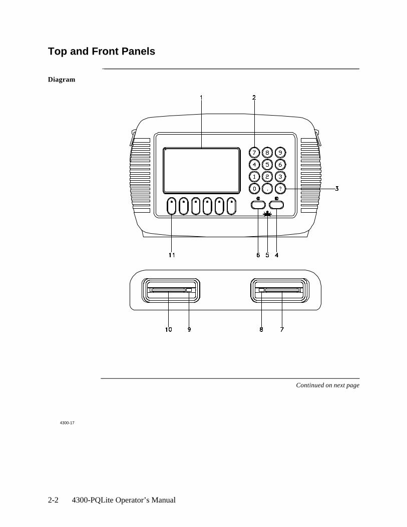
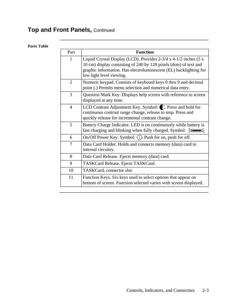
Parts Table
Part Function
1 Liquid Crystal Display (LCD). Provides 2-3/4 x 4-1/2 inches (5 x 10 cm) display consisting of 240 by 128 pixels (dots) of text and graphic information. Has electroluminescent (EL) backlighting for low light level viewing.
2 Numeric keypad. Consists of keyboard keys 0 thru 9 and decimal point (.) Permits menu selection and numerical data entry.
3 Question Mark Key. Displays help screen with reference to screen displayed at any time.
4 LCD Contrast Adjustment Key. Symbol: . Press and hold for continuous contrast range change, release to stop. Press and quickly release for incremental contrast change.
5 Battery Charge Indicator. LED is on continuously while battery is fast charging and blinking when fully charged. Symbol:
6 On/Off Power Key. Symbol: . Push for on, push for off.
7 Data Card Holder. Holds and connects memory (data) card to internal circuitry.
8 Data Card Release. Ejects memory (data) card.
9 TASKCard Release. Ejects TASKCard.
10 TASKCard, connector slot.
11 Function Keys. Six keys used to select options that appear on bottom of screen. Function selected varies with screen displayed.
2-4 4300-PQLite Operator’s Manual
Rear, Right, and Left Panels
Diagram
Continued on next page
4300-18

Controls, Indicators, and Connectors 2-5
Rear, Right, and Left Panels, Continued
Parts Table
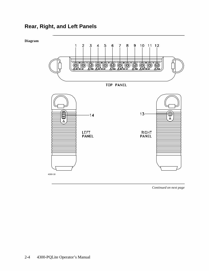
Part Description
1 CH A, + Differential Voltage Input Connector; color red.
2 CH A, - Differential Voltage Input Connector; color white.
3 CH A, PROBE, Current Input Connector.
4 CH B, + Differential Voltage Input Connector; color yellow.
5 CH B, - Differential Voltage Input Connector; color white.
6 CH B, PROBE, Current Input Connector.
7 CH C, + Differential Voltage Input Connector; color blue.
8 CH C, - Differential Voltage Input Connector; color white.
9 CH C, PROBE, Current Input Connector.
10 CH D, + Differential Voltage Input Connector; color grey.
11 CH D, - Differential Voltage Input Connector; color white.
12 CH D, PROBE, Current Input Connector.
13 AC Adapter/Battery Charger Input Connector.
14 Optical Serial Data Port.
2-6 4300-PQLite Operator’s Manual
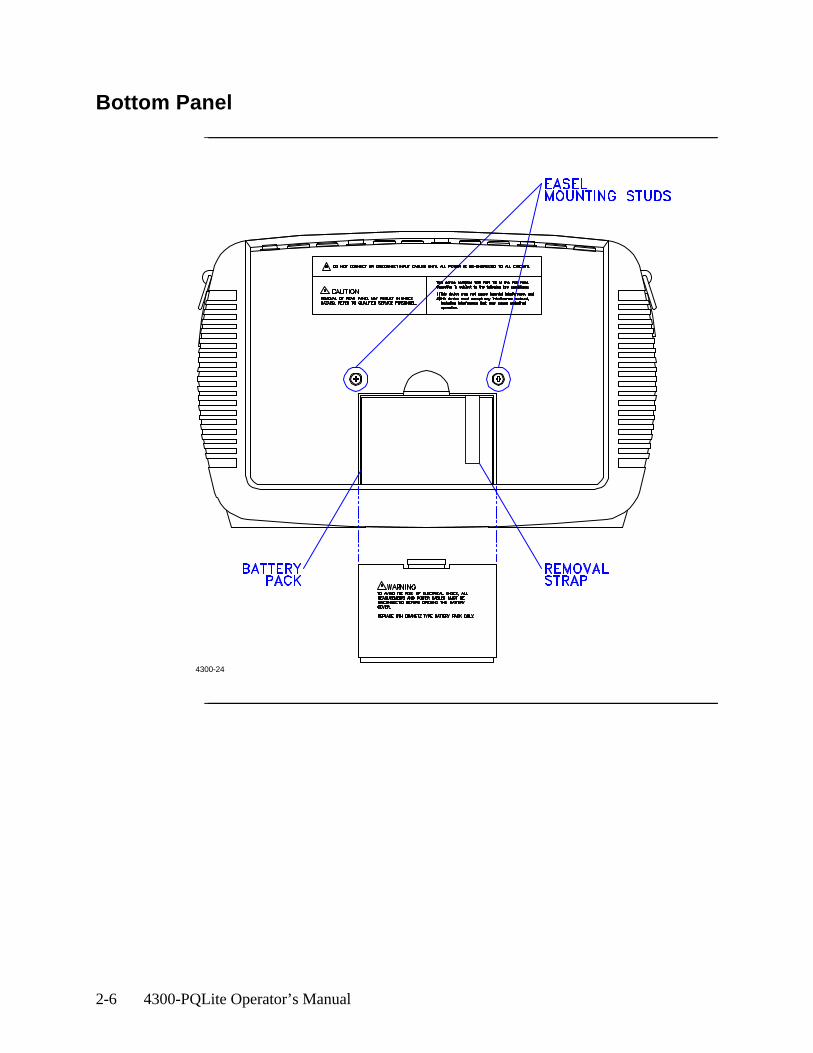
Bottom Panel
4300-24
Basic Operation 3-1
Chapter 3
Basic Operation
Overview
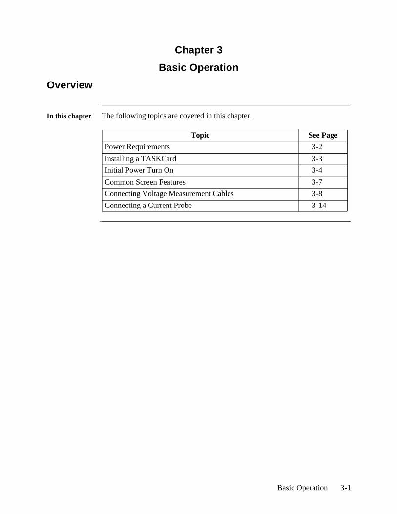
In this chapter The following topics are covered in this chapter.
Topic See Page
Power Requirements 3-2
Installing a TASKCard 3-3
Initial Power Turn On 3-4
Common Screen Features 3-7
Connecting Voltage Measurement Cables 3-8
Connecting a Current Probe 3-14

3-2 4300-PQLite Operator’s Manual
Power Requirements
Introduction The normal power source for the 4300 is its internal battery pack. The AC Adapter/Battery Charger is used to charge the battery. Always charge the battery fully before use. The 4300 will always operate on the charger and is designed to do so, regardless of the state of charge of the battery.
Battery pack Length of operation: The 4300 can operate on a fully charged battery pack for up to four hours. A screen warning will appear during operation when battery charge is low.
Charging: The battery pack can be charged by connecting the AC Adapter/Battery Charger to the 4300. A depleted battery pack can be recharged in two hours with the unit off and twenty-four hours with the unit on. The Battery Charge Indicator glows steadily while charging, and flashes when fully charged.
NOTE: The Battery Charge Indicator functions only when the unit is turned OFF and the AC Adapter/Battery Charger is properly connected.
AC power source
The 4300 can be operated from a 50/60 Hz ac power source with or without the battery pack installed.
Connect the AC Adapter output cable to the Input Connector on the right side of the PP4300. Connect the AC Adapter power cord to an appropriate outlet.
WARNING: Refer to the next sections Connecting Voltage Measurement Cables and Connecting a Current Probe, and refer to Appendix F Common Circuit Connections, for detailed descriptions of common power monitoring configurations and cable connections.
Basic Operation 3-3
Installing a TASKCard
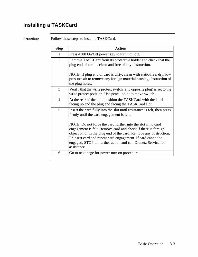
Procedure Follow these steps to install a TASKCard.
Step Action
1 Press 4300 On/Off power key to turn unit off.
2 Remove TASKCard from its protective holder and check that the plug end of card is clean and free of any obstruction.
NOTE: If plug end of card is dirty, clean with static-free, dry, low pressure air to remove any foreign material causing obstruction of the plug holes.
3 Verify that the write protect switch (end opposite plug) is set to the write protect position. Use pencil point to move switch.
4 At the rear of the unit, position the TASKCard with the label facing up and the plug end facing the TASKCard slot.
5 Insert the card fully into the slot until resistance is felt, then press firmly until the card engagement is felt.
NOTE: Do not force the card further into the slot if no card engagement is felt. Remove card and check if there is foreign object on or in the plug end of the card. Remove any obstruction. Reinsert card and repeat card engagement. If card cannot be engaged, STOP all further action and call Dranetz Service for assistance.
6 Go to next page for power turn on procedure.
3-4 4300-PQLite Operator’s Manual
Initial Power Turn On
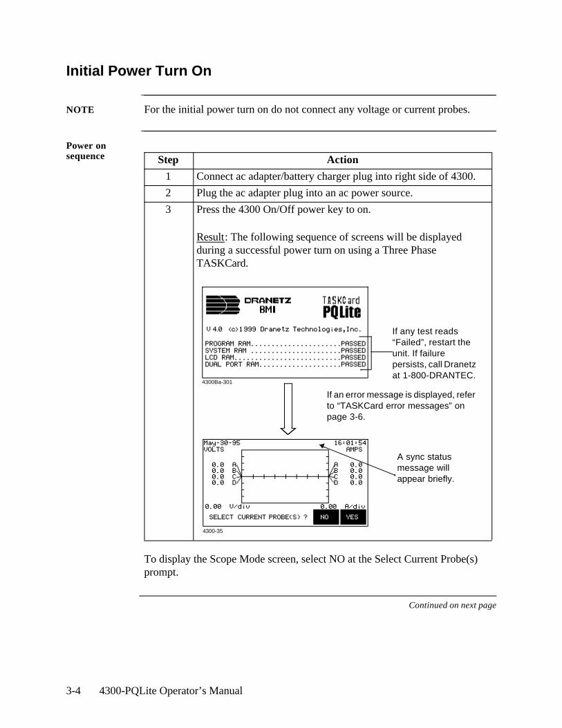
NOTE For the initial power turn on do not connect any voltage or current probes.
Power on sequence
To display the Scope Mode screen, select NO at the Select Current Probe(s) prompt.
Continued on next page
Step Action
1 Connect ac adapter/battery charger plug into right side of 4300.
2 Plug the ac adapter plug into an ac power source.
3 Press the 4300 On/Off power key to on.
Result: The following sequence of screens will be displayed during a successful power turn on using a Three Phase TASKCard.
If any test reads “Failed”, restart the unit. If failure persists, call Dranetz at 1-800-DRANTEC.
A sync status message will appear briefly.
4300Ba-301
4300-35
If an error message is displayed, refer to “TASKCard error messages” on page 3-6.
Basic Operation 3-5
Initial Power Turn On, Continued
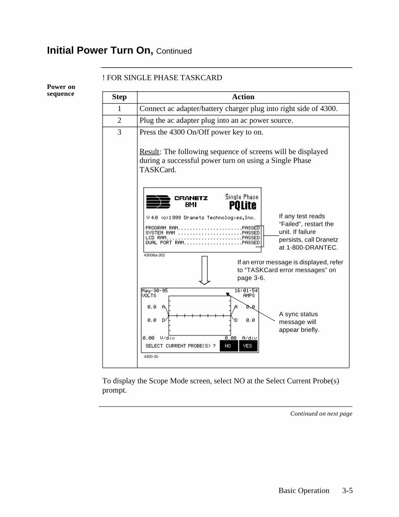
! FOR SINGLE PHASE TASKCARDPower on sequence
To display the Scope Mode screen, select NO at the Select Current Probe(s) prompt.
Continued on next page
Step Action
1 Connect ac adapter/battery charger plug into right side of 4300.
2 Plug the ac adapter plug into an ac power source.
3 Press the 4300 On/Off power key to on.
Result: The following sequence of screens will be displayed during a successful power turn on using a Single Phase TASKCard.
If any test reads “Failed”, restart the unit. If failure persists, call Dranetz at 1-800-DRANTEC.
A sync status message will appear briefly.
4300Ba-302
4300-35
If an error message is displayed, refer to “TASKCard error messages” on page 3-6.
3-6 4300-PQLite Operator’s Manual
Initial Power Turn On, Continued
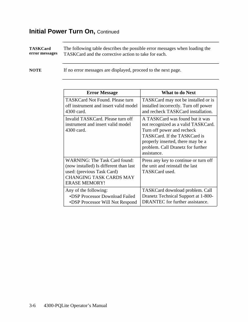
TASKCard error messages
The following table describes the possible error messages when loading the TASKCard and the corrective action to take for each.
NOTE If no error messages are displayed, proceed to the next page.
Error Message What to do Next
TASKCard Not Found. Please turn off instrument and insert valid model 4300 card.
TASKCard may not be installed or is installed incorrectly. Turn off power and recheck TASKCard installation.
Invalid TASKCard. Please turn off instrument and insert valid model 4300 card.
A TASKCard was found but it was not recognized as a valid TASKCard. Turn off power and recheck TASKCard. If the TASKCard is properly inserted, there may be a problem. Call Dranetz for further assistance.
WARNING: The Task Card found: (now installed) Is different than last used: (previous Task Card) CHANGING TASK CARDS MAY ERASE MEMORY!
Press any key to continue or turn off the unit and reinstall the last TASKCard used.
Any of the following:•DSP Processor Download Failed•DSP Processor Will Not Respond
TASKCard download problem. Call Dranetz Technical Support at 1-800-DRANTEC for further assistance.
Basic Operation 3-7
Common Screen Features
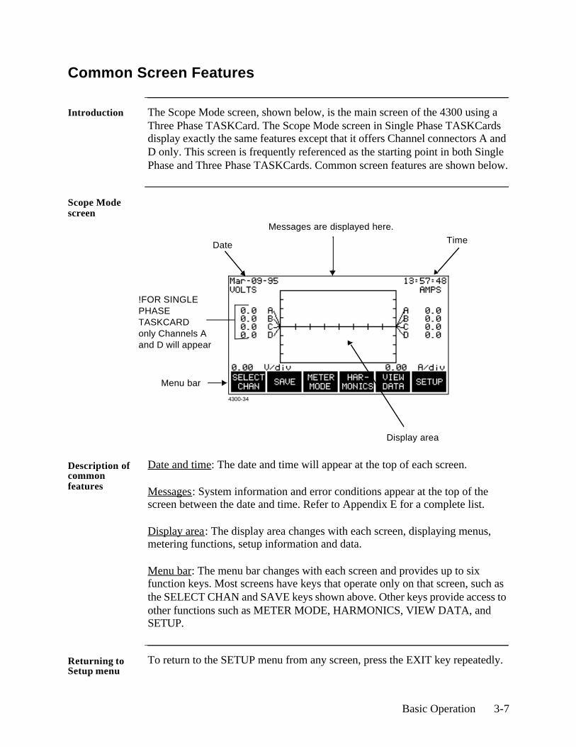
Introduction The Scope Mode screen, shown below, is the main screen of the 4300 using a Three Phase TASKCard. The Scope Mode screen in Single Phase TASKCards display exactly the same features except that it offers Channel connectors A and D only. This screen is frequently referenced as the starting point in both Single Phase and Three Phase TASKCards. Common screen features are shown below.
Scope Mode screen
Description of common features
Date and time: The date and time will appear at the top of each screen.
Messages: System information and error conditions appear at the top of the screen between the date and time. Refer to Appendix E for a complete list.
Display area: The display area changes with each screen, displaying menus, metering functions, setup information and data.
Menu bar: The menu bar changes with each screen and provides up to six function keys. Most screens have keys that operate only on that screen, such as the SELECT CHAN and SAVE keys shown above. Other keys provide access to other functions such as METER MODE, HARMONICS, VIEW DATA, and SETUP.
Returning to Setup menu
To return to the SETUP menu from any screen, press the EXIT key repeatedly.
Date
Messages are displayed here.
Menu bar
Time
Display area
4300-34
!FOR SINGLE PHASE TASKCARD only Channels A and D will appear
3-8 4300-PQLite Operator’s Manual
Connecting Voltage Measurement Cables
Introduction This section describes how to connect the 4300 to make basic single phase voltage measurements. For multi-phase connection diagrams, refer to Appendix F.
WARNING Death, serious injury, or fire hazard could result from improper connection of this instrument. Read and understand this manual before connecting this instrument. Follow all installation and operating instructions while using this instrument.
Connection of this instrument must be performed in compliance with the National Electrical Code (ANSI/NFPA 70-2002) and any additional safety requirements applicable to your installation.
Installation, operation, and maintenance of this instrument must be performed by qualified personnel only. The National Electrical Code defines a qualified person as “one who has the skills and knowledge related to the construction and operation of the electrical equipment and installations, and who has received safety training on the hazards involved.”
Qualified personnel who work on or near exposed energized electrical conductors must follow applicable safety related work practices and procedures including appropriate personal protective equipment in compliance with the Standard for Electrical Safety Requirements for Employee Workplaces (ANSI/NFPA 70E-2000) of USA and any additional workplace safety requirements applicable to your installation.
ADVERTEN-CIA
Una conexión incorrecta de este instrumento puede producir la muerte, lesiones graves y riesgo de incendio. Lea y entienda este manual antes de conectar. Observe todas las instrucciones de instalación y operación durante el uso de este instrumento.
La conexión de este instrumento debe ser hecha de acuerdo con las normas del Código Eléctrico Nacional (ANSI/NFPA 70-2002) de EE. UU., además de cualquier otra norma de seguridad correspondiente a su establecimiento.
La instalación, operación y mantenimiento de este instrumento debe ser realizada por personal calificado solamente. El Código Eléctrico Nacional define a una persona calificada como "una que esté familiarizada con la construcción y operación del equipo y con los riesgos involucrados."
Continued on next page

Basic Operation 3-9
Connecting Voltage Measurement Cables, Continued
AVERTISSE-MENT
Si l'instrument est mal connecté, la mort, des blessures graves, ou un danger d'incendie peuvent s'en suivre. Lisez attentivement ce manuel avant de connecter l'instrument. Lorsque vous utilisez l'instrument, suivez toutes les instructions d'installation et de service.
Cet instrument doit être connecté conformément au National Electrical Code (ANSI/NFPA 70-2002) des Etats-Unis et à toutes les exigences de sécurité applicables à votre installation.
Cet instrument doit être installé, utilisé et entretenu uniquement par un personnel qualifié. Selon le National Electrical Code, une personne est qualifiée si "elle connaît bien la construction et l'utilisation de l'équipement, ainsi que les dangers que cela implique."
WARNUNG Der falsche Anschluß dieses Gerätes kann Tod, schwere Verletzungen oder Feuer verursachen. Bevor Sie dieses Instrument anschließen, müssen Sie die Anleitung lesen und verstanden haben. Bei der Verwendung dieses Instruments müssen alle Installation- und Betriebsanweisungen beachtet werden.
Der Anschluß dieses Instruments muß in Übereinstimmung mit den nationalen Bestimmungen für Elektrizität (ANSI/NFPA 70-2002) der Vereinigten Staaten, sowie allen weiteren, in Ihrem Fall anwendbaren Sicherheitsbestimmungen, vorgenommen werden.
Installation, Betrieb und Wartung dieses Instruments dürfen nur von Fachpersonal durchgeführt werden. In dem nationalen Bestimmungen für Elektrizität wird ein Fachmann als eine Person bezeichnet, welche "mit der Bauweise und dem Betrieb des Gerätes sowie den dazugehörigen Gefahren vertraut ist."
Continued on next page

3-10 4300-PQLite Operator’s Manual
Connecting Voltage Measurement Cables, Continued
WARNING To avoid the risk of electric shock or burns, always connect the safety (or earth) ground before making any other connections.
WARNING To reduce the risk of fire, electrical shock, or physical injury it is strongly recommended to fuse the voltage measurement inputs.Fuses must be located as close to the load as possible to maximize protection.
WARNING For continued protection against risk of fire or shock hazard replace only with same type and rating of recommended fuse.Use only fast blow type fuse which is rated 600V. Recommended fuse type is Littelfuse, part number KLKD0.25 rated 600V AC/DC, 0.25 A fast blow.
WARNING Do not replace fuse again if failure is repeated. Repeated failure indicates a defective condition that will not clear with replacement of the fuse. Refer condition to a qualified technician.
Safety precautions
The following safety precautions must be followed whenever any type ofvoltage or current connection is being made to the 4300.
• Wear proper Personal Protective Equipment, including safety glasses and insulated gloves when making connections to power circuits.
• Hands, shoes and floor must be dry when making any connection to a power line.
• Before each use, inspect all cables for breaks or cracks in the insulation. Replace immediately if defective.
• Press the 4300 On/Off power key to Off.• Before connecting to electric circuits to be monitored, open their related
circuit breakers or disconnects. DO NOT install any connection of the 4300 to live power lines.
• Connections must be made to the 4300 first, then connect to the circuit to be monitored.
Continued on next page
Basic Operation 3-11
Connecting Voltage Measurement Cables, Continued
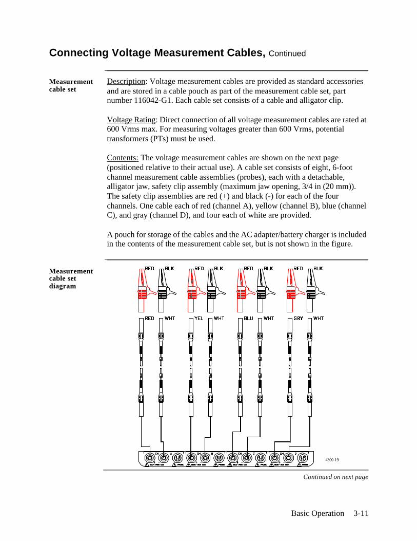
Measurement cable set
Description: Voltage measurement cables are provided as standard accessories and are stored in a cable pouch as part of the measurement cable set, part number 116042-G1. Each cable set consists of a cable and alligator clip.
Voltage Rating: Direct connection of all voltage measurement cables are rated at 600 Vrms max. For measuring voltages greater than 600 Vrms, potential transformers (PTs) must be used.
Contents: The voltage measurement cables are shown on the next page (positioned relative to their actual use). A cable set consists of eight, 6-foot channel measurement cable assemblies (probes), each with a detachable, alligator jaw, safety clip assembly (maximum jaw opening, 3/4 in (20 mm)). The safety clip assemblies are red (+) and black (-) for each of the four channels. One cable each of red (channel A), yellow (channel B), blue (channel C), and gray (channel D), and four each of white are provided.
A pouch for storage of the cables and the AC adapter/battery charger is included in the contents of the measurement cable set, but is not shown in the figure.
Measurement cable set diagram
Continued on next page
4300-19
3-12 4300-PQLite Operator’s Manual
Connecting Voltage Measurement Cables, Continued
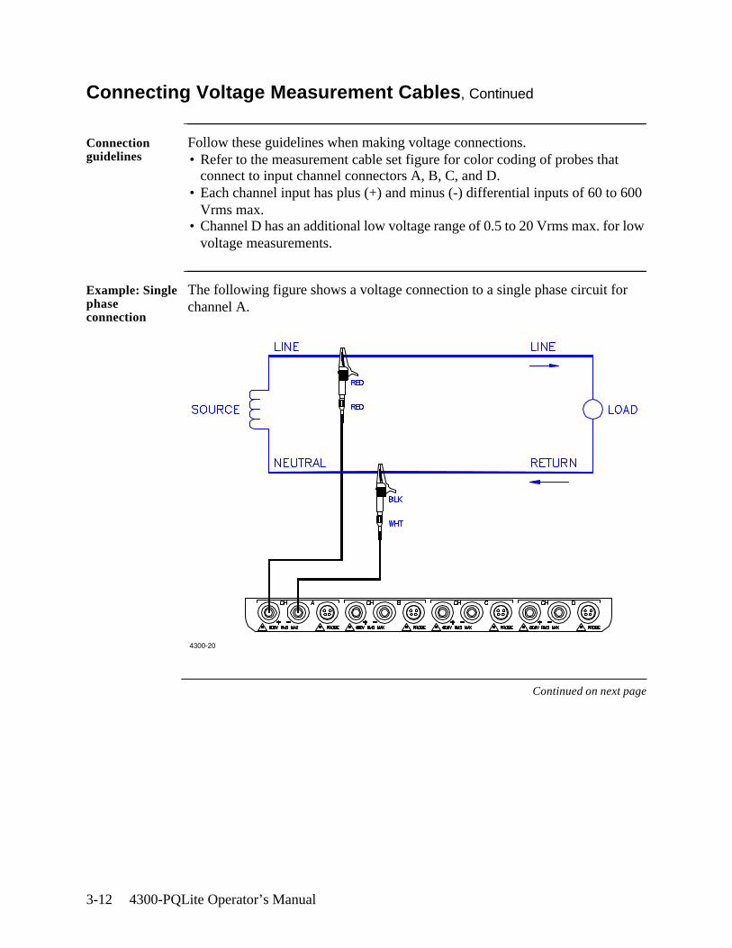
Connection guidelines
Follow these guidelines when making voltage connections.• Refer to the measurement cable set figure for color coding of probes that
connect to input channel connectors A, B, C, and D.• Each channel input has plus (+) and minus (-) differential inputs of 60 to 600
Vrms max.• Channel D has an additional low voltage range of 0.5 to 20 Vrms max. for low
voltage measurements.
Example: Single phase connection
The following figure shows a voltage connection to a single phase circuit for channel A.
Continued on next page
4300-20
Basic Operation 3-13
Connecting Voltage Measurement Cables, Continued
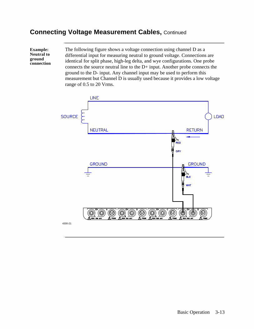
Example: Neutral to ground connection
The following figure shows a voltage connection using channel D as a differential input for measuring neutral to ground voltage. Connections are identical for split phase, high-leg delta, and wye configurations. One probe connects the source neutral line to the D+ input. Another probe connects the ground to the D- input. Any channel input may be used to perform this measurement but Channel D is usually used because it provides a low voltage range of 0.5 to 20 Vrms.
4300-21
3-14 4300-PQLite Operator’s Manual
Connecting a Current Probe
Safety precautions
The following safety precautions apply to current probe connections in addition to those safety precautions stated on page 3-10.• DO NOT attempt to measure current in any circuit in which the circuit to
ground voltage exceeds the insulation rating of the current probe (600 Vrms max).
• Make sure the jaws of the current probe are tightly closed. Keep mating surfaces clean and free from foreign matter.
WARNING When using the TR2021, TR2021A or TR2510 current probe, DO NOT clamp the probe jaws around a non-insulated wire. These probes are designed for use around insulated wire only.
ADVERTEN-CIA
Cuando utilice sondas de corriente TR2021, TR2021A o TR2510 NO sujete las mordazas de la sonda alrededor de un alambre sin aislamiento. Estas sondas están diseñadas para usarse alrededor de cables aislados únicamente.
AVERTISSE-MENT
Lorsque vous utilisez la sonde de courant TR2021, TR2021A ou TR2510, NE CLAMPEZ PAS les mâchoires de la sonde autour d’un fil non isolé. Ces sondes sont conçues pour emploi exclusif autour de fils isolés.
WARNUNG Bei der Verwendung der Stromsonde TR2021, TR2021A oder TR2510 die Sondenbacken NICHT um einen nicht isolierten Draht klemmen. Diese Sonden sind nur für den Einsatz um isolierten Draht vorgesehen.
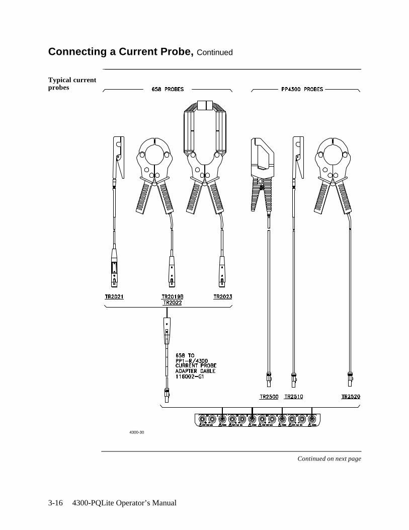
Current probes Several Dranetz current probes can be used with the 4300. Typical current probes are illustrated on the following page. Refer to Appendix A for descriptions and part numbers for probes and adapter cables. Refer to Appendix B for specifications for model TR2500.
NOTE: The TR2500 can perform all current measurements except transient detection.
Continued on next page
Basic Operation 3-15
Connecting a Current Probe, Continued
Current probes (continued)
Probe positioning: An arrow marking on the handle is a guide to ensure that you position the probe with the arrow pointing towards the load when monitoring the line conductor. Correct position of the probe is necessary for correct power measurements, where in-phase voltage and current measurements are necessary. A positive watts reading indicates that the probe is pointed towards the load, and a negative reading indicates that the probe is pointed towards the source.
Reference to channel input
Because no reference at the probe end identifies which channel is being monitored, a wire marker kit is supplied as a standard accessory to help in probe/channel identification. This kit, part number 155520, provides color-coded channel marker labels to attach to both the probe handle and the plug end of the probe.
Continued on next page
3-16 4300-PQLite Operator’s Manual
Connecting a Current Probe, Continued
Typical current probes
Continued on next page
4300-30
Basic Operation 3-17
Connecting a Current Probe, Continued
Connection guidelines
Follow these guidelines when making current connections.• Position the probe with the arrow on the handle pointing towards the load.• For greatest accuracy, use a probe that is rated at no more than twice the
nominal value you expect to measure.
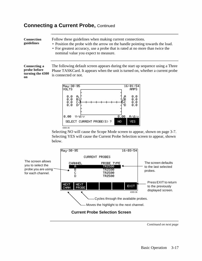
Connecting a probe before turning the 4300 on
The following default screen appears during the start up sequence using a Three Phase TASKCard. It appears when the unit is turned on, whether a current probe is connected or not.
Selecting NO will cause the Scope Mode screen to appear, shown on page 3-7.Selecting YES will cause the Current Probe Selection screen to appear, shown below.
Continued on next page
4300-35
Cycles through the available probes.
Moves the highlight to the next channel.
The screen allows you to select the probe you are using for each channel.
Press EXIT to return to the previously displayed screen.
4300-36
The screen defaults to the last selected probes.
Current Probe Selection Screen

3-18 4300-PQLite Operator’s Manual
Connecting a Current Probe, Continued
! FOR SINGLE PHASE TASKCARD
Connecting a probe before turning the 4300 on
The following default screen appears during the start up sequence using a Single Phase TASKCard. It appears when the unit is turned on, whether a current probe is connected or not.
Selecting NO will cause the Scope Mode screen to appear, shown on page 3-7.Selecting YES will cause the Current Probe Selection screen to appear, shown below.
Continued on next page
4300B-303
Cycles through the available probes.
Moves the highlight to the next channel.
The screen allows you to select the probe you are using for channels A and D.
Press EXIT to return to the previously displayed screen.
4300B-304
The screen defaults to the last selected probes.
Current Probe Selection Screen
Basic Operation 3-19
Connecting a Current Probe, Continued
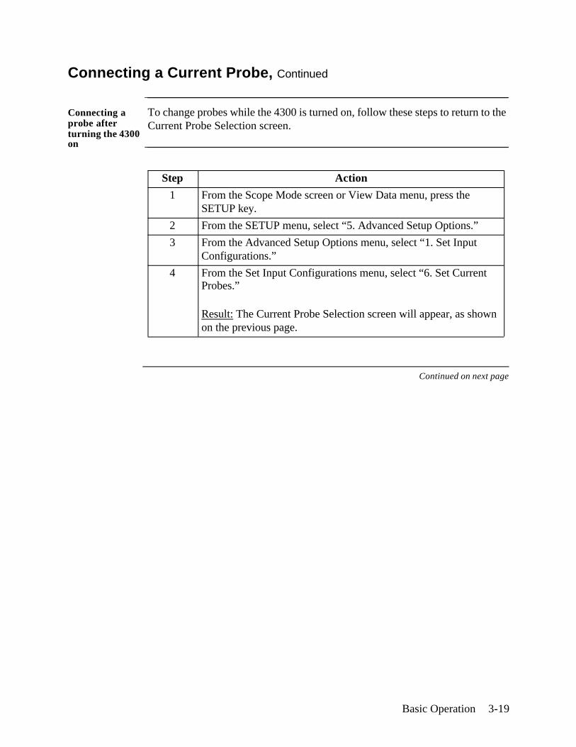
Connecting a probe after turning the 4300 on
To change probes while the 4300 is turned on, follow these steps to return to the Current Probe Selection screen.
Continued on next page
Step Action
1 From the Scope Mode screen or View Data menu, press the SETUP key.
2 From the SETUP menu, select “5. Advanced Setup Options.”
3 From the Advanced Setup Options menu, select “1. Set Input Configurations.”
4 From the Set Input Configurations menu, select “6. Set Current Probes.”
Result: The Current Probe Selection screen will appear, as shown on the previous page.
3-20 4300-PQLite Operator’s Manual
Connecting a Current Probe, Continued
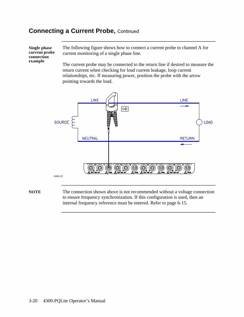
Single phase current probe connection example
The following figure shows how to connect a current probe to channel A for current monitoring of a single phase line.
The current probe may be connected to the return line if desired to measure the return current when checking for load current leakage, loop current relationships, etc. If measuring power, position the probe with the arrow pointing towards the load.
NOTE The connection shown above is not recommended without a voltage connection to ensure frequency synchronization. If this configuration is used, then an internal frequency reference must be entered. Refer to page 6-15.
4300-22
Scope and Meter Mode 4-1
Chapter 4
Scope and Meter Mode
Overview
Introduction This chapter describes the operation of scope and meter modes, which allow you to view real-time voltage and current waveforms; values for 16 parameters; voltage and current phasors; and harmonics displays for up to the 50th harmonic.
In this chapter The following topics are covered in this chapter.
Topic See Page
Viewing Scope Mode 4-2
Viewing Meter Mode 4-4
Viewing Voltage and Current Phasors 4-7
Viewing Harmonics 4-8
4-2 4300-PQLite Operator’s Manual
Viewing Scope Mode
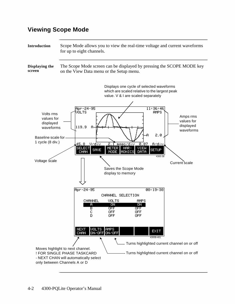
Introduction Scope Mode allows you to view the real-time voltage and current waveforms for up to eight channels.
Displaying the screen
The Scope Mode screen can be displayed by pressing the SCOPE MODE key on the View Data menu or the Setup menu.
Volts rms values for displayed waveforms
Amps rms values for displayed waveforms
Displays one cycle of selected waveforms which are scaled relative to the largest peak value. V & I are scaled separately
Saves the Scope Mode display to memory
Turns highlighted current channel on or off
Turns highlighted current channel on or offMoves highlight to next channel.! FOR SINGLE PHASE TASKCARD- NEXT CHAN will automatically select only between Channels A or D
Voltage scale Current scale
4300-38
4300B-401
Baseline scale for 1 cycle (8 div.)
Scope and Meter Mode 4-3
Viewing Scope Mode, Continued
Scope Mode timeout
The Scope Mode screen will automatically time out and return to the main menu after 15 minutes of no user activity. The display timeout reduces the possibility of Scope Mode-induced problems and ensures proper energy monitoring.
USERS ARE ADVISED NOT TO LEAVE THE UNIT IN SCOPE MODE WHILE MONITORING IS ON. Prolonged Scope Mode screen display causes problems because it grabs and holds data resource and uses a huge amount of processor time. While in Scope Mode, the instrument may not capture and accumulate energy settings accurately. Scope Mode is designed to provide real-time information on voltage and current waveforms; it is not designed to monitor events.

4-4 4300-PQLite Operator’s Manual
Viewing Meter Mode
Types of display The 4300 has four meter screens: the first three display real-time values for sixteen parameters and the fourth displays phasors. The first three screens contain the same information but in different formats.
Displaying the screen
The Meter Mode screen can be displayed by pressing the METER MODE key on the Scope Mode screen, View Data menu, or Setup menu. The screens below appear when using a Three Phase TASKCard.
Continued on next page
Displays groups in the following order:VoltAmpWattVAVARPFHzV UnbVthdIthdICFKFDemandEnergyV HnnI Hnn
Saves all meter, phasor, and harmonic values to memory
Select the circuit type you are measuring so that watts, VAs, VARs, and PF will be calculated correctly
Values are updated once per secondFor delta circuits,
the designations are A-B, B-C, C-A
Refer to page4-7 for screen description
4300-40
4300-41
4300-42
4300-43
4300-44
Scope and Meter Mode 4-5
Viewing Meter Mode, Continued
! FOR SINGLE PHASE TASKCARD
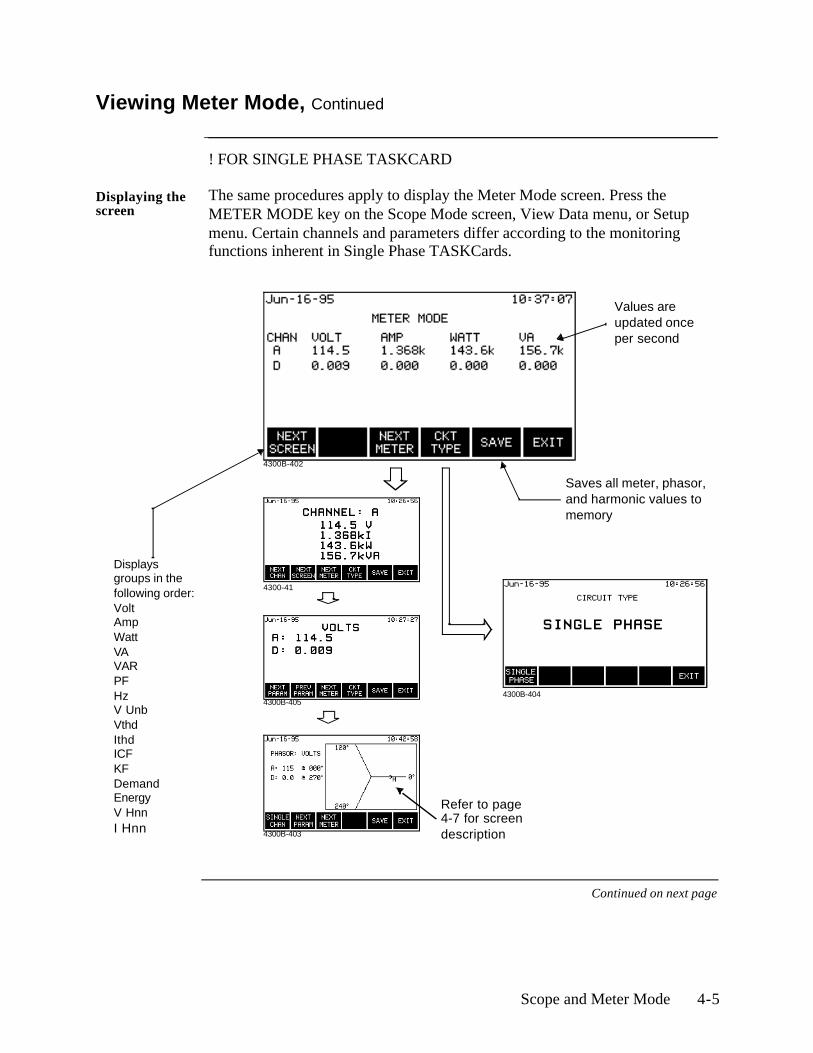
Displaying the screen
The same procedures apply to display the Meter Mode screen. Press the METER MODE key on the Scope Mode screen, View Data menu, or Setup menu. Certain channels and parameters differ according to the monitoring functions inherent in Single Phase TASKCards.
Continued on next page
4300B-405
4300B-402
4300B-403
Displays groups in the following order:VoltAmpWattVAVARPFHzV UnbVthdIthdICFKFDemandEnergyV HnnI Hnn
Saves all meter, phasor, and harmonic values to memory
Values are updated once per second
Refer to page4-7 for screen description
4300-41
4300B-404
4-6 4300-PQLite Operator’s Manual
Viewing Meter Mode, Continued
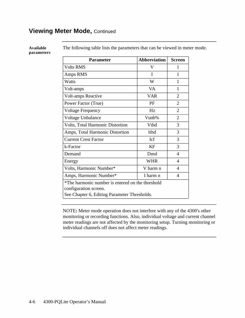
Available parameters
The following table lists the parameters that can be viewed in meter mode.
NOTE: Meter mode operation does not interfere with any of the 4300's other monitoring or recording functions. Also, individual voltage and current channel meter readings are not affected by the monitoring setup. Turning monitoring or individual channels off does not affect meter readings.
Parameter Abbreviation Screen
Volts RMS V 1
Amps RMS I 1
Watts W 1
Volt-amps VA 1
Volt-amps Reactive VAR 2
Power Factor (True) PF 2
Voltage Frequency Hz 2
Voltage Unbalance Vunb% 2
Volts, Total Harmonic Distortion Vthd 3
Amps, Total Harmonic Distortion Ithd 3
Current Crest Factor Icf 3
k-Factor KF 3
Demand Dmd 4
Energy WHR 4
Volts, Harmonic Number* V harm n 4
Amps, Harmonic Number* I harm n 4
*The harmonic number is entered on the threshold configuration screen. See Chapter 6, Editing Parameter Thresholds.
Scope and Meter Mode 4-7
Viewing Voltage and Current Phasors
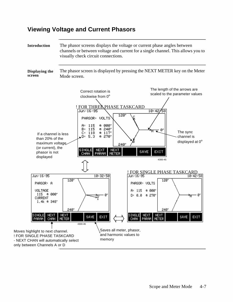
Introduction The phasor screens displays the voltage or current phase angles between channels or between voltage and current for a single channel. This allows you to visually check circuit connections.
Displaying the screen
The phasor screen is displayed by pressing the NEXT METER key on the Meter Mode screen.
The length of the arrows are scaled to the parameter values
If a channel is less than 20% of the maximum voltage (or current), the phasor is not displayed
Saves all meter, phasor, and harmonic values to memory
Correct rotation is clockwise from 0º
4300-45
4300-46
The sync channel is displayed at 0º
! FOR THREE PHASE TASKCARD
! FOR SINGLE PHASE TASKCARD
Moves highlight to next channel.! FOR SINGLE PHASE TASKCARD- NEXT CHAN will automatically select only between Channels A or D
4-8 4300-PQLite Operator’s Manual
Viewing Harmonics
Displaying the graph screen
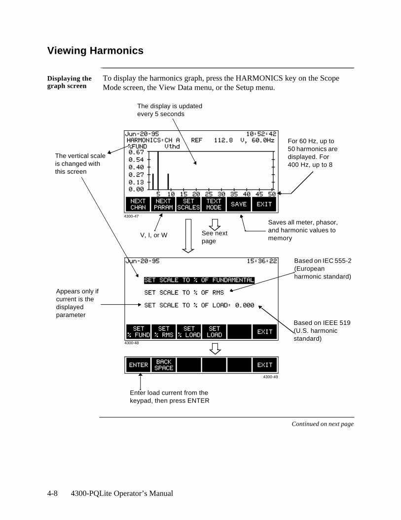
To display the harmonics graph, press the HARMONICS key on the Scope Mode screen, the View Data menu, or the Setup menu.
Continued on next page
The vertical scale is changed with this screen
For 60 Hz, up to 50 harmonics are displayed. For 400 Hz, up to 8
Saves all meter, phasor, and harmonic values to memory
The display is updated every 5 seconds
Enter load current from the keypad, then press ENTER
Appears only if current is the displayed parameter
Based on IEC 555-2 (European harmonic standard)
Based on IEEE 519 (U.S. harmonic standard)
See next page
4300-47
4300-48
4300-49
V, I, or W
Scope and Meter Mode 4-9
Viewing Harmonics, Continued
Viewing the text display
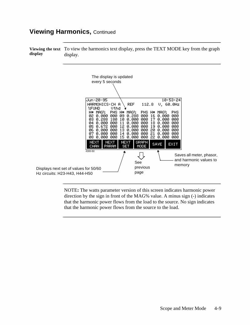
To view the harmonics text display, press the TEXT MODE key from the graph display.
NOTE: The watts parameter version of this screen indicates harmonic power direction by the sign in front of the MAG% value. A minus sign (-) indicates that the harmonic power flows from the load to the source. No sign indicates that the harmonic power flows from the source to the load.
The display is updated every 5 seconds
Saves all meter, phasor, and harmonic values to memory
See previous page
Displays next set of values for 50/60 Hz circuits: H23-H43, H44-H50
4300-50

4-10 4300-PQLite Operator’s Manual

Housekeeping Functions 5-1
Chapter 5
Housekeeping Functions
Overview
Introduction Housekeeping functions consists of the miscellaneous tasks that you need to perform to keep your 4300 running in an efficient and organized way. These are tasks that you might perform only occasionally.
NOTE No circuit connections need to be made for any of the procedures described in this chapter.
In this chapter The following topics are covered in this chapter.
Topic See Page
Entering a Site Name 5-2
Setting the Time and Date 5-4
Setting the LCD Light, Audible Alarm and Language 5-6
Clearing Memory 5-7
Resetting the 4300 to the Factory Configuration 5-8
Checking Site Status 5-11
Checking 4300 Status 5-12
Running a Self-Test 5-13
5-2 4300-PQLite Operator’s Manual
Entering a Site Name
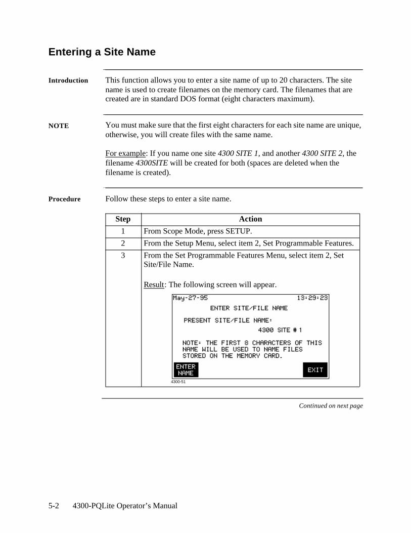
Introduction This function allows you to enter a site name of up to 20 characters. The site name is used to create filenames on the memory card. The filenames that are created are in standard DOS format (eight characters maximum).
NOTE You must make sure that the first eight characters for each site name are unique, otherwise, you will create files with the same name.
For example: If you name one site 4300 SITE 1, and another 4300 SITE 2, the filename 4300SITE will be created for both (spaces are deleted when the filename is created).
Procedure Follow these steps to enter a site name.
Continued on next page
Step Action
1 From Scope Mode, press SETUP.
2 From the Setup Menu, select item 2, Set Programmable Features.
3 From the Set Programmable Features Menu, select item 2, Set Site/File Name.
Result: The following screen will appear.
4300-51
Housekeeping Functions 5-3
Entering a Site Name, Continued
Procedure (continued) Step Action
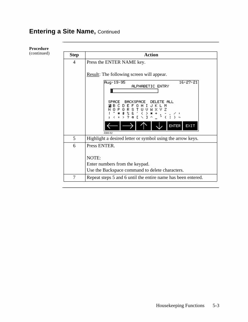
4 Press the ENTER NAME key.
Result: The following screen will appear.
5 Highlight a desired letter or symbol using the arrow keys.
6 Press ENTER.
NOTE:Enter numbers from the keypad.Use the Backspace command to delete characters.
7 Repeat steps 5 and 6 until the entire name has been entered.
4300-52
5-4 4300-PQLite Operator’s Manual
Setting the Time and Date
Displaying the screen
Follow these steps to display the time and date screen.
Setting the time Follow these steps to set the time.
Continued on next page
Step Action
1 Press SETUP from the Scope Mode screen.
2 Select item 2, Set Programmable Features, from the Setup Menu.
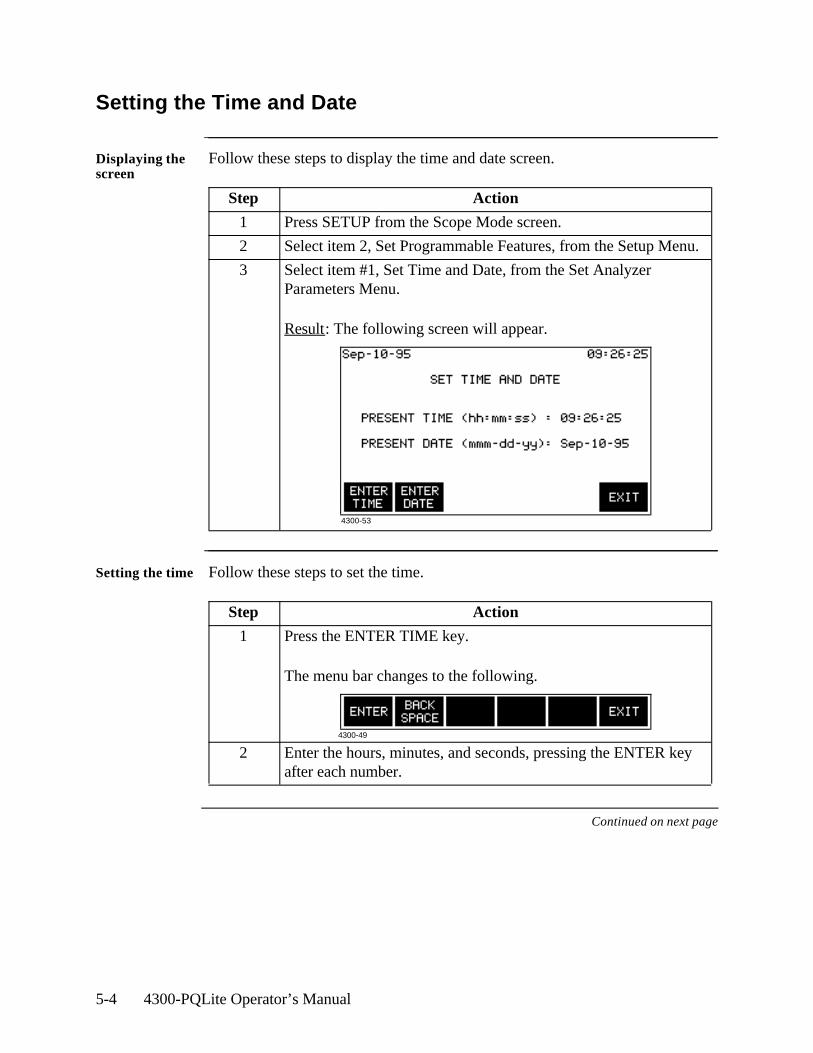
3 Select item #1, Set Time and Date, from the Set Analyzer Parameters Menu.
Result: The following screen will appear.
Step Action
1 Press the ENTER TIME key.
The menu bar changes to the following.
2 Enter the hours, minutes, and seconds, pressing the ENTER key after each number.
4300-53
4300-49
Housekeeping Functions 5-5
Setting the Time and Date, Continued
Setting the date Follow these steps to set the date.
Step Action
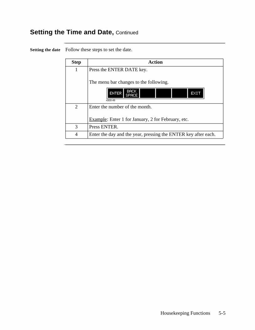
1 Press the ENTER DATE key.
The menu bar changes to the following.
2 Enter the number of the month.
Example: Enter 1 for January, 2 for February, etc.
3 Press ENTER.
4 Enter the day and the year, pressing the ENTER key after each.
4300-49

5-6 4300-PQLite Operator’s Manual
Setting the LCD Light, Audible Alarm and Language
Introduction The settings for the LCD backlight, audible alarm and language are controlled from the Set Programmable Features menu. Pressing the menu item number will change the setting for that function.
Displaying the screen
Follow these steps to display the Set Analyzer Parameters menu.
LCD backlight auto-shutoff
Enabled: The backlight for the LCD display will shut off if no key has been pressed for 15 minutes.
Disabled: The backlight for the LCD display will stay on continuously.
NOTE: The auto-shutoff feature extends the life of the battery and is recommended for use.
Audible alarm When set to ON the unit will beep for each event or error condition.
Select Language Display screens are programmed to appear in English language by default. However, with TASKCard PQLite V4.0 or higher, users may navigate through the menu screens in any of the following languages: French, Spanish, German, Italian. See page 1-2 for the procedures on how to select a new language.
Step Action
1 From the Scope Mode screen, press SETUP.
2 From the Setup Menu, select item 2, Set Programmable Features.Result: The following screen will appear.
Available in TASKCard V4.0 or higher
4300B-101
Housekeeping Functions 5-7
Clearing Memory
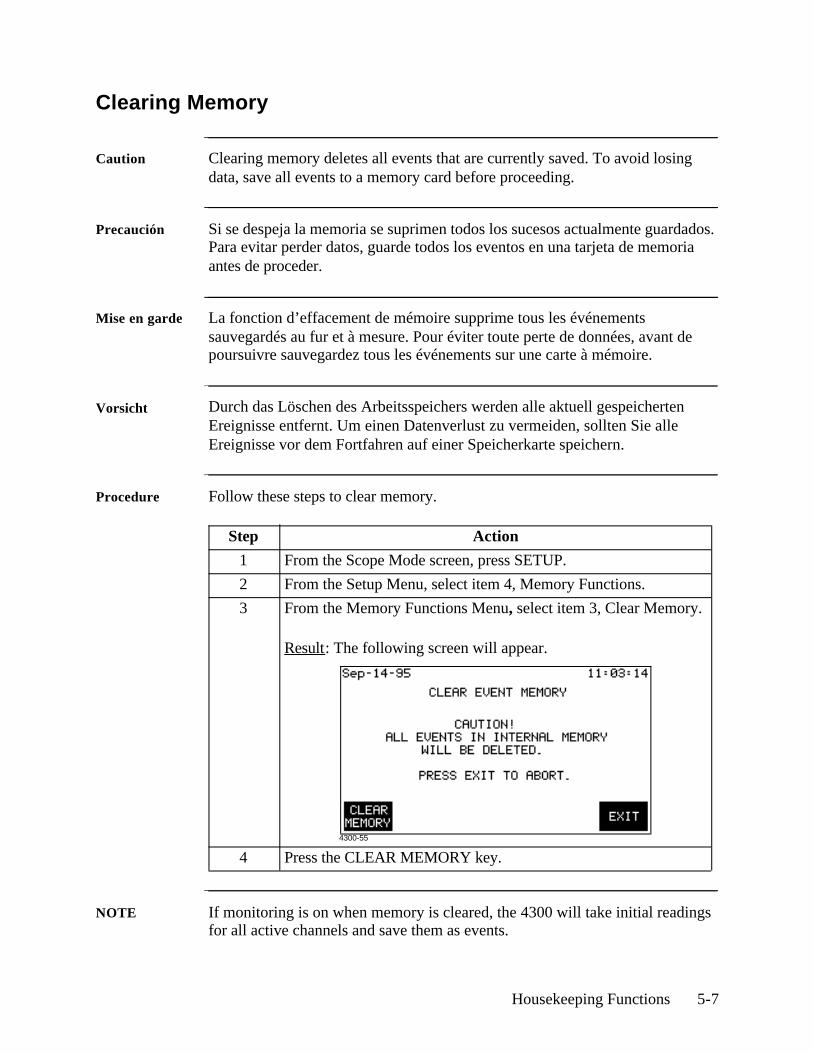
Caution Clearing memory deletes all events that are currently saved. To avoid losing data, save all events to a memory card before proceeding.
Precaución Si se despeja la memoria se suprimen todos los sucesos actualmente guardados. Para evitar perder datos, guarde todos los eventos en una tarjeta de memoria antes de proceder.
Mise en garde La fonction d’effacement de mémoire supprime tous les événements sauvegardés au fur et à mesure. Pour éviter toute perte de données, avant de poursuivre sauvegardez tous les événements sur une carte à mémoire.
Vorsicht Durch das Löschen des Arbeitsspeichers werden alle aktuell gespeicherten Ereignisse entfernt. Um einen Datenverlust zu vermeiden, sollten Sie alle Ereignisse vor dem Fortfahren auf einer Speicherkarte speichern.
Procedure Follow these steps to clear memory.
NOTE If monitoring is on when memory is cleared, the 4300 will take initial readings for all active channels and save them as events.
Step Action
1 From the Scope Mode screen, press SETUP.
2 From the Setup Menu, select item 4, Memory Functions.
3 From the Memory Functions Menu, select item 3, Clear Memory.
Result: The following screen will appear.
4 Press the CLEAR MEMORY key.4300-55
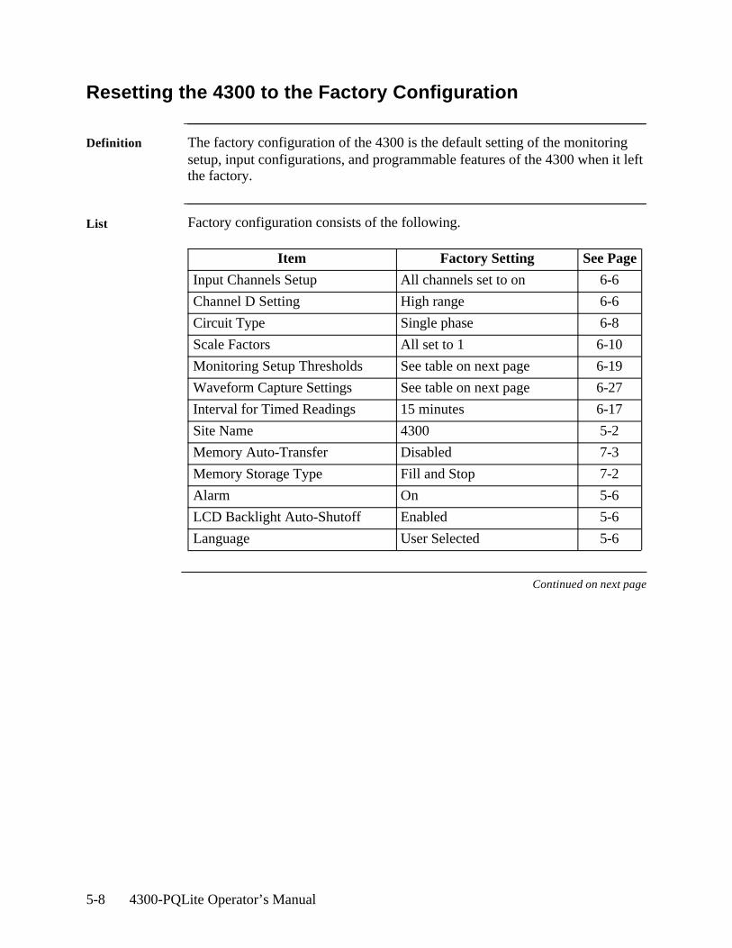
5-8 4300-PQLite Operator’s Manual
Resetting the 4300 to the Factory Configuration
Definition The factory configuration of the 4300 is the default setting of the monitoring setup, input configurations, and programmable features of the 4300 when it left the factory.
List Factory configuration consists of the following.
Continued on next page
Item Factory Setting See Page
Input Channels Setup All channels set to on 6-6
Channel D Setting High range 6-6
Circuit Type Single phase 6-8
Scale Factors All set to 1 6-10
Monitoring Setup Thresholds See table on next page 6-19
Waveform Capture Settings See table on next page 6-27
Interval for Timed Readings 15 minutes 6-17
Site Name 4300 5-2
Memory Auto-Transfer Disabled 7-3
Memory Storage Type Fill and Stop 7-2
Alarm On 5-6
LCD Backlight Auto-Shutoff Enabled 5-6
Language User Selected 5-6
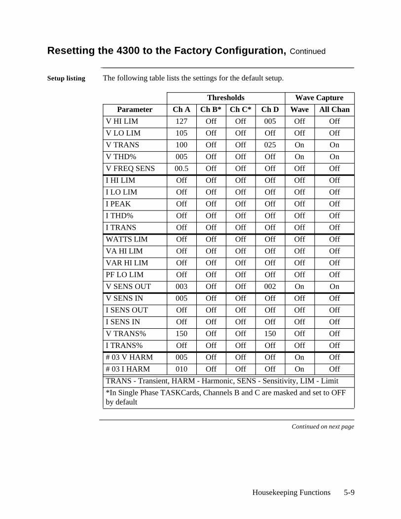
Housekeeping Functions 5-9
Resetting the 4300 to the Factory Configuration, Continued
Setup listing The following table lists the settings for the default setup.
Continued on next page
Thresholds Wave Capture
Parameter Ch A Ch B* Ch C* Ch D Wave All Chan
V HI LIM 127 Off Off 005 Off Off
V LO LIM 105 Off Off Off Off Off
V TRANS 100 Off Off 025 On On
V THD% 005 Off Off Off On On
V FREQ SENS 00.5 Off Off Off Off Off
I HI LIM Off Off Off Off Off Off
I LO LIM Off Off Off Off Off Off
I PEAK Off Off Off Off Off Off
I THD% Off Off Off Off Off Off
I TRANS Off Off Off Off Off Off
WATTS LIM Off Off Off Off Off Off
VA HI LIM Off Off Off Off Off Off
VAR HI LIM Off Off Off Off Off Off
PF LO LIM Off Off Off Off Off Off
V SENS OUT 003 Off Off 002 On On
V SENS IN 005 Off Off Off Off Off
I SENS OUT Off Off Off Off Off Off
I SENS IN Off Off Off Off Off Off
V TRANS% 150 Off Off 150 Off Off
I TRANS% Off Off Off Off Off Off
# 03 V HARM 005 Off Off Off On Off
# 03 I HARM 010 Off Off Off On Off
TRANS - Transient, HARM - Harmonic, SENS - Sensitivity, LIM - Limit
*In Single Phase TASKCards, Channels B and C are masked and set to OFF by default
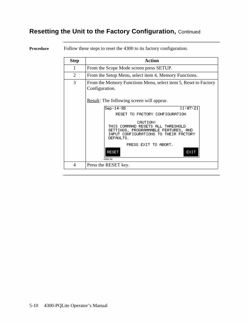
5-10 4300-PQLite Operator’s Manual
Resetting the Unit to the Factory Configuration, Continued
Procedure Follow these steps to reset the 4300 to its factory configuration.
Step Action
1 From the Scope Mode screen press SETUP.
2 From the Setup Menu, select item 4, Memory Functions.
3 From the Memory Functions Menu, select item 5, Reset to Factory Configuration.
Result: The following screen will appear.
4 Press the RESET key.4300-56
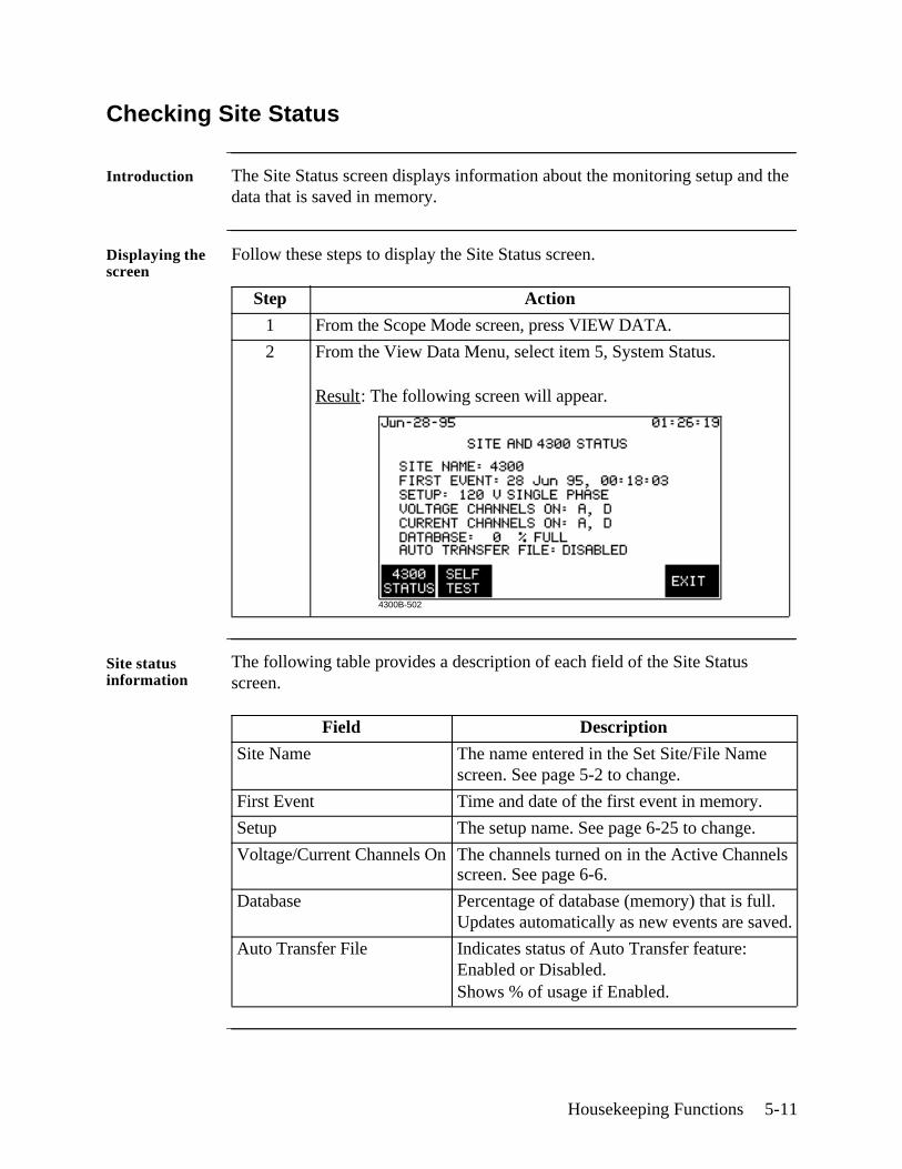
Housekeeping Functions 5-11
Checking Site Status
Introduction The Site Status screen displays information about the monitoring setup and the data that is saved in memory.
Displaying the screen
Follow these steps to display the Site Status screen.
Site status information
The following table provides a description of each field of the Site Status screen.
Step Action
1 From the Scope Mode screen, press VIEW DATA.
2 From the View Data Menu, select item 5, System Status.
Result: The following screen will appear.
Field Description
Site Name The name entered in the Set Site/File Name screen. See page 5-2 to change.
First Event Time and date of the first event in memory.
Setup The setup name. See page 6-25 to change.
Voltage/Current Channels On The channels turned on in the Active Channels screen. See page 6-6.
Database Percentage of database (memory) that is full. Updates automatically as new events are saved.
Auto Transfer File Indicates status of Auto Transfer feature: Enabled or Disabled. Shows % of usage if Enabled.
4300B-502
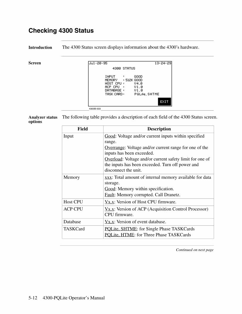
5-12 4300-PQLite Operator’s Manual
Checking 4300 Status
Introduction The 4300 Status screen displays information about the 4300’s hardware.
Screen
Analyzer status options
The following table provides a description of each field of the 4300 Status screen.
Continued on next page
Field Description
Input Good: Voltage and/or current inputs within specified range.Overrange: Voltage and/or current range for one of the inputs has been exceeded.Overload: Voltage and/or current safety limit for one of the inputs has been exceeded. Turn off power and disconnect the unit.
Memory xxx: Total amount of internal memory available for data storage.Good: Memory within specification.Fault: Memory corrupted. Call Dranetz.
Host CPU Vx.x: Version of Host CPU firmware.
ACP CPU Vx.x: Version of ACP (Acquisition Control Processor) CPU firmware.
Database Vx.x: Version of event database.
TASKCard PQLite, SHTME: for Single Phase TASKCardsPQLite, HTME: for Three Phase TASKCards
4300B-503
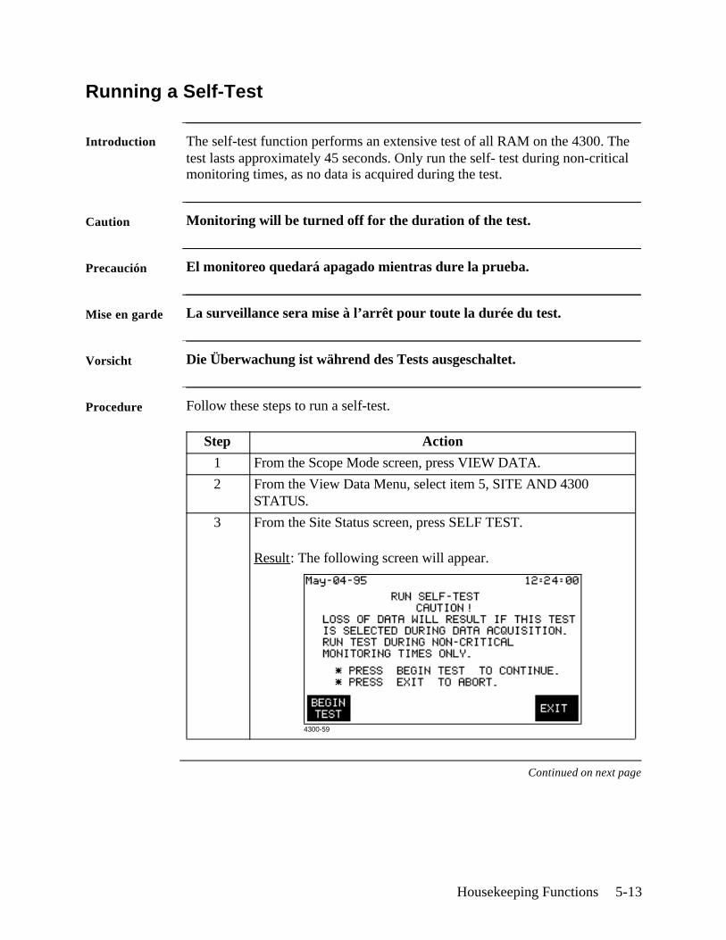
Housekeeping Functions 5-13
Running a Self-Test
Introduction The self-test function performs an extensive test of all RAM on the 4300. The test lasts approximately 45 seconds. Only run the self- test during non-critical monitoring times, as no data is acquired during the test.
Caution Monitoring will be turned off for the duration of the test.
Precaución El monitoreo quedará apagado mientras dure la prueba.
Mise en garde La surveillance sera mise à l’arrêt pour toute la durée du test.
Vorsicht Die Überwachung ist während des Tests ausgeschaltet.
Procedure Follow these steps to run a self-test.
Continued on next page
Step Action
1 From the Scope Mode screen, press VIEW DATA.
2 From the View Data Menu, select item 5, SITE AND 4300 STATUS.
3 From the Site Status screen, press SELF TEST.
Result: The following screen will appear.
4300-59

5-14 4300-PQLite Operator’s Manual
Running a Self-Test, Continued
Procedure (continued)
When test is complete
At the completion of the test, the Site Status screen is displayed. See page5-11.
Step Action
4 Press BEGIN TEST.
Result: The following screen is displayed for the duration of the test.
4300-60
Long-term Monitoring 6-1
Chapter 6
Long-term Monitoring
Overview
When to monitor?
This chapter contains information about how to set up the 4300 for long-term monitoring of an electrical system. You generally monitor a circuit in situations where scope or meter measurements don’t give you the data that you need to diagnose a problem. The length of time you monitor a circuit can vary from a few hours to a few weeks depending on your application.
Definitions Event: Any data that the 4300 saves to memory; usually based on exceeding a threshold.
Parameter threshold: A user entered value that the 4300 compares to a measurement to decide if an event occurs. Also called a limit. For example, if the input voltage is measured as 135 Vrms, and the parameter threshold for voltage is 132 Vrms, the 4300 saves this limit crossing to memory as an event.
Waveform capture: A function that saves the actual voltage and/or current waveforms that occurred at the time of an event.
Setup: A preset condition of parameter thresholds and waveform capture settings for each channel that determines what will constitute an event and what waveform data will be saved when this event occurs.
Setup methods There are two methods you can use to setup the 4300: Easy Start or Advanced. Easy Start prompts you for information and then sets up the unit automatically. With the advanced method you have total control over all setup functions.
Choosing a setup method
The setup method you choose will depend on your application and your familiarity with the operation of the 4300. The differences between the Easy Start and Advanced methods are discussed below.
Continued on next page
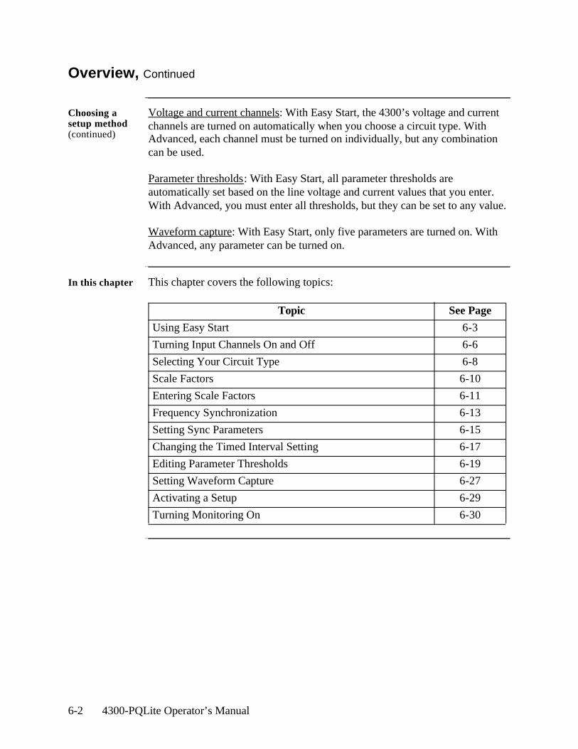
6-2 4300-PQLite Operator’s Manual
Overview, Continued
Choosing a setup method (continued)
Voltage and current channels: With Easy Start, the 4300’s voltage and current channels are turned on automatically when you choose a circuit type. With Advanced, each channel must be turned on individually, but any combination can be used.
Parameter thresholds: With Easy Start, all parameter thresholds are automatically set based on the line voltage and current values that you enter. With Advanced, you must enter all thresholds, but they can be set to any value.
Waveform capture: With Easy Start, only five parameters are turned on. With Advanced, any parameter can be turned on.
In this chapter This chapter covers the following topics:
Topic See Page
Using Easy Start 6-3
Turning Input Channels On and Off 6-6
Selecting Your Circuit Type 6-8
Scale Factors 6-10
Entering Scale Factors 6-11
Frequency Synchronization 6-13
Setting Sync Parameters 6-15
Changing the Timed Interval Setting 6-17
Editing Parameter Thresholds 6-19
Setting Waveform Capture 6-27
Activating a Setup 6-29
Turning Monitoring On 6-30
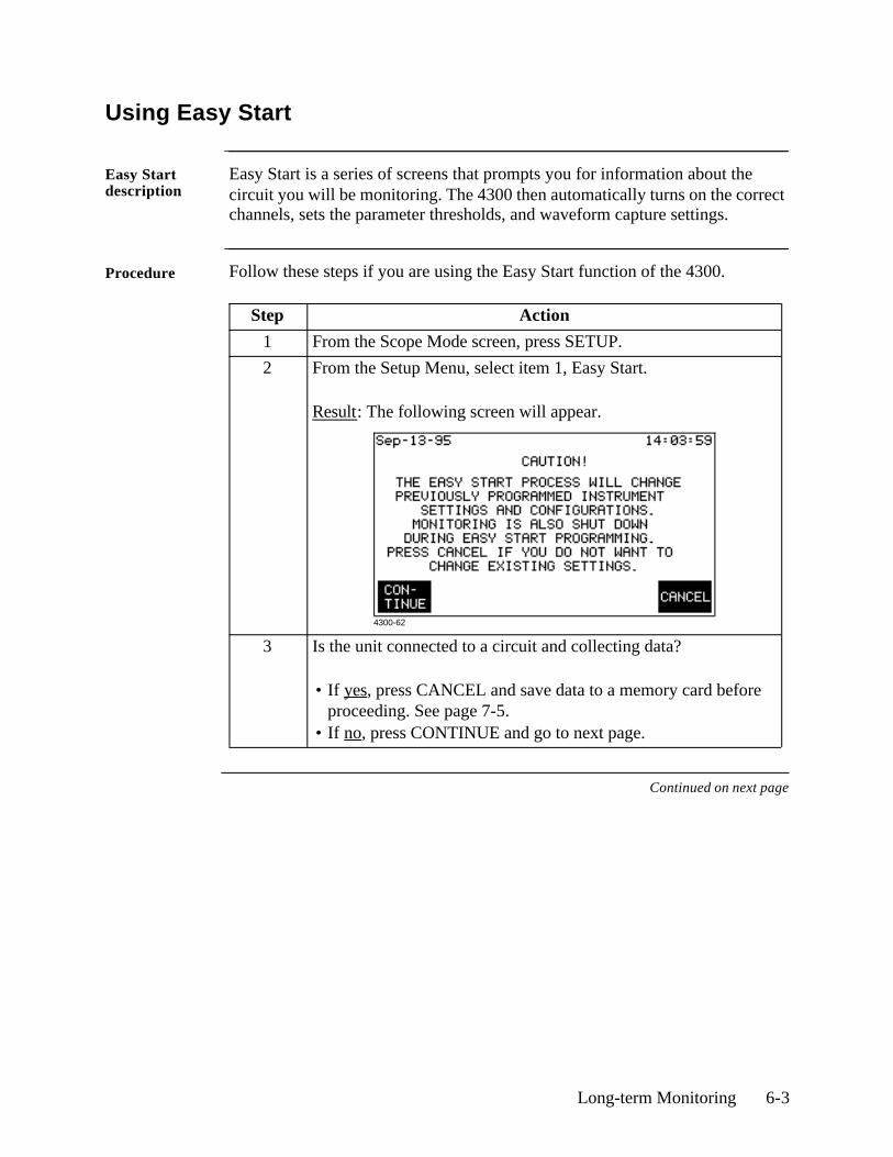
Long-term Monitoring 6-3
Using Easy Start
Easy Start description
Easy Start is a series of screens that prompts you for information about the circuit you will be monitoring. The 4300 then automatically turns on the correct channels, sets the parameter thresholds, and waveform capture settings.
Procedure Follow these steps if you are using the Easy Start function of the 4300.
Continued on next page
Step Action
1 From the Scope Mode screen, press SETUP.
2 From the Setup Menu, select item 1, Easy Start.
Result: The following screen will appear.
3 Is the unit connected to a circuit and collecting data?
• If yes, press CANCEL and save data to a memory card before proceeding. See page 7-5.
• If no, press CONTINUE and go to next page.
4300-62
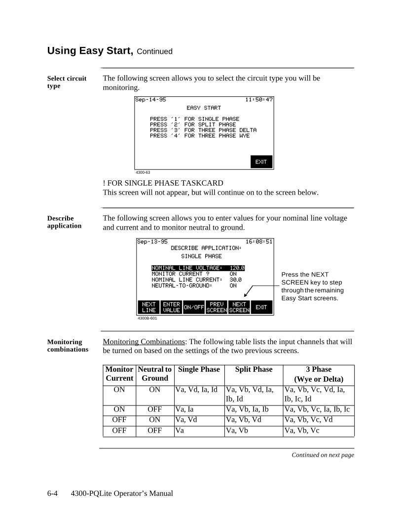
6-4 4300-PQLite Operator’s Manual
Using Easy Start, Continued
Select circuit type
The following screen allows you to select the circuit type you will be monitoring.
! FOR SINGLE PHASE TASKCARDThis screen will not appear, but will continue on to the screen below.
Describe application
The following screen allows you to enter values for your nominal line voltage and current and to monitor neutral to ground.
Monitoring combinations
Monitoring Combinations: The following table lists the input channels that will be turned on based on the settings of the two previous screens.
Continued on next page
Monitor Current
Neutral to Ground
Single Phase Split Phase 3 Phase(Wye or Delta)
ON ON Va, Vd, Ia, Id Va, Vb, Vd, Ia, Ib, Id
Va, Vb, Vc, Vd, Ia, Ib, Ic, Id
ON OFF Va, Ia Va, Vb, Ia, Ib Va, Vb, Vc, Ia, Ib, IcOFF ON Va, Vd Va, Vb, Vd Va, Vb, Vc, VdOFF OFF Va Va, Vb Va, Vb, Vc
4300B-601
Press the NEXT SCREEN key to step through the remaining Easy Start screens.
4300-63
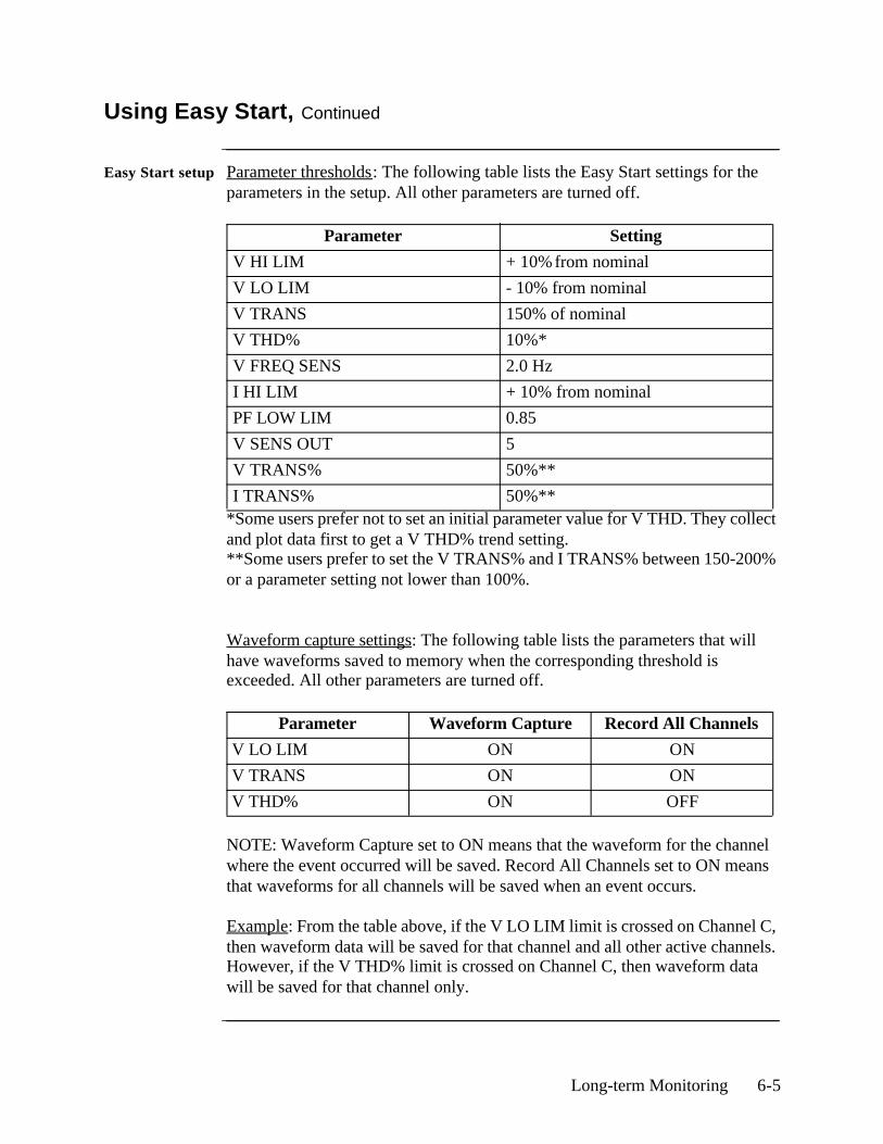
Long-term Monitoring 6-5
Using Easy Start, Continued
Easy Start setup Parameter thresholds: The following table lists the Easy Start settings for the parameters in the setup. All other parameters are turned off.
*Some users prefer not to set an initial parameter value for V THD. They collect and plot data first to get a V THD% trend setting.**Some users prefer to set the V TRANS% and I TRANS% between 150-200% or a parameter setting not lower than 100%.
Waveform capture settings: The following table lists the parameters that will have waveforms saved to memory when the corresponding threshold is exceeded. All other parameters are turned off.
NOTE: Waveform Capture set to ON means that the waveform for the channel where the event occurred will be saved. Record All Channels set to ON means that waveforms for all channels will be saved when an event occurs.
Example: From the table above, if the V LO LIM limit is crossed on Channel C, then waveform data will be saved for that channel and all other active channels. However, if the V THD% limit is crossed on Channel C, then waveform data will be saved for that channel only.
Parameter Setting
V HI LIM + 10% from nominal
V LO LIM - 10% from nominal
V TRANS 150% of nominal
V THD% 10%*
V FREQ SENS 2.0 Hz
I HI LIM + 10% from nominal
PF LOW LIM 0.85
V SENS OUT 5
V TRANS% 50%**
I TRANS% 50%**
Parameter Waveform Capture Record All Channels
V LO LIM ON ON
V TRANS ON ON
V THD% ON OFF
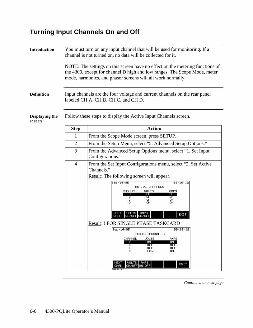
6-6 4300-PQLite Operator’s Manual
Turning Input Channels On and Off
Introduction You must turn on any input channel that will be used for monitoring. If a channel is not turned on, no data will be collected for it.
NOTE: The settings on this screen have no effect on the metering functions of the 4300, except for channel D high and low ranges. The Scope Mode, meter mode, harmonics, and phasor screens will all work normally.
Definition Input channels are the four voltage and current channels on the rear panel labeled CH A, CH B, CH C, and CH D.
Displaying the screen
Follow these steps to display the Active Input Channels screen.
Continued on next page
Step Action
1 From the Scope Mode screen, press SETUP.
2 From the Setup Menu, select “5. Advanced Setup Options.”
3 From the Advanced Setup Options menu, select “1. Set Input Configurations.”
4 From the Set Input Configurations menu, select “2. Set Active Channels.”Result: The following screen will appear.
Result: ! FOR SINGLE PHASE TASKCARD
4300B-602
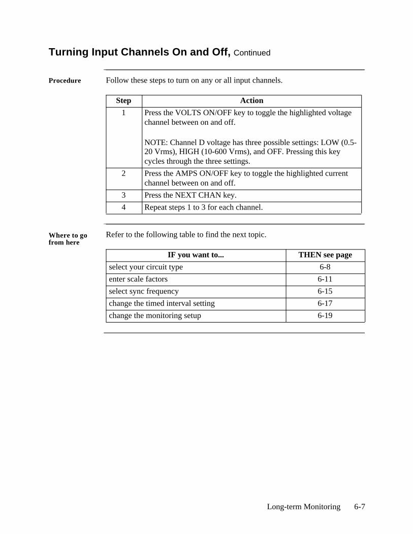
Long-term Monitoring 6-7
Turning Input Channels On and Off, Continued
Procedure Follow these steps to turn on any or all input channels.
Where to go from here
Refer to the following table to find the next topic.
Step Action
1 Press the VOLTS ON/OFF key to toggle the highlighted voltage channel between on and off.
NOTE: Channel D voltage has three possible settings: LOW (0.5-20 Vrms), HIGH (10-600 Vrms), and OFF. Pressing this key cycles through the three settings.
2 Press the AMPS ON/OFF key to toggle the highlighted current channel between on and off.
3 Press the NEXT CHAN key.
4 Repeat steps 1 to 3 for each channel.
IF you want to... THEN see page
select your circuit type 6-8
enter scale factors 6-11
select sync frequency 6-15
change the timed interval setting 6-17
change the monitoring setup 6-19
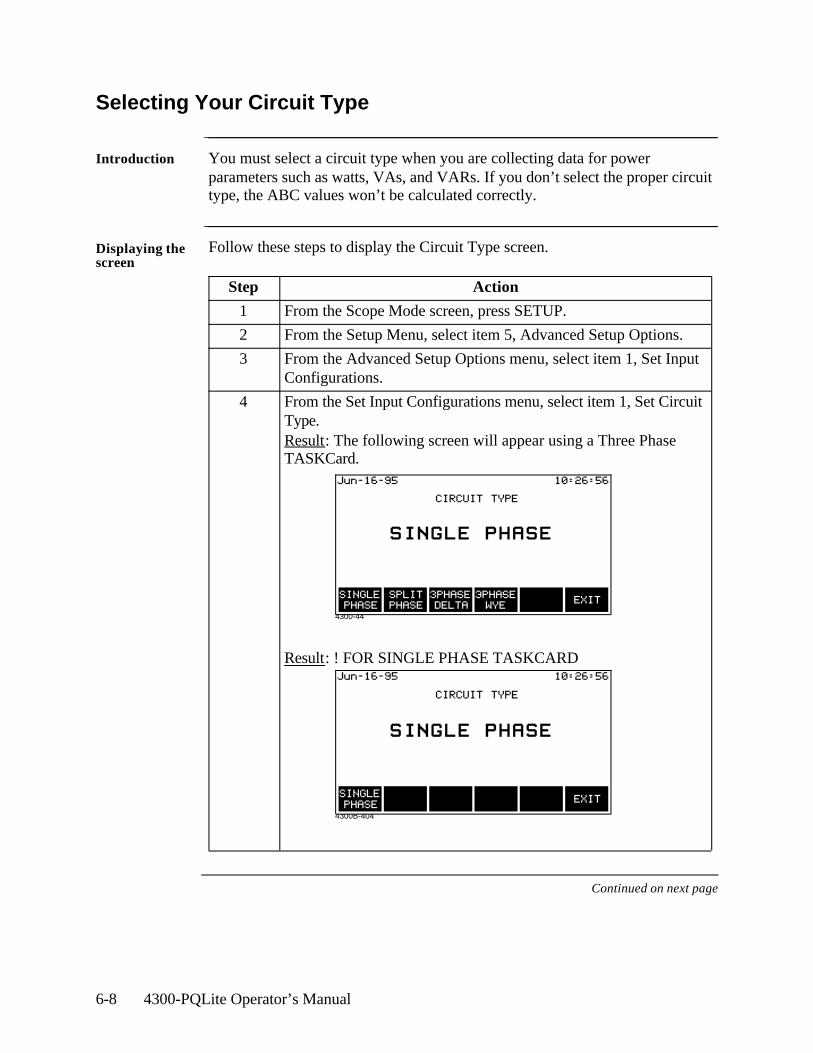
6-8 4300-PQLite Operator’s Manual
4300B-404
Selecting Your Circuit Type
Introduction You must select a circuit type when you are collecting data for power parameters such as watts, VAs, and VARs. If you don’t select the proper circuit type, the ABC values won’t be calculated correctly.
Displaying the screen
Follow these steps to display the Circuit Type screen.
Continued on next page
Step Action
1 From the Scope Mode screen, press SETUP.
2 From the Setup Menu, select item 5, Advanced Setup Options.
3 From the Advanced Setup Options menu, select item 1, Set Input Configurations.
4 From the Set Input Configurations menu, select item 1, Set Circuit Type.Result: The following screen will appear using a Three Phase TASKCard.
Result: ! FOR SINGLE PHASE TASKCARD
4300-44
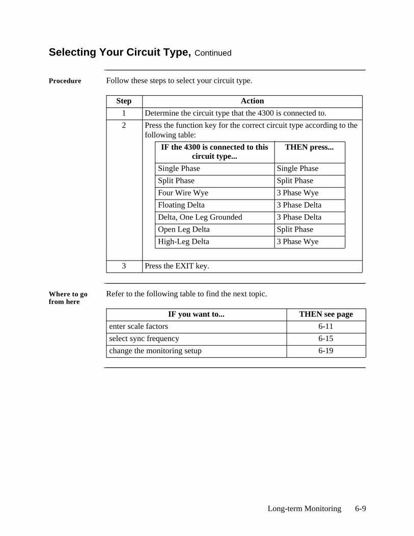
Long-term Monitoring 6-9
Selecting Your Circuit Type, Continued
Procedure Follow these steps to select your circuit type.
Where to go from here
Refer to the following table to find the next topic.
Step Action
1 Determine the circuit type that the 4300 is connected to.
2 Press the function key for the correct circuit type according to the following table:
IF the 4300 is connected to this circuit type...
THEN press...
Single Phase Single Phase
Split Phase Split Phase
Four Wire Wye 3 Phase Wye
Floating Delta 3 Phase Delta
Delta, One Leg Grounded 3 Phase Delta
Open Leg Delta Split Phase
High-Leg Delta 3 Phase Wye
3 Press the EXIT key.
IF you want to... THEN see page
enter scale factors 6-11
select sync frequency 6-15
change the monitoring setup 6-19
6-10 4300-PQLite Operator’s Manual
Scale Factors
What is a scale factor?
A scale factor is the ratio of the input to output parameter for a particular current transformer (CT) or potential transformer (PT). A scale factor is entered into the 4300 and then multiplied automatically by the measured voltage and current so that the unit displays the correct values.
NOTE: If voltage and current connections are made without using any of the above named devices, the scale factor should be set to 1.
When to use Scale factors must be entered for the following conditions:• A Dranetz current probe is connected to a permanently installed CT.• The current connections are made using a Dranetz ISO box.• The voltage connections are made using a PT.
Dranetz equipment
When a Dranetz current probe or isolation transformer (model ISO-658-5) is chosen from the Current Probe Selection screen (see page 3-17), the correct scale factor is set automatically and does not have to be entered manually.
NOTE: The ISO-658-5 is typically used when connecting to the secondary of an existing current transformer. The scale factor of the existing transformer must be entered in order for the 4300 to make the correct calculation.
Non-Dranetz equipment
Refer to the CT name plate or to the manufacturer’s literature to determine the scale factor.
Example calculation
The scale factor for a single CT or PT is calculated from its step-up or step-down ratio.
If a current transformer has a step-down ratio of 1000A:5A, therefore:Scale Factor = 1000/5 = 200
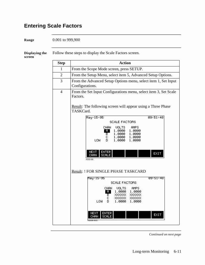
Long-term Monitoring 6-11
Entering Scale Factors
Range 0.001 to 999,900
Displaying the screen
Follow these steps to display the Scale Factors screen.
Continued on next page
Step Action
1 From the Scope Mode screen, press SETUP.
2 From the Setup Menu, select item 5, Advanced Setup Options.
3 From the Advanced Setup Options menu, select item 1, Set Input Configurations.
4 From the Set Input Configurations menu, select item 3, Set Scale Factors.
Result: The following screen will appear using a Three Phase TASKCard.
Result: ! FOR SINGLE PHASE TASKCARD
4300-66
4300B-603
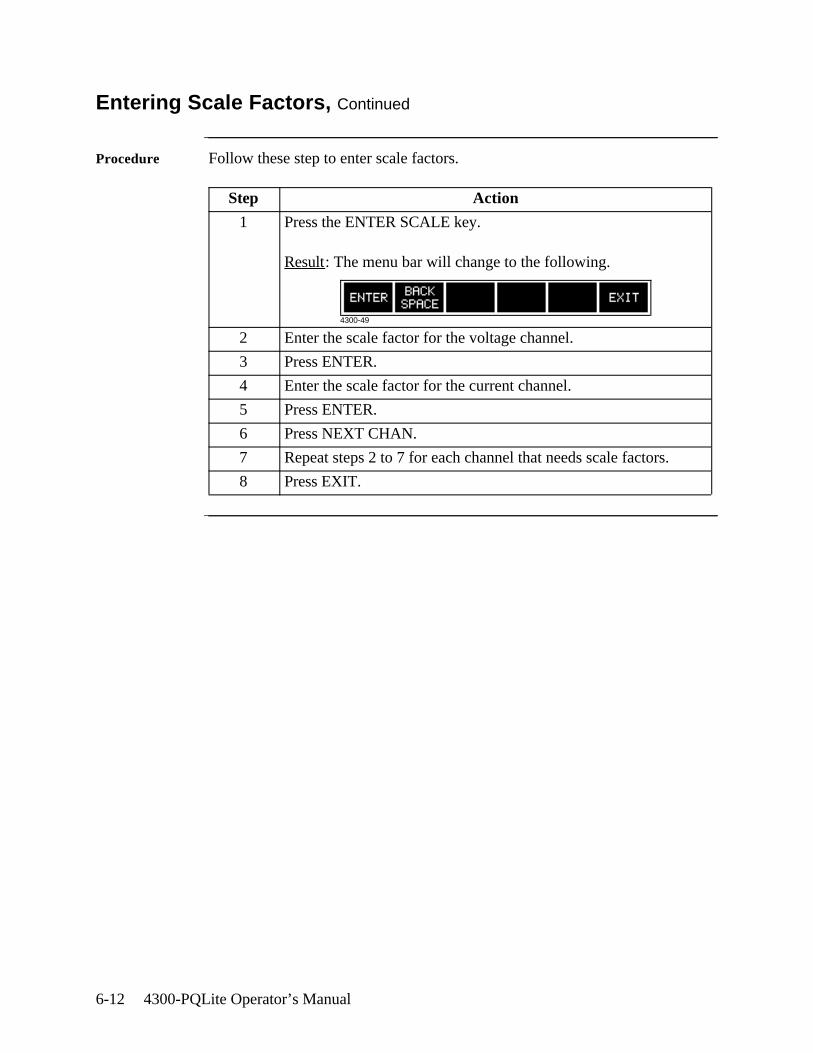
6-12 4300-PQLite Operator’s Manual
Entering Scale Factors, Continued
Procedure Follow these step to enter scale factors.
Step Action
1 Press the ENTER SCALE key.
Result: The menu bar will change to the following.
2 Enter the scale factor for the voltage channel.
3 Press ENTER.
4 Enter the scale factor for the current channel.
5 Press ENTER.
6 Press NEXT CHAN.
7 Repeat steps 2 to 7 for each channel that needs scale factors.
8 Press EXIT.
4300-49
Long-term Monitoring 6-13
Frequency Synchronization
Introduction Normal frequency synchronization (sync) of 4300 analog signal processing circuits is controlled by sampling the external ac signal input on channel A. Loss of external sync causes the 4300 to poll other valid voltage channels (A, B, or C) for an alternate external sync. If none exists, then internal sync is automatically selected.
Depending on the type of circuit configuration, the instrument will attempt to autosearch to sync to any valid voltage channel (see table below). Users may choose to disable the autosearch function and specify sync mode EXT CH D. Typically, external sync on CH D is specified if it is known that the signals on A, B or C are inappropriate for use as a sync source (i.e. the frequency is unstable or DC). A clean 50, 60 or 400 Hz signal can be input to CH D and used as a sync signal.
Failure to connect an external sync or to select an internal sync during current monitoring will result in erroneous data being collected and displayed.
Sync during power-up
On power-up, the 4300 will initially attempt to sync on the channel A input voltage signal. If a valid input is available, then the 4300 will sync in the external mode and will remain in this mode until the sync level is lost.
If channel A sync cannot be acquired, then the next valid voltage channel will be polled to re-initiate external sync in accordance with the following table.
Loss of external sync during power up
If external sync cannot be acquired on any valid channel, then the 4300 will revert to internal sync. The frequency used for internal is entered on the Sync Parameters screen. Refer to page 6-15 for the procedure.
The valid voltage channels will be polled in the background in an attempt to reacquire external sync.
When no external sync signal is found, an error message is displayed to inform you of this condition. The loss of sync is also sent to event memory for future recall.
Circuit Type Valid Voltage Channels for Sync
Single Phase A, D
Split Phase A, B, D
3 Phase Delta A, B, C, D
3 Phase Wye A, B, C, D
6-14 4300-PQLite Operator’s Manual
Frequency Synchronization, continued
Loss of sync during monitoring
If sync is lost during monitoring of out of limit events, the 4300 will attempt to reacquire sync on the present sync channel for one minute. If after one minute sync cannot be reacquired, the other valid channels will be attempted without any delay. If sync cannot be acquired on these channels, then the 4300 will switch to internal sync.
The internal sync in this condition will be the last frequency measured before sync was lost. The internal sync frequency entered in the Sync Parameters screen (see next page) will be used if you change to internal sync or if a valid sync was never acquired.
The one minute time-out simulates a long duration interruption which, in turn, generates a TIMEOUT event that normally permits the 4300 to attempt to sync to another valid channel.
NOTE Parameters such as energy, harmonics, and other steady state metering data are measured more accurately using averaging. Averaging helps to eliminate the uninteresting and misleading effects of short-term changes. All signals including stable signals can be subject to the effects of noise. Averaging helps to increase the signal to noise ratio in the measurement of stable signals. To fill this requirement, Timed events, Energy parameters and Meter data are constructed from composite cycle data. A composite cycle is a single representative cycle made from the super-imposed average of 64 measurement cycles. At 50/60 Hz, one measurement cycle is one power frequency cycle. At 400 Hz, one measurement cycle is eight cycles. One measurement cycle consists of 128 samples at 50/60 Hz. At 400 Hz, there are 16 samples per power frequency cycle and eight cycles per measurement cycle. A composite is constructed from 64 contiguous measurement cycles.
FAILURE TO SECURE A STABLE SYNCHRONIZATION TO THE MEASUREMENT SIGNAL WILL SERIOUSLY DEGRADE THE ACCURACY OF TIMED EVENTS, ENERGY PARAMETERS AND METER DATA.
In general, if the unit is searching for a sync frequency, the composite meter data will appear lower than the single cycle event or single cycle scope data. For instance, this can occur at generator sites where the frequency stability can vary relative to loading.
Long-term Monitoring 6-15
Setting Sync Parameters
Introduction The sync parameters consist of the Sync Mode and the Nominal Frequency.
Sync mode Default: EXTERNAL
External: When set to EXTERNAL, the 4300 attempts to sync to an incoming voltage signal as described on the previous two pages.
Internal: When set to INTERNAL, the 4300 uses the nominal frequency when making measurements.
External Channel D: When set to EXT CH D, the 4300 only attempts to sync to Vd.
Nominal frequency
The nominal frequency is used when the sync mode is set to internal or if a valid external sync was never acquired.
Default: 60 Hz.
NOTE: You should enter a nominal frequency that matches your line frequency. This ensures that if the 4300 loses external sync, it will have a corresponding internal sync.
Displaying the screen
Follow these steps to display the Sync Parameters screen.
Continued on next page
Step Action
1 From the Scope Mode screen, press SETUP.
2 From the Setup Menu, select item 5, Advanced Setup Options.
3 From the Advanced Setup Options menu, select item 1, Set Input Configurations.
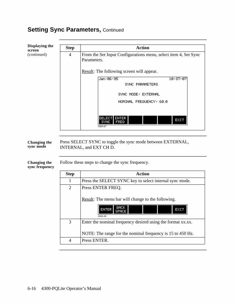
6-16 4300-PQLite Operator’s Manual
Setting Sync Parameters, Continued
Displaying the screen (continued)
Changing the sync mode
Press SELECT SYNC to toggle the sync mode between EXTERNAL, INTERNAL, and EXT CH D.
Changing the sync frequency
Follow these steps to change the sync frequency.
Step Action
4 From the Set Input Configurations menu, select item 4, Set Sync Parameters.
Result: The following screen will appear.
Step Action
1 Press the SELECT SYNC key to select internal sync mode.
2 Press ENTER FREQ.
Result: The menu bar will change to the following.
3 Enter the nominal frequency desired using the format xx.xx.
NOTE: The range for the nominal frequency is 15 to 450 Hz.
4 Press ENTER.
4300-67
4300-49
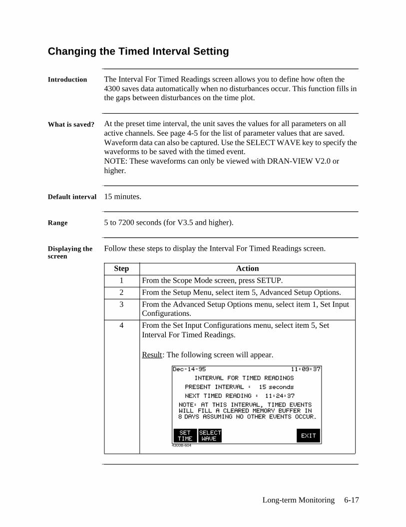
Long-term Monitoring 6-17
Changing the Timed Interval Setting
Introduction The Interval For Timed Readings screen allows you to define how often the 4300 saves data automatically when no disturbances occur. This function fills in the gaps between disturbances on the time plot.
What is saved? At the preset time interval, the unit saves the values for all parameters on all active channels. See page 4-5 for the list of parameter values that are saved. Waveform data can also be captured. Use the SELECT WAVE key to specify the waveforms to be saved with the timed event. NOTE: These waveforms can only be viewed with DRAN-VIEW V2.0 or higher.
Default interval 15 minutes.
Range 5 to 7200 seconds (for V3.5 and higher).
Displaying the screen
Follow these steps to display the Interval For Timed Readings screen.
Step Action
1 From the Scope Mode screen, press SETUP.
2 From the Setup Menu, select item 5, Advanced Setup Options.
3 From the Advanced Setup Options menu, select item 1, Set Input Configurations.
4 From the Set Input Configurations menu, select item 5, Set Interval For Timed Readings.
Result: The following screen will appear.
4300B-604
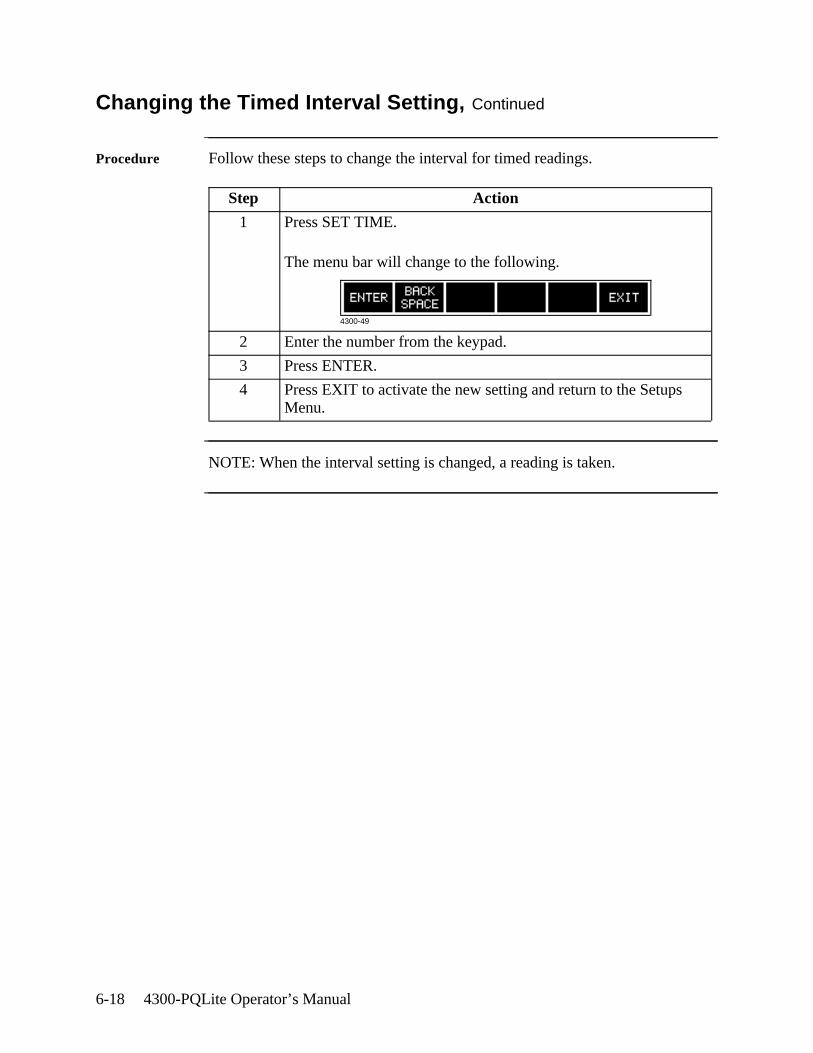
6-18 4300-PQLite Operator’s Manual
Changing the Timed Interval Setting, Continued
Procedure Follow these steps to change the interval for timed readings.
NOTE: When the interval setting is changed, a reading is taken.
Step Action
1 Press SET TIME.
The menu bar will change to the following.
2 Enter the number from the keypad.
3 Press ENTER.
4 Press EXIT to activate the new setting and return to the Setups Menu.
4300-49
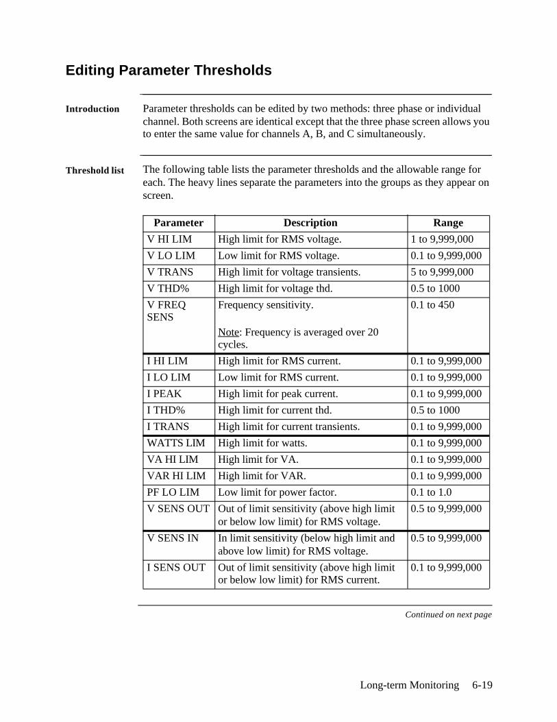
Long-term Monitoring 6-19
Editing Parameter Thresholds
Introduction Parameter thresholds can be edited by two methods: three phase or individual channel. Both screens are identical except that the three phase screen allows you to enter the same value for channels A, B, and C simultaneously.
Threshold list The following table lists the parameter thresholds and the allowable range for each. The heavy lines separate the parameters into the groups as they appear on screen.
Continued on next page
Parameter Description Range
V HI LIM High limit for RMS voltage. 1 to 9,999,000
V LO LIM Low limit for RMS voltage. 0.1 to 9,999,000
V TRANS High limit for voltage transients. 5 to 9,999,000
V THD% High limit for voltage thd. 0.5 to 1000
V FREQ SENS
Frequency sensitivity.
Note: Frequency is averaged over 20 cycles.
0.1 to 450
I HI LIM High limit for RMS current. 0.1 to 9,999,000
I LO LIM Low limit for RMS current. 0.1 to 9,999,000
I PEAK High limit for peak current. 0.1 to 9,999,000
I THD% High limit for current thd. 0.5 to 1000
I TRANS High limit for current transients. 0.1 to 9,999,000
WATTS LIM High limit for watts. 0.1 to 9,999,000
VA HI LIM High limit for VA. 0.1 to 9,999,000
VAR HI LIM High limit for VAR. 0.1 to 9,999,000
PF LO LIM Low limit for power factor. 0.1 to 1.0
V SENS OUT Out of limit sensitivity (above high limit or below low limit) for RMS voltage.
0.5 to 9,999,000
V SENS IN In limit sensitivity (below high limit and above low limit) for RMS voltage.
0.5 to 9,999,000
I SENS OUT Out of limit sensitivity (above high limit or below low limit) for RMS current.
0.1 to 9,999,000
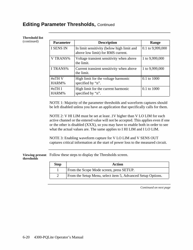
6-20 4300-PQLite Operator’s Manual
Editing Parameter Thresholds, Continued
Threshold list (continued)
NOTE 1: Majority of the parameter thresholds and waveform captures should be left disabled unless you have an application that specifically calls for them.
NOTE 2: V HI LIM must be set at least .1V higher than V LO LIM for each active channel or the entered value will not be accepted. This applies even if one or the other is disabled (XXX), so you may have to enable both in order to see what the actual values are. The same applies to I HI LIM and I LO LIM.
NOTE 3: Enabling waveform capture for V LO LIM and V SENS OUT captures critical information at the start of power loss to the measured circuit.
Viewing present thresholds
Follow these steps to display the Thresholds screen.
Continued on next page
Parameter Description Range
I SENS IN In limit sensitivity (below high limit and above low limit) for RMS current.
0.1 to 9,999,000
V TRANS% Voltage transient sensitivity when above the limit.
1 to 9,999,000
I TRANS% Current transient sensitivity when above the limit.
1 to 9,999,000
#nTH V HARM%
High limit for the voltage harmonic specified by “n”.
0.1 to 1000
#nTH I HARM%
High limit for the current harmonic specified by “n”.
0.1 to 1000
Step Action
1 From the Scope Mode screen, press SETUP.
2 From the Setup Menu, select item 5, Advanced Setup Options.
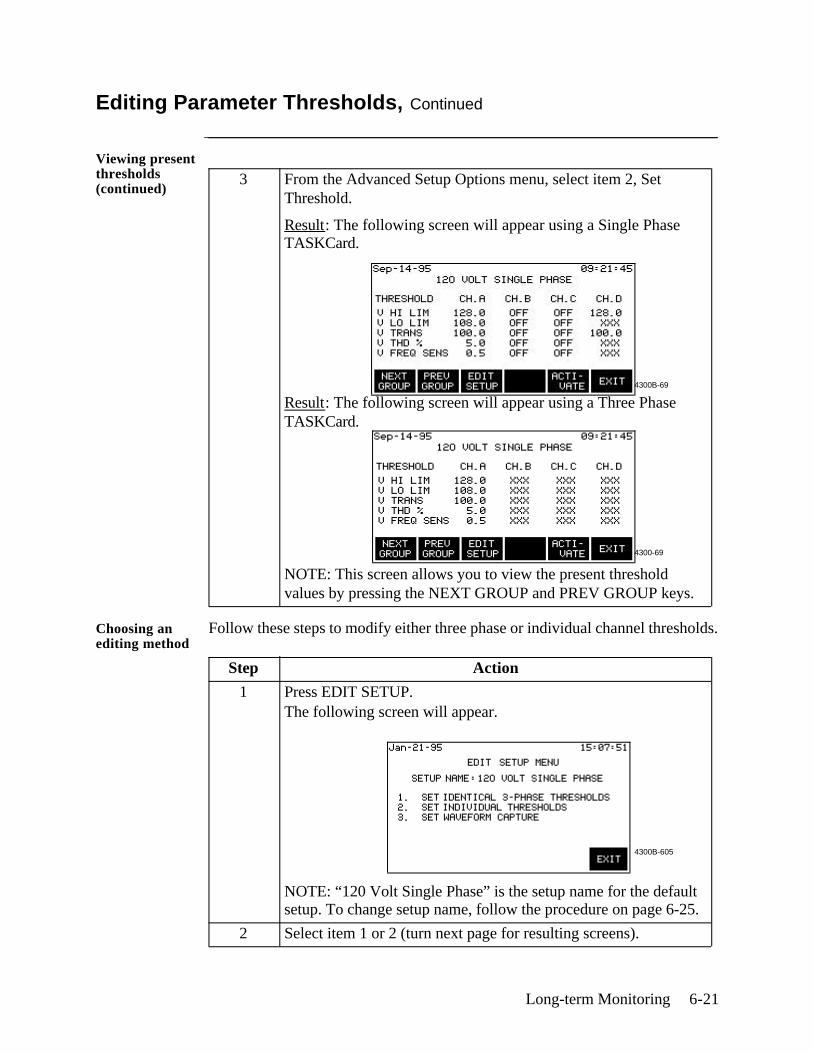
Long-term Monitoring 6-21
4300B-69
Editing Parameter Thresholds, Continued
Viewing present thresholds (continued)
Choosing an editing method
Follow these steps to modify either three phase or individual channel thresholds.
3 From the Advanced Setup Options menu, select item 2, Set Threshold.
Result: The following screen will appear using a Single Phase TASKCard.
Result: The following screen will appear using a Three Phase TASKCard.
NOTE: This screen allows you to view the present threshold values by pressing the NEXT GROUP and PREV GROUP keys.
Step Action
1 Press EDIT SETUP.The following screen will appear.
NOTE: “120 Volt Single Phase” is the setup name for the default setup. To change setup name, follow the procedure on page 6-25.
2 Select item 1 or 2 (turn next page for resulting screens).
4300-69
4300B-605
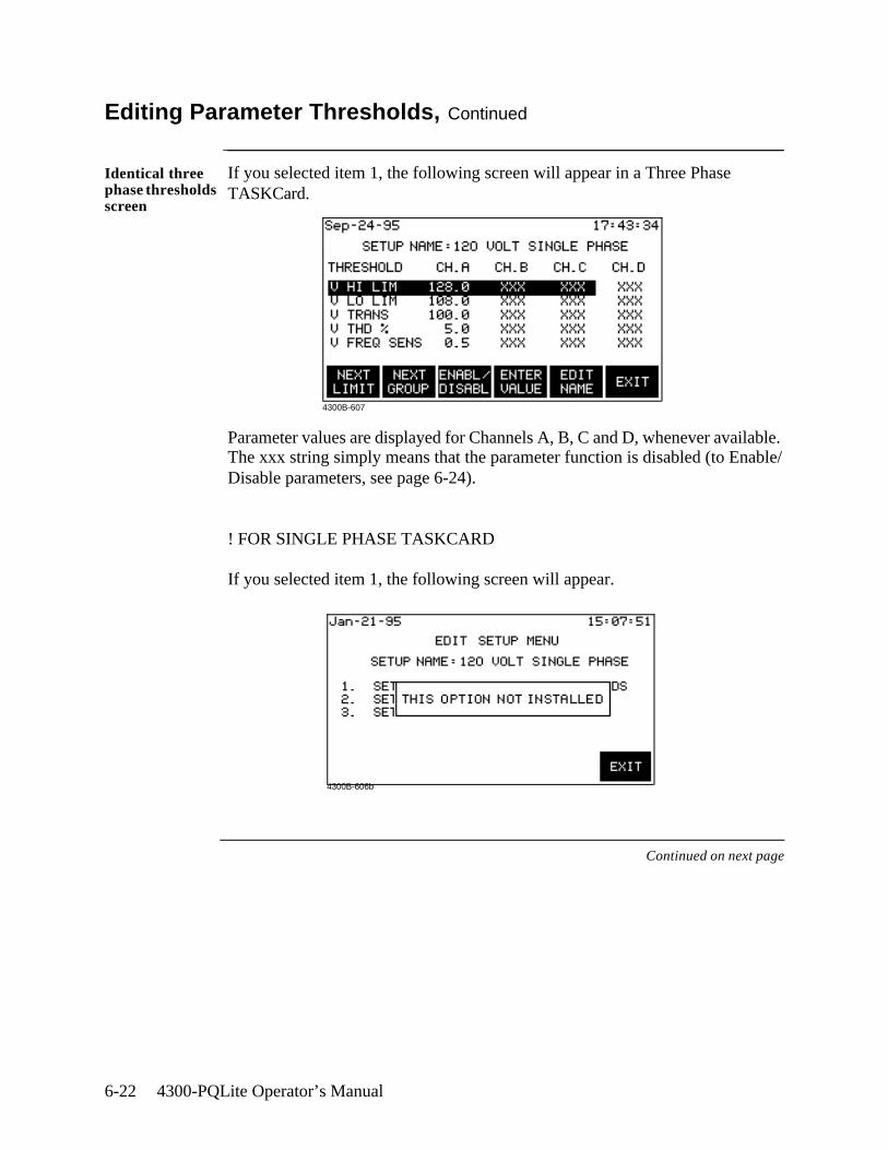
6-22 4300-PQLite Operator’s Manual
Editing Parameter Thresholds, Continued
Identical three phase thresholds screen
If you selected item 1, the following screen will appear in a Three Phase TASKCard.
Parameter values are displayed for Channels A, B, C and D, whenever available. The xxx string simply means that the parameter function is disabled (to Enable/Disable parameters, see page 6-24).
! FOR SINGLE PHASE TASKCARD
If you selected item 1, the following screen will appear.
Continued on next page
4300B-607
4300B-606b

Long-term Monitoring 6-23
Editing Parameter Thresholds, Continued
Individual channel thresholds screen
If you selected item 2, the following screen will appear in a Three Phase TASKCard.
Parameter values are displayed for Channels A, B, C and D, whenever available. The xxx string simply means that the parameter function is disabled (to enable/disable parameters, see page 6-24).
! FOR SINGLE PHASE TASKCARD
If you selected item 2, the following screen will appear.
Parameter values are displayed for Channels A and D, whenever available. The xxx string simply means that the parameter function is disabled (to enable/disable parameters, see page 6-24).
On the other hand, Channels B and C are masked and set to OFF by default. They do not monitor nor record any data.
Continued on next page
4300B-608
4300B-609
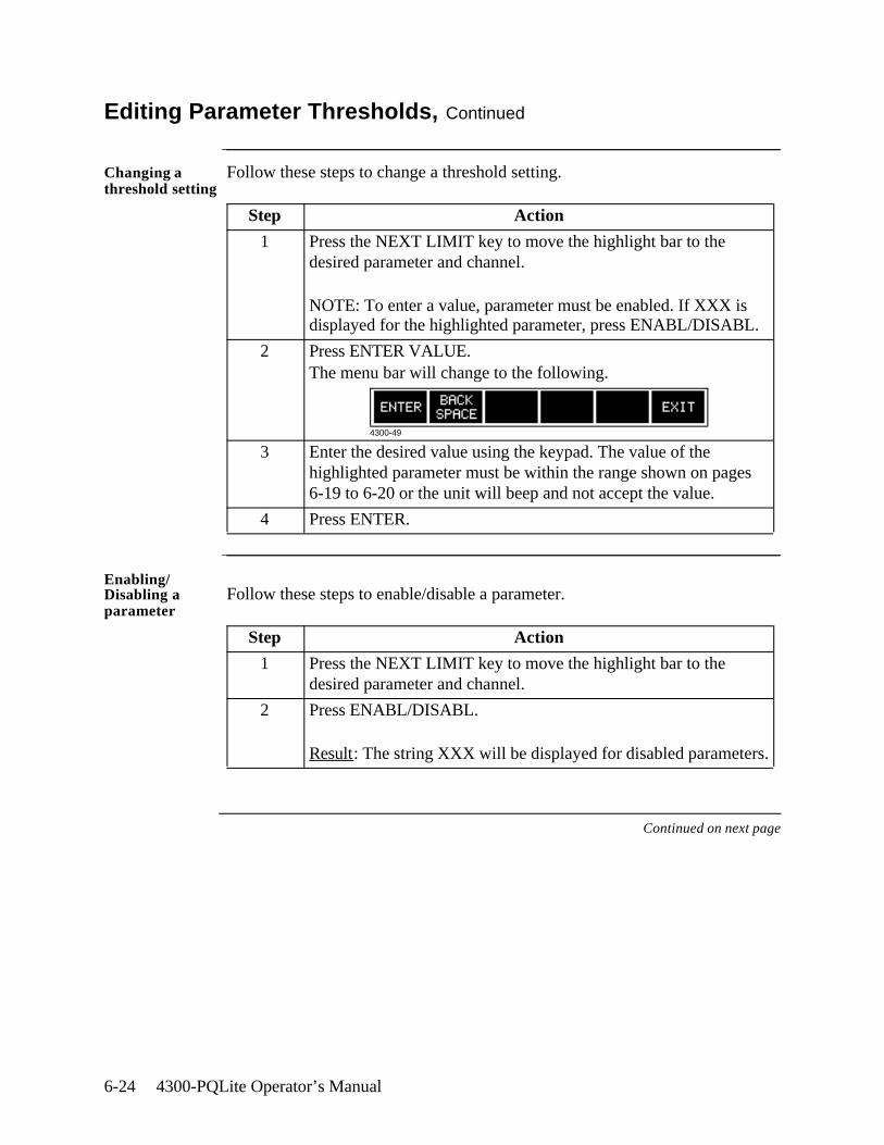
6-24 4300-PQLite Operator’s Manual
Editing Parameter Thresholds, Continued
Changing a threshold setting
Follow these steps to change a threshold setting.
Enabling/ Disabling a parameter
Follow these steps to enable/disable a parameter.
Continued on next page
Step Action
1 Press the NEXT LIMIT key to move the highlight bar to the desired parameter and channel.
NOTE: To enter a value, parameter must be enabled. If XXX is displayed for the highlighted parameter, press ENABL/DISABL.
2 Press ENTER VALUE. The menu bar will change to the following.
3 Enter the desired value using the keypad. The value of the highlighted parameter must be within the range shown on pages 6-19 to 6-20 or the unit will beep and not accept the value.
4 Press ENTER.
Step Action
1 Press the NEXT LIMIT key to move the highlight bar to the desired parameter and channel.
2 Press ENABL/DISABL.
Result: The string XXX will be displayed for disabled parameters.
4300-49
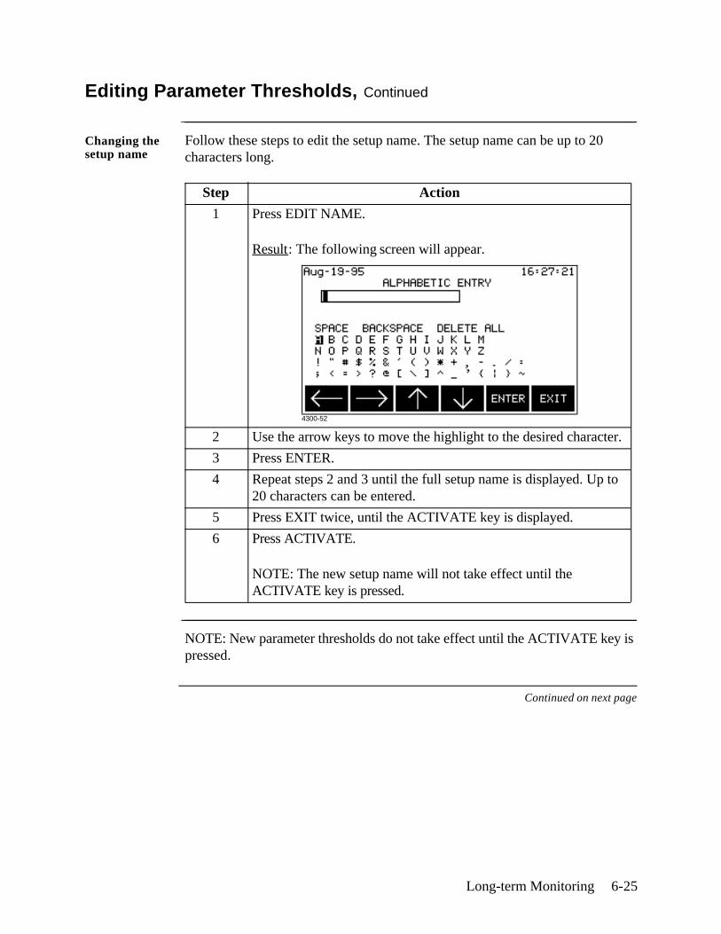
Long-term Monitoring 6-25
Editing Parameter Thresholds, Continued
Changing the setup name
Follow these steps to edit the setup name. The setup name can be up to 20 characters long.
NOTE: New parameter thresholds do not take effect until the ACTIVATE key is pressed.
Continued on next page
Step Action
1 Press EDIT NAME.
Result: The following screen will appear.
2 Use the arrow keys to move the highlight to the desired character.
3 Press ENTER.
4 Repeat steps 2 and 3 until the full setup name is displayed. Up to 20 characters can be entered.
5 Press EXIT twice, until the ACTIVATE key is displayed.
6 Press ACTIVATE.
NOTE: The new setup name will not take effect until the ACTIVATE key is pressed.
4300-52
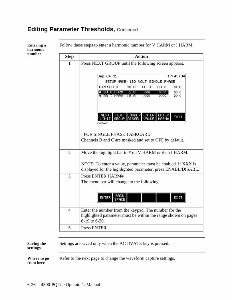
6-26 4300-PQLite Operator’s Manual
Editing Parameter Thresholds, Continued
Entering a harmonic number
Follow these steps to enter a harmonic number for V HARM or I HARM.
Saving the settings
Settings are saved only when the ACTIVATE key is pressed.
Where to go from here
Refer to the next page to change the waveform capture settings.
Step Action
1 Press NEXT GROUP until the following screen appears.
! FOR SINGLE PHASE TASKCARDChannels B and C are masked and set to OFF by default.
2 Move the highlight bar to # nn V HARM or # nn I HARM.
NOTE: To enter a value, parameter must be enabled. If XXX is displayed for the highlighted parameter, press ENABL/DISABL.
3 Press ENTER HARM#.The menu bar will change to the following.
4 Enter the number from the keypad. The number for the highlighted parameter must be within the range shown on pages 6-19 to 6-20.
5 Press ENTER.
4300B-610
Long-term Monitoring 6-27
Setting Waveform Capture
Definition Waveform capture is a function that saves waveform data when an event is triggered by a threshold crossing. This function can be set so that waveforms from the triggered channel, from all channels, or from no channels are saved.
NOTE: Waveform capture must be individually set for each parameter listed on pages 6-19 to 6-20.
Combinations The following table lists all the combinations available for waveform capture, and describes each setting.
Displaying the screen
Follow these steps to display the waveform capture screen.
Continued on next page
Wave Capture Record All Channels Description
ON ON Saves waveform data for all channels for the chosen parameter.
ON OFF Saves waveform data for the triggered channel only.
OFF ON Invalid combination.
OFF OFF No waveform data is saved.
Step Action
1 From the Scope Mode screen, press SETUP.
2 From the Setup Menu, select item 5, Advanced Setup Options.
3 From the Advanced Setup Options menu, select item 2, Set Threshold.
4 From the setup screen, press EDIT SETUP.
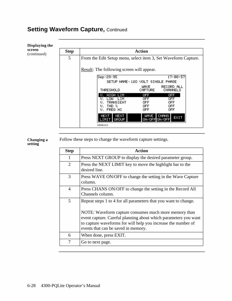
6-28 4300-PQLite Operator’s Manual
Setting Waveform Capture, Continued
Displaying the screen (continued)
Changing a setting
Follow these steps to change the waveform capture settings.
.
Step Action
5 From the Edit Setup menu, select item 3, Set Waveform Capture.
Result: The following screen will appear.
Step Action
1 Press NEXT GROUP to display the desired parameter group.
2 Press the NEXT LIMIT key to move the highlight bar to the desired line.
3 Press WAVE ON/OFF to change the setting in the Wave Capture column.
4 Press CHANS ON/OFF to change the setting in the Record All Channels column.
5 Repeat steps 1 to 4 for all parameters that you want to change.
NOTE: Waveform capture consumes much more memory than event capture. Careful planning about which parameters you want to capture waveforms for will help you increase the number of events that can be saved in memory.
6 When done, press EXIT.
7 Go to next page.
4300B-611
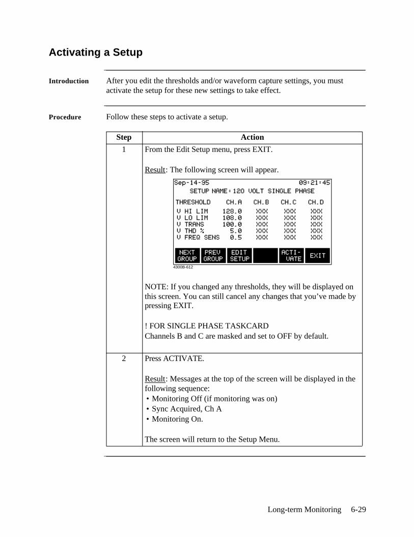
Long-term Monitoring 6-29
Activating a Setup
Introduction After you edit the thresholds and/or waveform capture settings, you must activate the setup for these new settings to take effect.
Procedure Follow these steps to activate a setup.
Step Action
1 From the Edit Setup menu, press EXIT.
Result: The following screen will appear.
NOTE: If you changed any thresholds, they will be displayed on this screen. You can still cancel any changes that you’ve made by pressing EXIT.
! FOR SINGLE PHASE TASKCARDChannels B and C are masked and set to OFF by default.
2 Press ACTIVATE.
Result: Messages at the top of the screen will be displayed in the following sequence:• Monitoring Off (if monitoring was on)• Sync Acquired, Ch A• Monitoring On.
The screen will return to the Setup Menu.
4300B-612
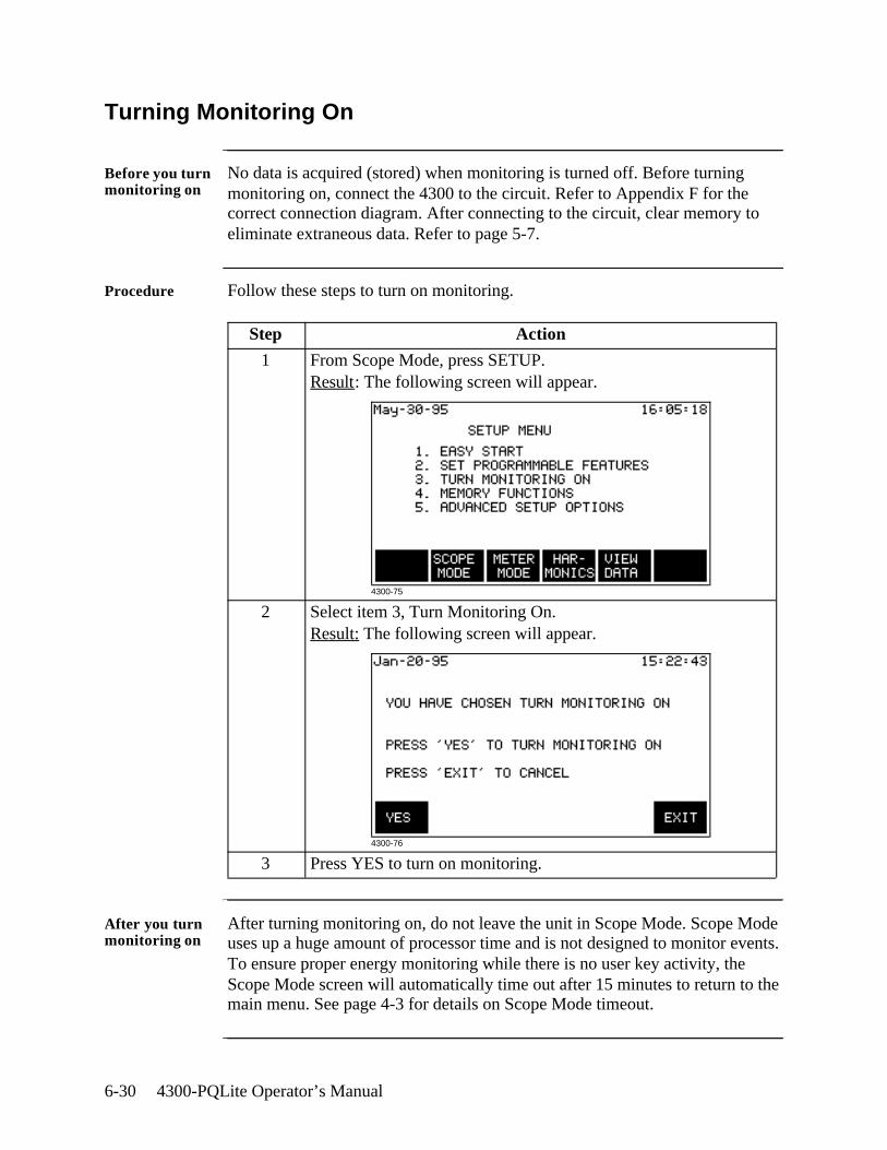
6-30 4300-PQLite Operator’s Manual
Turning Monitoring On
Before you turn monitoring on
No data is acquired (stored) when monitoring is turned off. Before turning monitoring on, connect the 4300 to the circuit. Refer to Appendix F for the correct connection diagram. After connecting to the circuit, clear memory to eliminate extraneous data. Refer to page 5-7.
Procedure Follow these steps to turn on monitoring.
After you turn monitoring on
After turning monitoring on, do not leave the unit in Scope Mode. Scope Mode uses up a huge amount of processor time and is not designed to monitor events. To ensure proper energy monitoring while there is no user key activity, the Scope Mode screen will automatically time out after 15 minutes to return to the main menu. See page 4-3 for details on Scope Mode timeout.
Step Action
1 From Scope Mode, press SETUP.Result: The following screen will appear.
2 Select item 3, Turn Monitoring On.Result: The following screen will appear.
3 Press YES to turn on monitoring.
4300-75
4300-76

Saving Data 7-1
Chapter 7
Saving Data
Overview
Where you can save data
The 4300 allows you to save data manually or automatically in two places: internal memory or the optional memory card.
Internal memory: Data is always saved automatically in the internal memory when monitoring is on. Data can be saved manually in the internal memory by pressing the SAVE key on the Scope or Meter mode screens.
Memory card: Data is saved automatically on the optional memory card when the Auto-Transfer mode is enabled. It can be saved manually by using the Write Events function on the Memory Card Functions screen.
In this chapter The following topics are covered in this chapter.
Topic See Page
Setting Memory Storage Mode 7-2
Automatically Saving Data to a Memory Card 7-3
Manually Saving Data to a Memory Card 7-5
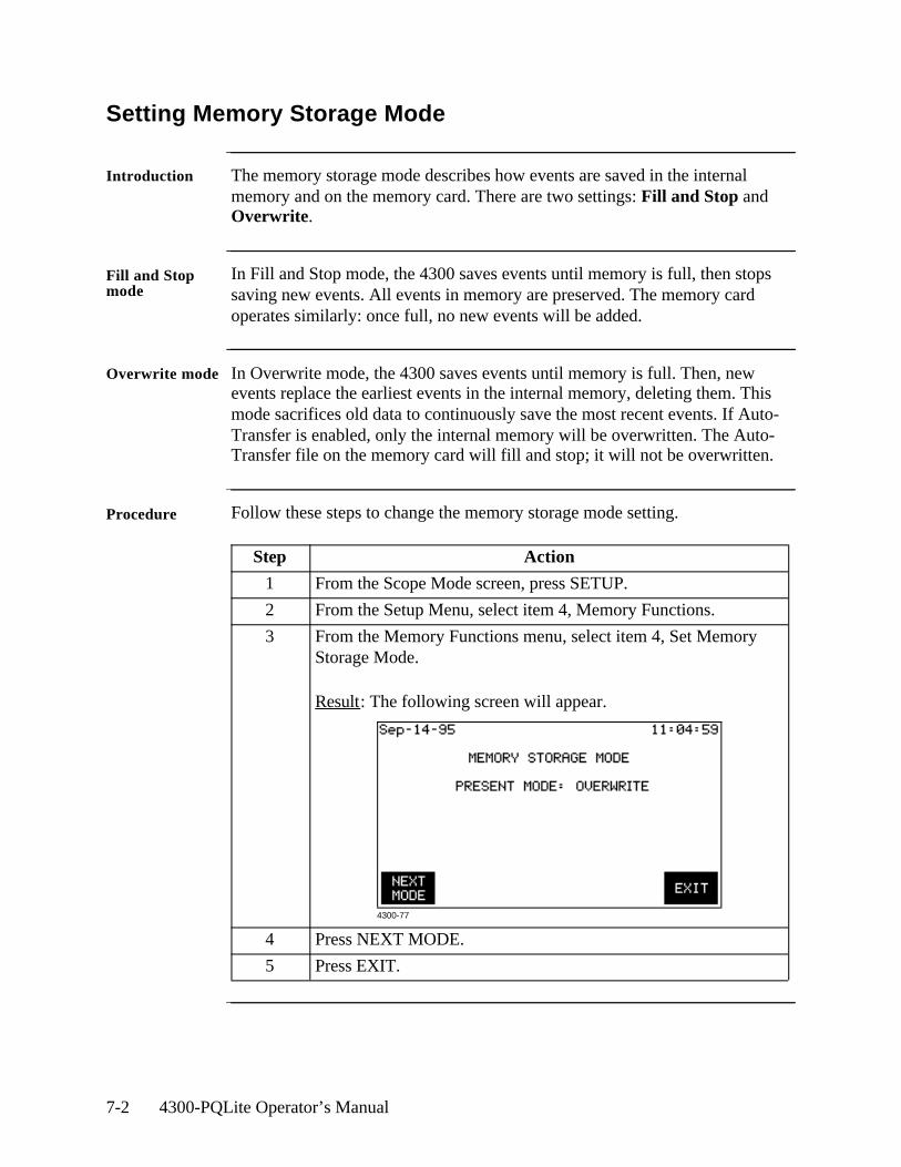
7-2 4300-PQLite Operator’s Manual
Setting Memory Storage Mode
Introduction The memory storage mode describes how events are saved in the internal memory and on the memory card. There are two settings: Fill and Stop and Overwrite.
Fill and Stop mode
In Fill and Stop mode, the 4300 saves events until memory is full, then stops saving new events. All events in memory are preserved. The memory card operates similarly: once full, no new events will be added.
Overwrite mode In Overwrite mode, the 4300 saves events until memory is full. Then, new events replace the earliest events in the internal memory, deleting them. This mode sacrifices old data to continuously save the most recent events. If Auto-Transfer is enabled, only the internal memory will be overwritten. The Auto-Transfer file on the memory card will fill and stop; it will not be overwritten.
Procedure Follow these steps to change the memory storage mode setting.
Step Action
1 From the Scope Mode screen, press SETUP.
2 From the Setup Menu, select item 4, Memory Functions.
3 From the Memory Functions menu, select item 4, Set Memory Storage Mode.
Result: The following screen will appear.
4 Press NEXT MODE.
5 Press EXIT.
4300-77
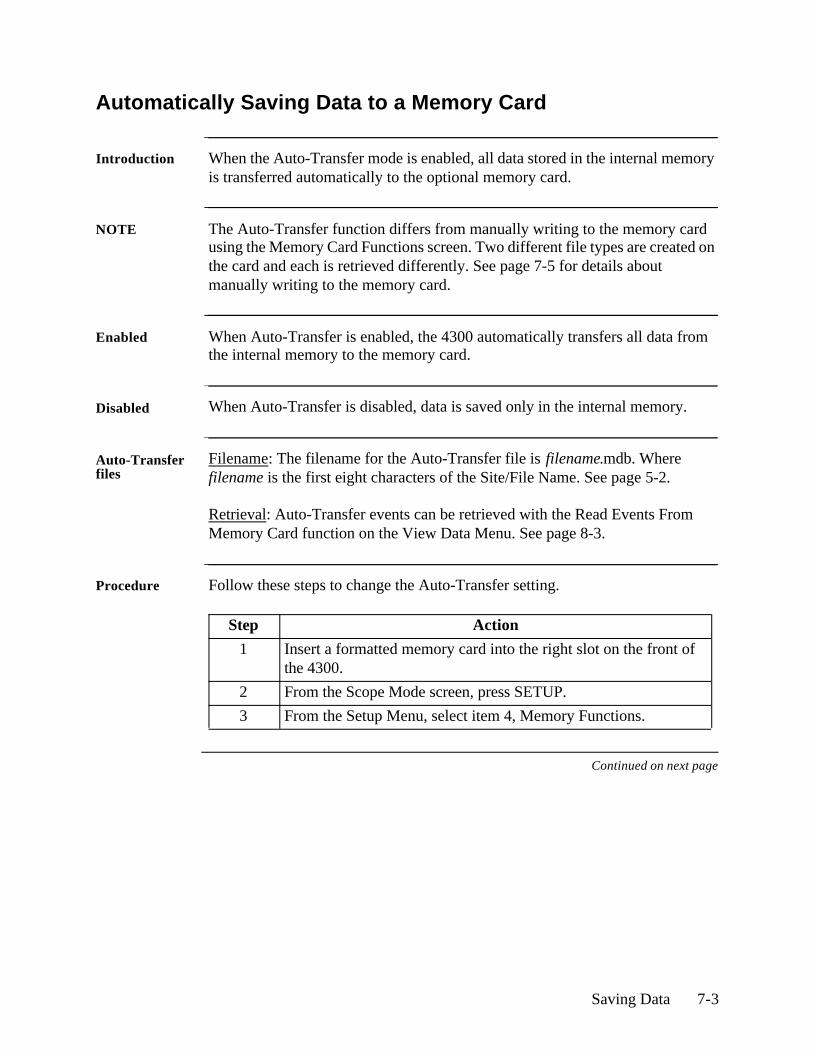
Saving Data 7-3
Automatically Saving Data to a Memory Card
Introduction When the Auto-Transfer mode is enabled, all data stored in the internal memory is transferred automatically to the optional memory card.
NOTE The Auto-Transfer function differs from manually writing to the memory card using the Memory Card Functions screen. Two different file types are created on the card and each is retrieved differently. See page 7-5 for details about manually writing to the memory card.
Enabled When Auto-Transfer is enabled, the 4300 automatically transfers all data from the internal memory to the memory card.
Disabled When Auto-Transfer is disabled, data is saved only in the internal memory.
Auto-Transfer files
Filename: The filename for the Auto-Transfer file is filename.mdb. Where filename is the first eight characters of the Site/File Name. See page 5-2.
Retrieval: Auto-Transfer events can be retrieved with the Read Events From Memory Card function on the View Data Menu. See page 8-3.
Procedure Follow these steps to change the Auto-Transfer setting.
Continued on next page
Step Action
1 Insert a formatted memory card into the right slot on the front of the 4300.
2 From the Scope Mode screen, press SETUP.
3 From the Setup Menu, select item 4, Memory Functions.
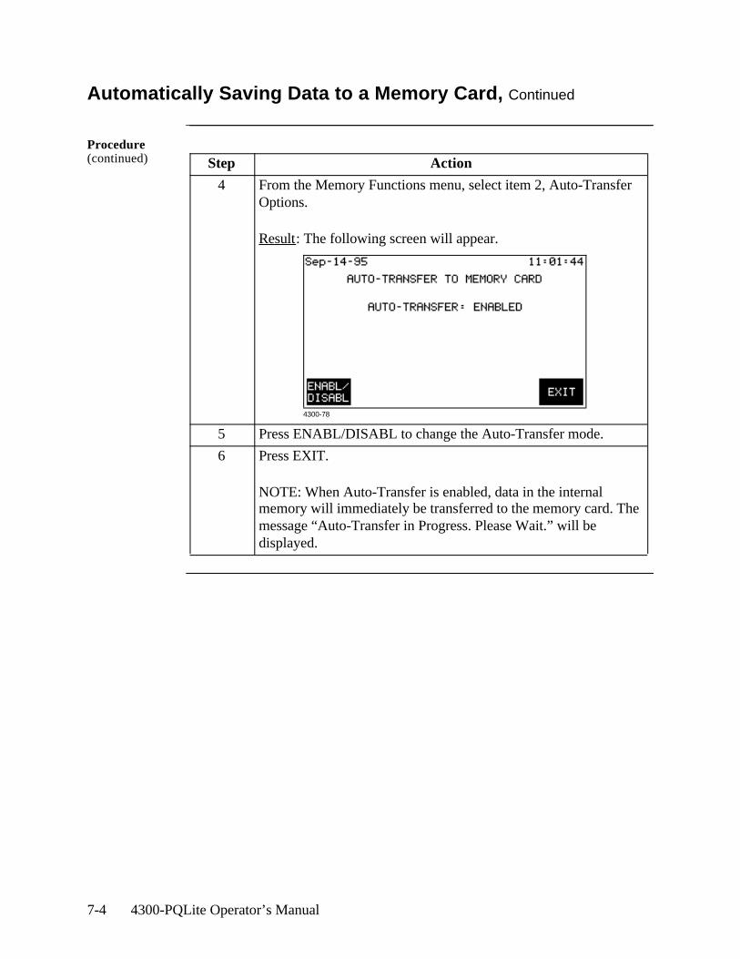
7-4 4300-PQLite Operator’s Manual
Automatically Saving Data to a Memory Card, Continued
Procedure (continued) Step Action
4 From the Memory Functions menu, select item 2, Auto-Transfer Options.
Result: The following screen will appear.
5 Press ENABL/DISABL to change the Auto-Transfer mode.
6 Press EXIT.
NOTE: When Auto-Transfer is enabled, data in the internal memory will immediately be transferred to the memory card. The message “Auto-Transfer in Progress. Please Wait.” will be displayed.
4300-78
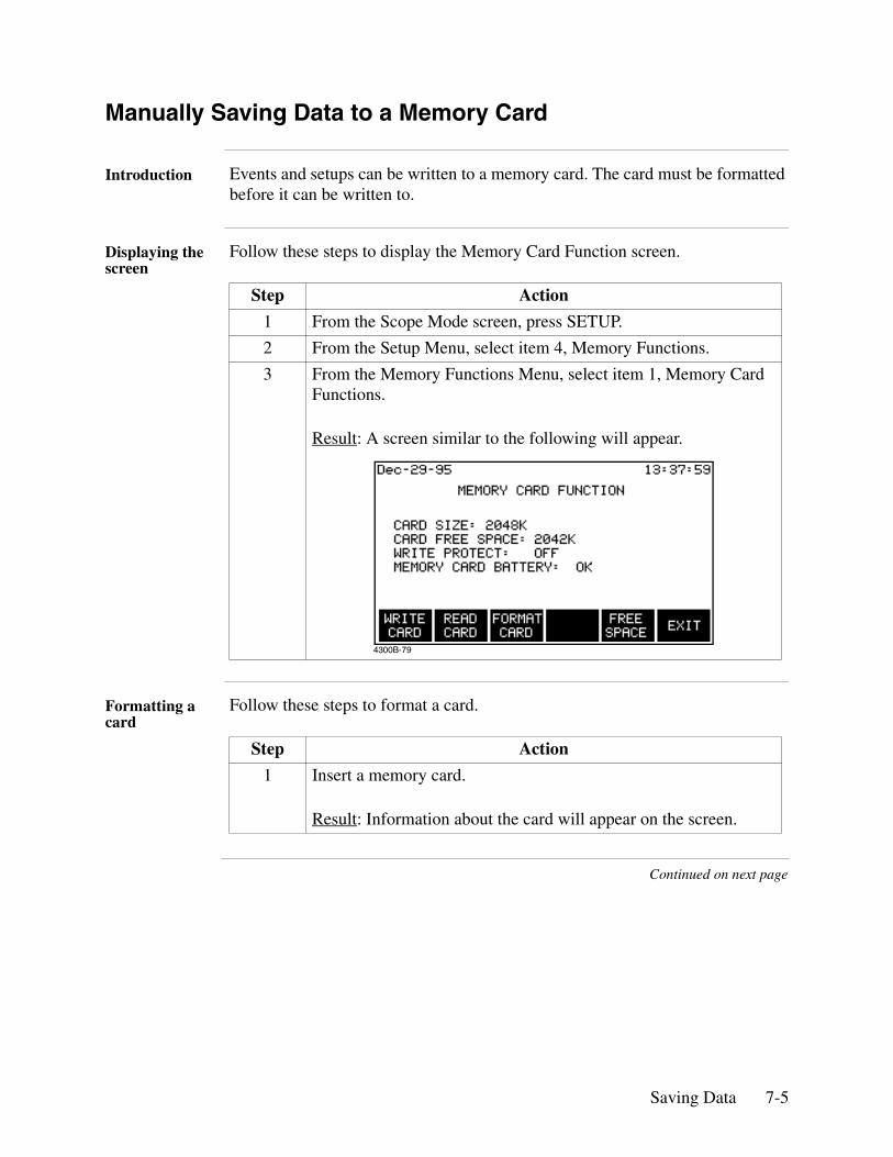
Saving Data 7-5
Manually Saving Data to a Memory Card
Introduction Events and setups can be written to a memory card. The card must be formatted before it can be written to.
Displaying the screen
Follow these steps to display the Memory Card Function screen.
Formatting a card
Follow these steps to format a card.
Continued on next page
Step Action
1 From the Scope Mode screen, press SETUP.
2 From the Setup Menu, select item 4, Memory Functions.
3 From the Memory Functions Menu, select item 1, Memory Card Functions.
Result: A screen similar to the following will appear.
Step Action
1 Insert a memory card.
Result: Information about the card will appear on the screen.
4300B-79
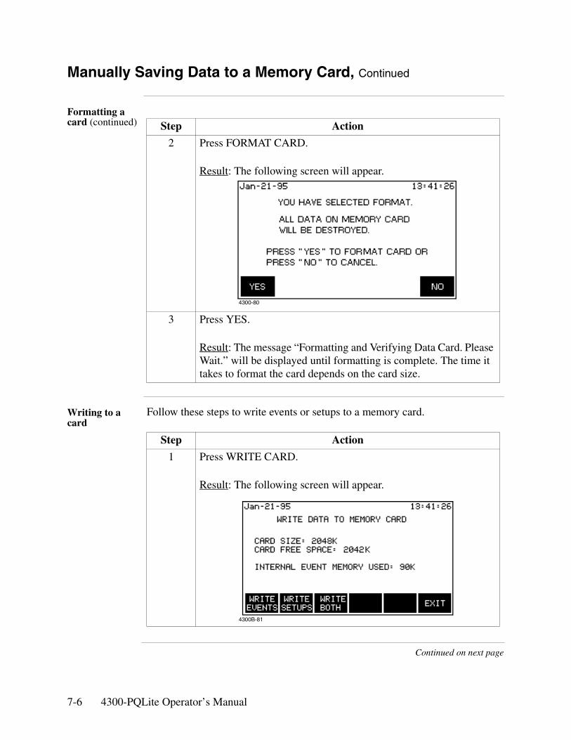
7-6 4300-PQLite Operator’s Manual
Manually Saving Data to a Memory Card, Continued
Formatting a card (continued)
Writing to a card
Follow these steps to write events or setups to a memory card.
Continued on next page
Step Action
2 Press FORMAT CARD.
Result: The following screen will appear.
3 Press YES.
Result: The message “Formatting and Verifying Data Card. Please Wait.” will be displayed until formatting is complete. The time it takes to format the card depends on the card size.
Step Action
1 Press WRITE CARD.
Result: The following screen will appear.
4300-80
4300B-81
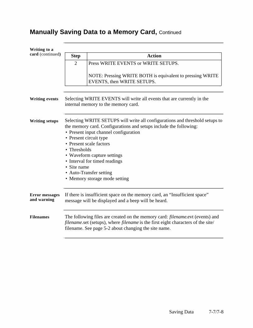
Saving Data 7-7/7-8
Manually Saving Data to a Memory Card, Continued
Writing to a card (continued)
Writing events Selecting WRITE EVENTS will write all events that are currently in the internal memory to the memory card.
Writing setups Selecting WRITE SETUPS will write all configurations and threshold setups to the memory card. Configurations and setups include the following:• Present input channel configuration• Present circuit type• Present scale factors• Thresholds• Waveform capture settings• Interval for timed readings• Site name• Auto-Transfer setting• Memory storage mode setting
Error messages and warning
If there is insufficient space on the memory card, an “Insufficient space” message will be displayed and a beep will be heard.
Filenames The following files are created on the memory card: filename.evt (events) and filename.set (setups), where filename is the first eight characters of the site/filename. See page 5-2 about changing the site name.
Step Action
2 Press WRITE EVENTS or WRITE SETUPS.
NOTE: Pressing WRITE BOTH is equivalent to pressing WRITE EVENTS, then WRITE SETUPS.

7-8 4300-PQLite Operator’s Manual
Viewing Data 8-1
Chapter 8
Viewing Data
Overview
Types of data displays
The 4300 displays data in three forms: graphic summaries, events, and waveforms.
Graphic summaries: These are plots of many events over time. They can be zoomed in on to show more detail.
Events: These are text descriptions of the events which can be one line in an event report or a whole event details screen.
Waveforms: These are the actual voltage or current waveforms that occurred at the time of an event. One or three cycles are displayed depending on the parameter.
What data to view?
Data can only be viewed from the internal memory, but it can be saved to either internal memory or a memory card (see Chapter 7). Two types of data files can be stored on a card: an Auto-Transfer file and an event file. To view data stored on a memory card, it must first be copied into the internal memory. When data files are copied into the internal memory, any existing data in the internal memory is deleted.
Downloading and viewing data on a computer
DRAN-LINKTM is the communications software used to download events from the PP4300 to the computer. While DRAN-VIEW® is the program required to view data on the computer. Both applications are directly interfaced. See Downloading Events from 4300 to a Computer - Software Requirements on page 8-34 for more information.
Dranetz-BMI is the owner and distributor of the DRAN-LINKTM and DRAN-VIEW® product applications. For pricing and availability, contact Dranetz Customer Service Department at (732) 287-3680 or 1-800-DRANTEC.
8-2 4300-PQLite Operator’s Manual
Overview, continued
In this chapter This chapter is divided into four sections.
Section Title See Page
A Copying Memory Card Files into Internal Memory 8-3
B Graphic Summaries 8-9
C Events 8-18
D Event Waveforms 8-27
E Downloading Events from 4300 to a Computer 8-32
Viewing Data 8-3
Section A
Copying Memory Card Files into Internal Memory
Overview
File types In order to view data that is stored on a memory card, you must first copy it into memory. There are two data files that could possibly be on a memory card: an Auto-Transfer file and an Event file.
Auto-Transfer file: An Auto-Transfer file is created when the Auto-Transfer mode is enabled. See page 7-3.
Event file: An Event file (.evt) is created when you use the Write to memory card function. See page 7-6.
Caution Copying a file from the memory card will delete all data in memory. Save any important data before proceeding. See page 7-5 for information about manually saving your data.
Precaución Si se copia un archivo de la tarjeta de memoria se suprimirán todos los datos en la memoria. Guarde todos los datos importantes antes de proceder. Consulte la página 7-5 para información acerca de guardar sus datos manualmente.
Mise en garde Le fait de copier un fichier à partir de la carte à mémoire entraînera l’effacement de l’ensemble des données de la mémoire. Sauvegardez les données importantes avant de poursuivre. Consultez la page 7-5 pour savoir comment sauvegarder manuellement vos données.
Vorsicht Durch das Kopieren einer Datei von der Speicherkarte werden alle Daten im Arbeitsspeicher gelöscht. Speichern Sie deshalb alle wichtigen Daten, bevor Sie fortfahren. Informationen zum manuellen Speichern von Daten finden Sie auf Seite 7-5.
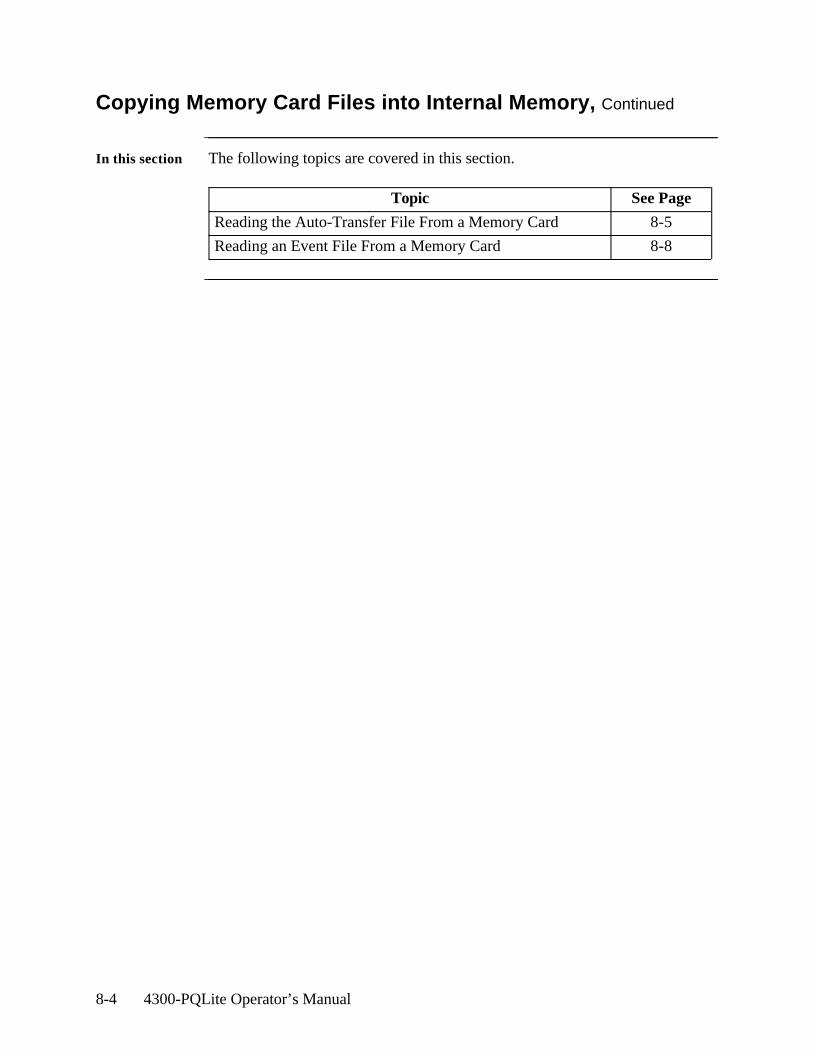
8-4 4300-PQLite Operator’s Manual
Copying Memory Card Files into Internal Memory, Continued
In this section The following topics are covered in this section.
Topic See Page
Reading the Auto-Transfer File From a Memory Card 8-5
Reading an Event File From a Memory Card 8-8
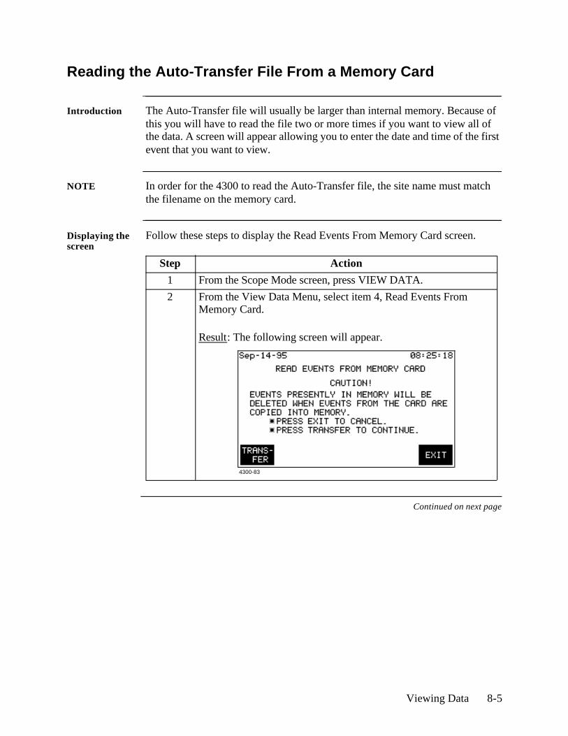
Viewing Data 8-5
Reading the Auto-Transfer File From a Memory Card
Introduction The Auto-Transfer file will usually be larger than internal memory. Because of this you will have to read the file two or more times if you want to view all of the data. A screen will appear allowing you to enter the date and time of the first event that you want to view.
NOTE In order for the 4300 to read the Auto-Transfer file, the site name must match the filename on the memory card.
Displaying the screen
Follow these steps to display the Read Events From Memory Card screen.
Continued on next page
Step Action
1 From the Scope Mode screen, press VIEW DATA.
2 From the View Data Menu, select item 4, Read Events From Memory Card.
Result: The following screen will appear.
4300-83
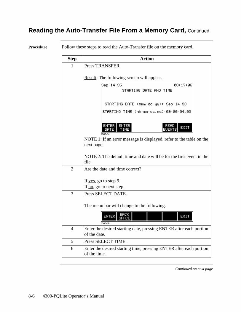
8-6 4300-PQLite Operator’s Manual
Reading the Auto-Transfer File From a Memory Card, Continued
Procedure Follow these steps to read the Auto-Transfer file on the memory card.
Continued on next page
Step Action
1 Press TRANSFER.
Result: The following screen will appear.
NOTE 1: If an error message is displayed, refer to the table on the next page.
NOTE 2: The default time and date will be for the first event in the file.
2 Are the date and time correct?
If yes, go to step 9.If no, go to next step.
3 Press SELECT DATE.
The menu bar will change to the following.
4 Enter the desired starting date, pressing ENTER after each portion of the date.
5 Press SELECT TIME.
6 Enter the desired starting time, pressing ENTER after each portion of the time.
4300-84
4300-49
Viewing Data 8-7
Reading the Auto-Transfer File From a Memory Card, Continued
Procedure (continued)
Error messages The following error messages may be displayed when the TRANSFER key is pressed.
Step Action
7 Press READ EVENTS.
NOTE: If the card contains more data than can fit in memory, only as much as possible will be copied. After viewing the initial batch of data, note the date and time of the last event. Enter these values into the starting date and time screen to read the rest of the data.
Error Message Description
MEMORY CARD NOT FOUND!NO DATA TRANSFERRED
No memory card inserted or inserted improperly.
DATA FILE CORRUPTED!NO DATA TRANSFERRED.
The 4300 started to read a memory card file but detected an error in the data.
EMPTY MEMORY CARD DATABASE!NO DATA TRANSFERRED.
A valid database has been saved to the memory card but no events exist.
WRONG DATABASE VERSION!NO DATA TRANSFERRED.
The 4300 cannot read the database version on the memory card.
FILE NOT FOUND!NO DATA TRANSFERRED.
No file with the correct name on the memory card. The present site name must match the filename on the memory card. Memory card files use the first 8 characters of the site name. To change site name, see page 5-2.
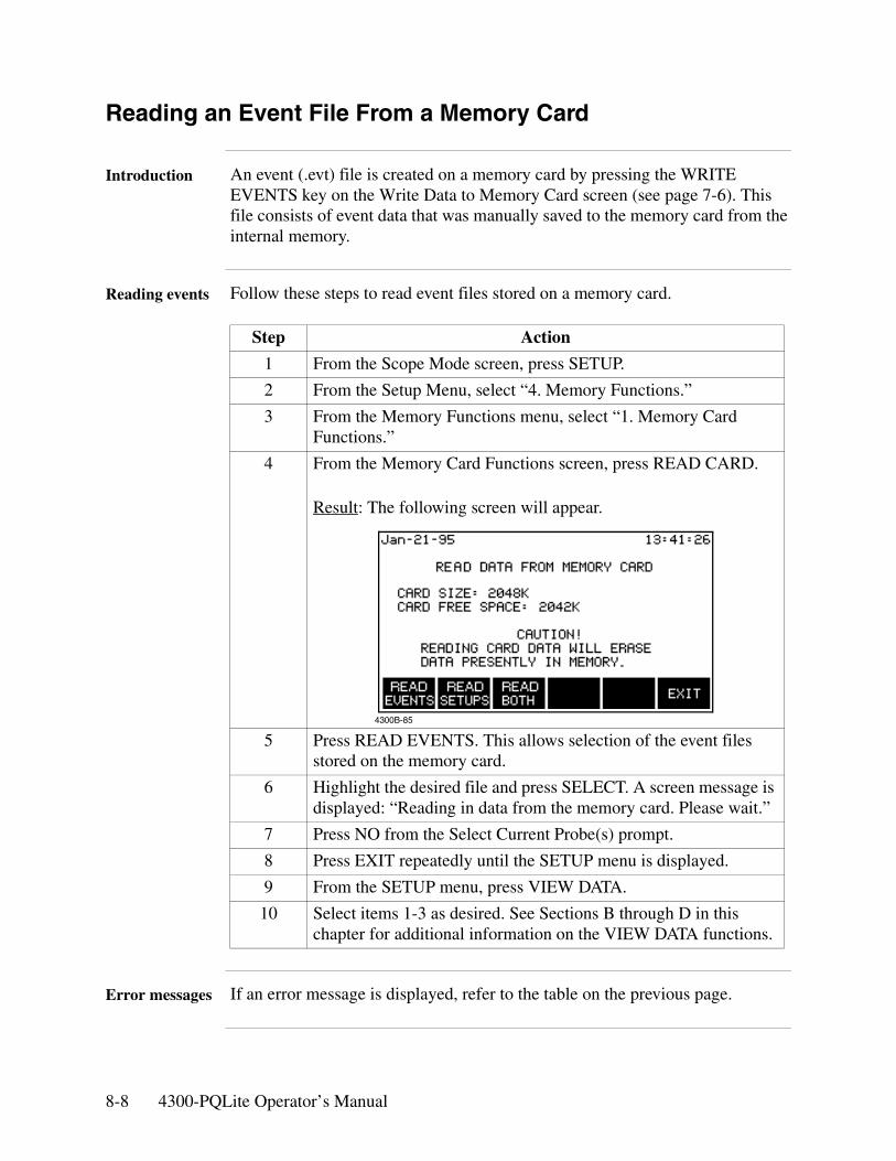
8-8 4300-PQLite Operator’s Manual
Reading an Event File From a Memory Card
Introduction An event (.evt) file is created on a memory card by pressing the WRITE EVENTS key on the Write Data to Memory Card screen (see page 7-6). This file consists of event data that was manually saved to the memory card from the internal memory.
Reading events Follow these steps to read event files stored on a memory card.
Error messages If an error message is displayed, refer to the table on the previous page.
Step Action
1 From the Scope Mode screen, press SETUP.
2 From the Setup Menu, select “4. Memory Functions.”
3 From the Memory Functions menu, select “1. Memory Card Functions.”
4 From the Memory Card Functions screen, press READ CARD.
Result: The following screen will appear.
5 Press READ EVENTS. This allows selection of the event files stored on the memory card.
6 Highlight the desired file and press SELECT. A screen message is displayed: “Reading in data from the memory card. Please wait.”
7 Press NO from the Select Current Probe(s) prompt.
8 Press EXIT repeatedly until the SETUP menu is displayed.
9 From the SETUP menu, press VIEW DATA.
10 Select items 1-3 as desired. See Sections B through D in this chapter for additional information on the VIEW DATA functions.
4300B-85
Viewing Data 8-9
Section B
Graphic Summaries
Overview
Type of graphic summaries
The 4300 can display two types of graphic summaries: time plots and an event activity plot. Both plots allow you to display an event report.
Time plots: A time plot is a graph of the value of one parameter and channel over time. There are 16 parameters and 4 channels that can be plotted. The time plot displays all data since the memory was cleared and is continuously updated. Other functions allow you to expand both the horizontal and vertical axes so that you can perform detailed analysis. You can also display an event report that lists the events that were used to draw the plot.
Event activity plot: This is a plot of the rate of occurrence for all the events in memory. The horizontal axis can be expanded and you can display an event report for all the events in memory.
In this section The following topics are covered in this section.
Topic See Page
Viewing Time Plots 8-10
Selecting a Parameter 8-12
Using Horizontal Zoom 8-13
Changing the Vertical Scale 8-15
Viewing the Event Activity Plot 8-17
8-10 4300-PQLite Operator’s Manual
Viewing Time Plots
What is displayed on a time plot?
A time plot consists of the timed and threshold events that have occurred since memory was cleared for the parameter displayed above the plot.
Screen redraw The time plot screen is redrawn every ten seconds.
Horizontal axis Auto-scaled to display all events of the given type.
Vertical axis Auto-scaled to the highest and lowest parameter values.
Channels A, B, C, D, ABC
Parameters The following parameters can be plotted on the time plot screen.• V rms• V transient• I rms• I transient• Watts• VA• VAR• Power Factor• V Freq• I Peak• V thd• I thd• V harm#__• I harm#__• K-Factor• V Unbalance
Continued on next page
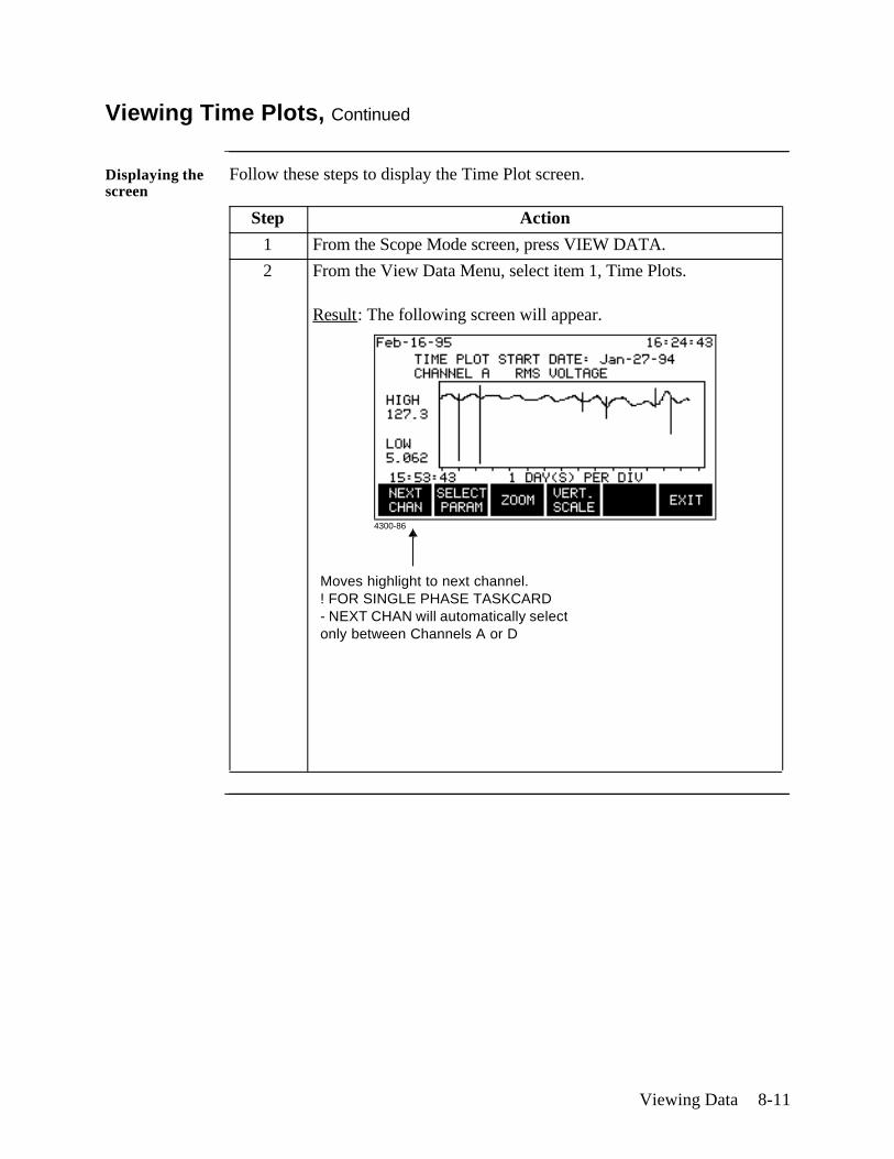
Viewing Data 8-11
Viewing Time Plots, Continued
Displaying the screen
Follow these steps to display the Time Plot screen.
Step Action
1 From the Scope Mode screen, press VIEW DATA.
2 From the View Data Menu, select item 1, Time Plots.
Result: The following screen will appear.
4300-86
Moves highlight to next channel.! FOR SINGLE PHASE TASKCARD- NEXT CHAN will automatically select only between Channels A or D
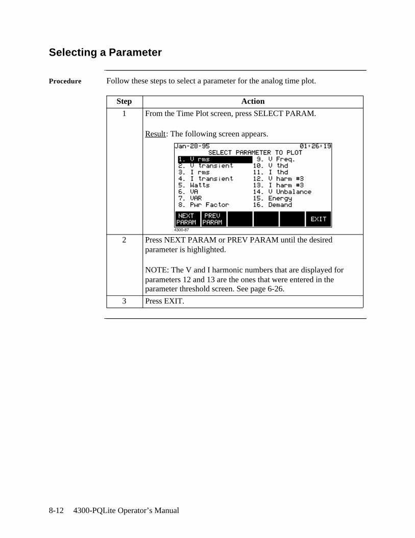
8-12 4300-PQLite Operator’s Manual
Selecting a Parameter
Procedure Follow these steps to select a parameter for the analog time plot.
Step Action
1 From the Time Plot screen, press SELECT PARAM.
Result: The following screen appears.
2 Press NEXT PARAM or PREV PARAM until the desired parameter is highlighted.
NOTE: The V and I harmonic numbers that are displayed for parameters 12 and 13 are the ones that were entered in the parameter threshold screen. See page 6-26.
3 Press EXIT.
4300-87
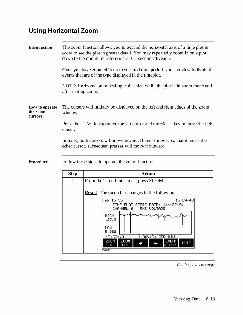
Viewing Data 8-13
Using Horizontal Zoom
Introduction The zoom function allows you to expand the horizontal axis of a time plot in order to see the plot in greater detail. You may repeatedly zoom in on a plot down to the minimum resolution of 0.1 seconds/division.
Once you have zoomed in on the desired time period, you can view individual events that are of the type displayed in the timeplot.
NOTE: Horizontal auto-scaling is disabled while the plot is in zoom mode and after exiting zoom.
How to operate the zoom cursors
The cursors will initially be displayed on the left and right edges of the zoom window.
Press the key to move the left cursor and the key to move the right cursor.
Initially, both cursors will move inward. If one is moved so that it meets the other cursor, subsequent presses will move it outward.
Procedure Follow these steps to operate the zoom function.
Continued on next page
Step Action
1 From the Time Plot screen, press ZOOM.
Result: The menu bar changes to the following.
4300-88
8-14 4300-PQLite Operator’s Manual
Using Horizontal Zoom, Continued
Procedure (continued)
Exiting Pressing the EXIT key returns you to the previous screen. The zoom resolution is maintained and auto-scaling is disabled until ZOOM OUT is pressed or you exit the timeplot screen and return. You can view zoomed plots of other channels and parameters.
Step Action
2 Select a time period using the zoom cursors.
3 Press ZOOM IN.
Result: The portion of the plot between the zoom cursors will now fill the entire screen.
4 Repeat steps 2 and 3 for finer resolution.
5 Press EVENT REPORT to display the first event to the right of the left cursor. See page 8-19.
6 ZOOM OUT re-draws the plot to the previous zoom level.

Viewing Data 8-15
Changing the Vertical Scale
Introduction The Set Vertical Scale screen allows you to enter your own values for the high and low limits on the time plot. This stops the vertical axis of the plot from auto scaling. Vertical axis auto scaling will resume when another parameter is selected, or the time plot screen is exited.
The scale values that you set will be retained for plots of other channels of the same parameter.
Procedure Follow these steps to change the vertical scale of a time plot.
Continued on next page
Step Action
1 From the Time Plot screen, press VERT SCALE.
Result: The following box will appear in front of the time plot.
2 Press SET HIGH.
The menu bar will change to the following.
3 Enter the high limit using the numeric keypad.
4 Press ENTER.
5 Press SET LOW.
6 Enter the low limit using the numeric keypad..
7 Press ENTER.
8 Press EXIT to accept the settings.
4300-89
4300-49

8-16 4300-PQLite Operator’s Manual
Changing the Vertical Scale, Continued
Ranges The ranges for the high and low values on the vertical scale are:
High: 0 to 9.999.000 but not lower than the low limit.
Low: 0 to 9,999,000 but not higher than the high limit.
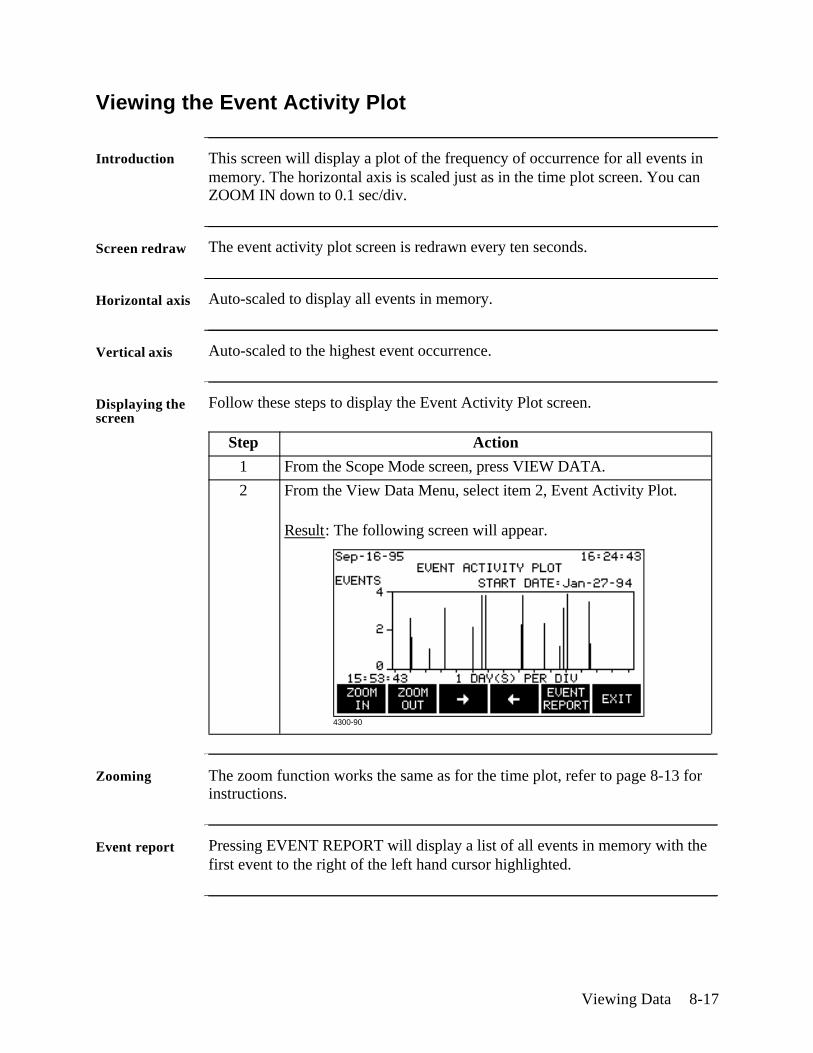
Viewing Data 8-17
Viewing the Event Activity Plot
Introduction This screen will display a plot of the frequency of occurrence for all events in memory. The horizontal axis is scaled just as in the time plot screen. You can ZOOM IN down to 0.1 sec/div.
Screen redraw The event activity plot screen is redrawn every ten seconds.
Horizontal axis Auto-scaled to display all events in memory.
Vertical axis Auto-scaled to the highest event occurrence.
Displaying the screen
Follow these steps to display the Event Activity Plot screen.
Zooming The zoom function works the same as for the time plot, refer to page 8-13 for instructions.
Event report Pressing EVENT REPORT will display a list of all events in memory with the first event to the right of the left hand cursor highlighted.
Step Action
1 From the Scope Mode screen, press VIEW DATA.
2 From the View Data Menu, select item 2, Event Activity Plot.
Result: The following screen will appear.
4300-90
8-18 4300-PQLite Operator’s Manual
Section C
Events
Overview
Introduction Events are the basic components of the different types of data that you can view on the 4300. Time plots and the event activity plot are graphic representations of the events in memory. Waveforms are optional; they cannot exist without an associated event. An event can be viewed two ways: as a one-line summary in an event list or a complete description on an event details screen.
Report types There are two types of event lists: the event report and worst case events.
Event report: The event report can either list all events in memory as accessed from the Event Activity Plot screen, or list all of the events that were used to make a particular time plot as accessed from the time plot screen. For example, the event report for a voltage rms time plot would list voltage rms events only; no current, power, harmonic, etc. events would be listed.
Worst case events: This is a list of the four worst events for nine parameters. It is accessed from the View Data menu.
In this section The following topics are covered in this section.
Topic See Page
Viewing the Event Report 8-19
Event Descriptions 8-20
Viewing Worst Case Events 8-23
Viewing Event Details 8-25
IEEE 1159 Classifications 8-26
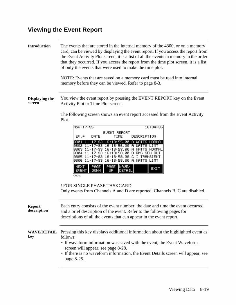
Viewing Data 8-19
Viewing the Event Report
Introduction The events that are stored in the internal memory of the 4300, or on a memory card, can be viewed by displaying the event report. If you access the report from the Event Activity Plot screen, it is a list of all the events in memory in the order that they occurred. If you access the report from the time plot screen, it is a list of only the events that were used to make the time plot.
NOTE: Events that are saved on a memory card must be read into internal memory before they can be viewed. Refer to page 8-3.
Displaying the screen
You view the event report by pressing the EVENT REPORT key on the Event Activity Plot or Time Plot screen.
The following screen shows an event report accessed from the Event Activity Plot.
! FOR SINGLE PHASE TASKCARDOnly events from Channels A and D are reported. Channels B, C are disabled.
Report description
Each entry consists of the event number, the date and time the event occurred, and a brief description of the event. Refer to the following pages for descriptions of all the events that can appear in the event report.
WAVE/DETAIL key
Pressing this key displays additional information about the highlighted event as follows:• If waveform information was saved with the event, the Event Waveform
screen will appear, see page 8-28. • If there is no waveform information, the Event Details screen will appear, see
page 8-25.
4300-91
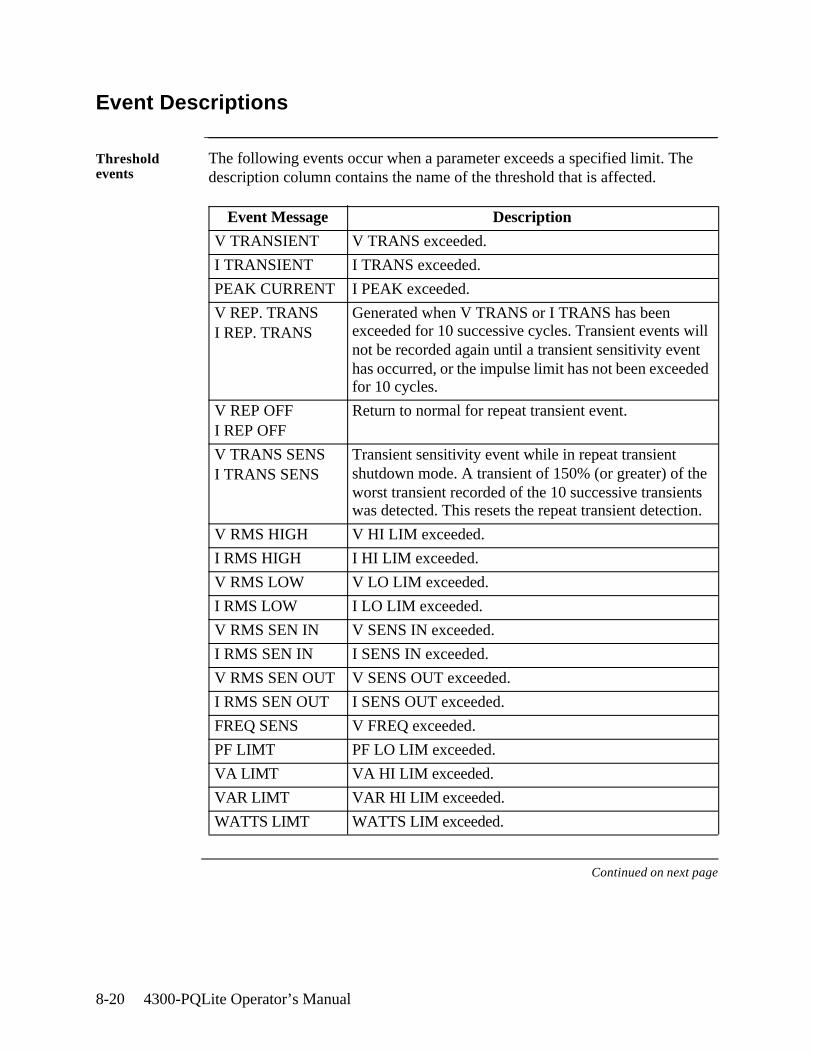
8-20 4300-PQLite Operator’s Manual
Event Descriptions
Threshold events
The following events occur when a parameter exceeds a specified limit. The description column contains the name of the threshold that is affected.
Continued on next page
Event Message Description
V TRANSIENT V TRANS exceeded.
I TRANSIENT I TRANS exceeded.
PEAK CURRENT I PEAK exceeded.
V REP. TRANSI REP. TRANS
Generated when V TRANS or I TRANS has been exceeded for 10 successive cycles. Transient events will not be recorded again until a transient sensitivity event has occurred, or the impulse limit has not been exceeded for 10 cycles.
V REP OFFI REP OFF
Return to normal for repeat transient event.
V TRANS SENSI TRANS SENS
Transient sensitivity event while in repeat transient shutdown mode. A transient of 150% (or greater) of the worst transient recorded of the 10 successive transients was detected. This resets the repeat transient detection.
V RMS HIGH V HI LIM exceeded.
I RMS HIGH I HI LIM exceeded.
V RMS LOW V LO LIM exceeded.
I RMS LOW I LO LIM exceeded.
V RMS SEN IN V SENS IN exceeded.
I RMS SEN IN I SENS IN exceeded.
V RMS SEN OUT V SENS OUT exceeded.
I RMS SEN OUT I SENS OUT exceeded.
FREQ SENS V FREQ exceeded.
PF LIMT PF LO LIM exceeded.
VA LIMT VA HI LIM exceeded.
VAR LIMT VAR HI LIM exceeded.
WATTS LIMT WATTS LIM exceeded.
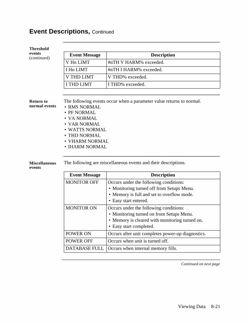
Viewing Data 8-21
Event Descriptions, Continued
Threshold events (continued)
Return to normal events
The following events occur when a parameter value returns to normal.• RMS NORMAL• PF NORMAL• VA NORMAL• VAR NORMAL• WATTS NORMAL• THD NORMAL• VHARM NORMAL• IHARM NORMAL
Miscellaneous events
The following are miscellaneous events and their descriptions.
Continued on next page
Event Message Description
V Hn LIMT #nTH V HARM% exceeded.
I Hn LIMT #nTH I HARM% exceeded.
V THD LIMT V THD% exceeded.
I THD LIMT I THD% exceeded.
Event Message Description
MONITOR OFF Occurs under the following conditions:• Monitoring turned off from Setups Menu.• Memory is full and set to overflow mode.• Easy start entered.
MONITOR ON Occurs under the following conditions:• Monitoring turned on from Setups Menu.• Memory is cleared with monitoring turned on.• Easy start completed.
POWER ON Occurs after unit completes power-up diagnostics.
POWER OFF Occurs when unit is turned off.
DATABASE FULL Occurs when internal memory fills.
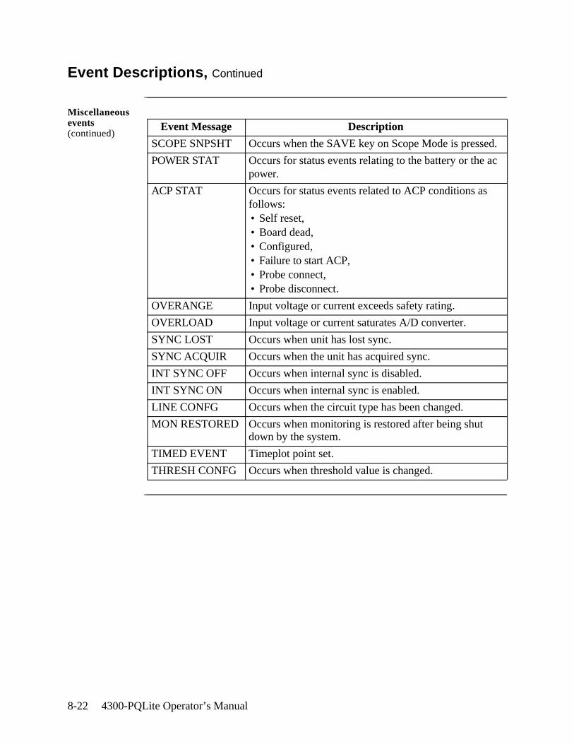
8-22 4300-PQLite Operator’s Manual
Event Descriptions, Continued
Miscellaneous events (continued)
Event Message Description
SCOPE SNPSHT Occurs when the SAVE key on Scope Mode is pressed.
POWER STAT Occurs for status events relating to the battery or the ac power.
ACP STAT Occurs for status events related to ACP conditions as follows:• Self reset,• Board dead,• Configured,• Failure to start ACP,• Probe connect,• Probe disconnect.
OVERANGE Input voltage or current exceeds safety rating.
OVERLOAD Input voltage or current saturates A/D converter.
SYNC LOST Occurs when unit has lost sync.
SYNC ACQUIR Occurs when the unit has acquired sync.
INT SYNC OFF Occurs when internal sync is disabled.
INT SYNC ON Occurs when internal sync is enabled.
LINE CONFG Occurs when the circuit type has been changed.
MON RESTORED Occurs when monitoring is restored after being shut down by the system.
TIMED EVENT Timeplot point set.
THRESH CONFG Occurs when threshold value is changed.
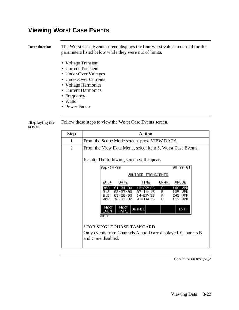
Viewing Data 8-23
Viewing Worst Case Events
Introduction The Worst Case Events screen displays the four worst values recorded for the parameters listed below while they were out of limits.
• Voltage Transient• Current Transient• Under/Over Voltages• Under/Over Currents• Voltage Harmonics• Current Harmonics• Frequency• Watts• Power Factor
Displaying the screen
Follow these steps to view the Worst Case Events screen.
Continued on next page
Step Action
1 From the Scope Mode screen, press VIEW DATA.
2 From the View Data Menu, select item 3, Worst Case Events.
Result: The following screen will appear.
! FOR SINGLE PHASE TASKCARDOnly events from Channels A and D are displayed. Channels B and C are disabled.
4300-92
8-24 4300-PQLite Operator’s Manual
Viewing Worst Case Events, Continued
Function keys The following table provides a description of the functions keys for the Worst Case Events screen.
Key Function
NEXT EVENT Moves the highlight.
NEXT TYPE Displays the worst case events for the next parameter type according to the list on the previous page.
NOTE: If there are no events for a given parameter, the message “No Worst Case Events” is displayed.
DETAIL Displays details of the highlighted event. See page 8-26 for a description of the Event Details screen.
EXIT Returns to the View Data Menu.
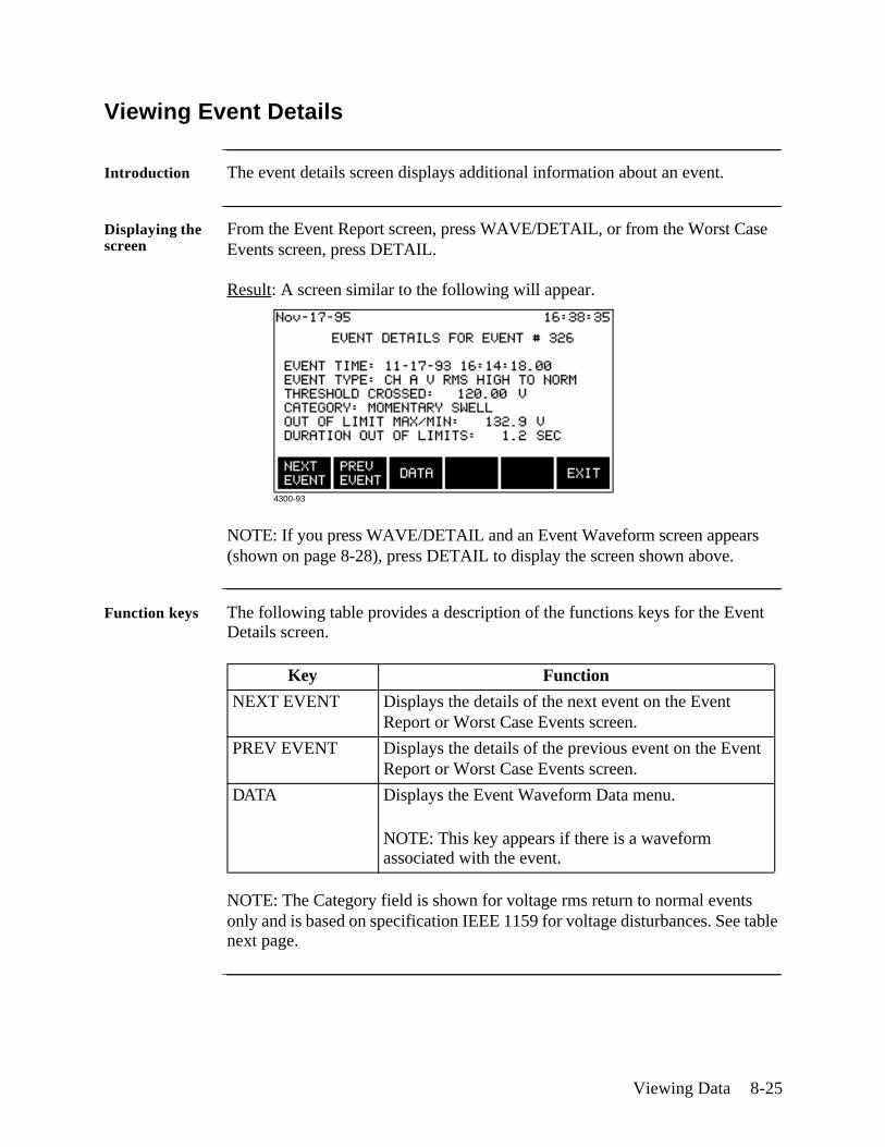
Viewing Data 8-25
Viewing Event Details
Introduction The event details screen displays additional information about an event.
Displaying the screen
From the Event Report screen, press WAVE/DETAIL, or from the Worst Case Events screen, press DETAIL.
Result: A screen similar to the following will appear.
NOTE: If you press WAVE/DETAIL and an Event Waveform screen appears (shown on page 8-28), press DETAIL to display the screen shown above.
Function keys The following table provides a description of the functions keys for the Event Details screen.
NOTE: The Category field is shown for voltage rms return to normal events only and is based on specification IEEE 1159 for voltage disturbances. See table next page.
Key Function
NEXT EVENT Displays the details of the next event on the Event Report or Worst Case Events screen.
PREV EVENT Displays the details of the previous event on the Event Report or Worst Case Events screen.
DATA Displays the Event Waveform Data menu.
NOTE: This key appears if there is a waveform associated with the event.
4300-93
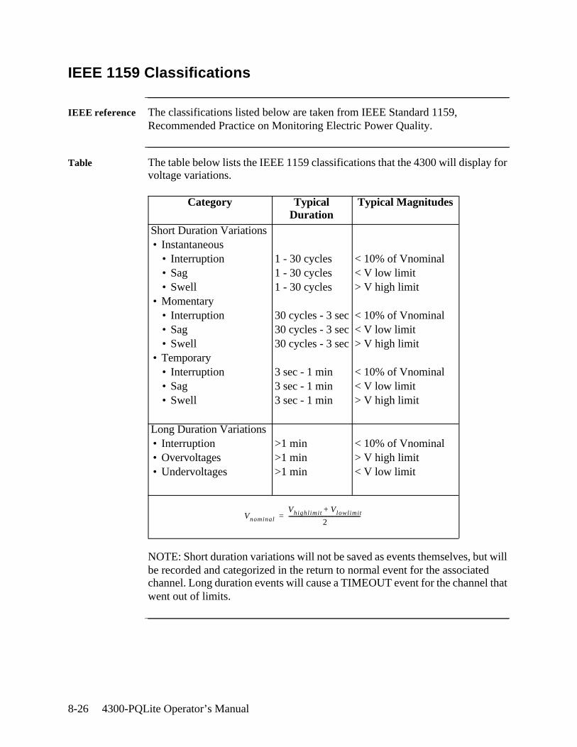
8-26 4300-PQLite Operator’s Manual
IEEE 1159 Classifications
IEEE reference The classifications listed below are taken from IEEE Standard 1159, Recommended Practice on Monitoring Electric Power Quality.
Table The table below lists the IEEE 1159 classifications that the 4300 will display for voltage variations.
NOTE: Short duration variations will not be saved as events themselves, but will be recorded and categorized in the return to normal event for the associated channel. Long duration events will cause a TIMEOUT event for the channel that went out of limits.
Category Typical Duration
Typical Magnitudes
Short Duration Variations• Instantaneous
• Interruption• Sag• Swell
• Momentary• Interruption• Sag• Swell
• Temporary• Interruption• Sag• Swell
1 - 30 cycles1 - 30 cycles1 - 30 cycles
30 cycles - 3 sec30 cycles - 3 sec30 cycles - 3 sec
3 sec - 1 min3 sec - 1 min3 sec - 1 min
< 10% of Vnominal< V low limit> V high limit
< 10% of Vnominal< V low limit> V high limit
< 10% of Vnominal< V low limit> V high limit
Long Duration Variations• Interruption• Overvoltages• Undervoltages
>1 min>1 min>1 min
< 10% of Vnominal> V high limit< V low limit
Vnominal
Vhighlimit Vlowlimit+
2---------------------------------------------------=
Viewing Data 8-27
Section D
Event Waveforms
Overview
In this section The following topics are covered in this section.
Topic See Page
Viewing Event Waveforms 8-28
Analyzing Event Waveforms 8-30
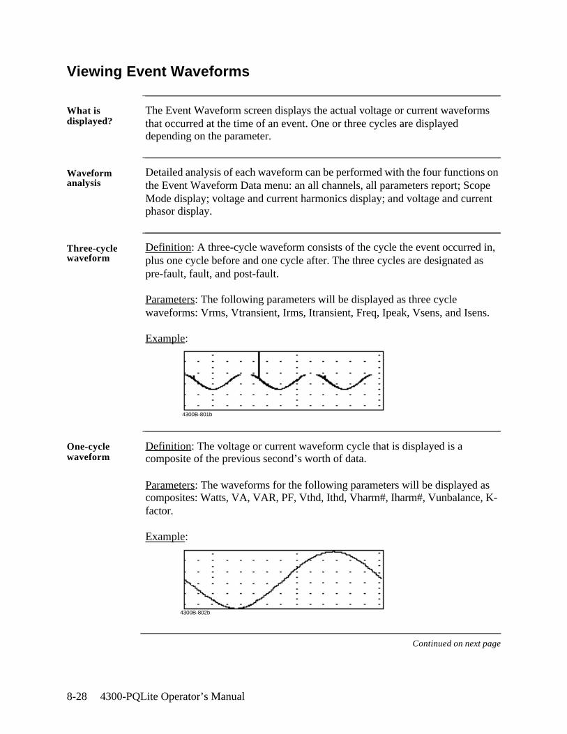
8-28 4300-PQLite Operator’s Manual
Viewing Event Waveforms
What is displayed?
The Event Waveform screen displays the actual voltage or current waveforms that occurred at the time of an event. One or three cycles are displayed depending on the parameter.
Waveform analysis
Detailed analysis of each waveform can be performed with the four functions on the Event Waveform Data menu: an all channels, all parameters report; Scope Mode display; voltage and current harmonics display; and voltage and current phasor display.
Three-cycle waveform
Definition: A three-cycle waveform consists of the cycle the event occurred in, plus one cycle before and one cycle after. The three cycles are designated as pre-fault, fault, and post-fault.
Parameters: The following parameters will be displayed as three cycle waveforms: Vrms, Vtransient, Irms, Itransient, Freq, Ipeak, Vsens, and Isens.
Example:
One-cycle waveform
Definition: The voltage or current waveform cycle that is displayed is a composite of the previous second’s worth of data.
Parameters: The waveforms for the following parameters will be displayed as composites: Watts, VA, VAR, PF, Vthd, Ithd, Vharm#, Iharm#, Vunbalance, K-factor.
Example:
Continued on next page
4300B-801b
4300B-802b
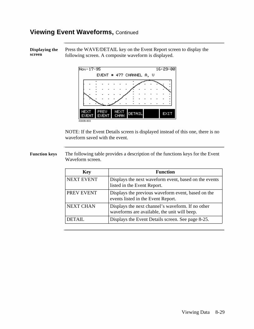
Viewing Data 8-29
Viewing Event Waveforms, Continued
Displaying the screen
Press the WAVE/DETAIL key on the Event Report screen to display the following screen. A composite waveform is displayed.
NOTE: If the Event Details screen is displayed instead of this one, there is no waveform saved with the event.
Function keys The following table provides a description of the functions keys for the Event Waveform screen.
Key Function
NEXT EVENT Displays the next waveform event, based on the events listed in the Event Report.
PREV EVENT Displays the previous waveform event, based on the events listed in the Event Report.
NEXT CHAN Displays the next channel’s waveform. If no other waveforms are available, the unit will beep.
DETAIL Displays the Event Details screen. See page 8-25.
4300B-803
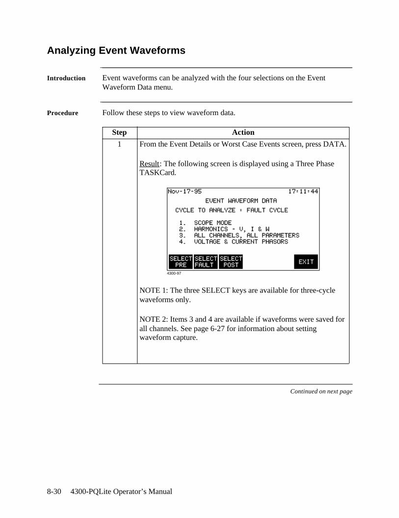
8-30 4300-PQLite Operator’s Manual
Analyzing Event Waveforms
Introduction Event waveforms can be analyzed with the four selections on the Event Waveform Data menu.
Procedure Follow these steps to view waveform data.
Continued on next page
Step Action
1 From the Event Details or Worst Case Events screen, press DATA.
Result: The following screen is displayed using a Three Phase TASKCard.
NOTE 1: The three SELECT keys are available for three-cycle waveforms only.
NOTE 2: Items 3 and 4 are available if waveforms were saved for all channels. See page 6-27 for information about setting waveform capture.
4300-97
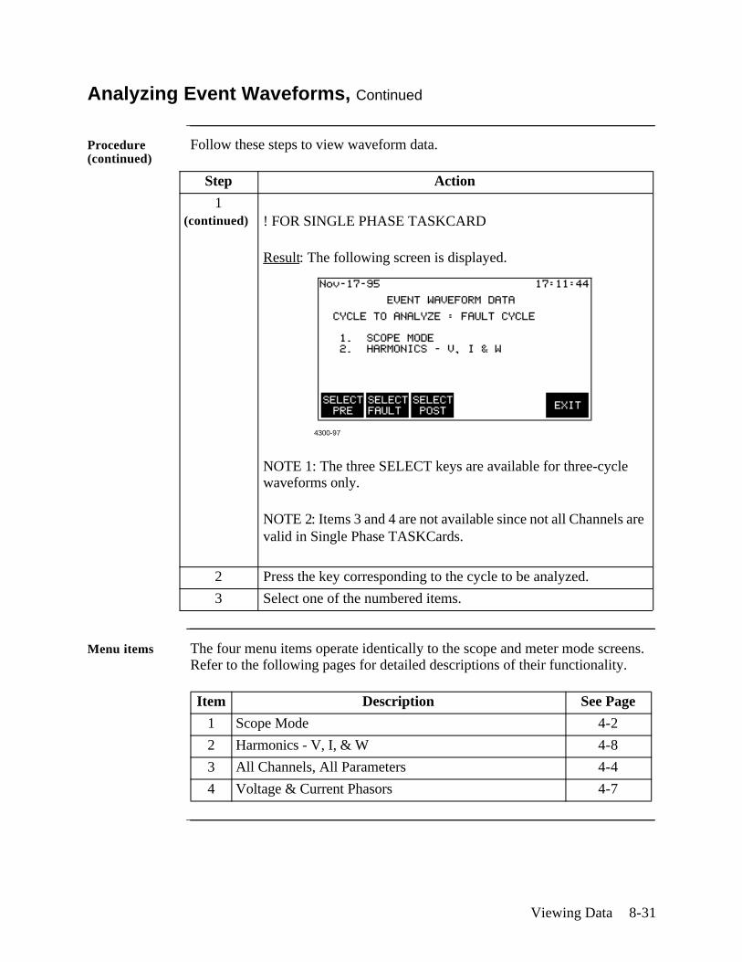
Viewing Data 8-31
Analyzing Event Waveforms, Continued
Procedure (continued)
Follow these steps to view waveform data.
Menu items The four menu items operate identically to the scope and meter mode screens. Refer to the following pages for detailed descriptions of their functionality.
Step Action
1(continued) ! FOR SINGLE PHASE TASKCARD
Result: The following screen is displayed.
NOTE 1: The three SELECT keys are available for three-cycle waveforms only.
NOTE 2: Items 3 and 4 are not available since not all Channels are valid in Single Phase TASKCards.
2 Press the key corresponding to the cycle to be analyzed.
3 Select one of the numbered items.
Item Description See Page
1 Scope Mode 4-2
2 Harmonics - V, I, & W 4-8
3 All Channels, All Parameters 4-4
4 Voltage & Current Phasors 4-7
4300-97
8-32 4300-PQLite Operator’s Manual
Section E
Downloading Events from 4300 to a Computer
Overview
In this section The following topics are covered in this section.
Topic See Page
Hardware Requirements 8-33
Software Requirements 8-34
Connection Guidelines 8-36
Downloading Events 8-37

Viewing Data 8-33
Hardware Requirements
Equipment required
To download events from the PP4300 through the optical port, you must have the following equipment available:
• Personal computer or laptop computer with Windows operating system and a serial communications port.
• Isolated Communications Module (P/N PP4300-RS232)
The ISOLATED COMMUNICATIONS MODULE is a communications media that is used to transfer data (EVENTS) from the 4300 to a personal computer or a laptop. It consists of two parts, the fiber optic cable that goes into the optical port of the 4300, and the 4300RS232 adapter that is terminated by a 9-pin RS232 connector. The RS232 interface is supported using the PC standard serial ports COM1 to COM4.
8-34 4300-PQLite Operator’s Manual
Software Requirements
DRAN-LINKTM application
To download events from the PP4300 through the optical port, you must have the following program available: DRAN-LINKTM 4300 V1.0 communications utility software.
DRAN-LINK 4300 is an easy-to-use Windows application which permits transferring (downloading) stored data from the 4300 to a disk file. Using DRAN-LINK 4300, the datafile can be seamlessly transferred to a viewer such as DRANVIEW. DRAN-LINK 4300 shares a common user interface with other members of the DRAN-LINK family of applications available from Dranetz-BMI. In view of this, menu functions which are not applicable to a particular DRAN-LINK software version are disabled.
DRAN-LINK 4300 communicates with the 4300 via a standard RS-232 serial port on the host computer using the Isolated Communications Module. DRAN-LINK 4300 uses a request/response block transfer protocol with error checking to assure maximum data integrity.
Once data transfer has begun, you can work with other Windows applications while DRAN-LINK 4300 runs in the background. Data transfer rate is at 19200 bits per second.
DRAN-VIEW®
applicationDRAN-VIEW® is a Windows 3.1/Windows 95 and Windows NT compatible program that is used to access and retrieve data from data files on a memory card (requires PCMCIA slot or memory card reader) or from other disk media compatible with MS-Windows operating system. Following are the features and highlights of DRAN-VIEW® application:
• Direct interface with DRAN-LINK communications software• Two-pane browser (timeplots and waveforms simultaneously)• Multiple ZOOM levels (up to 15 times)• Advanced Harmonic analysis (DFT/FFT) featuring phasor diagrams and
flexible data presentation• Toolbar and Button support• Drop-down Events list• Multi-parameter time plots• Time measurement tool (delta measurement)• Saves data to .DNV (DRAN-VIEW compressed format) or converts to ASCII• Status bar displays time, date and selected pane parameters• Accelerator keys and right mouse button support• Cut and paste to other applications• Email .DNV data files directly from DRAN-VIEW
Viewing Data 8-35
Software Requirements, Continued
DRAN-VIEW® application (continued)
DRAN-VIEW® is a tool for viewing data on a computer from the following Dranetz-BMI analyzers and TASKCards:• Power Platform® PP4300 with TASKCard PQLite and TASKCard 808• Power Platform® PP1 with TASKCard PQPlus and TASKCard Flicker• 658 PQ Analyzer• DRAN-LOGGER® DL1, DL1-T
DRAN-VIEW® application packages include DRAN-VIEW Pro and DRAN-VIEW Report Writer.
The following features are available only in DRAN-VIEW Pro:• File Append• Harmonic and 3D timeplots• Statistics Table with timeplots containing min, max, weighted median,
standard deviation, 5%, 95%, and 99% figures.• Report Writer (though the standard version of DRAN-VIEW may be
upgraded to include Report Writer by installing a Report Writer Driver provided on a separate diskette)
For more information about the DRAN-LINKTM and DRAN-VIEW® product lines, contact Dranetz Customer Service at (732) 287-3680 or 1-800-DRANTEC.
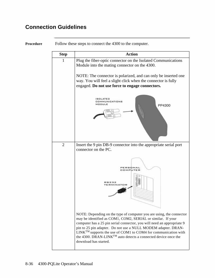
8-36 4300-PQLite Operator’s Manual
Connection Guidelines
Procedure Follow these steps to connect the 4300 to the computer.
Step Action
1 Plug the fiber-optic connector on the Isolated Communications Module into the mating connector on the 4300.
NOTE: The connector is polarized, and can only be inserted one way. You will feel a slight click when the connector is fully engaged. Do not use force to engage connectors.
2 Insert the 9 pin DB-9 connector into the appropriate serial port connector on the PC.
NOTE: Depending on the type of computer you are using, the connector may be identified as COM1, COM2, SERIAL or similar. If your computer has a 25 pin serial connector, you will need an appropriate 9 pin to 25 pin adapter. Do not use a NULL MODEM adapter. DRAN-LINKTM supports the use of COM1 to COM4 for communication with the 4300. DRAN-LINKTM auto detects a connected device once the download has started.
PP4300
Viewing Data 8-37
Downloading Events
With DRAN-LINKTM 4300 you can choose to download data from the PP4300 Internal Memory or from a Memory Card (if one is installed).
Downloading Events from Internal Memory
Download Internal Memory command (Communicate Menu / Link)
DRAN-LINKTM 4300 will prompt for a file in which to save the download data using a File Save dialog. Once a filename has been specified, DRAN-LINK 4300 attempts to establish communication with the 4300, and if successful, begins transferring data to the file.
DRAN-LINK 4300 displays a progress indicator window during the transfer operation. The window has a CANCEL button to permit termination of data transfer.
Downloading data from the Internal memory of the 4300 takes about 3 minutes.
Downloading Events from Memory Card
Download Memory Card command (Communicate Menu / Link)
DRAN-LINKTM 4300 will prompt for a file in which to save the download data using a File Save dialog. Once a filename has been specified, DRAN-LINK 4300 attempts to establish communication with the 4300, and if successful, begins transferring data to the file.
DRAN-LINK 4300 displays a progress indicator window during the transfer operation. The window has a CANCEL button to permit termination of data transfer.
Downloading the data from the External memory of the 4300 takes about 20 minutes for a typical 2MB memory card.
DRAN-LINK 4300 produces a message display to signal the end of the transfer operation. DRAN-LINK 4300 also produces a message display if the 4300 reports an error or the transfer operation is aborted at the 4300.
NOTE: Do not attempt to save the datafile on a floppy disk. The amount of data that is transferred from the memory card will exceed the capacity of a floppy disk and produce a disk full error during the transfer.
It is recommended to upgrade your TASKCard PQLite version to at least V3.8 to ensure a faster and more reliable download.

8-38 4300-PQLite Operator’s Manual
Optional Accessories A-1
Appendix A
Optional Accessories
Overview
Introduction This appendix is divided into two sections.
Section A provides a general listing of the various optional accessories available for use with the PP4300. It features basic descriptions of some of the optional accessories.
Section B provides detailed discussion on the CompactFlash memory card - the optional accessory that replaces the old model memory card. Discussion includes upgrade features as well as instructions on how to use the CompactFlash with the PP4300 and with TASKCard PQLite version 4.2 or higher.
In this appendix This Appendix is divided into two Sections.
Section Title See Pages
A Accessory List and Descriptions A-3
B CompactFlash Card A-9
A-2 4300-PQLite Operator’s Manual
Section A
Accessory List and Descriptions
Overview
Introduction This Section lists the optional accessories that are available for the 4300. Descriptions for some of the accessories are given after the list.
In this section The following topics are covered in this section.
Topic See Page
Optional Accessories List A-3
Optional Accessories Descriptions A-5
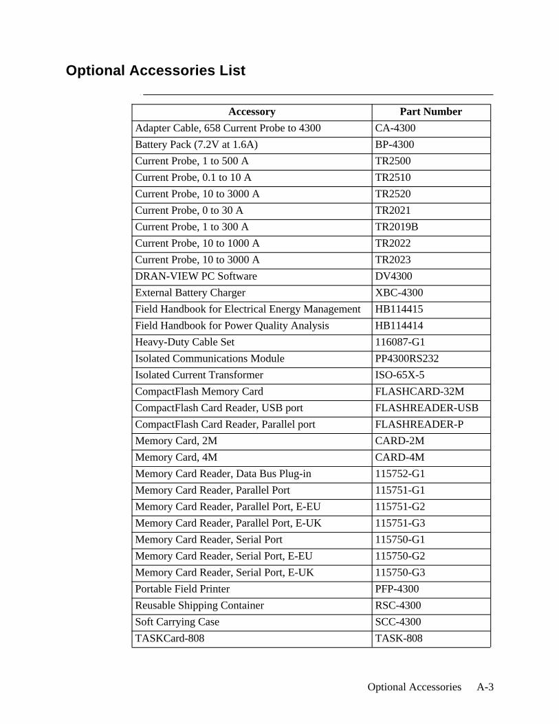
Optional Accessories A-3
Optional Accessories List
Accessory Part Number
Adapter Cable, 658 Current Probe to 4300 CA-4300
Battery Pack (7.2V at 1.6A) BP-4300
Current Probe, 1 to 500 A TR2500
Current Probe, 0.1 to 10 A TR2510
Current Probe, 10 to 3000 A TR2520
Current Probe, 0 to 30 A TR2021
Current Probe, 1 to 300 A TR2019B
Current Probe, 10 to 1000 A TR2022
Current Probe, 10 to 3000 A TR2023
DRAN-VIEW PC Software DV4300
External Battery Charger XBC-4300
Field Handbook for Electrical Energy Management HB114415
Field Handbook for Power Quality Analysis HB114414
Heavy-Duty Cable Set 116087-G1
Isolated Communications Module PP4300RS232
Isolated Current Transformer ISO-65X-5
CompactFlash Memory Card FLASHCARD-32M
CompactFlash Card Reader, USB port FLASHREADER-USB
CompactFlash Card Reader, Parallel port FLASHREADER-P
Memory Card, 2M CARD-2M
Memory Card, 4M CARD-4M
Memory Card Reader, Data Bus Plug-in 115752-G1
Memory Card Reader, Parallel Port 115751-G1
Memory Card Reader, Parallel Port, E-EU 115751-G2
Memory Card Reader, Parallel Port, E-UK 115751-G3
Memory Card Reader, Serial Port 115750-G1
Memory Card Reader, Serial Port, E-EU 115750-G2
Memory Card Reader, Serial Port, E-UK 115750-G3
Portable Field Printer PFP-4300
Reusable Shipping Container RSC-4300
Soft Carrying Case SCC-4300
TASKCard-808 TASK-808
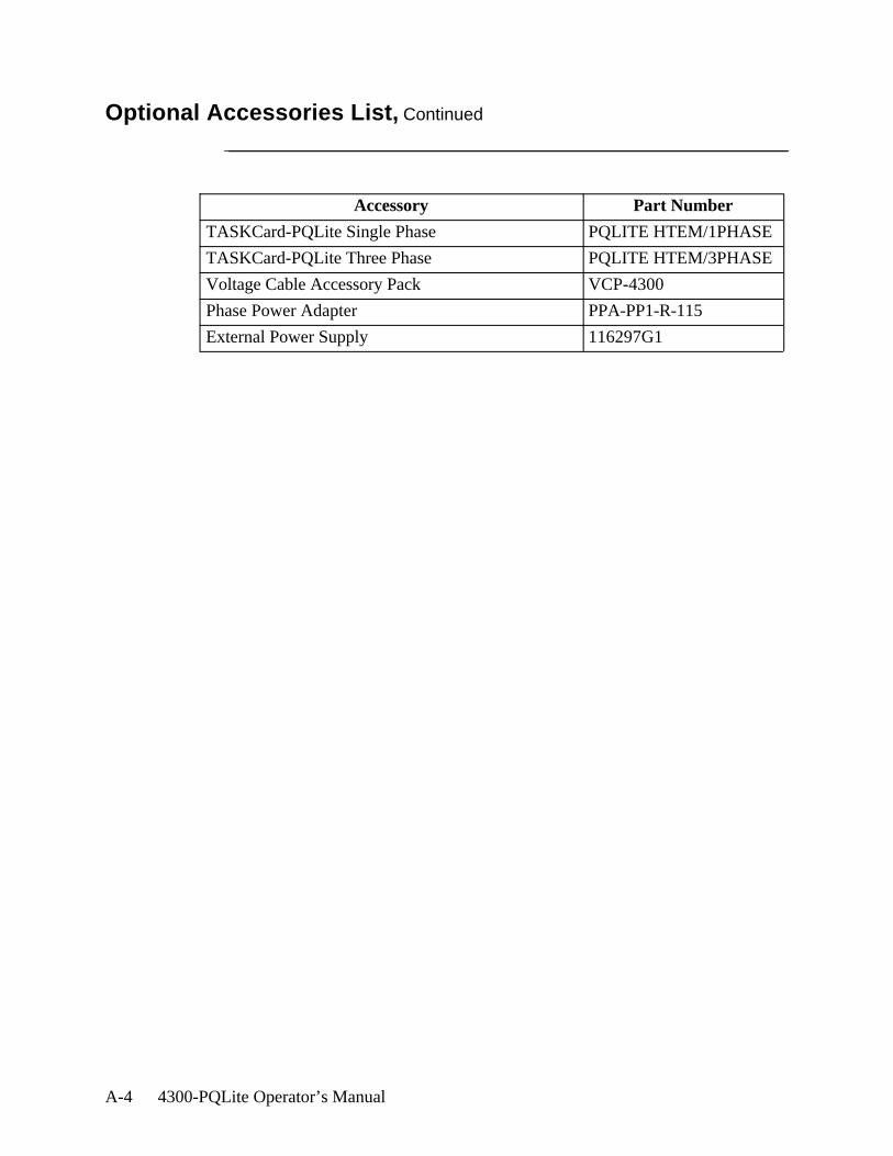
A-4 4300-PQLite Operator’s Manual
Optional Accessories List, Continued
Accessory Part Number
TASKCard-PQLite Single Phase PQLITE HTEM/1PHASE
TASKCard-PQLite Three Phase PQLITE HTEM/3PHASE
Voltage Cable Accessory Pack VCP-4300
Phase Power Adapter PPA-PP1-R-115
External Power Supply 116297G1
Optional Accessories A-5
Optional Accessories Descriptions
Adapter cable, 658 current probes to 4300
This cable allows connection of current probes made for the Dranetz Model 658 to the 4300 current input jacks. See illustration in Chapter 3.
Current probes Several Dranetz current probes can be used with the 4300: models TR2500, TR2510, TR2520, TR2019B, TR2021, TR2022, TR2023. Typical current probes are illustrated in Chapter 3.
TR2500, TR2510, TR2520: These models will measure rms currents from 1 to 500 A, 0.1 to 10 A, 10 to 3000 A, respectively. They plug directly into any of the current inputs on the rear panel.
TR2021, TR2019B, TR2022, TR2023: These four probes are made for the Dranetz model 658 but can be used with the 4300 by using an adapter cable (part number 116002-G1). They can measure rms currents in ranges of 0 to 30 A, 1 to 300 A, 10 to 1000 A, and 10 to 3000 A, respectively, and are needed to accurately measure transients.
Field Handbook for Electrical Energy Management
This reference handbook provides a comprehensive guide for information related to conducting a thorough energy audit, power distribution analysis, and methods of remedying inefficiencies of energy management.
Field Handbook for Power Quality Analysis
This handbook is divided into six sections containing step-by-step instructions for discovering and solving complex power quality problems. Example waveforms and case studies are included.
External Battery Charger
The XBC-4300 charges a battery pack while the 4300 is in use.
Heavy duty cable set
Consists of: one red, one yellow, one blue, and five black measurement cables, each eight feet long, and two blue or black jumper cables, each one foot long.
A-6 4300-PQLite Operator’s Manual
Optional Accessories Descriptions, Continued
Isolated Communi-cations Module
An optically isolated device using infrared light to transfer text and graphics to a PC or printer. Connects the optical serial port on the 4300 to a standard RS232 serial port. Can be connected to a PC using DRAN-LINKTM and DRAN-VIEW® software or to an EPSON graphics compatible printer.
Isolated Current Transformer
Allows the connection of other industry-standard 5 A output current transformers to Dranetz equipment.
CompactFlash Memory Card (new model)
TASKCard PQLite V4.2 or higher support the use of CompactFlash cards. CompactFlash has a more robust data handling and storage capability than the old model memory cards. It is available in sizes ranging from 8MB to 32MB. See page A-9 for details.
Optional CompactFlash card readers
Two types of card readers are available for easy data manipulation and data transfer from the CompactFlash card to the computer: USB port (FLASHREADER-USB) or Parallel port (FLASHREADER-P). For pricing and availability, contact Dranetz Customer Service department at 732-287-3680.
Memory card (old model)
Several sizes of memory cards are available, from 2MB to 4MB. The memory card is read by the optional memory card reader.
Memory card readers
Three types of memory card readers are available as options. Each reader provides a different means of communications with an IBM compatible computer. The three types are: RS232 serial port, parallel port, and data bus plug-in. Memory card readers for the serial port and the parallel port are further modified and made available in Standard, European (EU) and UK versions.
Portable Field Printer
Used for printing 4300 screens. Connects to the 4300 using the Isolated Communications Module.
Reusable Shipping Container
Lockable, high-impact plastic case with foam insulation for protecting the 4300 during shipping.
Soft Carrying Case
Heavy-duty, padded, nylon carrying case. Includes pockets for cable set, current probes, and other accessories.
Optional Accessories A-7
Optional Accessories Descriptions, Continued
TASKCard 808 This TASKCard changes the 4300 to a power quantity monitor so that it measures, records, and displays electric power parameters such as demand, energy, and power factor. This can help you cut costs by identifying equipment that is operating inefficiently.
TASKCard PQLite
The PQLite TASKCard is available in two model configurations:
PQLite HTEM 1 Phase (Single Phase): This TASKCard turns the 4300 into a power quality monitor that records sags, swells, interruptions, transients, and power. It provides full power quality and harmonics monitoring for two (2) active channels (V/I) and neutral (V/I). From the four A, B, C and D Channel connectors found in the 4300 instrument, only Channels A and D are valid when using Single Phase TASKCards. Channels B and C are masked and set to OFF by default. The Single Phase TASKCard can measure, record and analyze up to sixteen (16) power quality parameters. It has memory card functions that allow data to be saved to an optional memory card manually, automatically, or both. The DRANETZ-BMI TASKCard system allows users to easily and cost-effectively upgrade the 4300 instrument by simply switching from a Single Phase to a Three Phase TASKCard.
PQLite HTEM 3 Phase (Three Phase): This TASKCard turns the 4300 into a power quality monitor that records sags, swells, interruptions, power, harmonics and transients. It incorporates all previous individual TASKCard PQLite/H-T-M (harmonics, transient capture, memory) functionalities, plus demand and energy recording. The Three Phase TASKCard provides for eight (8) channel monitoring (4V/4I) of power quality, harmonics and energy. All four A, B, C and D Channel connectors are valid and enabled when using Three Phase TASKCards. It also has memory card functions, which allow data to be saved to an optional memory card manually, automatically, or both.
Voltage Cable Accessory Pack
Contains one, single phase measurement cable which allows measurement of a single phase circuit using a standard 115 Vrms AC outlet, and four jumper cables which allow easy interconnection of the measurement cables.

A-8 4300-PQLite Operator’s Manual
Optional Accessories Descriptions, Continued
Ordering information
To order accessories contact Dranetz Customer Service Department at:
Dranetz-BMI Tel: (732) 287-36801000 New Durham Road Tel: 1-800-372-6832Edison, NJ 08818-4019 USA FAX: (732) 248-1834Attention: Customer Service www.dranetz-bmi.com
Optional Accessories A-9
Section B
CompactFlash Card
Overview
Introduction This Section focuses on the optional accessory that can be used to replace old model SRAM memory cards - the CompactFlash cards. CompactFlash can be used with TASKCard PQLite V4.2 or higher. Upgrade features as well as instructions on how to use the card with PP4300 and TASKCard PQLite V4.2 are discussed.
In this section The following topics are covered in this section.
Topic See Page
CompactFlash Card Power Features A-10
Using CompactFlash Card with the PP4300 A-11
Using Compact Flash Card with TASKCard PQLite V4.2 or higher
A-12

A-10 4300-PQLite Operator’s Manual
CompactFlash Card Power Features
Key Features The sleek, versatile CompactFlash Card replaces the optional SRAM memory data card and is now available for use with the PP4300. TASKCard PQLite V4.2 or higher support the use of CompactFlash cards. This new model memory card has a more robust data handling and storage capability and has the following key features:
• Increased data storage size - from 8MB to 32 MB• Allows auto transfer files of up to 8MB• Allows storage of multiple data files• Improved speed performance during formatting and file creation• Reduced cost
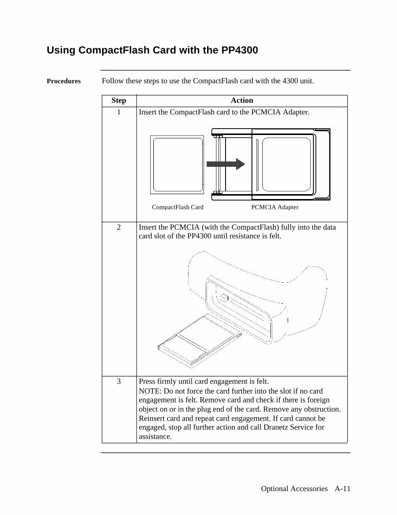
Optional Accessories A-11
Using CompactFlash Card with the PP4300
Procedures Follow these steps to use the CompactFlash card with the 4300 unit.
Step Action
1 Insert the CompactFlash card to the PCMCIA Adapter.
2 Insert the PCMCIA (with the CompactFlash) fully into the data card slot of the PP4300 until resistance is felt.
3 Press firmly until card engagement is felt.NOTE: Do not force the card further into the slot if no card engagement is felt. Remove card and check if there is foreign object on or in the plug end of the card. Remove any obstruction. Reinsert card and repeat card engagement. If card cannot be engaged, stop all further action and call Dranetz Service for assistance.
CompactFlash Card PCMCIA Adapter
A-12 4300-PQLite Operator’s Manual
Using CompactFlash Card with TASKCard PQLite V4.2 or higher
Auto-transfer functions
TASKCard PQLite V4.2 or higher treats the CompactFlash card like a floppy disk storing files in DOS format. For successful card data transfer, keep the following points in mind:
• PQLite V4.2 supports a maximum DOS directory size of 32MB. If you use up more than 32MB, the card will be formatted to use up to 32MB space and will render the remaining space unusable.
• The maximum size for auto-transfer file has increased from 4MB to 8MB. CompactFlash cards allow you to store multiple auto-transfer files in one card. The Site ID will be used as the filename (i.e. if the site name is SITE_1, the filename will be SITE_1.MDB). To create auto-transfer files, see Automatically Saving Data to a Memory Card on page 7-3.
• PQLite V4.2 does not support file fragmentation. When creating an auto-transfer file, it will look for a contiguous block of 8MB and use that size block for data storage. If the remaining space is less than 8MB, it will use the largest block it can find that is greater than 1MB. If you use a block less than 8MB, the card may be fragmented and you may not get optimum results or lose data. Deleting files from the memory card on the 4300 is NOT RECOMMENDED. Whenever possible, reformat the card using the PP4300 when there is no more space available to begin new data storage.
Manually saving data files
Events and setups can be written to a memory card. The card must be formatted before it can be written to.
To manually save a data or setup file, see Manually Saving Data to a Memory Card on page 7-5.
Appending data files
The File Append feature is available only using DRAN-VIEW Pro.
The DRAN-VIEW Pro package allows several files to be merged into one DRAN-VIEW DNV file. Use this command to add another database file (DNV, MDB or EVT) to the active document. After the APPEND process, the document will contain data from two individual data files in a single file. Another APPEND can be issued to add data from a third data file into the
Continued on next page
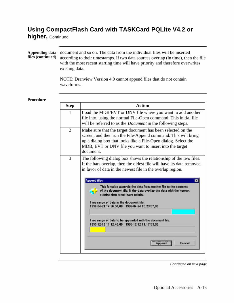
Optional Accessories A-13
Using CompactFlash Card with TASKCard PQLite V4.2 or higher, Continued
Appending data files (continued)
document and so on. The data from the individual files will be inserted according to their timestamps. If two data sources overlap (in time), then the file with the most recent starting time will have priority and therefore overwrites existing data.
NOTE: Dranview Version 4.0 cannot append files that do not contain waveforms.
Procedure
Continued on next page
Step Action
1 Load the MDB/EVT or DNV file where you want to add another file into, using the normal File-Open command. This initial file will be referred to as the Document in the following steps.
2 Make sure that the target document has been selected on the screen, and then run the File-Append command. This will bring up a dialog box that looks like a File-Open dialog. Select the MDB, EVT or DNV file you want to insert into the target document.
3 The following dialog box shows the relationship of the two files. If the bars overlap, then the oldest file will have its data removed in favor of data in the newest file in the overlap region.
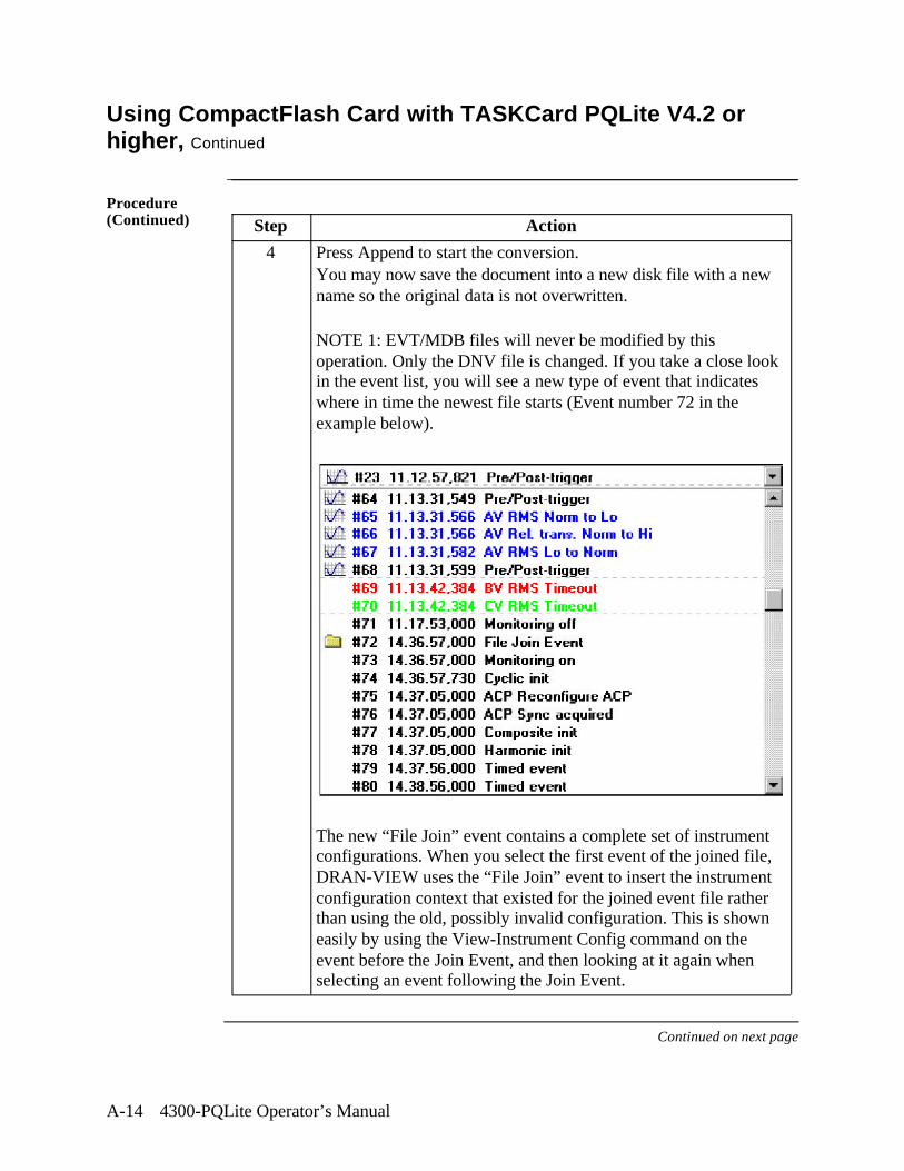
A-14 4300-PQLite Operator’s Manual
Using CompactFlash Card with TASKCard PQLite V4.2 or higher, Continued
Procedure (Continued)
Continued on next page
Step Action
4 Press Append to start the conversion.You may now save the document into a new disk file with a new name so the original data is not overwritten.
NOTE 1: EVT/MDB files will never be modified by this operation. Only the DNV file is changed. If you take a close look in the event list, you will see a new type of event that indicates where in time the newest file starts (Event number 72 in the example below).
The new “File Join” event contains a complete set of instrument configurations. When you select the first event of the joined file, DRAN-VIEW uses the “File Join” event to insert the instrument configuration context that existed for the joined event file rather than using the old, possibly invalid configuration. This is shown easily by using the View-Instrument Config command on the event before the Join Event, and then looking at it again when selecting an event following the Join Event.
Optional Accessories A-15
Using CompactFlash Card with TASKCard PQLite V4.2 or higher, Continued
Procedure (Continued)
For information on the DRAN-VIEW® and DRAN-VIEW Pro software package, see Chapter 8 Viewing Data: Downloading Events from 4300 to a Computer - Software Requirements on page 8-34.
Step Action
4 (continued)
As an example, the Site Information String (&s) that you may include in your chart footers may change when DRAN-VIEW comes to the “File Join” event. This demonstrates that the “Join Event” contains both the instrument and the DRAN-VIEW setups of the joined file.
NOTE 2: This command is provided primarily as a means to join (concatenate) and merge databases of similar content and origin. There will be some data loss in the older file in regions of data overlap. Some caution is indicated to help avoid unexpected or nonsense results. For instance, combining a 658 with a PP1 PQPlus database is not recommended. This command is best used when appending files measured with the same instrument and on the same measuring point. At minimum, append only those files that have the same line frequency. There is no theoretical limitation on how many files may be appended. There is however a theoretical limitation of 32000 events in a DNV file. Before reaching these 32000 events, you will find that DRAN-VIEW starts to become slower and slower due to the huge amount of data. The practical limitation depends on the performance of your computer.

A-16 4300-PQLite Operator’s Manual
Technical Specifications B-1
Appendix B
Technical Specifications
Overview
In this appendix The following specifications are covered in this appendix.
Topic See Page
General B-2
Interfaces B-3
Measured Parameters B-4
Computed Parameters B-6
TR2500 Current Probe B-8
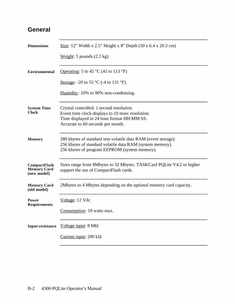
B-2 4300-PQLite Operator’s Manual
General
Dimensions Size: 12” Width x 2.5” Height x 8” Depth (30 x 6.4 x 20.3 cm)
Weight: 5 pounds (2.2 kg)
Environmental Operating: 5 to 45 °C (41 to 113 °F)
Storage: -20 to 55 °C (-4 to 131 °F).
Humidity: 10% to 90% non-condensing.
System Time Clock
Crystal controlled. 1 second resolution.Event time clock displays to 10 msec resolution.Time displayed in 24 hour format HH:MM:SS.Accurate to 60 seconds per month.
Memory 280 kbytes of standard non-volatile data RAM (event storage).256 kbytes of standard volatile data RAM (system memory). 256 kbytes of program EEPROM (system memory).
CompactFlash Memory Card (new model)
Sizes range from 8Mbytes to 32 Mbytes. TASKCard PQLite V4.2 or higher support the use of CompactFlash cards.
Memory Card (old model)
2Mbytes to 4 Mbytes depending on the optional memory card capacity.
Power Requirements
Voltage: 12 Vdc.
Consumption: 18 watts max.
Input resistance Voltage input: 8 MΩ
Current input: 200 kΩ
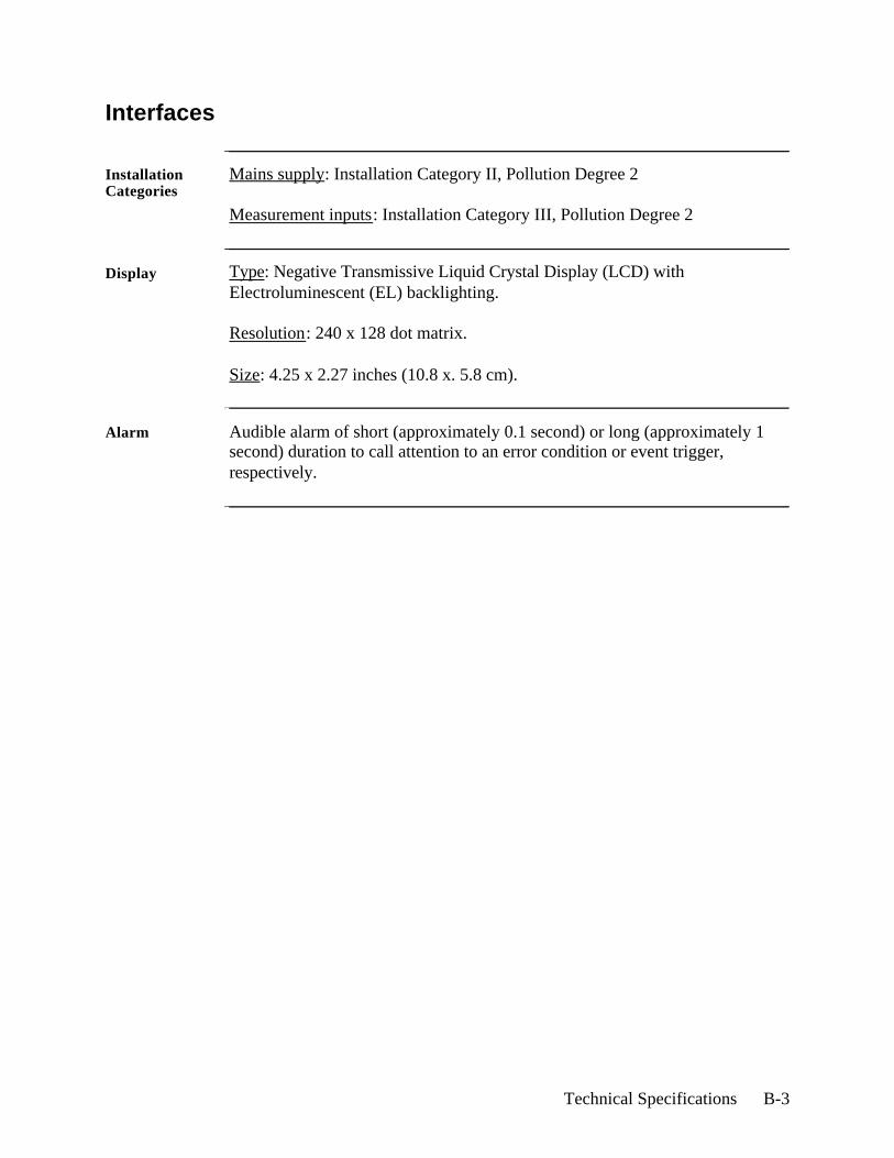
Technical Specifications B-3
Interfaces
Installation Categories
Mains supply: Installation Category II, Pollution Degree 2
Measurement inputs: Installation Category III, Pollution Degree 2
Display Type: Negative Transmissive Liquid Crystal Display (LCD) with Electroluminescent (EL) backlighting.
Resolution: 240 x 128 dot matrix.
Size: 4.25 x 2.27 inches (10.8 x. 5.8 cm).
Alarm Audible alarm of short (approximately 0.1 second) or long (approximately 1 second) duration to call attention to an error condition or event trigger, respectively.
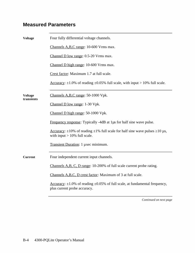
B-4 4300-PQLite Operator’s Manual
Measured Parameters
Voltage Four fully differential voltage channels.
Channels A,B,C range: 10-600 Vrms max.
Channel D low range: 0.5-20 Vrms max.
Channel D high range: 10-600 Vrms max.
Crest factor: Maximum 1.7 at full scale.
Accuracy: ±1.0% of reading ±0.05% full scale, with input > 10% full scale.
Voltage transients
Channels A,B,C range: 50-1000 Vpk.
Channel D low range: 1-30 Vpk.
Channel D high range: 50-1000 Vpk.
Frequency response: Typically -4dB at 1µs for half sine wave pulse.
Accuracy: ±10% of reading ±1% full scale for half sine wave pulses ≥10 µs, with input > 10% full scale.
Transient Duration: 1 µsec minimum.
Current Four independent current input channels.
Channels A,B, C, D range: 10-200% of full scale current probe rating.
Channels A,B,C, D crest factor: Maximum of 3 at full scale.
Accuracy: ±1.0% of reading ±0.05% of full scale, at fundamental frequency, plus current probe accuracy.
Continued on next page
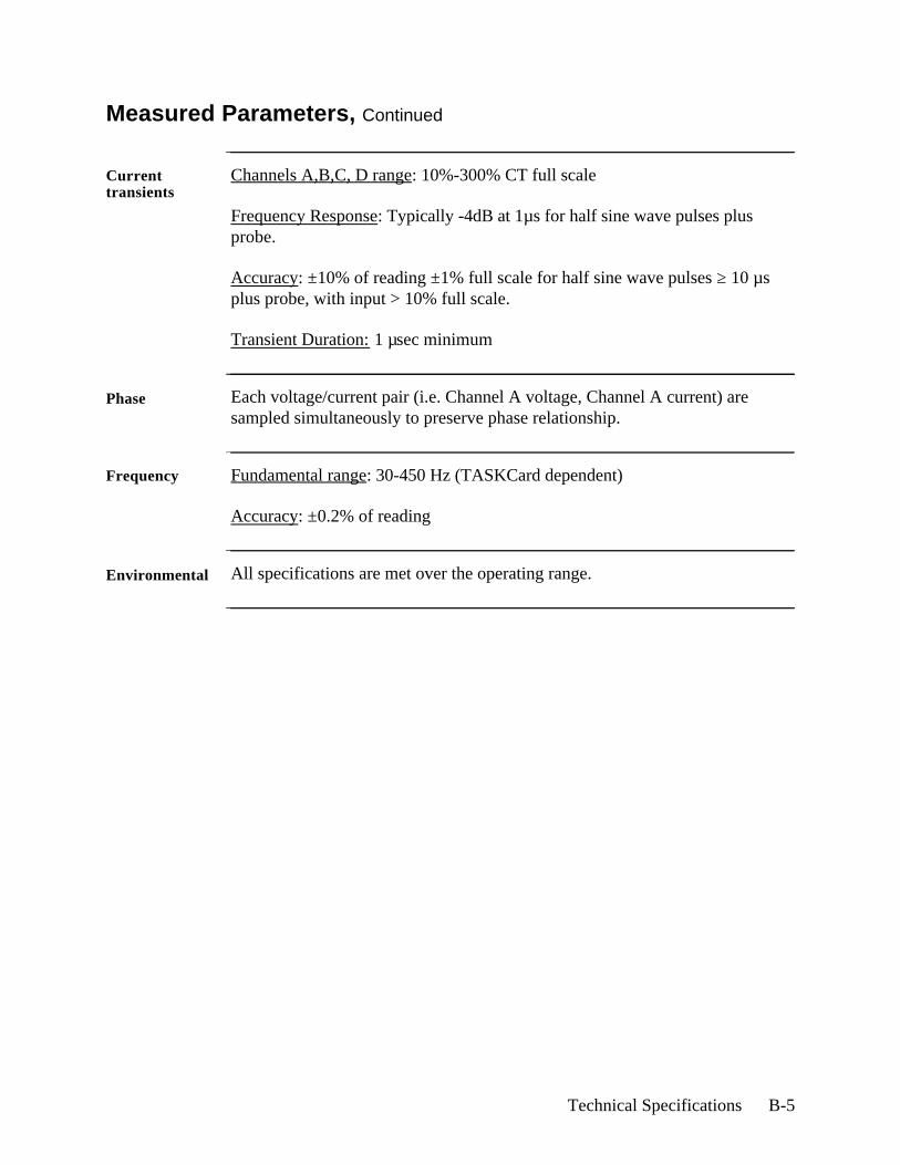
Technical Specifications B-5
Measured Parameters, Continued
Current transients
Channels A,B,C, D range: 10%-300% CT full scale
Frequency Response: Typically -4dB at 1µs for half sine wave pulses plus probe.
Accuracy: ±10% of reading ±1% full scale for half sine wave pulses ≥ 10 µs plus probe, with input > 10% full scale.
Transient Duration: 1 µsec minimum
Phase Each voltage/current pair (i.e. Channel A voltage, Channel A current) are sampled simultaneously to preserve phase relationship.
Frequency Fundamental range: 30-450 Hz (TASKCard dependent)
Accuracy: ±0.2% of reading
Environmental All specifications are met over the operating range.
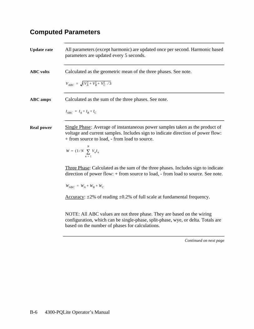
B-6 4300-PQLite Operator’s Manual
Computed Parameters
Update rate All parameters (except harmonic) are updated once per second. Harmonic based parameters are updated every 5 seconds.
ABC volts Calculated as the geometric mean of the three phases. See note.
ABC amps Calculated as the sum of the three phases. See note.
Real power Single Phase: Average of instantaneous power samples taken as the product of voltage and current samples. Includes sign to indicate direction of power flow:+ from source to load, - from load to source.
Three Phase: Calculated as the sum of the three phases. Includes sign to indicate direction of power flow: + from source to load, - from load to source. See note.
Accuracy: ±2% of reading ±0.2% of full scale at fundamental frequency.
NOTE: All ABC values are not three phase. They are based on the wiring configuration, which can be single-phase, split-phase, wye, or delta. Totals are based on the number of phases for calculations.
Continued on next page
VABC VA2 VB
2 VC2+ +( ) 3⁄=
IABC IA IB IC+ +=
W 1 N⁄( ) VnIn
n 1=
N
∑=
WABC WA WB WC+ +=
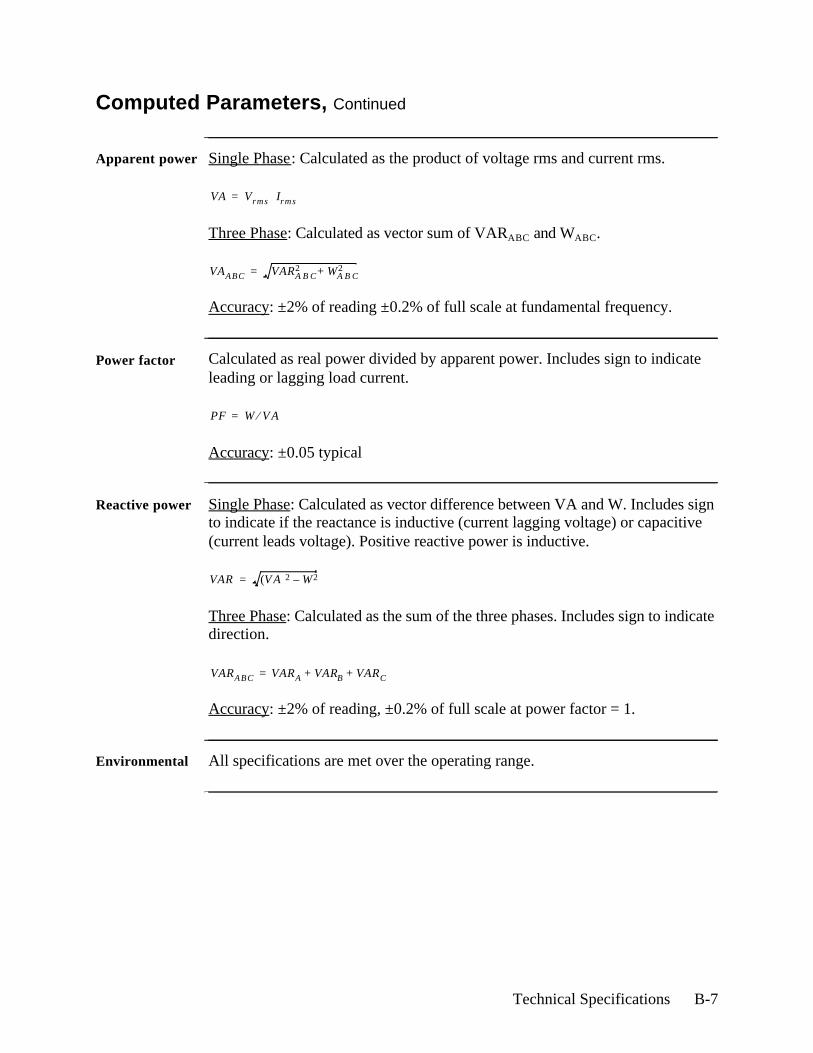
Technical Specifications B-7
Computed Parameters, Continued
Apparent power Single Phase: Calculated as the product of voltage rms and current rms.
Three Phase: Calculated as vector sum of VARABC and WABC.
Accuracy: ±2% of reading ±0.2% of full scale at fundamental frequency.
Power factor Calculated as real power divided by apparent power. Includes sign to indicate leading or lagging load current.
Accuracy: ±0.05 typical
Reactive power Single Phase: Calculated as vector difference between VA and W. Includes sign to indicate if the reactance is inductive (current lagging voltage) or capacitive (current leads voltage). Positive reactive power is inductive.
Three Phase: Calculated as the sum of the three phases. Includes sign to indicate direction.
Accuracy: ±2% of reading, ±0.2% of full scale at power factor = 1.
Environmental All specifications are met over the operating range.
VA Vrms Irms⋅=
VAABC VARA B C2 WA B C
2+=
PF W V A⁄=
VAR V A( )2 W2–=
VARABC VARA VARB VARC+ +=
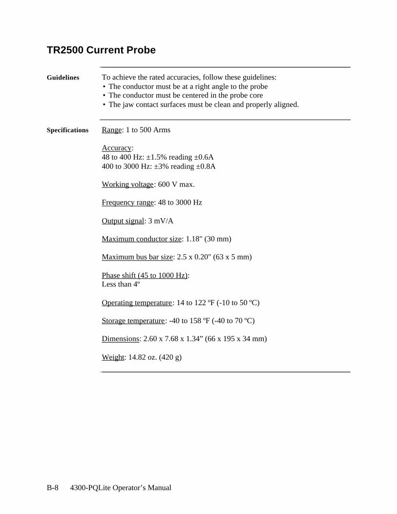
B-8 4300-PQLite Operator’s Manual
TR2500 Current Probe
Guidelines To achieve the rated accuracies, follow these guidelines:• The conductor must be at a right angle to the probe• The conductor must be centered in the probe core• The jaw contact surfaces must be clean and properly aligned.
Specifications Range: 1 to 500 Arms
Accuracy: 48 to 400 Hz: ±1.5% reading ±0.6A400 to 3000 Hz: ±3% reading ±0.8A
Working voltage: 600 V max.
Frequency range: 48 to 3000 Hz
Output signal: 3 mV/A
Maximum conductor size: 1.18" (30 mm)
Maximum bus bar size: 2.5 x 0.20" (63 x 5 mm)
Phase shift (45 to 1000 Hz): Less than 4º
Operating temperature: 14 to 122 ºF (-10 to 50 ºC)
Storage temperature: -40 to 158 ºF (-40 to 70 ºC)
Dimensions: 2.60 x 7.68 x 1.34” (66 x 195 x 34 mm)
Weight: 14.82 oz. (420 g)
Battery Specifications and Replacement Procedure C-1
Appendix C
Battery Specifications and Replacement Procedure
Overview
Introduction The internal battery pack used in the 4300 functions as the primary power source and UPS; the memory card contains an easily replaceable battery.
The 4300 CPU contains a storage capacitor for memory backup but is not operator replaceable.
In this appendix The following topics are covered in this appendix.
Topic See Page
Battery Specifications C-2
Battery Pack Safety Precautions C-3
Battery Pack Replacement C-5
Memory Card Battery Replacement C-7
C-2 4300-PQLite Operator’s Manual
Battery Specifications
Battery pack Location: Battery compartment on the bottom of the unit.
Number of batteries in pack: 6
Type: Sealed, rechargeable NiCad cells
Voltage: 7.2 V dc
Capacity: 1.6 Ah
Length of operation: More than two hours when fully charged.
Suggested replacement interval: Two years.
Part Number: BP4300
NOTE: The length of time that the 4300 can operate on the battery pack degrades over the life of the batteries and the number of charge/discharge cycles.
Memory backup A storage capacitor on the CPU board is used for backup of the 4300’s data, configurations, and setup when the battery pack is removed. The capacitor’s charge will maintain memory for two hours. The capacitor is not operator replaceable.
Battery Specifications and Replacement Procedure C-3
Battery Pack Safety Precautions
WARNING DO NOT intentionally short circuit the battery pack. The batteries are capable of providing hazardous output currents if short circuited. The Power Platform is equipped with an internal battery charger circuit. Do not attempt to charge the batteries with an external charger other than the Dranetz battery charger, since improper charging could cause battery explosion.
ADVERTEN-CIA NO ponga intencionalmente la batería en cortocircuito. Las baterías son
capaces de proporcionar corrientes de salida peligrosas si están en cortocircuito. La Power Platform está equipada con un circuito interno cargador de baterías. No intente cargar las baterías con un cargador externo que no sea el cargador de baterías Dranetz, puesto que la carga indebida podría hacer que explote la batería.
AVERTISSE-MENT NE PAS court-circuiter délibérément le bloc-batterie. Lors d’un court-
circuit, les batteries risquent d’émettre des courants effectifs dangereux. “Power Platform” possède un circuit de chargeur de batterie intégré. Ne pas tenter de charger les batteries au moyen d’un chargeur externe autre que le chargeur de batterie Dranetz, car un rechargement fautif pourrait entraîner l’explosion de la batterie.
WARNUNG Die Batterien dürfen NICHT kurzgeschlossen werden. Im Falle eines Kurzschlusses können die Batterien lebensgefährliche Ausgangsströme leiten. Power Platform ist mit einem internen Batterieladegerät ausgestattet. Die Batterien sollten nur mit dem Ladegerät von Dranetz geladen werden. Die Verwendung eines externen Ladegeräts kann zu einer Explosion der Batterien führen.
Battery safety precautions
Observe the following precautions when inspecting or replacing the battery pack:• Do not attempt to replace individual batteries of the pack or substitute other
battery types.• Do not dispose of battery in fire.
Continued on next page

C-4 4300-PQLite Operator’s Manual
Battery Pack Safety Precautions, Continued
• Dispose of a used battery promptly in accordance with local Environmental Protection Agency (EPA) regulations.
• Visually inspect the battery pack for corrosion:
The batteries have a safety pressure vent to prevent excessive gas build-up and corrosion indicates that venting has occurred. Possible causes of venting are: a defective charger, excessive temperature, excessive discharge rate, or a defective cell.
If corrosion is excessive, the battery pack may require replacement (contact Dranetz Customer Service Department).

Battery Specifications and Replacement Procedure C-5
Battery Pack Replacement
Introduction The 4300 contains an easily replaceable internal battery pack. See Appendix D for ordering information.
WARNING Replace with Dranetz Ni-Cad battery pack BP4300 only.
ADVERTEN-CIA
Reemplace con batería Dranetz Ni-Cad BP4300 solamente.
AVERTISSE-MENT
Remplacer par la batterie Dranetz Ni-Cad BP4300 exclusivement.
WARNUNG Nur mit Dranetz Ni-Cad BP4300 Batteriesatz auswechseln.
Note During normal operation, the battery pack will be slightly warm to the touch.
Procedure Follow these steps to replace the battery pack.
Continued on next page
Step Action
1 Press the 4300 power key to off.
2 Turn off power to the circuit being measured.
3 Disconnect voltage and current probes from the circuit and the 4300’s rear panel.
4 On the bottom of the 4300, push the tab to release the battery cover. Refer to the diagram shown below.
5 Remove the cover.
6 Pull up on removal strap and remove battery pack.
7 Insert the new pack into the compartment making sure to observe polarity markings.
8 Replace the cover and press down until it latches closed.
9 Discard the old battery pack in accordance with Environmental Protection Agency (EPA) regulations.
10 Press the 4300 power key to on.
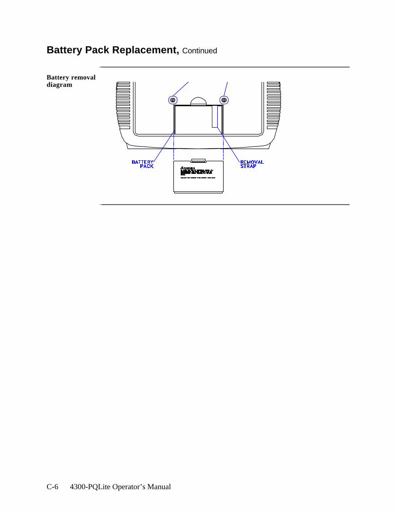
C-6 4300-PQLite Operator’s Manual
Battery Pack Replacement, Continued
Battery removal diagram
Battery Specifications and Replacement Procedure C-7
Memory Card Battery Replacement
Introduction Replacement of the 3-volt lithium battery in the memory card is performed when the battery message in the Memory Card Function screen states the battery is depleted. Replacement is simple and requires no special tools. Two physically different types of batteries are used due to different manufacturers of the memory card. The correct replacement type must be used.
WARNING The battery used in this device may present a fire or chemical burn hazardif mistreated. Do not recharge, disassemble, or dispose of in fire. Replace battery with Panasonic BR2325 or CR2025 only. Use of another type battery may present a risk of fire or explosion.
ADVERTEN-CIA La batería empleada en este dispositivo puede presentar un peligro de
incendio o quemadura química si se manipula indebidamente. No recargue, desarme ni deseche en el fuego. Cambie la batería por una Panasonic BR2325 o CR2025 solamente. El uso de cualquier otro tipo de batería puede presentar un peligro de incendio o explosión.
AVERTISSE-MENT La batterie utilisée dans cette unité peut présenter des risques d’incendie
ou de brûlures chimiques par suite d’une utilisation abusive. Ne pas recharger, démonter, ni jeter au feu. Remplacer uniquement la batterie par une batterie Panasonic BR2325 ou CR2025. L’utilisation d’un tout autre modèle de batterie peut entraîner des risques d’incendie ou d’explosion.
WARNUNG Die in diesem Gerät verwendete Batterie kann im Falle einer unsachgemäßen Behandlung zu Bränden oder chemischen Verätzungen führen. Sie sollte nicht wiederaufgeladen, auseinandergenommen oder verbrannt werden. Ersetzen Sie die Batterie nur mit Batterien vom Typ Panasonic BR2325 oder CR2025. Die Verwendung eines anderen Batterietyps kann Brände oder Explosionen hervorrufen.
Continued on next page
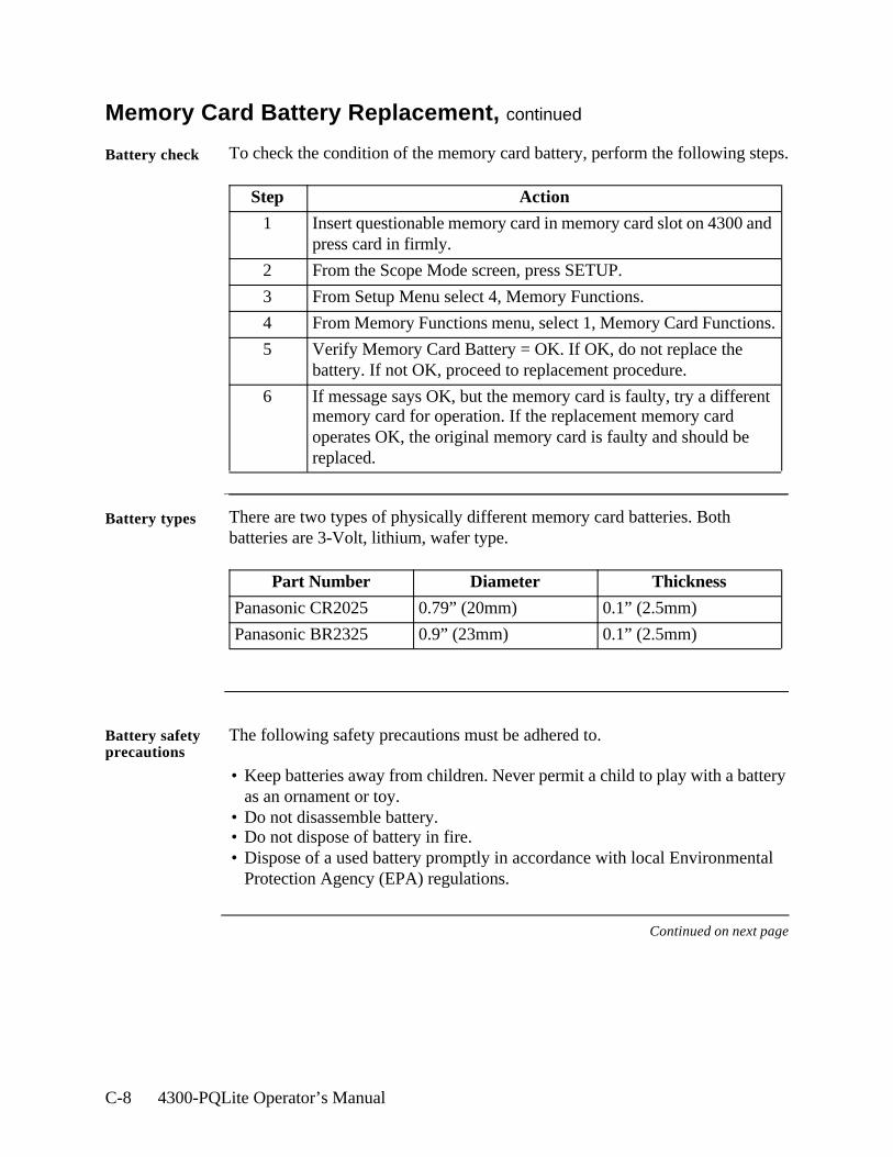
C-8 4300-PQLite Operator’s Manual
Memory Card Battery Replacement, continued
Battery check To check the condition of the memory card battery, perform the following steps.
Battery types There are two types of physically different memory card batteries. Both batteries are 3-Volt, lithium, wafer type.
Battery safety precautions
The following safety precautions must be adhered to.
• Keep batteries away from children. Never permit a child to play with a battery as an ornament or toy.
• Do not disassemble battery.• Do not dispose of battery in fire.• Dispose of a used battery promptly in accordance with local Environmental
Protection Agency (EPA) regulations.
Continued on next page
Step Action
1 Insert questionable memory card in memory card slot on 4300 and press card in firmly.
2 From the Scope Mode screen, press SETUP.
3 From Setup Menu select 4, Memory Functions.
4 From Memory Functions menu, select 1, Memory Card Functions.
5 Verify Memory Card Battery = OK. If OK, do not replace the battery. If not OK, proceed to replacement procedure.
6 If message says OK, but the memory card is faulty, try a different memory card for operation. If the replacement memory card operates OK, the original memory card is faulty and should be replaced.
Part Number Diameter Thickness
Panasonic CR2025 0.79” (20mm) 0.1” (2.5mm)
Panasonic BR2325 0.9” (23mm) 0.1” (2.5mm)
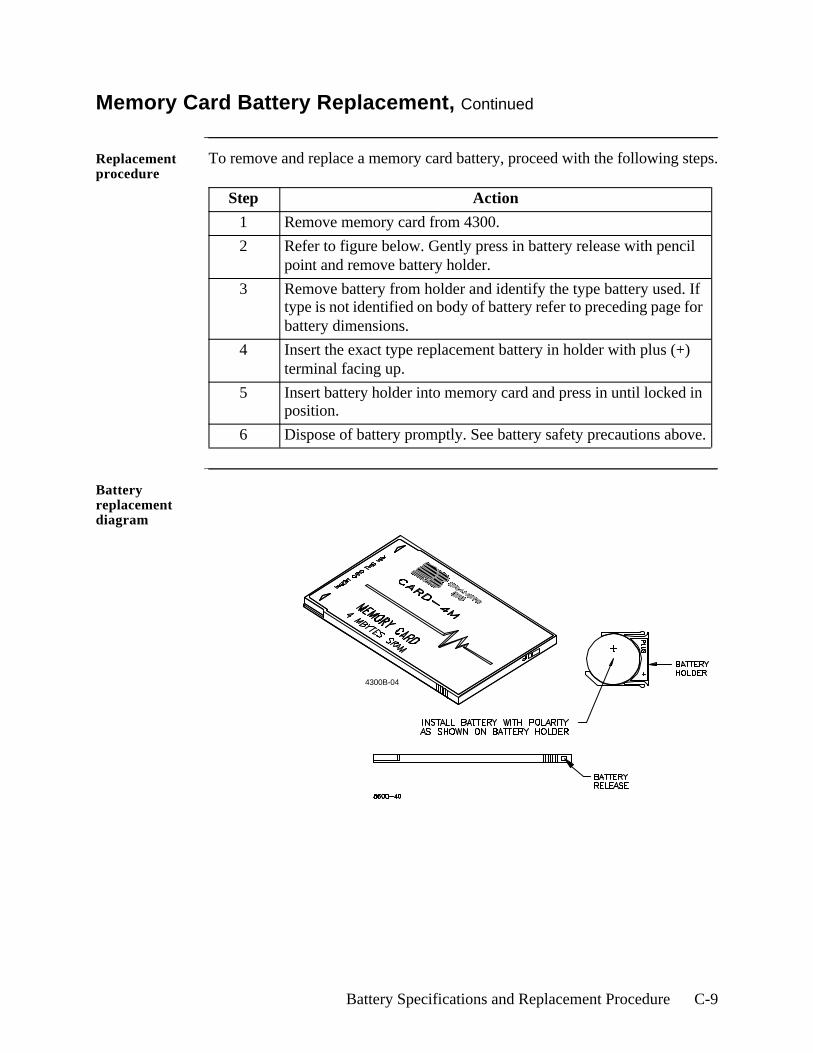
Battery Specifications and Replacement Procedure C-9
Memory Card Battery Replacement, Continued
Replacement procedure
To remove and replace a memory card battery, proceed with the following steps.
Battery replacement diagram
Step Action
1 Remove memory card from 4300.
2 Refer to figure below. Gently press in battery release with pencil point and remove battery holder.
3 Remove battery from holder and identify the type battery used. If type is not identified on body of battery refer to preceding page for battery dimensions.
4 Insert the exact type replacement battery in holder with plus (+) terminal facing up.
5 Insert battery holder into memory card and press in until locked in position.
6 Dispose of battery promptly. See battery safety precautions above.
4300B-04

C-10 4300-PQLite Operator’s Manual
Operator Replaceable Parts List D-1
Appendix D
Operator Replaceable Parts List
Introduction The following parts are easily replaced by the operator and do not require special tools or access to the interior of the unit.
To order parts Call Dranetz Customer Service at (732) 287-3680 or 1-800-DRANTECto order any of the following parts.
Parts List
Measurement cable set, parts list
Part Description Part Number
AC Adapter/Battery Charger 116297-G1
Battery Door 116037-G1
Battery Pack BP-4300
Rubber Skin 116035-G1
Voltage Cable Assembly, 4 Pair w/ Alligator Probes (See below for separate parts)
116042-G1
Part Description Quantity Part Number
Alligator Clip, 4MM Plug-on, Red 4 900371
Alligator Clip, 4MM Plug-on, Black 4 900372
1000V Cable, Red 1 900366
Yellow Cable/Plug 1 900367
6FT Cable/Plug Blue, 4300 1 900368
6FT Cable/Plug Gray, 4300 1 900369
6FT Cable/Plug White, 4300 1 900370
Carry Strap 1 116040-G1
Cable Pouch, PP4300 1 116043-G1

D-2 4300-PQLite Operator’s Manual
System Messages E-1
Appendix E
System Messages
Overview
Introduction Display messages provide you with 4300 operating information or tell you about an error condition. This appendix describes the types of messages that can appear, lists the messages, and gives instructions about what to do next. Self-explanatory messages are not included.
In this appendix The following topics are covered in this appendix.
Topic See Page
Message Types E-2
Messages E-3

E-2 4300-PQLite Operator’s Manual
Message Types
Introduction There are three types of messages: Normal One-Line, Important One-Line, and Full Screen.When a message is displayed it is automatically saved to memory for recall at a later time.
One-line messages
All one-line messages are displayed on the top line of the screen between the time and date, and are a maximum of 21 characters long. They are displayed as long as the condition exists.
Normal one-line messages: Normal one-line messages are displayed in regular text.
Important one-line messages: Important one-line messages are displayed in reverse video.
Full screen messages
Full screen messages warn you of potential system problems. You must press a key to remove the screen message.
Priority In general, a more important message will take priority over a less important one, with the exception of full screen messages which are displayed until you press a key.
When two or more one-line message are active, they are alternately cycled every two seconds. The priority is as follow:
Priority Description
1 All new one-line messages are displayed immediately, accompanied by a short beep, then normal message cycling is resumed.
2 When there are important one-line messages, only these will be cycled until they are cleared.
3 When there is only one important one-line message displayed, no normal one-line messages will cycle until the displayed message is cleared.
4 No one-line messages are displayed on HELP screens, but full screen messages will operate normally.
5 Full screen messages will always take precedence over any type of one-line display.
System Messages E-3
Messages
One-line messages
Sync Lost Ch A, B, C, or D.The unit cannot synchronize to the specified channel. Either no voltage or a voltage outside the sync range is being applied. If the unit continues to switch between Sync Lost and Sync Acquired, you may have to change to internal sync.
Sync Acquired-Ch A, B, C, or D.The unit has synchronized to the specified voltage channel.
Probe Ch A, B, C, or D-Connect.A current probe has been connected to the specified channel.
Probe Ch A, B, C, or D-Disconnect.The current probe on the specified channel has been disconnected.
Volts Overload Ch-A, B, C, or D.The voltage range for the specified channel has been exceeded.
Amps Overload Ch-A, B, C, or D.The current range for the specified channel has been exceeded. Use a probe with a range appropriate for your measurements.
Volts Overrange Ch A, B, C, or D.The voltage safety limit for the specified channel has been exceeded. Turn off power to the circuit and disconnect the unit.
Amps Overrange Ch A, B, C, or D.The current safety limit for the specified channel has been exceeded. Turn off power to circuit and disconnect the unit.
Continued on next page
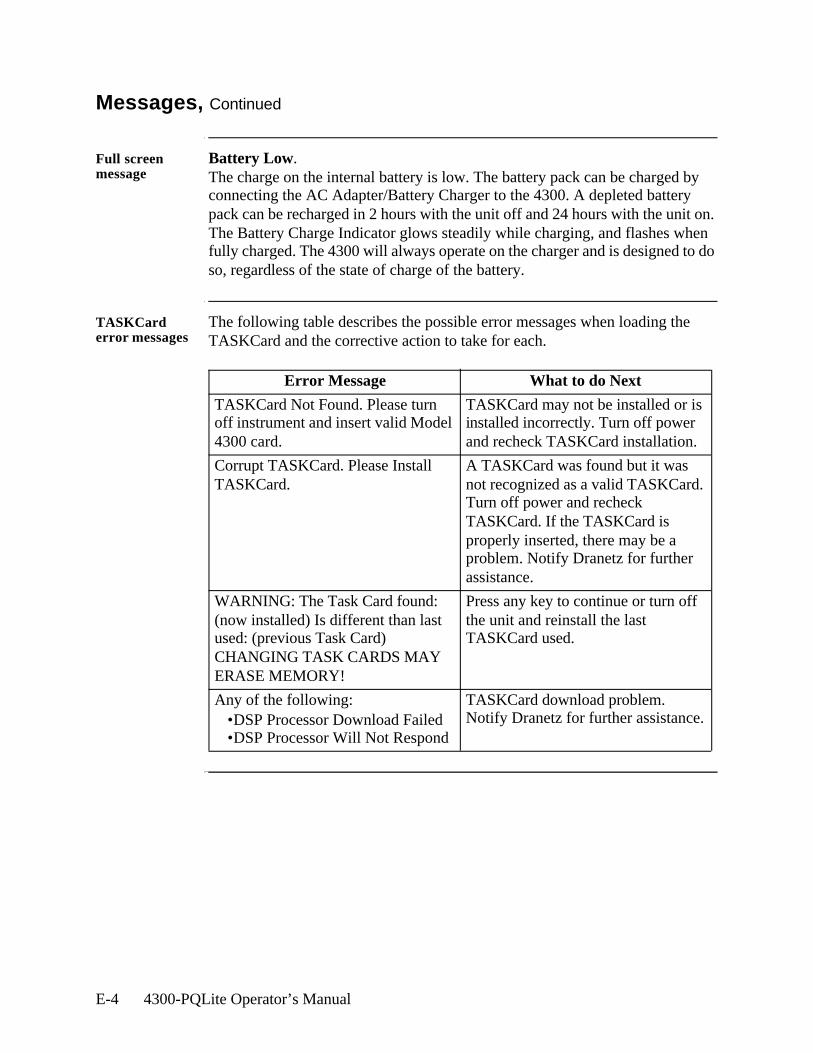
E-4 4300-PQLite Operator’s Manual
Messages, Continued
Full screen message
Battery Low.The charge on the internal battery is low. The battery pack can be charged by connecting the AC Adapter/Battery Charger to the 4300. A depleted battery pack can be recharged in 2 hours with the unit off and 24 hours with the unit on. The Battery Charge Indicator glows steadily while charging, and flashes when fully charged. The 4300 will always operate on the charger and is designed to do so, regardless of the state of charge of the battery.
TASKCard error messages
The following table describes the possible error messages when loading the TASKCard and the corrective action to take for each.
Error Message What to do Next
TASKCard Not Found. Please turn off instrument and insert valid Model 4300 card.
TASKCard may not be installed or is installed incorrectly. Turn off power and recheck TASKCard installation.
Corrupt TASKCard. Please Install TASKCard.
A TASKCard was found but it was not recognized as a valid TASKCard. Turn off power and recheck TASKCard. If the TASKCard is properly inserted, there may be a problem. Notify Dranetz for further assistance.
WARNING: The Task Card found: (now installed) Is different than last used: (previous Task Card) CHANGING TASK CARDS MAY ERASE MEMORY!
Press any key to continue or turn off the unit and reinstall the last TASKCard used.
Any of the following:•DSP Processor Download Failed•DSP Processor Will Not Respond
TASKCard download problem. Notify Dranetz for further assistance.
Common Circuit Connections F-1
Appendix F
Common Circuit Connections
Overview
Who should read this section
If you are making power measurements, follow these diagrams so that your ABC values are calculated correctly.
WARNING Death, serious injury, or fire hazard could result from improper connection of this instrument. Read and understand this manual before connecting this instrument. Follow all installation and operating instructions while using this instrument.
Connection of this instrument must be performed in compliance with the National Electrical Code (ANSI/NFPA 70-2002) and any additional safety requirements applicable to your installation.
Installation, operation, and maintenance of this instrument must be performed by qualified personnel only. The National Electrical Code defines a qualified person as “one who has the skills and knowledge related to the construction and operation of the electrical equipment and installations, and who has received safety training on the hazards involved.”
Qualified personnel who work on or near exposed energized electrical conductors must follow applicable safety related work practices and procedures including appropriate personal protective equipment in compliance with the Standard for Electrical Safety Requirements for Employee Workplaces (ANSI/NFPA 70E-2000) of USA and any additional workplace safety requirements applicable to your installation.
ADVERTEN-CIA
Una conexión incorrecta de este instrumento puede producir la muerte, lesiones graves y riesgo de incendio. Lea y entienda este manual antes de conectar. Observe todas las instrucciones de instalación y operación durante el uso de este instrumento.
La conexión de este instrumento debe ser hecha de acuerdo con las normas del Código Eléctrico Nacional (ANSI/NFPA 70-2002) de EE. UU., además de cualquier otra norma de seguridad correspondiente a su establecimiento.
La instalación, operación y mantenimiento de este instrumento debe ser realizada por personal calificado solamente. El Código Eléctrico Nacional define a una persona calificada como "una que esté familiarizada con la construcción y operación del equipo y con los riesgos involucrados."
Continued on next page
F-2 4300-PQLite Operator’s Manual
Overview, Continued
AVERTISSE-MENT
Si l'instrument est mal connecté, la mort, des blessures graves, ou un danger d'incendie peuvent s'en suivre. Lisez attentivement ce manuel avant de connecter l'instrument. Lorsque vous utilisez l'instrument, suivez toutes les instructions d'installation et de service.
Cet instrument doit être connecté conformément au National Electrical Code (ANSI/NFPA 70-2002) des Etats-Unis et à toutes les exigences de sécurité applicables à votre installation.
Cet instrument doit être installé, utilisé et entretenu uniquement par un personnel qualifié. Selon le National Electrical Code, une personne est qualifiée si "elle connaît bien la construction et l'utilisation de l'équipement, ainsi que les dangers que cela implique".
WARNUNG Der falsche Anschluß dieses Gerätes kann Tod, schwere Verletzungen oder Feuer verursachen. Bevor Sie dieses Instrument anschließen, müssen Sie die Anleitung lesen und verstanden haben. Bei der Verwendung dieses Instruments müssen alle Installation- und Betriebsanweisungen beachtet werden.
Der Anschluß dieses Instruments muß in Übereinstimmung mit den nationalen Bestimmungen für Elektrizität (ANSI/NFPA 70-2002) der Vereinigten Staaten, sowie allen weiteren, in Ihrem Fall anwendbaren Sicherheitsbestimmungen, vorgenommen werden.
Installation, Betrieb und Wartung dieses Instruments dürfen nur von Fachpersonal durchgeführt werden. In dem nationalen Bestimmungen für Elektrizität wird ein Fachmann als eine Person bezeichnet, welche "mit der Bauweise und dem Betrieb des Gerätes sowie den dazugehörigen Gefahren vertraut ist."
Continued on next page
Common Circuit Connections F-3
Overview, Continued
WARNING To avoid the risk of electric shock or burns, always connect the safety (or earth) ground before making any other connections.
WARNING To reduce the risk of fire, electrical shock, or physical injury it is strongly recommended to fuse the voltage measurement inputs.Fuses must be located as close to the load as possible to maximize protection.
WARNING For continued protection against risk of fire or shock hazard replace only with same type and rating of recommended fuse.Use only fast blow type fuse which is rated 600V. Recommended fuse type is Littelfuse, part number KLKD0.25 rated 600V AC/DC, 0.25 A fast blow.
WARNING Do not replace fuse again if failure is repeated. Repeated failure indicates a defective condition that will not clear with replacement of the fuse. Refer condition to a qualified technician.
Safety precautions
The following safety precautions must be followed whenever any type of voltage or current connection is being made to the 4300.• Wear proper Personal Protective Equipment, including safety glasses and
insulated gloves when making connections to power circuits.• Hands, shoes and floor must be dry when making any connection to a power
line.• Before each use, inspect all cables for breaks or cracks in the insulation.
Replace immediately if defective.• Set the 4300 power switch to Off.• Before connecting to electric circuits to be monitored, open their related
circuit breakers or disconnects. DO NOT install any connection of the 4300 to live power lines.
• Connections must be made to the 4300 first, then connect to the circuit to be monitored.
Continued on next page
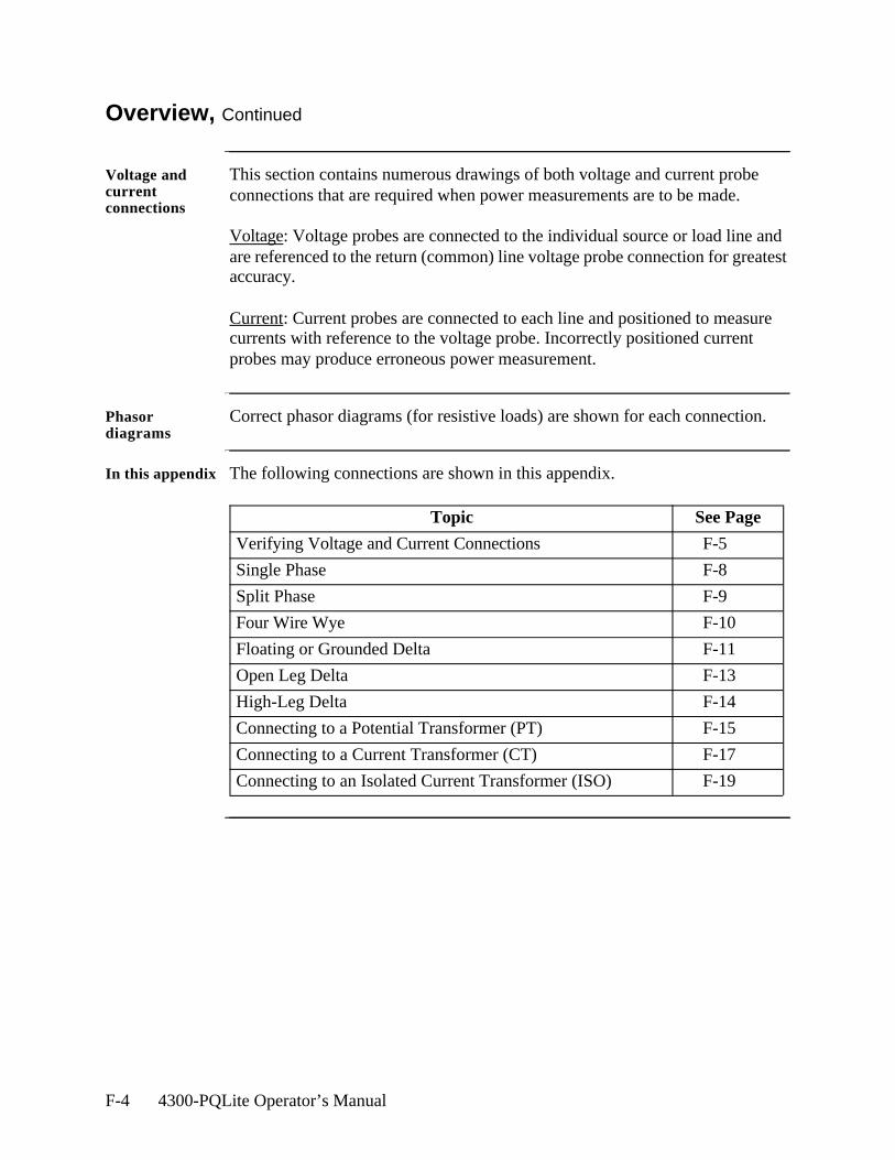
F-4 4300-PQLite Operator’s Manual
Overview, Continued
Voltage and current connections
This section contains numerous drawings of both voltage and current probe connections that are required when power measurements are to be made.
Voltage: Voltage probes are connected to the individual source or load line and are referenced to the return (common) line voltage probe connection for greatest accuracy.
Current: Current probes are connected to each line and positioned to measure currents with reference to the voltage probe. Incorrectly positioned current probes may produce erroneous power measurement.
Phasor diagrams
Correct phasor diagrams (for resistive loads) are shown for each connection.
In this appendix The following connections are shown in this appendix.
Topic See Page
Verifying Voltage and Current Connections F-5
Single Phase F-8
Split Phase F-9
Four Wire Wye F-10
Floating or Grounded Delta F-11
Open Leg Delta F-13
High-Leg Delta F-14
Connecting to a Potential Transformer (PT) F-15
Connecting to a Current Transformer (CT) F-17
Connecting to an Isolated Current Transformer (ISO) F-19
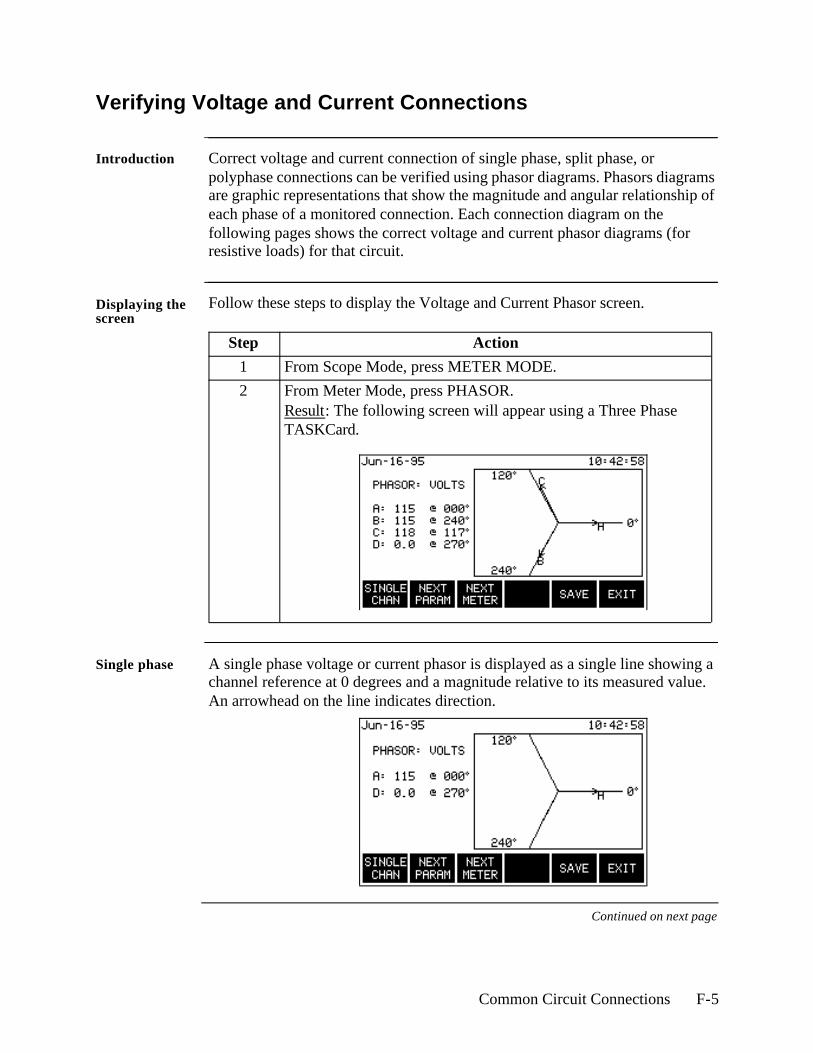
Common Circuit Connections F-5
Verifying Voltage and Current Connections
Introduction Correct voltage and current connection of single phase, split phase, or polyphase connections can be verified using phasor diagrams. Phasors diagrams are graphic representations that show the magnitude and angular relationship of each phase of a monitored connection. Each connection diagram on the following pages shows the correct voltage and current phasor diagrams (for resistive loads) for that circuit.
Displaying the screen
Follow these steps to display the Voltage and Current Phasor screen.
Single phase A single phase voltage or current phasor is displayed as a single line showing a channel reference at 0 degrees and a magnitude relative to its measured value. An arrowhead on the line indicates direction.
Continued on next page
Step Action
1 From Scope Mode, press METER MODE.
2 From Meter Mode, press PHASOR.Result: The following screen will appear using a Three Phase TASKCard.

F-6 4300-PQLite Operator’s Manual
Verifying Voltage and Current Connections, Continued
Split phase Split phase vectors are displayed as dual lines showing channel references and magnitudes and opposite (180 degrees) directions.
Three phase Three phase vectors are displayed as three lines, 120 degrees apart in a resistive load (unity power factor). Phase displacement will occur in a reactive load.
Correct 3-phase voltage phasor connections
The voltage phasor display shown below is for a three phase, four wire, wye connection.
Correct 3-phase current phasor connections
The current phasor display shown below is for a three phase, 4 wire wye connection.
Continued on next page
4300-43
4300-98
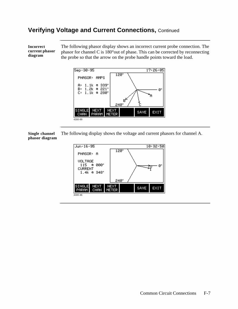
Common Circuit Connections F-7
Verifying Voltage and Current Connections, Continued
Incorrect current phasor diagram
The following phasor display shows an incorrect current probe connection. The phasor for channel C is 180°out of phase. This can be corrected by reconnecting the probe so that the arrow on the probe handle points toward the load.
Single channel phasor diagram
The following display shows the voltage and current phasors for channel A.
4300-99
4300-46
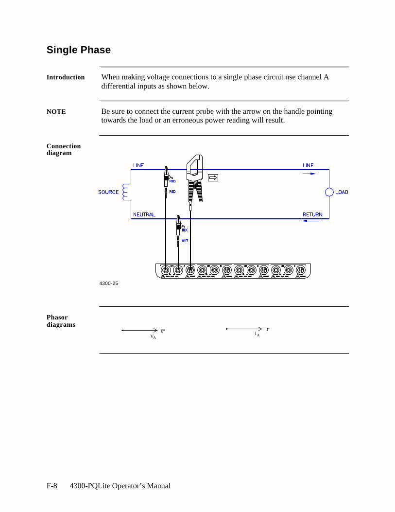
F-8 4300-PQLite Operator’s Manual
Single Phase
Introduction When making voltage connections to a single phase circuit use channel A differential inputs as shown below.
NOTE Be sure to connect the current probe with the arrow on the handle pointing towards the load or an erroneous power reading will result.
Connection diagram
Phasor diagrams
4300-25
0ºVA
0ºIA
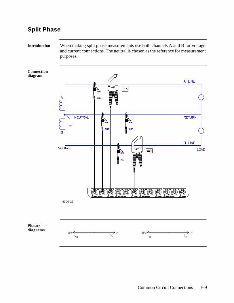
Common Circuit Connections F-9
Split Phase
Introduction When making split phase measurements use both channels A and B for voltage and current connections. The neutral is chosen as the reference for measurement purposes.
Connection diagram
Phasor diagrams
4300-26
0º180ºVAVB
0º180ºIAIB

F-10 4300-PQLite Operator’s Manual
Four Wire Wye
Introduction Channels A, B, and C are connected to voltage and current probes. The neutral is connected to common and is the reference for the three channels.
Connection diagram
Phasor diagrams
4300-27
VA
VB
0º
120ºVC
240º
IA
IB
0º
120ºIC
240º
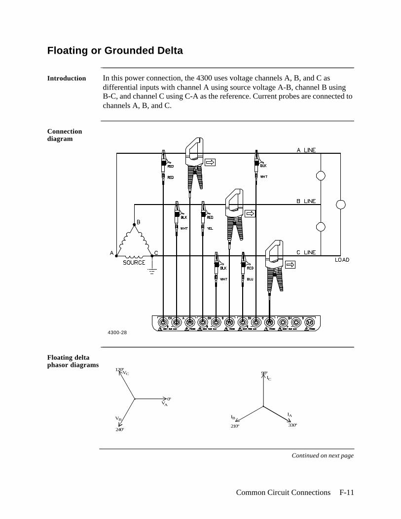
Common Circuit Connections F-11
Floating or Grounded Delta
Introduction In this power connection, the 4300 uses voltage channels A, B, and C as differential inputs with channel A using source voltage A-B, channel B using B-C, and channel C using C-A as the reference. Current probes are connected to channels A, B, and C.
Connection diagram
Floating delta phasor diagrams
Continued on next page
4300-28
VA
VB
0º
120ºVC
240º
IA
IC
330º
90º
IB
210º
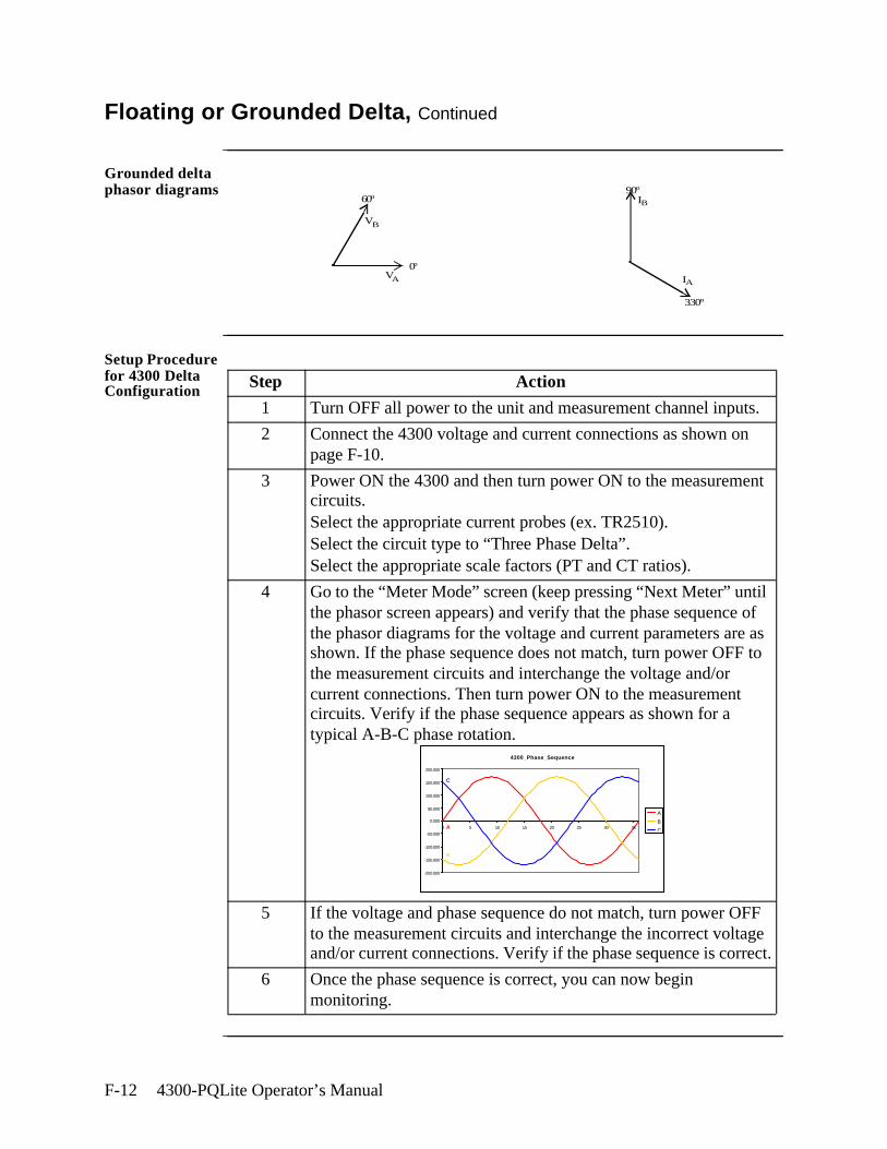
F-12 4300-PQLite Operator’s Manual
Floating or Grounded Delta, Continued
Grounded delta phasor diagrams
Setup Procedure for 4300 Delta Configuration Step Action
1 Turn OFF all power to the unit and measurement channel inputs.
2 Connect the 4300 voltage and current connections as shown on page F-10.
3 Power ON the 4300 and then turn power ON to the measurement circuits. Select the appropriate current probes (ex. TR2510). Select the circuit type to “Three Phase Delta”. Select the appropriate scale factors (PT and CT ratios).
4 Go to the “Meter Mode” screen (keep pressing “Next Meter” until the phasor screen appears) and verify that the phase sequence of the phasor diagrams for the voltage and current parameters are as shown. If the phase sequence does not match, turn power OFF to the measurement circuits and interchange the voltage and/or current connections. Then turn power ON to the measurement circuits. Verify if the phase sequence appears as shown for a typical A-B-C phase rotation.
5 If the voltage and phase sequence do not match, turn power OFF to the measurement circuits and interchange the incorrect voltage and/or current connections. Verify if the phase sequence is correct.
6 Once the phase sequence is correct, you can now begin monitoring.
VA
VB
0º
60º
IA
IB
330º
90º
4300_Phase_Sequence
-200.000
-150.000
-100.000
-50.000
0.000
50.000
100.000
150.000
200.000
0 5 10 15 20 25 30 35
A
B
CA
C
B
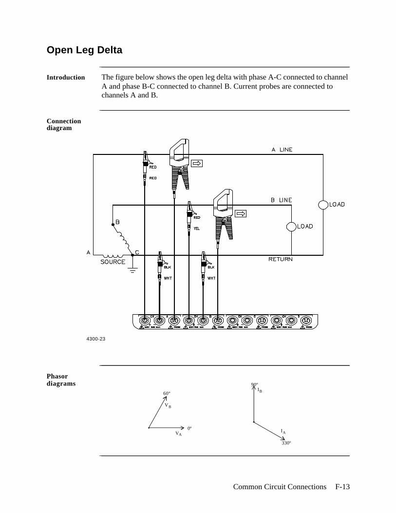
Common Circuit Connections F-13
Open Leg Delta
Introduction The figure below shows the open leg delta with phase A-C connected to channel A and phase B-C connected to channel B. Current probes are connected to channels A and B.
Connection diagram
Phasor diagrams
4300-23
VA
VB
0º
60º
IA
IB
330º
90º
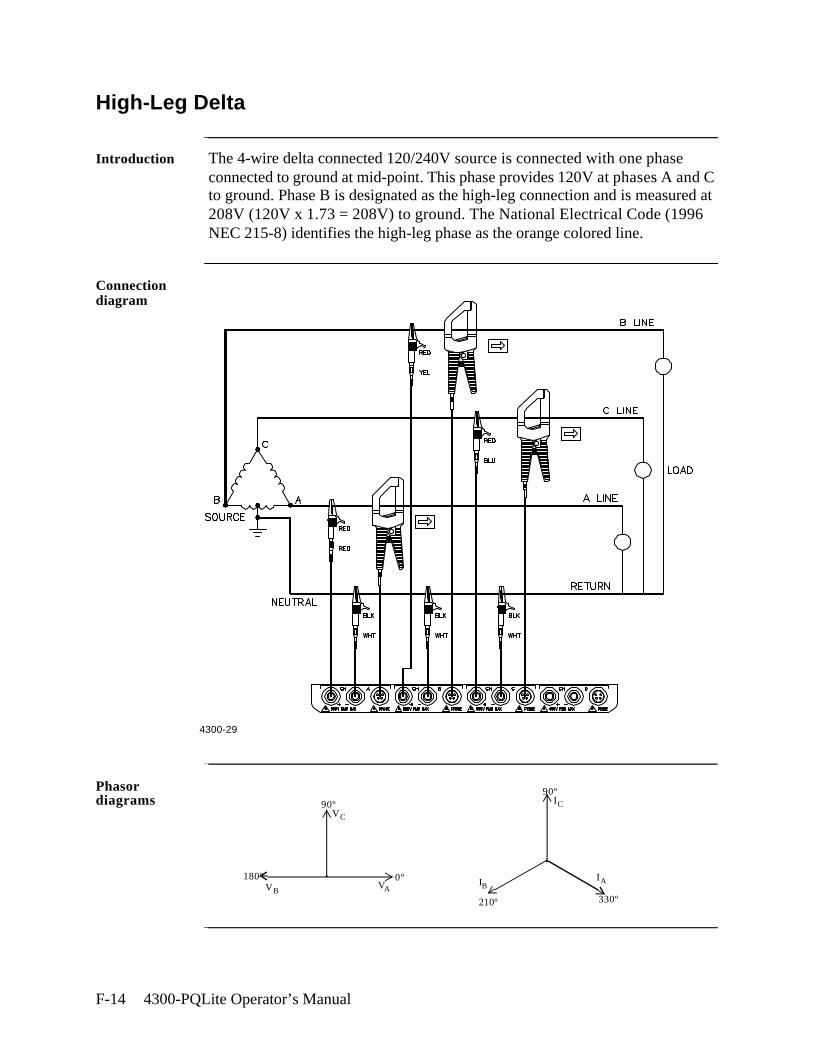
F-14 4300-PQLite Operator’s Manual
High-Leg Delta
Introduction The 4-wire delta connected 120/240V source is connected with one phase connected to ground at mid-point. This phase provides 120V at phases A and C to ground. Phase B is designated as the high-leg connection and is measured at 208V (120V x 1.73 = 208V) to ground. The National Electrical Code (1996 NEC 215-8) identifies the high-leg phase as the orange colored line.
Connection diagram
Phasor diagrams
4300-29
0º180ºVAVB
VC
90º
IA
IC
330º
90º
IB
210º
Common Circuit Connections F-15
Connecting to a Potential Transformer (PT)
Safety Precautions
Follow the safety precautions listed on page F-3 when making all potential transformer connections.
NOTE Potential Transformers are not manufactured by Dranetz and are discussed here for informational purposes only.
Definition A potential transformer (PT), also referred to as a voltage instrument transformer, provides the necessary step-down ratio to reduce the high voltage of circuits above 600 Vrms to a level for safe measurement. A PT also provides isolation and proper connections for instrument attachment.
Connections PTs are usually fixed in position and require that the voltage probe(s) be connected to their terminal connections.
WARNING Refer to the manufacturer’s instructions, related to the PT, for exact information for probe connection for voltage monitoring. Do not exceed 600 Vrms input to the 4300 voltage inputs.
ADVERTEN-CIA
Consulte las instrucciones del fabricante referentes a TP (transformador potencial), para la información exacta de la conexión de sonda a fin de monitorear el voltaje. No supere la entrada de 600 Vrms a las entradas de voltaje de 4300.
AVERTISSE-MENT
Se reporter aux instructions du fabricant relatives au transformateur de tension (Potential Transformer - PT) pour obtenir les renseignements exacts sur la connexion de sonde utilisée pour la surveillance du courant. Ne pas dépasser l’entrée de tension efficace de 600 RMS dans les entrées de tension de 4300 volts.
WARNUNG Genaue Informationen zur Meßfühlerverbindung für die Spannungsüberwachung entnehmen Sie bitte den Anleitungen des Herstellers (siehe Spannungsteilertransformator). Die Eingangsspannung von 600 V (Effektivwert) in die 4300 Spannungseingänge sollte nicht überschritten werden.

F-16 4300-PQLite Operator’s Manual
Connecting to a Potential Transformer (PT), Continued
Procedure Follow these steps to connect voltage probes to a potential transformer.
Scale factor The scale factor of the PT must be accounted for in making accurate voltage measurements. Because the monitored output voltage of the PT is stepped-down (divided) from the original voltage, this ratio must be stepped-up (multiplied) by the 4300 when voltage computations are performed. The PT scale factor is usually mounted on the PT assembly and is entered into the 4300 on the scale factors screen (refer to page 6-11). Refer to the PT manufacturer’s literature for the scale factor for the device you are using.
Step Action
1 Turn off power to the PT.
2 Connect the colored voltage probes to the channel inputs on the 4300’s rear panel.
3 Connect the colored voltage probes to the PT’s connections in accordance with the manufacturer’s instructions.
4 Turn on power to the PT.

Common Circuit Connections F-17
Connecting to a Current Transformer (CT)
Safety precautions
The following safety precautions apply to current transformer (CT) connections in addition to those safety precautions stated on page F-3.• Never energize a CT with the secondary open.• Never disconnect the secondary of a CT with primary energized.
WARNING Refer to the manufacturer’s instructions related to the CT for exact information for connections for current monitoring. Do not exceed manufacturer’s ratings.
ADVERTEN-CIA
Consulte las instrucciones del fabricante referentes a TC (transformador de corriente) para la información exacta de las conexiones a fin de monitorear la corriente. No exceda las capacidades nominales del fabricante.
ADVERTISSE-MENT
Se reporter aux instructions du fabricant relatives au transformateur de courant (Current Transformer - CT) pour obtenir les renseignements exacts sur les connexions utilisées pour la surveillance du courant. Ne pas dépasser la puissance recommandée par le fabricant.
WARNUNG Genaue Informationen zu Verbindungen für die Stromüberwachung entnehmen Sie bitte den Anleitungen des Herstellers (siehe Stromumwandler). Die Grenzwerte des Herstellers sollten nicht überschritten werden.
NOTE Current Transformers are not manufactured by Dranetz and are discussed here for informational purposes only.
Description Current transformers, also known as instrument transformers, reduce high level currents to low level currents so they can be safely monitored. These devices are similar to PTs used for voltage measurements in that both reduce values for safe measurement. The reduction, or step-down ratio, is stated as a scale factor that is used by the 4300 to step-up the measured value to its original value. Refer to page 6-11 for the procedure for entering scale factors.
Continued on next page

F-18 4300-PQLite Operator’s Manual
Connecting to a Current Transformer (CT), Continued
Types of CTs There are single-phase CTs and polyphase CTs dependent on the source transformer used. Current reduction ratios vary widely and are also dependent on the source transformer used. Rating plates attached to the CT provide information as to the ratio and current limitations.
Common Circuit Connections F-19
Connecting to an Isolated Current Transformer (ISO)
Introduction Low current monitoring devices made by Dranetz are called isolated current transformers or ISO boxes. The Dranetz ISO box has a 5 A current range. See Scale Factors in Chapter 6 for information on scale factors. See Appendix A for ISO box description.
Safety precautions
The following safety precautions apply to ISO box connections in addition to those safety precautions stated on page F-3.
• Never energize an ISO box with the secondary open.• Never disconnect the secondary of an ISO box with primary energized.
WARNING Physical injury or equipment damage could result if ISO boxes are improperly connected. Do not connect an ISO box between two conductors which are at different voltage potentials.
ADVERTEN-CIA
Podrían producirse lesiones físicas o daños al equipo si se conectan indebidamente las cajas del transformador aislado de corriente (ISO). No conecte una caja del ISO entre dos conductores que tengan distintos potenciales de voltaje.
AVERTISSE-MENT
Une mauvaise connexion des transformateurs d’intensité isolés (ISO) peut provoquer des blessures corporelles ou des dégâts matériels. Ne pas relier les transformateurs ISO entre deux conducteurs de tensions différentes.
WARNUNG Falsch angeschlossene ISO-Kästen (Isolierte Stromumwandler) können zu körperlichen Verletzungen oder Geräteschäden fuehren. Schliessen Sie einen ISO-Kasten nicht zwischen zwei Leiter mit unterschiedlichem Spannungspotential.
Connections to ISO box
The ISO box has terminal posts labeled X1 and X2 that are connected in series only with an ac current source. In normal connections, where phasing of current and voltages are important for power measurements, the X1 terminal is connected towards the source input line.
Continued on next page
F-20 4300-PQLite Operator’s Manual
Connecting to an Isolated Current Transformer (ISO), Continued
When connecting to CTs, the X1 terminal is normally connected to the H1 terminal of the device for correct reference phasing.
Where power measurements or voltage/current phase relationships are not important, the X1 and X2 terminals may be connected in series with the output device in any line (hot or return) or in any relationship of X1/X2.
Applications ISO boxes can be used in a number of ways. These methods include:
• connecting them to the secondary of CTs for metering by the PP4300.• inserting them in series with the load current to measure low current values.• connecting them to a non-Dranetz clamp-on current transformer and using
that CT to monitor current with the PP4300.
ISO box connection to a current transformer
The figure on the next page shows an ISO box connected from any current channel input to a permanently installed CT. The connection shown is made in the load return line for current monitoring only. Polarities of the ISO box and CT are kept in-phase by matching markings of X1 to H1. Scale factors of both devices must be multiplied together to get the resultant scale factor. Refer to Scale Factors in Chapter 6 for more information about ISO box scale factors.
Continued on next page
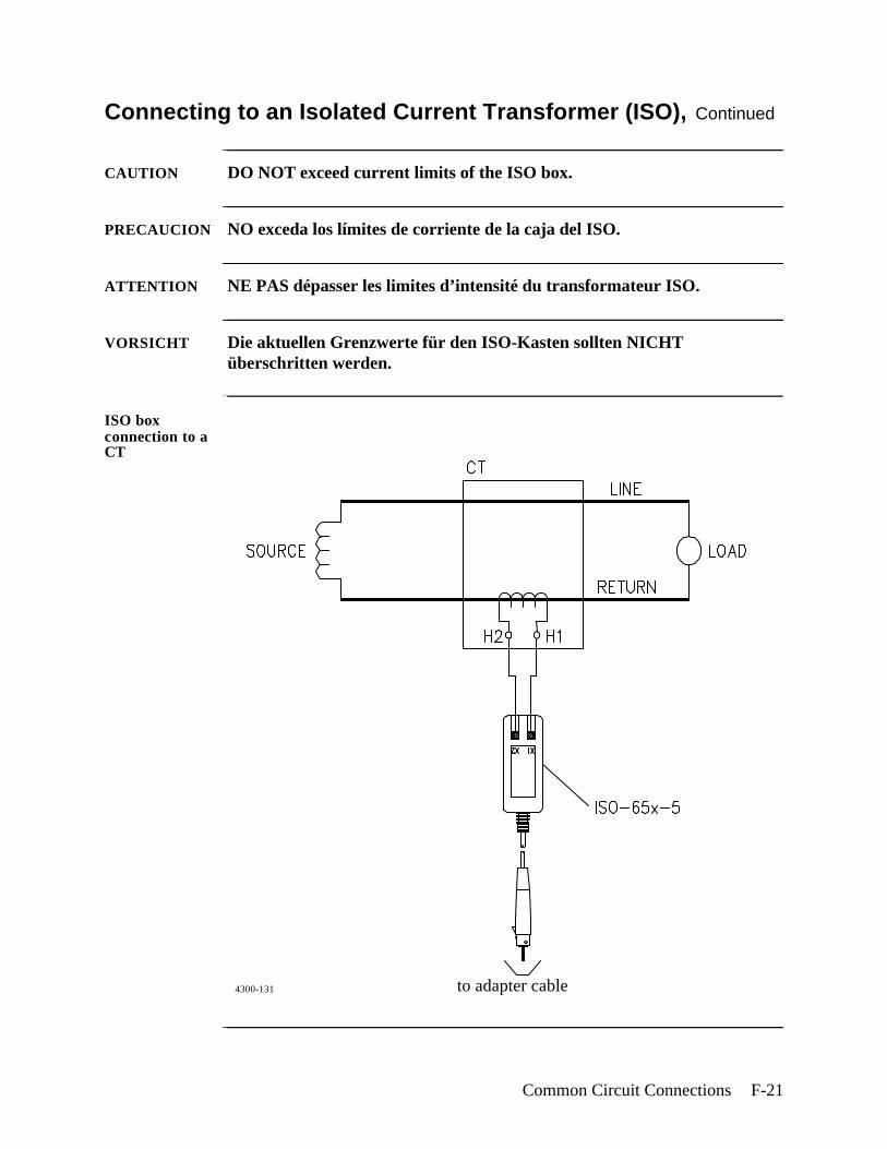
Common Circuit Connections F-21
Connecting to an Isolated Current Transformer (ISO), Continued
CAUTION DO NOT exceed current limits of the ISO box.
PRECAUCION NO exceda los límites de corriente de la caja del ISO.
ATTENTION NE PAS dépasser les limites d’intensité du transformateur ISO.
VORSICHT Die aktuellen Grenzwerte für den ISO-Kasten sollten NICHT überschritten werden.
ISO box connection to a CT
to adapter cable4300-131

F-22 4300-PQLite Operator’s Manual
PQLite Menu Structure G-1
Appendix G
PQLite Menu Structure
Overview
Menu description
The menu structure for the PQLite TASKCard is shown on the following pages. The menu structure is shown with Scope Mode as the leading element. This was done since Scope Mode appears as the first display screen following power up.
Menu structure aids
At the bottom of all screens are function keys which, when selected, permit further selection of multiple functions. The Menu Structure contains a listing of the important functions selectable under a function key. Scanning the listing under a major function can help you find other related functions and ways to access it.
In this appendix The following menus are shown in this appendix.
Topic See Page
Scope/Meter Mode Menu G-2
View Data Menu G-3
Setup Menu G-4
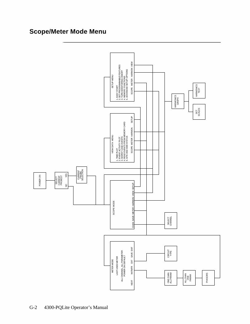
G-2 4300-PQLite Operator’s Manual
Scope/Meter Mode Menu
ME
TER
MO
DE
LAS
T U
SE
D M
ET
ER
ALL
CH
AN
NE
L, A
LL P
AR
AM
ET
ER
PO
WE
R O
N D
EF
AU
LT
NE
XT
N
XTM
TR
CK
T
SA
VE
EX
IT
VIE
W D
AT
A M
EN
U
1. T
IME
PLO
T2.
EV
EN
T A
CT
IVIT
Y P
LOT
3. W
OR
ST
CA
SE
EV
EN
TS
4. R
EA
D E
VE
NT
S F
RO
M M
EM
OR
Y C
AR
D5.
SIT
E A
ND
430
0 S
TA
TU
S
SC
OP
E M
ET
ER
HA
RM
ON
SE
TU
P
S
ET
UP
ME
NU
1. E
AS
Y S
TA
RT
2. S
ET
PR
OG
RA
MM
AB
LE F
EA
TU
RE
S3.
TU
RN
MO
NIT
OR
ING
ON
/OF
F4.
ME
MO
RY
FU
NC
TIO
NS
5. A
DV
AN
CE
D S
ET
UP
OP
TIO
NS
S
CO
PE
M
ET
ER
H
AR
MO
N V
IEW
ALL
CH
AN
ON
EP
AR
AM
PH
AS
OR
S
ON
E C
HA
NA
LL P
AR
AM
HA
RM
ON
ICS
GR
AP
H
SE
TS
CA
LES
HA
RM
ON
ICS
TE
XT
SE
LEC
TC
HA
NN
EL
SC
OP
E M
OD
E
CH
AN
SA
VE
ME
TE
R H
AR
MO
N V
IEW
SE
TU
P
CIR
CU
ITT
YP
E
PO
WE
R O
N
SE
LEC
TC
UR
RE
NT
PR
OB
ES
?
NO
YE
S
CU
RR
EN
TP
RO
BE
SE
LEC
TIO
N
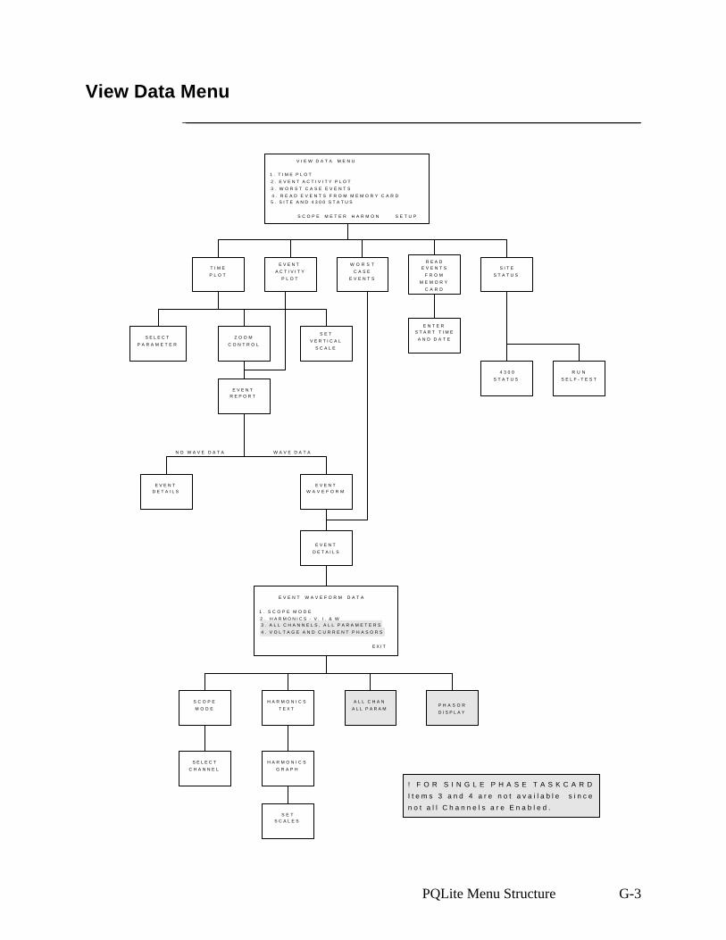
PQLite Menu Structure G-3
View Data Menu
4300-101
V I E W D A T A M E N U
1 . T I M E P L O T
2 . E V E N T A C T I V I T Y P L O T
3 . W O R S T C A S E E V E N T S
4 . R E A D E V E N T S F R O M M E M O R Y C A R D5 . S I T E A N D 4 3 0 0 S T A T U S
S C O P E M E T E R H A R M O N S E T U P
T I M E
P L O T
Z O O M
C O N T R O L
E V E N TR E P O R T
W O R S T
C A S E
E V E N T S
E V E N T
A C T I V I T Y
P L O T
S E L E C T
P A R A M E T E R
S E T
V E R T I C A L
S C A L E
R E A DE V E N T S
F R O M
M E M O R Y
C A R D
E N T E RS T A R T T I M E
A N D D A T E
S I T E
S T A T U S
4 3 0 0
S T A T U S
R U N
S E L F - T E S T
E V E N T W A V E F O R M D A T A
1 . S C O P E M O D E
2 . H A R M O N I C S - V , I , & W3 . A L L C H A N N E L S , A L L P A R A M E T E R S
4 . V O L T A G E A N D C U R R E N T P H A S O R S
E X I T
S C O P E
M O D EP H A S O R
D I S P L A Y
H A R M O N I C S
T E X T
A L L C H A N
A L L P A R A M
S E L E C T
C H A N N E L
H A R M O N I C S
G R A P H
S E TS C A L E S
E V E N TW A V E F O R M
E V E N T
D E T A I L S
E V E N TD E T A I L S
W A V E D A T AN O W A V E D A T A
! F O R S I N G L E P H A S E T A S K C A R D
I t e m s 3 a n d 4 a r e n o t a v a i l a b l e s i n c e
n o t a l l C h a n n e l s a r e E n a b l e d .
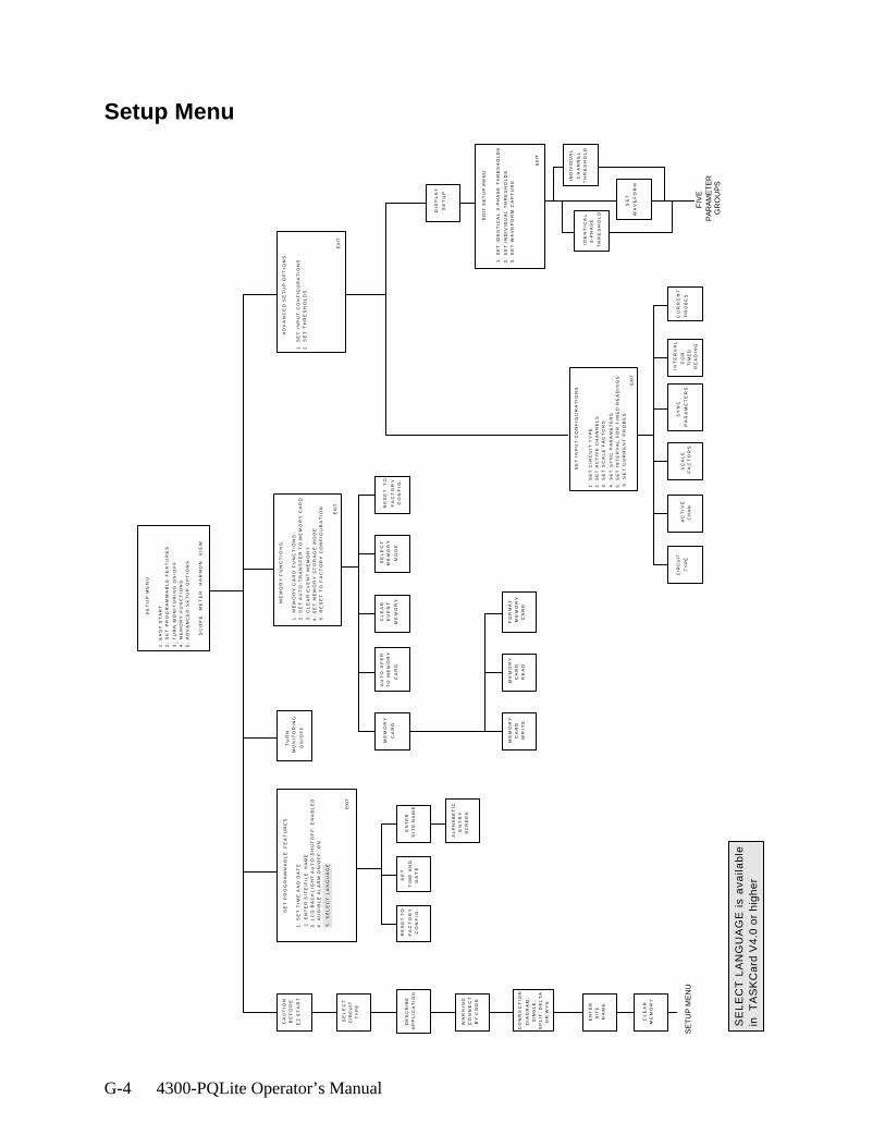
G-4 4300-PQLite Operator’s Manual
Setup Menu
E
DIT
SE
TU
P M
EN
U
1.
SE
T I
DE
NT
ICA
L 3
-PH
AS
E T
HR
ES
HO
LD
S
2.
SE
T I
ND
IVID
UA
L T
HR
ES
HO
LD
S
3.
SE
T W
AV
EF
OR
M C
AP
TU
RE
E
XIT
DIS
PL
AY
SE
TU
P
IDE
NT
ICA
L
3-P
HA
SE
TH
RE
SH
OL
D
IND
IVID
UA
L
CH
AN
NE
L
TH
RE
SH
OL
D
INT
ER
VA
L
FO
R
TIM
ED
RE
AD
ING
SC
AL
E
FA
CT
OR
S
SY
NC
PA
RA
ME
TE
RS
SE
T
WA
VE
FO
RM
FIV
EP
AR
AM
ET
ER
GR
OU
PS
S
ET
IN
PU
T C
ON
FIG
UR
AT
ION
S
1.
SE
T C
IRC
UIT
TY
PE
2.
SE
T A
CT
IVE
CH
AN
NE
LS
3.
SE
T S
CA
LE
FA
CT
OR
S
4.
SE
T S
YN
C P
AR
AM
ET
ER
S
5.
SE
T I
NT
ER
VA
L F
OR
TIM
ED
RE
AD
ING
S
6.
SE
T C
UR
RE
NT
PR
OB
ES
E
XIT
AC
TIV
E
CH
AN
SE
TU
P M
EN
U
1.
EA
SY
ST
AR
T
2.
SE
T P
RO
GR
AM
MA
BL
E F
EA
TU
RE
S
3.
TU
RN
MO
NIT
OR
ING
ON
/OF
F
4.
ME
MO
RY
FU
NC
TIO
NS
5.
AD
VA
NC
ED
SE
TU
P O
PT
ION
S
SC
OP
E
ME
TE
R
HA
RM
ON
V
IEW
A
DV
AN
CE
D S
ET
UP
OP
TIO
NS
1.
SE
T I
NP
UT
CO
NF
IGU
RA
TIO
NS
2.
SE
T T
HR
ES
HO
LD
S
EX
IT
CA
UT
ION
BE
FO
RE
EZ
ST
AR
T
SE
LE
CT
CIR
CU
IT
TY
PE
DE
SC
RIB
E
AP
PL
ICA
TIO
N
WA
RN
ING
CO
NN
EC
T
BY
CO
DE
EN
TE
R
SIT
E
NA
ME
CL
EA
R
ME
MO
RY
CO
NN
EC
TIO
N
DIA
GR
AM
:
SIN
GL
E,
SP
LIT
, D
EL
TA
,
OR
WY
E
EN
TE
R
SIT
E N
AM
E
SE
T
TIM
E A
ND
DA
TE
AL
PH
AB
ET
IC
EN
TR
Y
SC
RE
EN
TU
RN
MO
NIT
OR
ING
ON
/OF
F
M
EM
OR
Y F
UN
CT
ION
S
1.
ME
MO
RY
CA
RD
FU
NC
TIO
NS
2.
SE
T A
UT
O-T
RA
NS
FE
R T
O M
EM
OR
Y C
AR
D
3.
CL
EA
R E
VE
NT
ME
MO
RY
4.
SE
T M
EM
OR
Y S
TO
RA
GE
MO
DE
5.
RE
SE
T T
O F
AC
TO
RY
CO
NF
IGU
RA
TIO
N
E
XIT
CL
EA
R
EV
EN
T
ME
MO
RY
AU
TO
-XF
ER
TO
ME
MO
RY
CA
RD
SE
LE
CT
ME
MO
RY
MO
DE
RE
SE
T T
O
FA
CT
OR
Y
CO
NF
IG.
ME
MO
RY
CA
RD
ME
MO
RY
CA
RD
WR
ITE
ME
MO
RY
CA
RD
RE
AD
FO
RM
AT
ME
MO
RY
CA
RD
CIR
CU
IT
TY
PE
SE
T P
RO
GR
AM
MA
BL
E
FE
AT
UR
ES
1.
SE
T T
IME
AN
D D
AT
E
2.
EN
TE
R S
ITE
/FIL
E
NA
ME
3.
LC
D B
AC
KL
IGH
T A
UT
O-S
HU
TO
FF
: E
NA
BL
ED
5.
SE
LE
CT
LA
NG
UA
GE
4.
AU
DIB
LE
AL
AR
M O
N/O
FF
: O
N
E
XIT
CU
RR
EN
T
PR
OB
ES
RE
SE
T
TO
FA
CT
OR
Y
CO
NF
IG.
SE
TU
P M
EN
U
SE
LE
CT
LA
NG
UA
GE
is
ava
ilab
lein
T
AS
KC
ard
V4
.0 o
r h
igh
er
4300-PQLite Operator’s Manual Index-1
Numerics
4300connecting to an ac power source 3-2installing TASKCard 3-3operational description 1-8optional accessories A-3physical description 1-6rear, right, and left panels 2-4resetting to factory configuration 5-8standard accessories 1-6top and front panels 2-2turning on monitoring 6-30
4300 Status Screen 5-12658/4300 Current Probe Adapter Cable A-3
A
AC Power Source 3-2Active Channels Screen 6-6Alarm
turning on and off 5-6Alphabetic Entry Screen 5-3, 6-25Apparent Power
formula B-7viewing 4-4
Auto-Transfer to Memory Card Screen 7-4
B
Battery Packreplacement C-5safety precautions C-3specifications C-2
C
Calibration 1-7Channel Selection Screen 4-2Circuit Type
selecting 6-8Circuit Type Screen 4-4, 6-8
Index
Index-2 4300-PQLite Operator’s Manual
Clear Event Memory Screen 5-7CompactFlash Card, see Memory CardCurrent
ABC totals formula B-6viewing 4-4
Current Channelsspecifications B-4turning on and off 6-6
Current Connectionscurrent probe 3-14current transformer (CT) F-16guidelines 3-17isolated current transformer (ISO) F-18safety precautions 3-14verifying F-4
Current Phasors 4-7Current Probes
connecting 3-14selecting 3-17specifications for TR2500 B-8
Current Probes Screen 3-17Current Transformers
connecting F-16safety precautions F-16types of F-17
D
Datesetting 5-5
Default Settings, see factory configurationDelta
floating, connection diagram F-10high-leg, connection diagram F-13one leg grounded connection diagram F-10open leg, connection diagram F-12
Describe Application Screen 6-4Display, see LCDDRAN-LINKTM Application, see EventsDRAN-VIEW® Application, see Events
Index, Continued
4300-PQLite Operator’s Manual Index-3
E
Easy Startdescription 1-8, 6-3monitoring combinations 6-4parameter thresholds 6-5using 6-3
Easy Start Screen 6-4Edit Setup Menu 6-21, 6-22Enter Site/File Name Screen 5-2Error Messages
descriptions E-4priority E-2
Event Activity Plot Screen 8-17Event Descriptions
miscellaneous events 8-21return to normal events 8-21threshold events 8-20
Event DetailsIEEE classifications 8-26
Event Details Screen 8-25Event Report Screen 8-19Event Waveform Data Screen 8-30Event Waveform Screen 8-29Event Waveforms
3-cycle waveform definition 8-28analysis of 8-30viewing 8-28, 8-34, 8-35
Eventsdescription 1-9downloading from 4300 to a computer 8-32downloading from internal memory 8-37downloading from memory card 8-37using DRAN-LINKTM to download data 1-1, 8-1, 8-34using DRAN-VIEW® to view data 8-1, 8-34, 8-35viewing complete event report 8-19viewing worst case 8-23
Index, Continued
Index-4 4300-PQLite Operator’s Manual
F
Factory Configurationdefinition 5-8list of settings 5-8resetting unit to 5-10
Format Memory Card Screen 7-6Frequency
viewing 4-4Frequency Synchronization
definition 6-13entering internal frequency 6-15External CH D 6-13loss of 6-13stable signal 6-14
H
Handbook for Electrical Energy Management A-5Handbook for Power Quality Analysis A-5Harmonics
viewing 4-8Heavy Duty Cable Set A-5
I
IEEE Classifications 8-26Input Channels
definition 6-6Interval for Timed Readings Screen 6-17Isolated Current Transformers (ISO boxes) F-18
applications F-19connecting F-18safety precautions F-18
L
Languageselect 1-1, 5-6selection screen 1-2, 5-6
LCDbacklight auto-shutoff 5-6specifications B-3
Index, Continued
4300-PQLite Operator’s Manual Index-5
M
Measurement Cable Set 3-10Memory
clearing 5-7Memory Card
automatically saving data to 7-3CompactFlash Card 1-10, A-9description 1-9, 1-10, A-3, A-6manually saving data to 7-5SRAM Card 1-9, A-6
Memory Card Function Screen 7-5Memory Card Readers
CompactFlash Card Reader A-3, A-6SRAM Card Reader A-3, A-6
Memory Storage Mode Screen 7-2Menu Structure G-2Messages
descriptions E-3priority E-2
Meter Modeavailable parameters 4-6description 1-8viewing 4-4, 4-5
Monitoringturning on 6-30
Monitoring Setupchanging setup name 6-25definition 6-1description 1-8
O
Optional Accessories A-3
P
Parameter Thresholdsenabling/disabling a parameter 6-24editing 6-19, 6-20, 6-21, 6-22, 6-23, 6-24entering a harmonic number 6-26ranges 6-19
Index, Continued
Index-6 4300-PQLite Operator’s Manual
saving 6-26Phasor Screen 4-7, F-5, F-6Potential Transformers
connecting F-14definition F-14scale factor F-15
Power Factorformula B-7viewing 4-4
Power Measurementsdelta, one leg grounded F-10delta, open leg F-12floating delta F-10high-leg delta F-13open leg delta F-12single phase F-7split phase F-8
R
Reactive Powerformula B-7viewing 4-4
Read Data From Memory Card Screen 8-8Read Events From Memory Card Screen 8-5Replaceable Parts List D-1Reset to Factory Configuration Screen 5-10Reusable Shipping Container A-6Run Self-Test Screen 5-13
S
Scale Factorsdefinition 6-10entering 6-11examples 6-10for Dranetz equipment 6-10range 6-11when to use 6-10
Scale Factors Screen 6-11Scope Mode
description 1-8timeout 4-3
Index, Continued

4300-PQLite Operator’s Manual Index-7
viewing 4-2Select Parameter to Plot Screen 8-12Self-Test
running 5-13Set Identical 3-Phase Thresholds Screen 6-22Set Individual Channel Thresholds Screen 6-23Set Programmable Features Menu 5-6Set Time and Date Screen 5-4Set Vertical Scale Screen 8-15Setup Menu Screen 6-29Setup Name
changing 6-25Single Phase
connection diagram F-7TASKCard description 1-3, A-7
Site Nameentering 5-2
Site Status Screen 5-11Soft Carrying Case A-6Spare Parts D-1Specifications
computed parameters B-6general B-2interfaces B-3measured parameters B-4TR2500 current probe B-8
Split Phaseconnection diagram F-8
Standard Accessories 1-6measurement cable set 3-10
Starting Date and Time Screen 8-6Sync Parameters Screen 6-16
T
TASKCarderror messages when loading 3-6, E-4installation 3-3optional A-7Single Phase description 1-3, A-7Three Phase description 1-3, A-7
Three PhaseTASKCard description 1-3, A-7
Index, Continued

Index-8 4300-PQLite Operator’s Manual
Threshold Screen 6-21Time
setting 5-4Time Plot Screen 8-11
changing vertical scale 8-15selecting parameter to plot 8-12using horizontal zoom 8-13
Turn Monitoring On/Off Screen 6-30
V
VoltageABC totals formula B-6viewing 4-4
Voltage and Current Harmonics Graph Screen 4-8Voltage and Current Harmonics Text Screen 4-9Voltage Channels
specifications B-4turning on and off 6-6
Voltage Connectionsneutral to ground example 3-13potential transformers F-14single phase example 3-12verifying F-4voltage measurement cables 3-11
Voltage Phasors 4-6Volt-Amps
formula B-7viewing 4-4
Volt-Amps Reactiveformula B-7viewing 4-4
W
Wattsformula B-6viewing 4-4
Waveform Capturechanging a setting 6-28combinations 6-27definition 6-27Select Wave key 6-17
Index, Continued

4300-PQLite Operator’s Manual Index-9
Waveform Capture Screen 6-27, 6-28Waveforms, see event waveformsWorst Case Events Screen 8-23Write Data to Memory Card Screen 7-6
Z
Zoom Screen 8-13