power quality enhancement using interline dynamic...
TRANSCRIPT

Power Quality Enhancement Using InterlineDynamic Voltage Restorer with a FuzzyLogic ControllerP. Sivaperumal1, S.S. Dash2 and Adithya Rahul S.V.3
ABSTRACT
Custom power devices like DVR, DSTATCOM, UPQC are used for mitigating power quality problems like voltagesag , voltage swell, interruptions etc. at the distribution side.DVR has been used in these system to performance itsfast dynamic response and provide low harmonic of the voltage restorer.The Dynamic Voltage Restorer (DVR) isan effective series compensation device due to its fast response. However the amount of energy it requires as inputfor mitigating a power quality problem depends upon the problem duration. For longer durations greater energy isrequired. This limits the application of DVR. To overcome this situation an Interline Dynamic VoltageRestorer(IDVR)that contains two or more DVR’s of different feeders is proposed. This paper presents a simulationmodel of the IDVR which utilizes a voltage fed switched coupled inductor inverter (VFSCII) instead of a conventionalVSI. The phase advance angle of the load during fault condition is taken for generating the reference voltage. Thisvoltage is compared with the load voltage using a fuzzy logic controller to generate pulses required for triggeringthe VFSCII.
Keywords: Interline Dynamic Voltage Restorer, Voltage Fed-Switched Coupled Inductor Inverter, Fuzzy logic,Power devices
1. INTRODUCTION
Power quality is of important concern at both the transmission side and distribution side. To maintain thepower quality,flexible ac transmission system (FACTS) devices are used at the transmission side. Butthe root cause of the power quality problems like voltage sag, voltage swell, interruptions etc. is due tothe usage of ac drives, welding machines, electronic devices at etc. at the distribution side. Thereforeinstalling devices that could maintain the quality of power at the distribution side itself would be moresatisfactory[6].
Custom power devices are the modified form of FACTS devices that are used for maintain powerquality at distribution side. DVR, DSTATCOM, UPQC are some of the commonly used custom powerdevices. Dynamic Voltage Regulator (DVR) is proven to the most efficient series compensation devicebecause of its fast response nature[9]. It utilizes the energy from external sources like batteries orfrom DC link capacitors and converts into a three phase voltage which is injected in series to thedistribution feeder lines [1],[6]. The mitigation percentage mainly depends upon the amount of energyavailable at its input. To mitigate a longer duration fault, more amount of energy is required. Thislimits the application of DVR. To overcome this limitation an interline dynamic voltage regulator(IDVR) is proposed. An IDVR consists of two or more DVRs of different feeders that are connected toa common DC link. When a fault occurs on one feeder, the DVRs of other feeders operate to replenishthe DC link capacitors[3],[4]. The DVR of the faulted feeder utilizes the energy from the DC link formitigating the fault on the feeder.
1,2,3 Department of Electrical and Electronics Engineering, SRM University, Kattankulathur, Chennai, Emails: [email protected], [email protected], [email protected]
I J C T A, 9(15), 2016, pp. 7673-7680© International Science Press

7674 P. Sivaperumal, S.S. Dash and Adithya Rahul S.V.
This paper presents a simulation model of an IDVR consisting of only two feeders. It implements avoltage fed switched coupled inductor inverter strategy instead of a normal VSI [2]. The reference voltagesare generated considering the phase advance angle that occurs during the fault. This voltage is comparedwith the load voltage using a fuzzy logic controller[5], [7]. The controller generates the pulses required fortriggering the VFSCII.
2. INTERLINE DYANAMIC VOLTAGE RESTORER
An interline dynamic voltage restorer is similar to the interline power flow controller (IPFC) conceptwhere the static synchronous series compensators (SSSC) of different transmission lines are commonlyconnected to a DC link. An IDVR consists of two or more DVRs connected to a DC link. Each DVRconsists of an injection transformer, a filter and an inverter to which the DC link capacitor is connected.The filter is used to eliminate the unnecessary harmonic content present at the output of inverter. Aschematic diagram of an IDVR with VFSCII and fuzzy control is given in Fig 1.where the two DVRs areconnected across a common DC link. Here a fuzzy logic control strategy is implemented for triggeringthe inverter. The displacement angle or phase advance angle of the voltage input during fault is takeninto consideration for giving the reference voltage input.During normal conditions each of the feedersoperateindependently.
When a fault occurs at any of the feeders, the power flow between two DVRs through a DC linkcapacitor takes place. The DVR of the faulted feeder then operates in compensating mode to mitigate theproblem [3][4]. The control logic for the triggering of inverters is done by considering the reference voltageacross the DC link capacitor and the load voltage with its phase angle jump.
3. VOLTAGE FED SWITCHED COUPLED INDUCTOR INVERTER
The voltage fed switched coupled inductor inverter(VFSCII) is used instead of the conventional VSI’s forits high voltage buck boost capability. It has the same principle of Z source inverter (ZSI) but requires onlyhalf the no of passive components used in ZSIand along with a greater shoot through capability for thesame voltage gain [2]. It contains two modes of operation namely shoot through state and non-shoot throughstate. Shoot through means switching of the same leg thyristors during the voltage zero crossing instancesleading to a short circuit condition and in turn can damage the inverter. To avoid this VFSCII consists of adiode and a mutual coupled inductor with a capacitor connected to one of the winding.
Figure 1: Schematic Diagram of the proposed interline dynamic voltage restorer.

Power Quality Enhancement Using Interline Dynamic Voltage Restorer... 7675
Under normal conditions current flows from the source, charging the inductors and returns through thethyristors of the inverter. During this period the capacitor is also charged by the inductor winding L2.During the shoot through period the diode is switched off and no current flows from source. The chargedcapacitor discharges and makes the L2 winding to charge with the current flowing through the thyristorsagain. The total energy in the inductors during the switching period is to be maintained constant.
4. CONTROL STRATEGY FOR IDVR
4.1. Reference Voltage Generation
When the fault occurs at the second feeder, the converter of the first feeder is responsible for energizing theDC capacitor by transferring some amount of active power from the feeder 1 to the capacitor. The powerexchange P
xg is determined by the load voltage advanced angle �.
Figure 2: VFSCII during normal state.
Figure 3: VFSCII during shoot through state.
Figure 4 : Phasor Diagram of Feeder-1

7676 P. Sivaperumal, S.S. Dash and Adithya Rahul S.V.
1 1 1 1 1 13 cos( ) 3 cosxgP V I V I (1)
For the case of maximum power exchange �1 = �, then P
xg becomes
1 1(1 cos )xgrefP S (2)
This power is taken as the reference power exchange. Now the net reference voltage for the input of thefuzzy controller is obtained by considering the load advanced angle ��which is calculated using the activecurrent at the DC capacitor i
dact. This is calculated by considering the direct axis component that is in phase
with the supply voltage V1d
. The net exchange power is divided with V1d
to obtain idact
. This is divided withthe measured peak value of the load current i
p1.
( )*( / )xg dcref dc p iP V V K K s (3)
xgnet xg xgrefP P P (4)
1(2 / 3)*( ) /dact xgnet di P V (5)
11 1cos ( / )dact pi i (6)
Where Vdcref
and Vdc
are the reference and actual voltages of the DC link capacitor.
Now the d and q components of the reference voltage is obtained by,
1 1 *cosdref mV V (7)
1 1 *sinqref mV V (8)
The same equations are used for generating the reference voltage at faulted feeder except the power atthe capacitor is also taken into consideration.
2
2 2 2 0.5xgnet xg xgref dcP P P CV (9)
Where C is the DC link capacitor value.
4.2. Fuzzy Logic Controlling Strategy
The d and q components from the load voltages are taken and are subtracted from their respective referencevoltages generated considering the load advance angles [5]. This gives the error signal for each component. The
Figure 5 : The membership functions for error, change in error and output signal.

Power Quality Enhancement Using Interline Dynamic Voltage Restorer... 7677
change in error signal is obtained by differentiating the error signal. The error and change in error is given asinputs to the fuzzy logic controller. Seven triangular membership functions are considered for each input and theoutput is also assigned with seven triangular membership functions. Centroid method is used for defuzzification.
5. SIMULATION RESULTS
The simulation for a three phase IDVR is carried out between two feeders each consisting of 11 KV inMATLAB-Simulink is shown in Fig 5. The corresponding DVRs are connected between the source busand load bus. The DC link capacitor value is chosen as 750µF. Different fault conditions are considered andthe output results are shown.
Table 1Rule base for fuzzy logic controller.
Figure 6: Simulink Model of IDVR.

7678 P. Sivaperumal, S.S. Dash and Adithya Rahul S.V.
5.1. During Voltage Interruption
A voltage interruption is created at the Feeder 2 by introducing a balanced 3 phase fault with fault andground impedance values as 0.001� during the instant 0.4 sec to 0.6 sec. The waveforms for the outputvoltage of feeder 2 without and with compensation by IDVR are shown in the Fig 6 below.
5.2. During Voltage Sag
Voltagesag is created at the Feeder 2 by introducing a balanced 3 phase fault with fault and ground impedancevalues as 0.075� and 0.001� during the instant 0.4 sec to 0.6 sec. The waveform for the output voltage offeeder 2 without and with compensation by IDVR is shown in the Fig. 7 below.
Table 2Parameter details of the IDVR
S. No Parameters Feeder 1 Feeder 2
1. Source voltage 11 KV 11 KV2. Load Resistance per phase 1 ohms 1 ohms3. Load Inductance per phase 0.01926 H 0.01926 H4. Injection Transformer (Line to Line) HV Side-11 KV HV Side-11 KV
LV Side-5 KV LV Side- 5 KV5. Filter inductance per phase 10 mH 10 mH6. Filter Capacitance per phase 750 µF 750 µF
Figure 7: Line voltages of Feeder 2 during an interruption without and with compensation.
Figure 8: Line voltages of Feeder 2 during a voltage sag without and with compensation.
Power Quality Enhancement Using Interline Dynamic Voltage Restorer... 7679
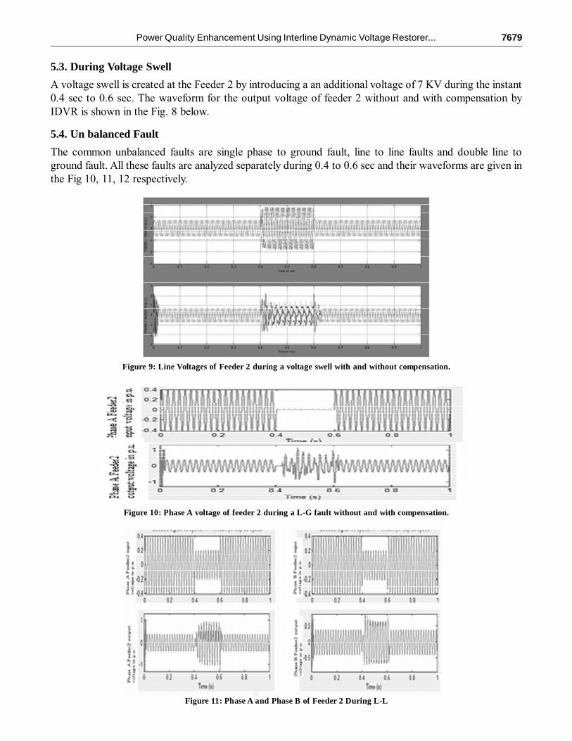
5.3. During Voltage Swell
A voltage swell is created at the Feeder 2 by introducing a an additional voltage of 7 KV during the instant0.4 sec to 0.6 sec. The waveform for the output voltage of feeder 2 without and with compensation byIDVR is shown in the Fig. 8 below.
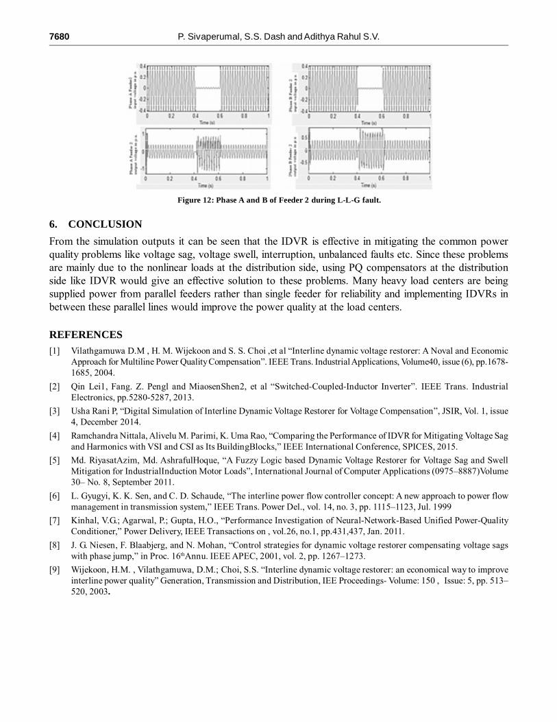
5.4. Un balanced Fault
The common unbalanced faults are single phase to ground fault, line to line faults and double line toground fault. All these faults are analyzed separately during 0.4 to 0.6 sec and their waveforms are given inthe Fig 10, 11, 12 respectively.
Figure 9: Line Voltages of Feeder 2 during a voltage swell with and without compensation.
Figure 10: Phase A voltage of feeder 2 during a L-G fault without and with compensation.
Figure 11: Phase A and Phase B of Feeder 2 During L-L
7680 P. Sivaperumal, S.S. Dash and Adithya Rahul S.V.
6. CONCLUSION
From the simulation outputs it can be seen that the IDVR is effective in mitigating the common powerquality problems like voltage sag, voltage swell, interruption, unbalanced faults etc. Since these problemsare mainly due to the nonlinear loads at the distribution side, using PQ compensators at the distributionside like IDVR would give an effective solution to these problems. Many heavy load centers are beingsupplied power from parallel feeders rather than single feeder for reliability and implementing IDVRs inbetween these parallel lines would improve the power quality at the load centers.
REFERENCES[1] Vilathgamuwa D.M , H. M. Wijekoon and S. S. Choi ,et al “Interline dynamic voltage restorer: A Noval and Economic
Approach for Multiline Power Quality Compensation”. IEEE Trans. Industrial Applications, Volume40, issue (6), pp.1678-1685, 2004.
[2] Qin Lei1, Fang. Z. Pengl and MiaosenShen2, et al “Switched-Coupled-Inductor Inverter”. IEEE Trans. IndustrialElectronics, pp.5280-5287, 2013.
[3] Usha Rani P, “Digital Simulation of Interline Dynamic Voltage Restorer for Voltage Compensation”, JSIR, Vol. 1, issue4, December 2014.
[4] Ramchandra Nittala, Alivelu M. Parimi, K. Uma Rao, “Comparing the Performance of IDVR for Mitigating Voltage Sagand Harmonics with VSI and CSI as Its BuildingBlocks,” IEEE International Conference, SPICES, 2015.
[5] Md. RiyasatAzim, Md. AshrafulHoque, “A Fuzzy Logic based Dynamic Voltage Restorer for Voltage Sag and SwellMitigation for IndustrialInduction Motor Loads”, International Journal of Computer Applications (0975–8887)Volume30– No. 8, September 2011.
[6] L. Gyugyi, K. K. Sen, and C. D. Schaude, “The interline power flow controller concept: A new approach to power flowmanagement in transmission system,” IEEE Trans. Power Del., vol. 14, no. 3, pp. 1115–1123, Jul. 1999
[7] Kinhal, V.G.; Agarwal, P.; Gupta, H.O., “Performance Investigation of Neural-Network-Based Unified Power-QualityConditioner,” Power Delivery, IEEE Transactions on , vol.26, no.1, pp.431,437, Jan. 2011.
[8] J. G. Niesen, F. Blaabjerg, and N. Mohan, “Control strategies for dynamic voltage restorer compensating voltage sagswith phase jump,” in Proc. 16thAnnu. IEEE APEC, 2001, vol. 2, pp. 1267–1273.
[9] Wijekoon, H.M. , Vilathgamuwa, D.M.; Choi, S.S. “Interline dynamic voltage restorer: an economical way to improveinterline power quality” Generation, Transmission and Distribution, IEE Proceedings- Volume: 150 , Issue: 5, pp. 513–520, 2003.
Figure 12: Phase A and B of Feeder 2 during L-L-G fault.