power quality problems harmonics and its...
TRANSCRIPT

POWER QUALITY PROBLEMS HARMONICS AND ITS MITIGATION
Nimai Mahapatro Hindalco Industries Limited
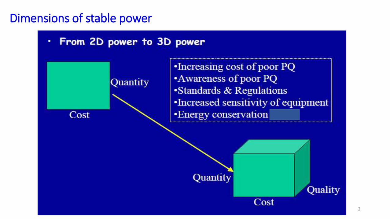
Dimensions of stable power
2
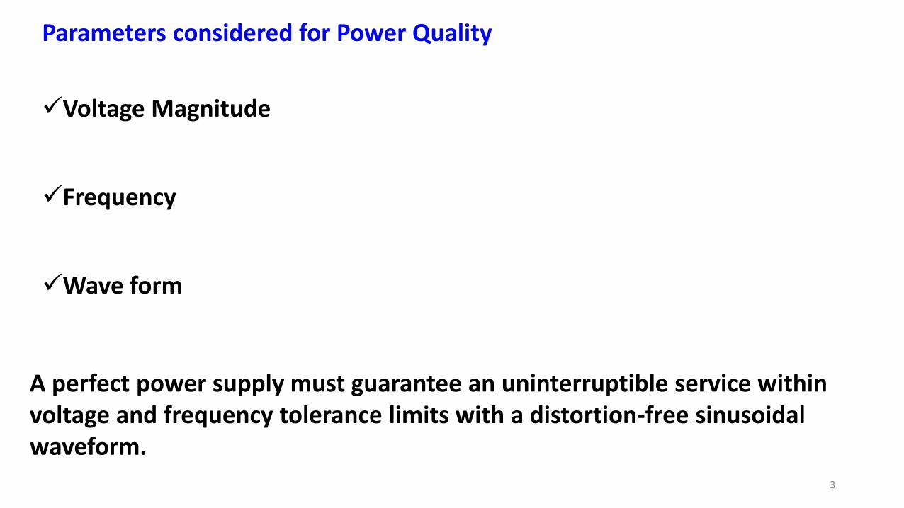
Parameters considered for Power Quality
Voltage Magnitude
Frequency
Wave form
3
A perfect power supply must guarantee an uninterruptible service within voltage and frequency tolerance limits with a distortion-free sinusoidal waveform.
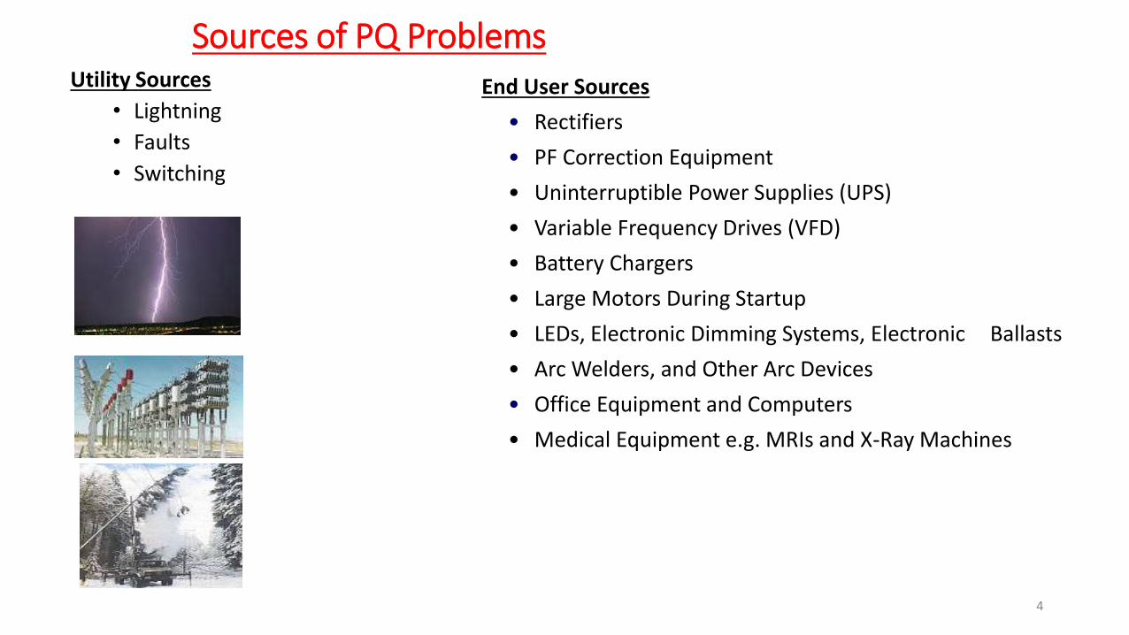
Sources of PQ Problems Utility Sources
• Lightning
• Faults
• Switching
End User Sources
• Rectifiers
• PF Correction Equipment
• Uninterruptible Power Supplies (UPS)
• Variable Frequency Drives (VFD)
• Battery Chargers
• Large Motors During Startup
• LEDs, Electronic Dimming Systems, Electronic Ballasts
• Arc Welders, and Other Arc Devices
• Office Equipment and Computers
• Medical Equipment e.g. MRIs and X-Ray Machines
4
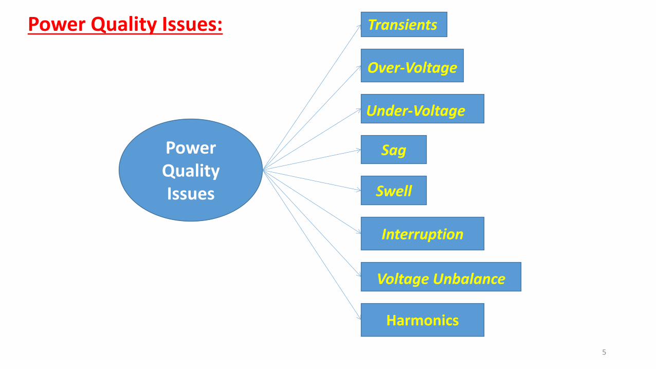
Power Quality Issues
Transients
Over-Voltage
Sag
Under-Voltage
Voltage Unbalance
Interruption
Swell
Harmonics
Power Quality Issues:
5
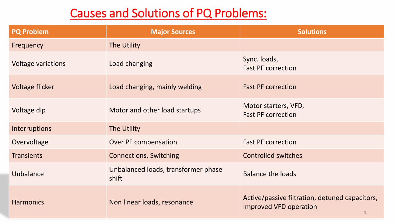
Causes and Solutions of PQ Problems:
PQ Problem Major Sources Solutions
Frequency The Utility
Voltage variations Load changing Sync. loads, Fast PF correction
Voltage flicker Load changing, mainly welding Fast PF correction
Voltage dip Motor and other load startups Motor starters, VFD, Fast PF correction
Interruptions The Utility
Overvoltage Over PF compensation Fast PF correction
Transients Connections, Switching Controlled switches
Unbalance Unbalanced loads, transformer phase shift
Balance the loads
Harmonics Non linear loads, resonance Active/passive filtration, detuned capacitors, Improved VFD operation
6
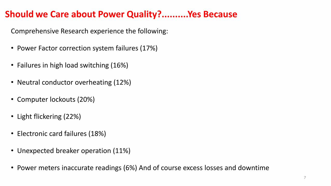
Should we Care about Power Quality?..........Yes Because
Comprehensive Research experience the following:
• Power Factor correction system failures (17%)
• Failures in high load switching (16%)
• Neutral conductor overheating (12%)
• Computer lockouts (20%)
• Light flickering (22%)
• Electronic card failures (18%)
• Unexpected breaker operation (11%)
• Power meters inaccurate readings (6%) And of course excess losses and downtime
7
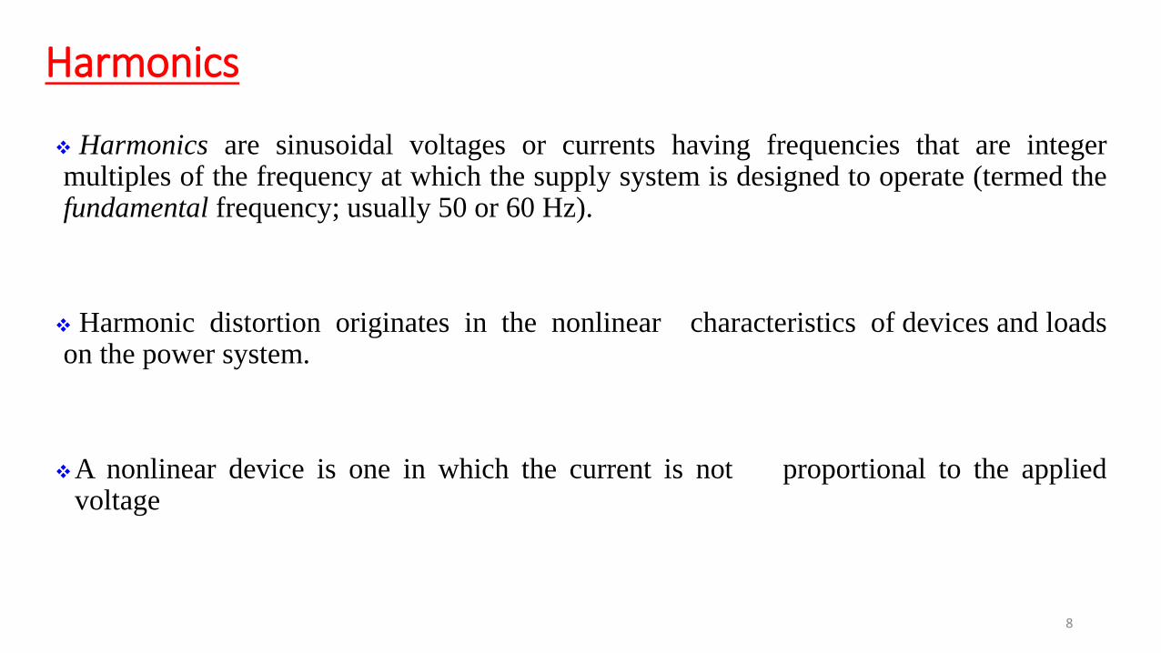
Harmonics
Harmonics are sinusoidal voltages or currents having frequencies that are integer multiples of the frequency at which the supply system is designed to operate (termed the fundamental frequency; usually 50 or 60 Hz).
Harmonic distortion originates in the nonlinear characteristics of devices and loads on the power system.
A nonlinear device is one in which the current is not proportional to the applied voltage
8
9
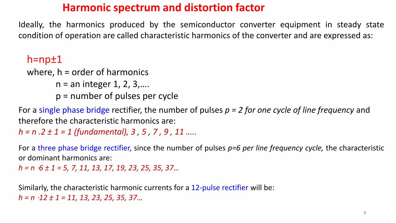
Harmonic spectrum and distortion factor
Ideally, the harmonics produced by the semiconductor converter equipment in steady state condition of operation are called characteristic harmonics of the converter and are expressed as:
h=np±1 where, h = order of harmonics n = an integer 1, 2, 3,…. p = number of pulses per cycle
For a single phase bridge rectifier, the number of pulses p = 2 for one cycle of line frequency and therefore the characteristic harmonics are: h = n .2 ± 1 = 1 (fundamental), 3 , 5 , 7 , 9 , 11 …..
For a three phase bridge rectifier, since the number of pulses p=6 per line frequency cycle, the characteristic or dominant harmonics are: h = n ⋅6 ± 1 = 5, 7, 11, 13, 17, 19, 23, 25, 35, 37… Similarly, the characteristic harmonic currents for a 12-pulse rectifier will be: h = n ⋅12 ± 1 = 11, 13, 23, 25, 35, 37…
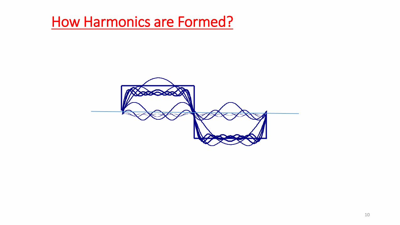
How Harmonics are Formed?
10

inverters &
high-frequency
lighting
Switched-mode
power supplies
supply impedance Variable-speed
ac/dc drive
systems
Uninterruptible
power supply
systems
11
Non Linear Loads
LED lights & Arc Furnaces
AC/DC Converters

Non-linear Load
Linear Load
3 February 2017 12 Dr.Parthasarathy/KLNCE/ WESCO-odisa
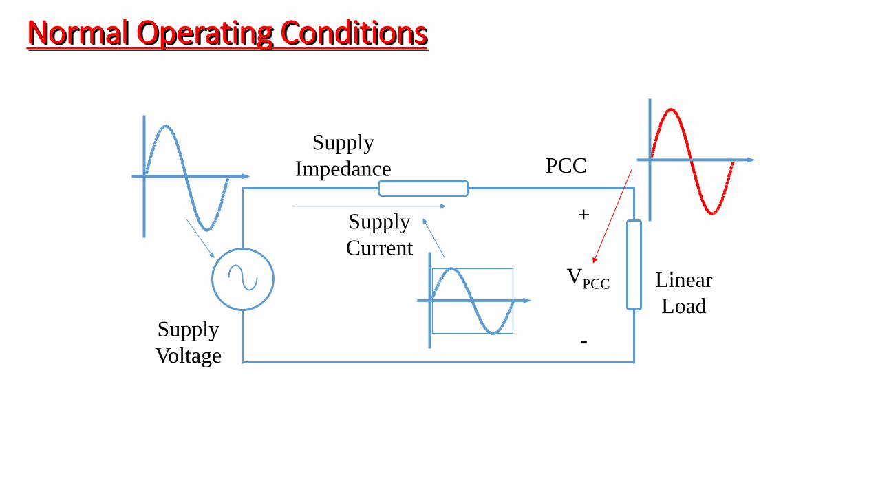
Supply
Voltage
Linear
Load
Supply
Impedance
Normal Operating Conditions
Supply
Current
PCC
VPCC
+
-
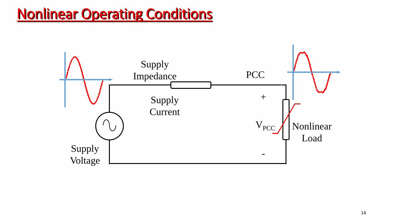
Nonlinear Operating Conditions
Supply
Voltage
Nonlinear
Load
Supply
Impedance PCC
Supply
Current
VPCC
+
-
14
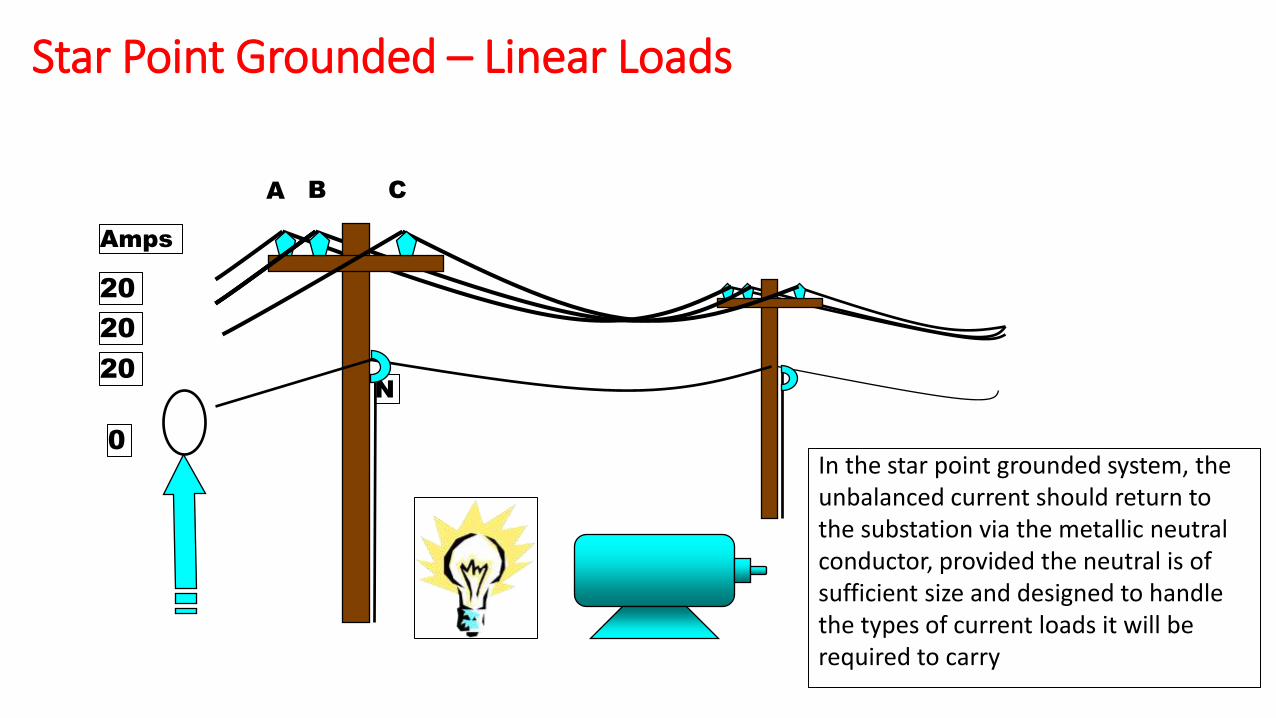
Star Point Grounded – Linear Loads
A B C
N
In the star point grounded system, the unbalanced current should return to the substation via the metallic neutral conductor, provided the neutral is of sufficient size and designed to handle the types of current loads it will be required to carry
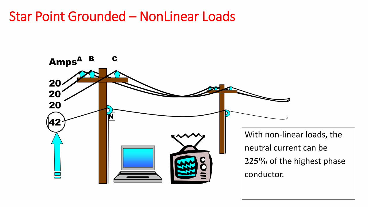
20
20
20
0
Amps
A B C
N
20
20
20
42
With non-linear loads, the
neutral current can be
225% of the highest phase
conductor.
Amps
Star Point Grounded – NonLinear Loads
A B C
N
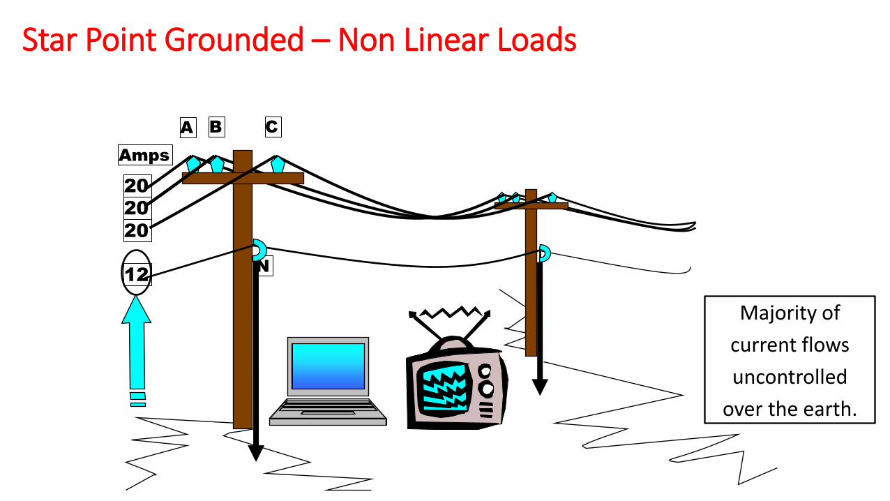
20
20
20
12
Majority of
current flows
uncontrolled
over the earth.
Amps
Star Point Grounded – Non Linear Loads

18
Effects of Harmonics Overheating of the power distribution system leading to equipment failure
Electrical equipment consume 15 % higher energy
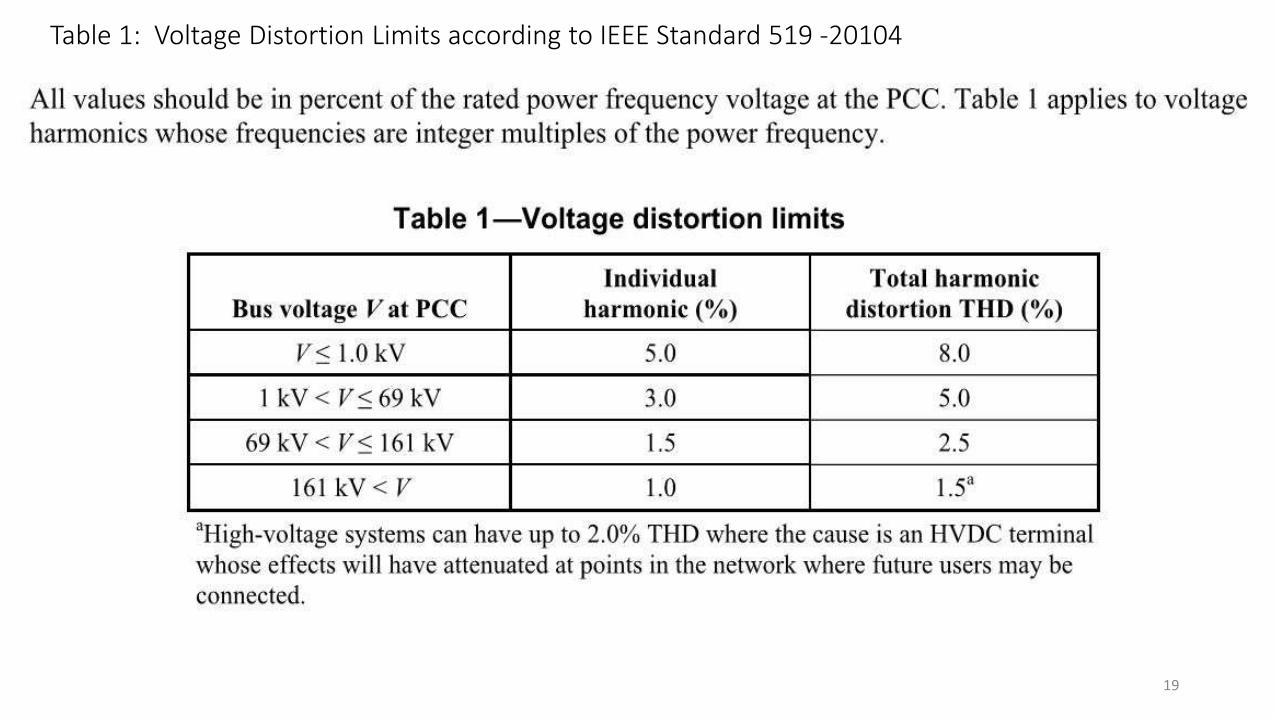
Table 1: Voltage Distortion Limits according to IEEE Standard 519 -20104
19
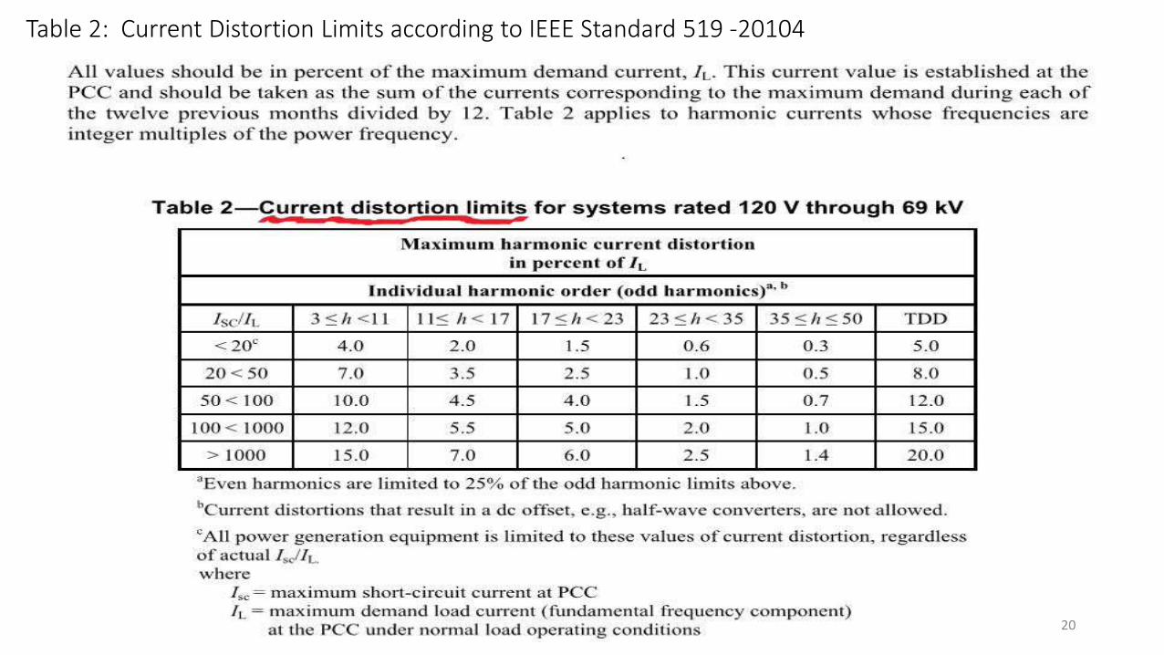
Table 2: Current Distortion Limits according to IEEE Standard 519 -20104
20
21
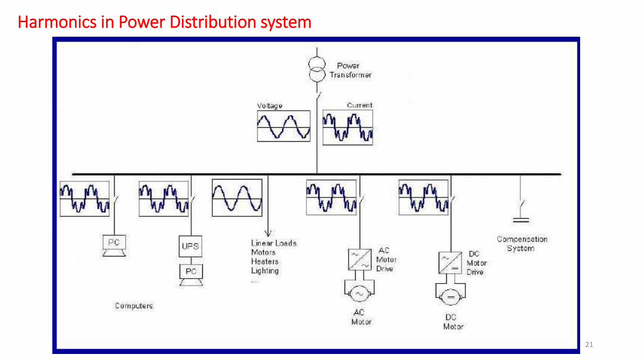
Harmonics in Power Distribution system
4 or 5 Rectifier transformers connected at different phase shifts feed the DC to pot line
Harmonics in Aluminium Smelter pot line
Effective pulses comes to either 48 or 60 and AC power feeding this DC load becomes fairly sinusoidal.
Harmonic distortion occurs at the point of coupling mainly due to
Loading and rating of each of the RT may not be uniform.
Outage of one of the RT may reduce the total number of pulses to 36 from 48
Unbalance between loading of the two secondary windings of the same RT
Usage of standby RTs for normal operations to meet the production
Grouped tap position change of one PL can change system impedance significantly shifting the resonance coinciding with one of the prevailing order of harmonics.
Changes in the high voltage network configuration can shift the resonance frequency (due to changes in system impedance).
• Multi pulse AC/DC converters with phase shifting transformers
• Installing filters on AC side
How to Eliminate Harmonics
23
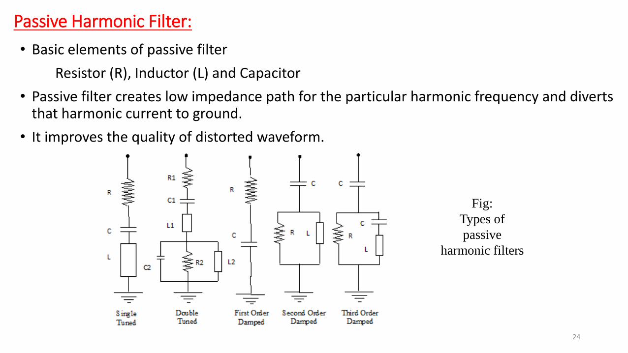
Passive Harmonic Filter: • Basic elements of passive filter
Resistor (R), Inductor (L) and Capacitor
• Passive filter creates low impedance path for the particular harmonic frequency and diverts that harmonic current to ground.
• It improves the quality of distorted waveform.
Fig:
Types of
passive
harmonic filters
24

Practical considerations of PHF: • Tuning: The filter is tuned slightly below the harmonic frequency generated by the load.
This will allow for tolerance in the filter components and variations in system impedance.
• Switching: Filters provide fundamental frequency reactive power (VAR). Portions of the filter can be switched off at times of minimum load to limit overvoltage.
• Tolerances: Capacitors and inductors must be designed such that the combination of ratings (L and C) does not result in resonance at an undesired frequency. In other words, there should not be positive peaks in the filter impedance curves to correspond with harmonic frequencies.

• Use active switching components (SCR,IGBT,MOSFET and etc.,)
• Only one filter needed to eliminate all the unwanted harmonics
• Used for power factor correction
Active Harmonic Filters:
Fig:
Active Filter
26
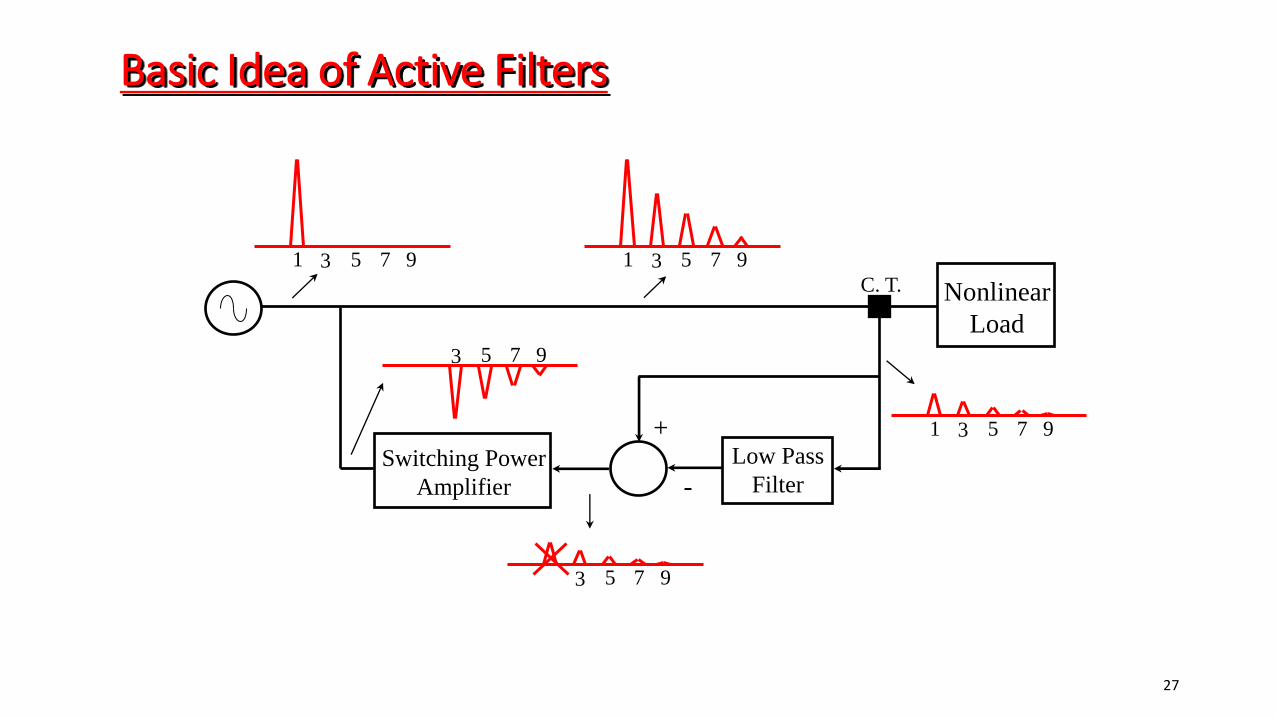
Nonlinear
Load
Low Pass
Filter
Basic Idea of Active Filters
C. T.
1 3 5 7 9
3 5 7 9
1 3 5 7 9
3 5 7 9
1 3 5 7 9
+
- Switching Power
Amplifier
27
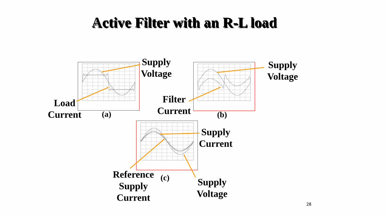
Active Filter with an R-L load
(c)
(a) (b)
Supply
Voltage
Supply
Current
Supply
Voltage
Reference
Supply
Current
Load
Current
Supply
Voltage
Filter
Current
28
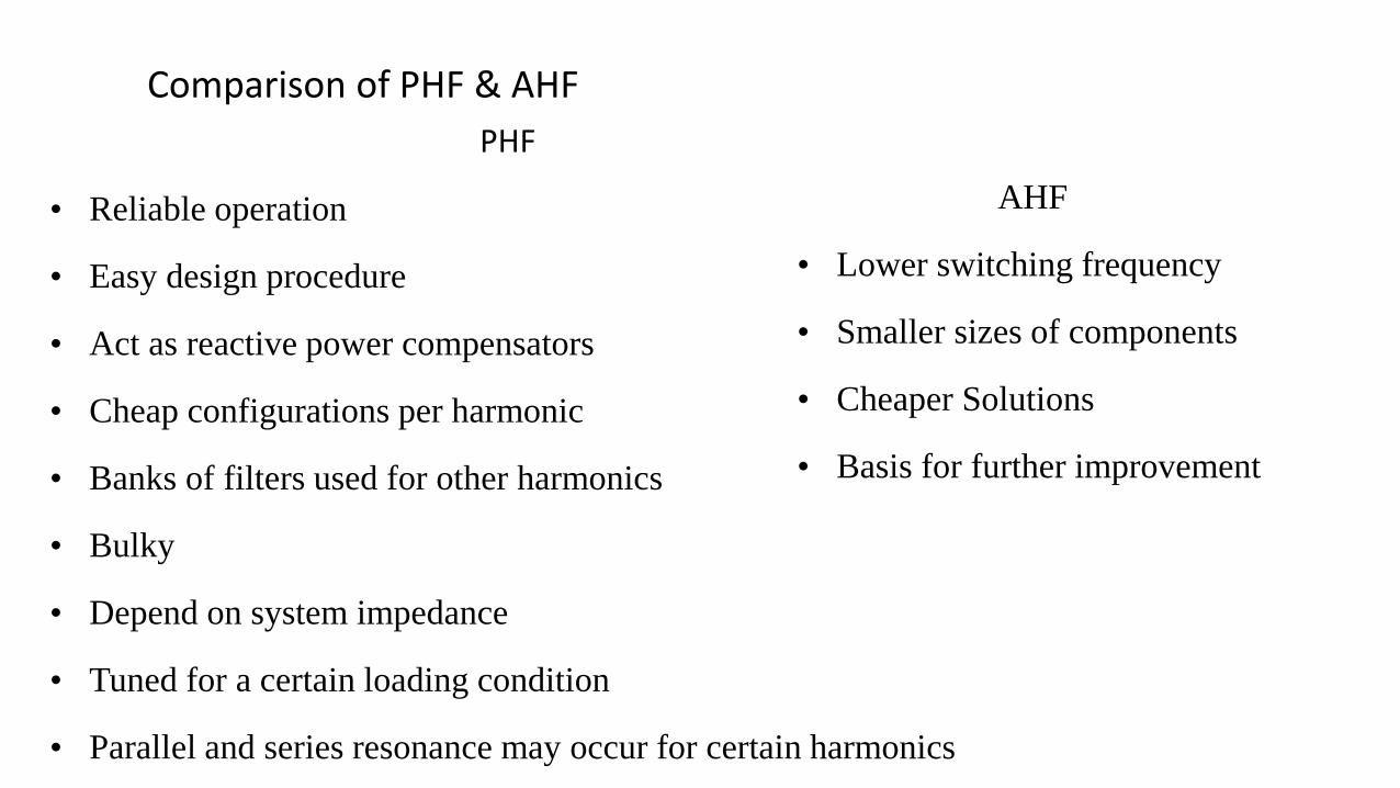
AHF
• Lower switching frequency
• Smaller sizes of components
• Cheaper Solutions
• Basis for further improvement
PHF
• Reliable operation
• Easy design procedure
• Act as reactive power compensators
• Cheap configurations per harmonic
• Banks of filters used for other harmonics
• Bulky
• Depend on system impedance
• Tuned for a certain loading condition
• Parallel and series resonance may occur for certain harmonics
Comparison of PHF & AHF
Hybrid Power Filter: • Hybrid power filter is nothing but the combination of both passive filter and active
filter.
• The hybrid filters are more attractive in harmonic filtering than the pure filters from both viability and economical points of view, particularly for high- power applications.
• Hybrid power filters consists of power electronic switching devices like MOSFET, IGBT, Thyristors, GTO and passive components such as capacitors, inductors and/or resistors.
30
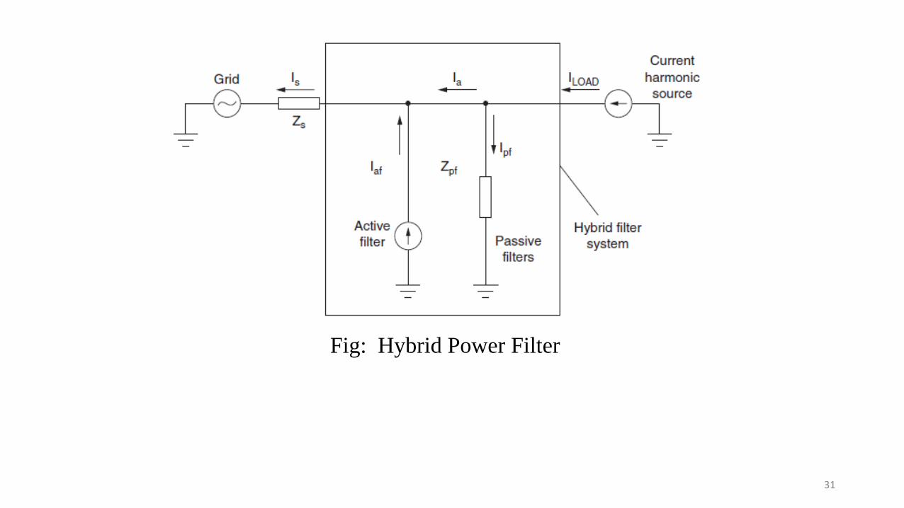
Fig: Hybrid Power Filter
31
32
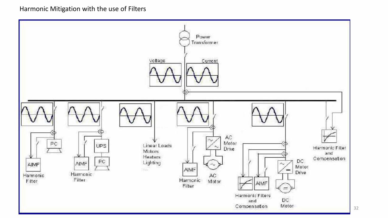
Harmonic Mitigation with the use of Filters

THANK YOU