power quality profile enhancement using hybrid fuzzy...
TRANSCRIPT
Power Quality Profile Enhancement using Hybrid Fuzzy-
Correlation Controller based UPQC
V.Veera Nagireddy1 Dr. Venkata Reddy Kota2 Dr. D.V. Ashok Kumar3
1Ibri College of Technology, Ibri, Oman.
2Dept of EEE, JNTU, Kakinada, A.P, India.
2Dept of EEE RGMCET, Nandyal, Kurnool (Dt.), A.P, India.
Abstract
The power quality is most significant parameter in distribution system to meet
quality requirements of modern end user sensitive equipment. This paper describes new
controller design for Unified Power Quality Conditioner (UPQC) in three phase distribution
network with non linear loads to enhance power quality. The voltage injection and current
injection schemes for UPQC has adapted the correlation based fuzzy logic control method
which is proposed to improve power quality profile. The reference unit vectors for
generating switching pulses are estimated for series and shunt converters by hybrid
correlation approach and fuzzy controller in order to mitigate harmonics, voltage sag,
voltage swell and load balancing. The mitigation of power quality issues is carried using
proposed method through MATLAB/Simulink. The performance of hybrid correlation fuzzy
controller based UPQC is observed to be satisfactory under non linear and time varying
load conditions.
Keywords: Unified Power Quality Conditioner; correlation approach; cross correlation
approach; fuzzy control; Voltage sag mitigation; total harmonic distortion; Voltage swell
mitigation; load balancing.
1 INTRODUCTION
In distribution systems from distribution substation to consumer end the power
quality plays significant impact on consumer equipment functioning and lifetime.
There may be large impact on better performance of sensitive electronics equipment
for small improvement in power quality below IEEE 519 standard (<5%) [1]. UPQC
combines the benefits of two custom power devices i.e., dynamic voltage restorer
(DVR) and distribution STATCOM (DSTATCOM). The present days research is
going on in the area of application of adaptive control schemes of custom power
devices for enhancing power quality in distribution systems particularly using soft
computing techniques [2]. The maintaining of power quality means providing
quality supply with voltage, current and frequency variations such that all end user
International Journal of Pure and Applied MathematicsVolume 114 No. 10 2017, 383-395ISSN: 1311-8080 (printed version); ISSN: 1314-3395 (on-line version)url: http://www.ijpam.euSpecial Issue ijpam.eu
383
equipments should operate without mal functioning through their extended period
of duration especially sensitive electronic equipment under abnormal conditions [3]-
[4]. The particle swarm optimization control method performance for three-phase
UPQC to mitigate the power quality issues under unbalanced load conditions and
various non-ideal mains voltage was analyzed [5]. The gating pulses are generated
for power converter using correlation approach for system identification of digital
control with FPGA. The multi period pseudo random binary signal based results are
proven to be better than conventional control scheme [6] and fast computational
speed with one computational operation can be achieved using cross correlation
approach [7]. ANN-digital signal process based controller is designed for shunt
active power filter and the system performance was better compared with
conventional PI controller [8]. Total harmonic distortion has been improved by I
cosα theory and synchronous reference theory (SRFT) and SRF theory has proved to
be better [9]. The analysis was carried out using noval Grey Wolf Optimization
(GWO) algorithm with improved dynamic performance and voltage sag mitigation
and compared with PI controller. [10] proposed comparative study on voltage source
converter based DSTATCOM using least mean square based adaptive linear
network and fuzzy logic.
1 SYSTEM CONFIGURATION AND PRINCIPLE
UPQC is a custom power device used to mitigate voltage sag, swell, eliminate
harmonics, compensate reactive power and correct current and voltage imbalances.
UPQC has series and shunt compensators, series compensation is used to eliminate
voltage disturbances like sag, swell and imbalances etc. by injecting series voltage,
whereas current disturbances are eliminated by shunt compensation by shunt
current injection. The schematic diagram of basic configuration for integration of
UPQC to three-phase distribution system is shown in figure 1. The shunt Voltage
Source Converter (VSC) is connected in shunt with the distribution system.
Whereas series VSC is connected in series to distribution lines at Point of Common
Coupling (PCC) through three- phase injection transformers. Figure 2 shows the
phasor diagram of the test network. From the phasor diagram the voltage and
current equations are given as
The DC voltage is common dc link for both series and shunt compensation circuits.
Fuzzy controller can regulate this dc voltage.
International Journal of Pure and Applied Mathematics Special Issue
384

Fig. 1 Basic configuration for integration of UPQC to three-phase distribution
system
Fig. 2 Phasor diagram of UPQC for (i) source voltage and Point of Common
Coupling (PCC) voltage are in phase. (ii) Source voltage and PCC voltage are not in
phase. (iii) In- phase voltage compensation scheme.
2 HYBRID FUZZY-CORRELATION CONTROL SCHEME
Series Controller Design: The schematic diagram of control scheme for series voltage
source converter of three phase UPQC is shown in figure 3. The reference inputs for
series control scheme are three phase source voltages (vsabc), three phase load
voltages (vlabc) and three phase load currents (ilabc). The three phase source voltages
are transformed to qd0 using Park’s transformation as:
International Journal of Pure and Applied Mathematics Special Issue
385

Similarly, for load voltages calculated using rotating reference frame.
These load voltages are as inputs for fuzzy controller and Vqr is the output of fuzzy
controller. The reference for series VSC is difference signal of these two signals as
expressed by equations (6) and (7) and (8).
The three phase (abc form) reference voltages for series VSC are:
The estimated reference voltages (9),(10) &(11) are compared with source voltages
and the subtracted signals are fed to pulse generator for generating gating pulses as
S1, S2, S3, S4, S5 and S6 for series VSC of UPQC.
Fig. 3 Control scheme for series VSC of UPQC
Shunt Controller Design: The amplitude of PCC voltage using sensed three phase source
voltages is given by
The in-phase three-phase unit voltages are estimated as
International Journal of Pure and Applied Mathematics Special Issue
386

The quadrature three-phase unit voltages are estimated as:
The instantaneous in phase source voltages (balanced) and non-linear load currents
are given by
Fig. 4 Control scheme for shunt VSC of UPQC
16)
The instantaneous in quadrature (with delay) source voltages (balanced) are
given by
The non- negative RMS values of source voltage ( ) and load current ( ) are:
Where ‘T’ is time period.
Correlation coefficient is given by
International Journal of Pure and Applied Mathematics Special Issue
387

Where =
Cross correlation coefficient is given by
=
The real component of phase ‘a’ load current is
Similarly, other (b & c) phases real power components ( ) can be obtained.
The reactive power components of load currents are estimated using equations (15),
(16), (17) & (21) as
Similarly, other (b & c) phases reactive power components ( ) can be
obtained.
The average amplitude of active and reactive power components of load currents are
The real power components of source currents are obtained by comparing dc
capacitor voltage with reference dc voltage. The error in dc voltage and dc link
voltage are given as inputs for fuzzy controller. The output of fuzzy controller is Ifsd
will be added to average amplitude of real power load current to obtain real power
component of reference current as
The reactive power components of source currents are obtained by comparing PCC
voltage ( ) with reference PCC voltage ( ). The error in PCC voltage and dc link
voltage are given as inputs for fuzzy controller. The output of fuzzy controller is Ifsq
will be added to average amplitude of reactive power load current to obtain reactive
power component of reference current as in equation (29). The shunt control scheme
is in figure 4.
International Journal of Pure and Applied Mathematics Special Issue
388
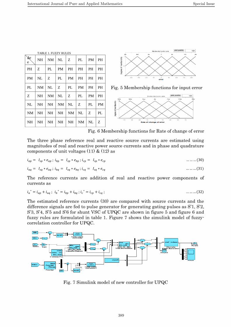
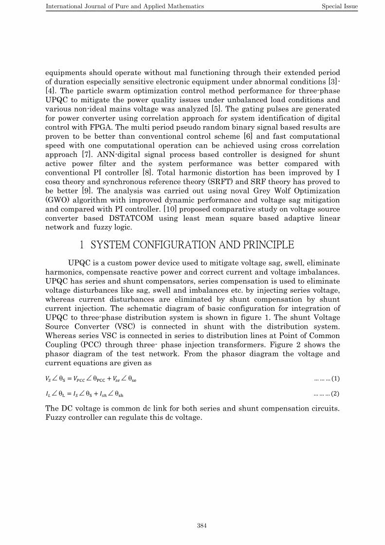
Fig. 5 Membership functions for input error
Fig. 6 Membership functions for Rate of change of error
The three phase reference real and reactive source currents are estimated using
magnitudes of real and reactive power source currents and in phase and quadrature
components of unit voltages (11) & (12) as
The reference currents are addition of real and reactive power components of
currents as
The estimated reference currents (30) are compared with source currents and the
difference signals are fed to pulse generator for generating gating pulses as S’1, S’2,
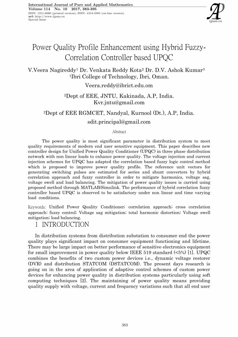
S’3, S’4, S’5 and S’6 for shunt VSC of UPQC are shown in figure 5 and figure 6 and
fuzzy rules are formulated in table 1. Figure 7 shows the simulink model of fuzzy-
correlation controller for UPQC.
Fig. 7 Simulink model of new controller for UPQC
TABLE 1. FUZZY RULES
e
e NH NM NL Z PL PM PH
PH Z PL PM PH PH PH PH
PM NL Z PL PM PH PH PH
PL NM NL Z PL PM PH PH
Z NH NM NL Z PL PM PH
NL NH NH NM NL Z PL PM
NM NH NH NH NM NL Z PL
NH NH NH NH NH NM NL Z
International Journal of Pure and Applied Mathematics Special Issue
389

3 RESULTS AND DISCUSSIONS
The performance of UPQC is carried using fuzzy-correlation approach on three
phase AC distribution system of 415V, 50 Hz, connected to three phase non-linear
load. The results are analyzed using MATLAB/SIMULINK with the source
resistance of 0.25 ohm and source inductanceof 1 mH. The common DC link voltage
is 250V.
Sag: The performance of UPQC for voltage sag condition is simulated and dynamic
performance using fuzzy-correlation approach is shown in figure 8. The source
voltage has voltage sag of 20% of nominal voltage for the duration of 0.1 sec (5
cycles) from 0.5 to 0.6 sec. It has been mitigated using fuzzy-correlation approach
based UPQC and the phase ‘a’ RMS values of source voltage and mitigated PCC
voltage versus duration are shown in figure.8.
Fig. 8 Dynamic performance of sag mitigation using fuzzy-correlation based
UPQC
Fig. 9 RMS value of Sag magnitude mitigation using fuzzy-correlation based UPQC
Swell: The fuzzy-correlation based control of UPQC for voltage swell condition is
simulated and its dynamic performance is shown in figure 10. The source voltage
has voltage swell of 120% of nominal voltage for the duration of 0.1 sec (5 cycles)
from 0.5 to 0.6 sec. It has been mitigated using fuzzy-correlation approach based
International Journal of Pure and Applied Mathematics Special Issue
390

UPQC and its RMS values of phase ‘a’ source voltage and voltage swell mitigated
PCC voltage versus duration are shown in figure 11.
Fig. 10 Dynamic performance swell mitigation using fuzzy-correlation based UPQC
Fig. 11 RMS value of Voltage swell mitigation using fuzzy-correlation based UPQC
Sag _ Swell:
Fig. 12 Dynamic performance of Voltage sag swell mitigation using fuzzy-
correlation based UPQC
International Journal of Pure and Applied Mathematics Special Issue
391

Fig. 13 RMS value of sag swell magnitude mitigation using fuzzy-correlation
based UPQC
The fuzzy-correlation based control of UPQC for voltage sag_swell condition is
simulated and its dynamic performance is shown in figure 11. The source voltage
has voltage sag of 20% from 0.2 to 0.3 sec and swell of 20% of nominal voltage from
0.4 to 0.5 sec. The sag and swell have been mitigated using fuzzy-correlation
approach based UPQC and its RMS values of phase ‘a’ source voltage with sag swell
and voltage sag swell mitigated PCC voltage versus duration are shown in figure
13.
Total Harmonic Distortion: The UPQC can also mitigate the harmonics that exists in the
three-phase distribution system due to non-linear loads. The shunt VSC
compensates the reactive power and the load harmonics. The load current has Total
Harmonic Distortion (THD) of 28.65% as shown in figure 16 and due to this
harmonic load current injection into the three-phase distribution system. The load
voltage harmonic distorted waveform and its compensated waveform using fuzzy-
correlation approach is shown in figure 14. From figures 15, 16 & 17, it is observed
that the non-linear load current has THD of 28.65% and source current has THD of
2.24% using fuzzy PI controller and it has been reduced to 1.37% using fuzzy-
correlation based controller. The PCC voltage has THD of 4.72% using fuzzy PI
controller and it has been reduced to 0.93% using fuzzy-correlation based controller
of UPQC and source voltage from 1.14% to 1.02% as shown in fig. 18.
Fig. 14 Harmonic distorted load voltage and its compensation using fuzzy-
correlation based UPQC
International Journal of Pure and Applied Mathematics Special Issue
392

Fig. 15 PCC voltage and total harmonic distortion using fuzzy-correlation based
UPQC
Fig. 16 Load current and total harmonic distortion
Fig. 17 Source current and total harmonic distortion with fuzzy-correlation based
UPQC
Fig. 18 Source voltage and total harmonic distortion with fuzzy-correlation based
UPQC
International Journal of Pure and Applied Mathematics Special Issue
393

4 CONCLUSION
UPQC can mitigate voltage sag, swell, sag swell, harmonics and balancing of
loads. The load current has total harmonic distortion of 28.65% and it has been
reduced by 80.29% at PCC and 10.52% reduction at source point and source current
harmonics are reduced by 38.83% using the Unified Power Quality Conditioner with
fuzzy-correlation control scheme as compared with fuzzy PI controller. The DC bus
voltage of UPQC is regulated by using fuzzy controller and terminal voltage can be
regulated with hybrid correlation – fuzzy control scheme. The proposed control
scheme is used for estimation of gating pulses for series and shunt voltage source
converters of UPQC. It is concluded that the proposed fuzzy–correlation control
scheme based UPQC reduces total harmonic distortions than fuzzy PI controller
within IEEE-519 standard limit (< 5%) [15].
References
[1] Fuchs Ewald F. and Mausoum Mohammad A. S., 2008.Power Quality in Power Systems and Electrical Machines, Elsevier Academic Press, London.
[2] S. N. Sivanandam and S. N. Deepa, Principle of Soft Computing. New Delhi, India: Wiley India Ltd., 2010.
[3] Alexander Kusko, Sc.D. and Marc T.Thompson, “Power Quality in Electrical Systems”, McGraw-Hill, 2007.
[4] Meral, M. Emin, et al. "Power quality improvement with an extended custom power park." Electric Power Systems Research 79.11 (2009): 1553-1560.
[5] Metin Kesler and Engin Ozdemir “A Novel Control Method for Unified Power Quality Conditioner
(UPQC) under Non-Ideal Mains Voltage and Unbalanced Load Conditions”, 25th Annual IEEE Applied Power Electronics Conference and Exposition (APEC), pp:374–379, 2010.
[6] B. Miao, R. Zane and D. Maksimovic, "System identification of power converters with digital
control through cross-correlation methods," in IEEE Transactions on Power Electronics, vol. 20, no. 5, pp. 1093-1099, Sept. 2005.
[7] Chaudhari, R. E., and S. B. Dhok. "Fast Quadtree Based Normalized Cross Correlation Method
for Fractal Video Compression using FFT." Journal of Electrical Engineering and Technology 11.2 (2016): 519-528.
[8] V. G. Kinhal, P. Agarwal and H. O. Gupta, "Performance Investigation of Neural-Network-Based
Unified Power-Quality Conditioner," in IEEE Transactions on Power Delivery, vol. 26, no. 1, pp. 431-437, Jan. 2011.
[9] Pal, Yash, A. Swarup, and Bhim Singh. "A novel control strategy of three-phase, four-wire UPQC for power quality improvement." Journal of Electrical Engineering and Technology 7.1 (2012):1-8.
[10] B. Singh, Sunil Kumar Dube, Sabha Raj Arya, A. Chandra and K. Al-Haddad, "A comparative
study of adaptive control algorithms in Distribution Static Compensator," Industrial Electronics Society, IECON 2013 - 39th Annual Conference of the IEEE, Vienna, 2013, pp. 145-150.
International Journal of Pure and Applied Mathematics Special Issue
394

395

396