power recovery in fl ifl oating lng regasificationplants · lng regasificationplants ... fsru •...
TRANSCRIPT

P R i Fl iPower Recovery in Floating LNG Regasification PlantsLNG Regasification Plants
Arindom GoswamiTechnical Professional Leader
M.W.Kellogg Ltd
Hans E. KimmelExecutive Director R&D
Ebara International CorporationggGreenford, UB6 0JA, U.K.
pSparks, NV 89434, [email protected]
KBR Paper 2218

Arindom Goswami is Senior Principal Engineer at MWArindom Goswami is Senior Principal Engineer at M.W.Kellogg Ltd , U.K. and received in 1995 a Bachelor Degree(Hons) in Mechanical Engineering. With his technical expertisein Rotating Equipment and his global management skills hein Rotating Equipment and his global management skills, hecontributed to the success of many upstream Oil & Gasprojects, including numerous LNG projects.
Hans E. Kimmel is Executive Director for Research andDevelopment at Ebara International Corporation. He holds aMaster Degree in Mechanical and Process Engineering and aPhD from Munich, Germany. His main contributions areprimarily in the LNG technology.

M. W. Kellogg LtdM. W. Kellogg LtdGreenford, UB6 0JA, U.K.
Ebara International Corp.pSparks, NV 89434, USA

FSRUthe Floating Storage Regasification Units,
FPSOthe Floating Production Storage and Offloading Unitsthe Floating Production, Storage and Offloading Units,
FDPSOthe Floating Drilling, Production, Storage and Offloading Units
are floating vessels used by the offshore industry forare floating vessels used by the offshore industry forthe drilling, processing, storage and transportation of
LNGLNGand for offloading the cargo in gaseous form
at the destinationat the destination.

Keppel Offshore & Marine Ltd © Keppel Offshore & Marine Ltd
FSRU “Golar Winter” Floating Storage and Regasification Unit for Golar LNG NorwayFloating Storage and Regasification Unit for Golar LNG, Norway

©
FPSO “Espirito Santo”
© Keppel Offshore & Marine Ltd
pFloating Production and Offloading Vessel for Petrobras, Brazil

© Keppel Offshore & Marine Ltd
W ld Fi t FDPSO “A it ”
© Keppel Offshore & Marine Ltd
World First FDPSO “Azurite” Floating Drilling, Production, Storage and Offloading Vessel

FSRUFSRU• The LNG is vaporized in a regasification unit on board the
l i t t l th h tvessel using ocean water or natural gas as the heat source.
• Due to the large temperature difference between the LNG andthe environment a substantial power recovery is suggestedthe environment, a substantial power recovery is suggested.
• This paper proposes and describes a modified Rankine Cycleto recover efficiently power from the floating regasification plantto recover efficiently power from the floating regasification plant.
• The power recovery is achieved using field proven rotatingand non-rotating equipment.g q p

• Even though the offshore regasification process is similarto the onshore process, the design of an offshore plantp , g pshows significant differences.
• Every square meter of an offshore footprint is relatively• Every square meter of an offshore footprint is relativelyexpensive since it requires the support of an offshorestructure. The design has to be compact to keep the surface
ll iblarea as small as possible.
• Due to the limited space, additional risk mitigationp gmeasures and HAZOP assessments are required.
• The continuous motion of the vessel impacts the design ofthe process equipment to be able to operate under thesethe process equipment to be able to operate under thesedynamic conditions.
• Rotating equipment has to be designed to withstand theadditional gyroscopic forces caused by the vesselmovements.movements.
• The required design of any equipment is such that thecenter of gravity is as low as possible to increase the stabilitycenter of gravity is as low as possible to increase the stabilityof the vessel.
The conventional regasification process for onshore and offshoreplants incorporates two major equipment:
The high-pressure send-out pump, to pump the LNG from storage through the vaporizer and up to
the high pipe line pressurethe high pipe line pressure
The vaporizer, to transform the LNG into gaseous natural gasto transform the LNG into gaseous natural gas
♦♦♦The proposed regasification process incorporates a thirdequipment, the power recovery system to partially regain theinput energy used in the overall processinput energy used in the overall process.

Cryogenic high pressureCryogenic high-pressureLNG pumps pressurize thefluid up to the high pipe linefluid up to the high pipe linepressure while it is still inthe liquid stateq

Pump General Design Criteria
Liquid LNGLiquid LNG
Model 6ECC-1212
Pump Design Pressure [bara] 133.4
Lowest Design Temperature [°C] -168
Operating Temperature [°C] -147
Rated Flow [m³/hr] 287[ ]
Rated Differential Head [m] 2396
Design Specific Gravity 417Design Specific Gravity .417
Maximum Specific Gravity .451
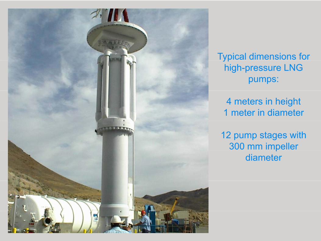
Typical dimensions for yphigh-pressure LNG
pumps:
4 meters in height1 meter in diameter
12 pump stages with 300 mm impeller p
diameter

Particular design features gfor high-pressure LNG pumps:
Single piece rotating shaft with integrally mounted
multi-stage pump hydraulics and electrical induction motor
Thrust balancing mechanism to eliminate high axial thrust forces
on the bearings
Electrical induction motor is b d i d l d b LNGsubmerged in and cooled by LNG
Ball bearings are lubricated and cooled by LNGand cooled by LNG

Power RecoveryLNG regasification plants are large heat sinks that require largeheat sources.
The differences in temperatures between the heat sources andthe heat sinks are in the range of 170° Celsius providing the pre-the heat sinks are in the range of 170 Celsius providing the preconditions for an efficient power recovery.
The Rankine Cycle is a thermodynamic cycle which convertsThe Rankine Cycle is a thermodynamic cycle which convertsheat into work. The heat is supplied externally to a closed loopwith a particular working fluid, and requires also a heat sink. Thiscycle generates about 80% of all global electric power.

P R iPower Recovery using a Rankine Power Cycle
The ideal Rankine Cycle consists of the following four processes:o e o o g ou p ocesses
1→2 Isentropic compression to high pressure in a pump2→3 Constant high pressure heat addition in a boiler2→3 Constant high pressure heat addition in a boiler3→4 Isentropic expansion in a turbine expander to low pressure4→1 Constant low pressure heat rejection in a condenser

Rankine Power Cycle with vapour expansion

Rankine Cycle with liquid-vapour two-phase expansion
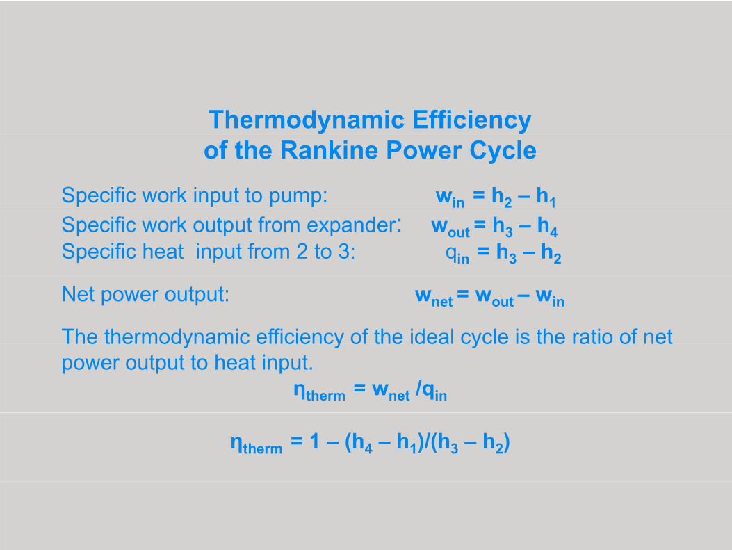
Thermodynamic Efficiency of the Rankine Power Cycle
Specific work input to pump: win = h2 – h1in 2 1Specific work output from expander: wout = h3 – h4Specific heat input from 2 to 3: qin = h3 – h2
Net power output: wnet = wout – win
The thermodynamic efficiency of the ideal cycle is the ratio of net e e ody a c e c e cy o e dea cyc e s e a o o epower output to heat input.
ηtherm = wnet /qin
ηtherm = 1 – (h4 – h1)/(h3 – h2)

T - expander turbineP pumpP - pumpG - generator
Schematic of Rankine Cycle with two-phase expansion
Schematic for Power Recovery Using Common Working Fluids with a Pump Two-Phase Expander Generator
For the Rankine cycle power recovery in LNG regasificationplants several field proven working fluids are available and usedin similar applicationsin similar applications.
To achieve a higher efficiency the working fluid is passed throughtwo heat exchangers and one set of a pump two phase expandertwo heat exchangers and one set of a pump two-phase expandergenerator, a compact assembly of a pump, a two-phaseexpander and an induction generator integrally mounted on onerotating shaft.
Schematic Description with Rankine Power Cycle
1→2With work input, the pump pressurizes the liquid single phase working fluidfrom low pressure to high pressurep g p
2→3The pressurized working fluid is heated by passing through the generatorand the heat exchanger with the heat provided by sea water or other heatg p ysources
3→4The pressurized and heated working fluid expands from high pressure to lowpressure across the two-phase expander generating a work output
4→1The low pressure working fluid passes through a heat exchanger with theh i k h LNG f ifi i Th ki fl id d fheat sink, the LNG for re-gasification. The working fluid condenses fromliquid-vapor two-phase to liquid single phase.
The compact assembly of a Pump Two-Phase Expander Generator p p
consists of a pump, p p
a two-phase expander, and an induction generator g
integrally mounted on one rotating shaft.

During start-up of the compact assembly theDuring start up of the compact assembly theinduction generator operates as inductionmotor below the synchronous speedmotor below the synchronous speed.
When the shaft power of the expander isWhen the shaft power of the expander isgreater than the shaft power of the pumpthen the induction motor operates in thethen the induction motor operates in thegenerator mode above the synchronousspeed.speed.
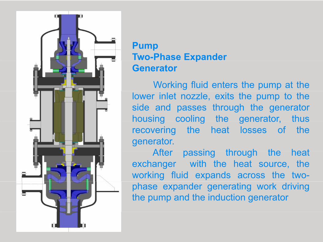
Pump Two-Phase Expander pGenerator
Working fluid enters the pump at thelower inlet nozzle, exits the pump to theside and passes through the generatorhousing cooling the generator, thushousing cooling the generator, thusrecovering the heat losses of thegenerator.
After passing through the heatAfter passing through the heatexchanger with the heat source, theworking fluid expands across the two-phase expander generating work drivingthe pump and the induction generator

Pump Two-Phase Expander p
GeneratorIn this modified design, the
pressurized fluid passes directly from thepump through the generator housingcooling the generator, then exits to thecooling the generator, then exits to theside and pass through the heatexchanger.
In both designs the leakage throughIn both designs, the leakage throughthe seal and the thrust is minimized due toequal pressure on both sides of the sealand opposing directions of the thrustforces.
Advantages of the compact assembly♦
The expander work output is larger than the pump work input andthe difference in work is converted by the generator into electricaly genergy
♦♦The losses of a separate pump motor are eliminatedThe losses of a separate pump motor are eliminated
♦♦♦The losses of the induction generator are recovered and used ash t t h t th ki fl id i dditi t th h t fheat source to heat the working fluid in addition to the heat fromsea water and other heat sources
♦♦♦♦Any leakage of the working fluid is within a closed loop andoccurs only between pump and expander
Advantages continuedAdvantages continued
♦♦♦♦♦Any leakage of the working fluid is minimized due to equalpressure on both sides of the seal, and small leakages are withina closed loop and occur only between pump expander anda closed loop and occur only between pump, expander andgenerator.
♦♦♦♦♦♦Th i l th t i i i i d d t i di ti f thThe axial thrust is minimized due to opposing directions of thethrust forces decreasing the bearing load and increasing thebearing life.
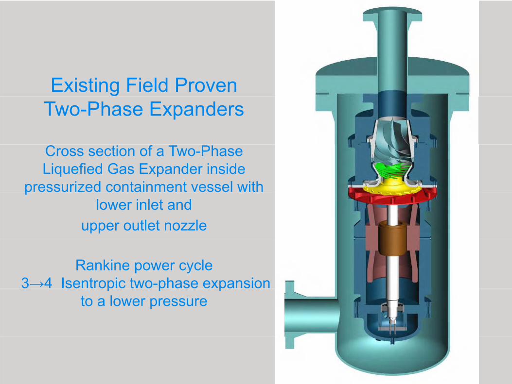
Existing Field Proven Two-Phase Expanders
Cross section of a Two-Phase Liquefied Gas Expander inside
pressurized containment vessel with plower inlet and
upper outlet nozzle
Rankine power cycle3→4 Isentropic two-phase expansion 3 se t op c t o p ase e pa s o
to a lower pressure

Two-Phasehydraulic assemblyhydraulic assembly
with nozzle ring (red)(red),
turbine runner (yellow), (y ),
jet exducer (green) and two-phase draft
tube (metallic)
3→4 Isentropic two phase expansion to a lower pressure3→4 Isentropic two-phase expansion to a lower pressure

Nozzle Ring with converging nozzles generates high-velocity vortex flow
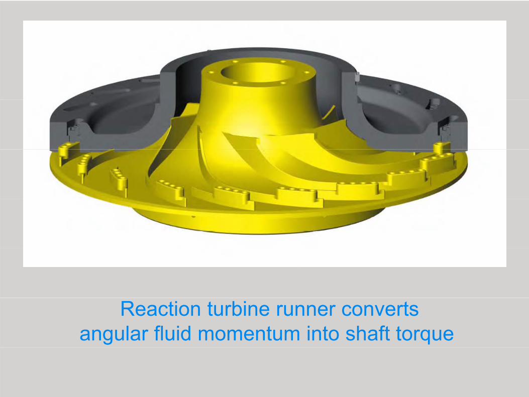
Reaction turbine runner converts angular fluid momentum into shaft torque

Jet ExducerJet Exducer
A radial outflow turbine for power generation by isentropictwo-phase expansion to lower pressuretwo-phase expansion to lower pressure
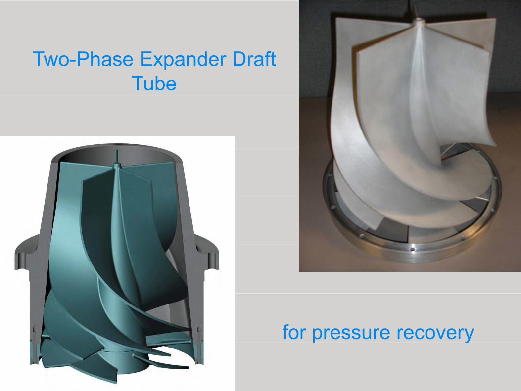
Two-Phase Expander Draft Tube
for pressure recoveryp y

Field Experience withField Experience with Liquefied Gas Two-Phase Expanders
Two-phase rich liquid feed expandersTwo phase rich liquid feed expanders installed in 2003 are operating
successfully at PGNiG, Odalanów, PolandPoland.
Additional two-phase expanders are installed in
the feed to the lower column during 2009.during 2009.

Two-Phase Liquefied Gas E d tExpander at
Stage Manufacturing

The presented pRankine Power Cycle,
incorporating a compact design p g p gconsisting of a pump, a two-phase liquefied gas expander and an induction generator, integrally p g , g ymounted on one single rotating shaft, offers an
efficient and economical power recovery
for floating LNG regasification plants g g p

Thank You for your attention
謝謝您的關注謝謝您的關注