power supply system aspiro 1u instruction manual · power supply system aspiro 1u instruction...
TRANSCRIPT

Power Supply SystemAspiro 1U
Instruction Manual
www.unipowerco.com
Document Number: M00035-MAN rev. 3a © 2017 UNIPOWER LLCAll Rights Reserved
UNIPOWER LLC • 3900 Coral Ridge Drive, Coral Springs, Florida 33065, USA • [email protected] America: +1 954-346-2442 • Latin America: +1 954-905-1078 • Europe: +44 1903 768200
P O W E R I N G T E C H N O L O G Y

Page 2
P O W E R I N G T E C H N O L O G Y
Document No. M00035-MAN rev. 3a aspiro1u_m35-man-rev3a-0417.indd
Copyright © 1999-2017 UNIPOWER LLC
All Rights Reserved
Restricted Rights Legend:
Use, duplication, or disclosure by the Government is subject to restrictions as set forth in subparagraph © (1)(ii) of the Rights in Technical Data and Computer Software clause at DFARS 252.227-7013 or subparagraphs © (1) and (2) of Commercial Computer Software - Restricted Rights at 48 CFR 52.227-19, as applicable.
For Contact Information, please go to http://www.unipowerco.com/contact/
Refer to the UNIPOWER License Agreement in this package before installing or using this product.
Unless specifically noted, all addresses, data characters and persons referenced herein, and all examples involving names of companies and products, are fictitious examples and are designed solely to illustrate the use of UNIPOWER products.
Product names, logos, brands, and other trademarks featured or referred to within this product manual are the property of their respective trademark holders. These trademark holders are not affiliated with UNIPOWER LLC or our products. They do not sponsor or endorse our products.
LIMITATIONS AND AUTHORIZATIONS FOR USE AND PERMITTED APPLICATIONS
UNIPOWER’s products are not designed, intended for use in, or authorized for use as critical components in, human life support systems/equipment, equipment used in hazardous environments, or equipment used in nuclear control equipment or systems. Any such use requires the prior express written consent of an authorized executive officer of UNIPOWER LLC, which consent may be withheld by UNIPOWER LLC in its sole discretion. Users assume all risk and liability for, and agree to indemnify and defend UNIPOWER from and against any claims for personal injury (including death) or property damage resulting from any such use or application which is made in the absence of such prior express written consent.
If you find errors or problems with this documentation, please notify UNIPOWER. UNIPOWER does not guarantee that this document is error-free. The information in this document is subject to change without notice.

Page 3
P O W E R I N G T E C H N O L O G Y
Document No. M00035-MAN rev. 3a aspiro1u_m35-man-rev3a-0417.indd
ContentsChapter 1 About This Manual1.1 Objectives ..................................................................................................................................61.2 Audience ....................................................................................................................................61.3 Document Key ...........................................................................................................................61.4 Feedback & Support ..................................................................................................................71.6 Disclaimer ..................................................................................................................................7
Chapter 2 Aspiro System Description2.1 Overview ....................................................................................................................................82.2 System Configurations ...............................................................................................................82.3 System Parameters .....................................................................................................................92.4 System Components.................................................................................................................11 2.4.1 System Controller ...........................................................................................................11 2.4.2 DC Distribution ...............................................................................................................11 2.4.4 Rectifier Module .............................................................................................................12
Chapter 3 System Safety3.1 Safety Warnings and Guidelines ..............................................................................................13 3.1.1 System Markings ............................................................................................................13 3.1.2 Safety Recommendations ................................................................................................13 3.1.3 Installation Warning ........................................................................................................14 3.1.4 Restricted Access Area Warnings....................................................................................14 3.1.5 Electrical and Fire Enclosure ..........................................................................................14 3.1.6 System Enclosure ............................................................................................................14 3.1.7 Operating Temperature Warnings ...................................................................................14 3.1.8 Electrical Safety Warnings ..............................................................................................14 3.1.9 Grounding .......................................................................................................................15 3.1.10 Batteries ........................................................................................................................16 3.1.10.1 Lead Acid Batteries ........................................................................................16 3.1.11 In Case of an Accident ..................................................................................................163.2 Caution .....................................................................................................................................17 3.2.1 Storage and Transportation .............................................................................................17 3.2.2 Disposal...........................................................................................................................17 3.2.3 Handling Electrostatic Sensitive Devices .......................................................................17 3.2.4 Traceability .....................................................................................................................17 3.2.5 Breakers ..........................................................................................................................17 3.2.5.1 Circuit Breaker Limitations .............................................................................17
Page 4
P O W E R I N G T E C H N O L O G Y
Document No. M00035-MAN rev. 3a aspiro1u_m35-man-rev3a-0417.indd
Chapter 4 Installation Guide4.1 Introduction ..............................................................................................................................194.2 Unpacking ................................................................................................................................194.3 Tools 194.4 Rack Mounting .........................................................................................................................194.5 Rear Connections .....................................................................................................................21 4.5.1 DC Earth Connection (FRAME GROUND) ..................................................................21 4.5.2 Mains Connection ...........................................................................................................22 4.5.3 Alarm and Signal Connections ........................................................................................23 4.5.4 DC Load Connections .....................................................................................................25 4.5.5 Battery Connections .......................................................................................................26 4.5.6 Symmetry Connection ....................................................................................................27 4.5.7 Temperature Sensor Connection .....................................................................................28
Chapter 5 Commissioning5.1 Commissioning Overview .......................................................................................................295.2 Tools and Test Equipment ........................................................................................................29 5.2.1 Tools List .........................................................................................................................29 5.2.2 Test Equipment ...............................................................................................................295.3 Preparation ...............................................................................................................................295.4 Commissioning procedure .......................................................................................................305.5 Test of output voltage ...............................................................................................................31 5.5.1 Float charge (U1) ............................................................................................................31 5.5.2 Adjustment of Float Charge, U1 .....................................................................................31 5.5.3 Boost charging (U2) (if applicable) ................................................................................315.6 Battery supervision ..................................................................................................................325.7 Battery test ...............................................................................................................................325.8 Commissioning record .............................................................................................................33
Chapter 6 Maintenance & Troubleshooting6.1 Maintenance .............................................................................................................................346.2 Troubleshooting .......................................................................................................................34
Chapter 7 Replacing Modules7.1 Controller Replacement ...........................................................................................................387.2 Rectifier Replacement ..............................................................................................................39 7.2.1 XR04.48 / XR08.48 Replacement ..................................................................................39 7.2.2 XPGe12.48 Replacement ................................................................................................397.3 Breaker Replacement ...............................................................................................................40
Appendix A - Block Diagram ......................................................................................................42Appendix B - CSA Certificate Extract .......................................................................................43Appendix C - Revision History ...................................................................................................44
Page 5
P O W E R I N G T E C H N O L O G Y
Document No. M00035-MAN rev. 3a aspiro1u_m35-man-rev3a-0417.indd
FIGURESFigure 2-1 Power System Overview ...........................................................................................8Figure 2-2 XPGe12.48 and XR04.48/XR08.48 ........................................................................12Figure 4-1 Dimensional Drawing (Front and Top View) ..........................................................20Figure 4-2 System Mounting (19” mount) ................................................................................20Figure 4-3 Rear Connections .....................................................................................................21Figure 4-4 DC Earth Connections .............................................................................................21Figure 4-5 Mains Connection (viewed from rear) .....................................................................22Figure 4-6 Mains Connection Detail .........................................................................................23Figure 4-7 Signal Pin Designations ...........................................................................................24Figure 4-8 Signal Connection Detail .........................................................................................25Figure 4-9 Load and Battery Connections (Rear View) ............................................................25Figure 4-10 Signal Connection Detail .........................................................................................26Figure 4-11 2-block Symmetry Measurement (for illustration only) ..........................................27Figure 4-12 4-Block Symmetry Measurement (for illustration only) .........................................27Figure 4-13 Temperature Sensor Connection ..............................................................................28Figure 7-1 Unlocking the Controller .........................................................................................38Figure 7-2 Removing the Controller .........................................................................................38Figure 7-3 Replacing an XR04.48 or XR08.48 Rectifier ..........................................................39Figure 7-3 Replacing an XPGe12.48 Rectifier ..........................................................................40Figure 7-5 Top Cover Removal .................................................................................................40Figure 7-6 Breaker Removal - A ...............................................................................................41Figure 7-7 Breaker Removal - B ...............................................................................................41
TABLESTable 4-1 Recommended Mains Circuit Protection .................................................................22Table 4-2 Cable Sizes ..............................................................................................................26Table 4-3 Cable Sizes ..............................................................................................................27Table 5-1 Float/Boost Charge Voltages ...................................................................................31Table 5-2 Commissioning Record ...........................................................................................33

Page 6
P O W E R I N G T E C H N O L O G Y
Document No. M00035-MAN rev. 3a aspiro1u_m35-man-rev3a-0417.indd
1. About This ManualThis chapter contains an overview of the information that is presented in this Power System Manual. This includes information on objectives, the intended audience, and the organization of this manual. In addition, this chapter also defines the conventions used to indicate warnings, cautions and noteworthy information.
1.1 Objectives
This manual describes the Power System, explains how to unpack and install the system, how to perform the initial power-up and operational system check.
The information presented in this document is current as of the publication date.
1.2 Audience
This manual is to be used by installers and technicians who are preparing the site for a new installation and installing the power system. This manual assumes that the technician has an understanding of power systems in general and understands safety procedures for working around AC and DC voltage.
The user of this document should be familiar with electronic circuitry and wiring practices and have some expertise as an electronic, power, or electromechanical technician.
1.3 Document Key
This manual uses the following conventions:
WARNING This symbol indicates a situation that could cause bodily injury. Always be aware of hazardous conditions when working in or around the power system.
CAUTION This symbol indicates a situation that might result in equipment damage. The reader should be aware that their actions could result in equipment or data loss.
NEED MORE INFORMATION? This symbol is used to reference information either in this manual or in another document.
NOTE This symbol means the reader should take note. Notes are helpful suggestions or reminders.
Chapter 1 About This Manual

Page 7
P O W E R I N G T E C H N O L O G Y
Document No. M00035-MAN rev. 3a aspiro1u_m35-man-rev3a-0417.indd
Table 1-1 AbbreviationsAbbreviation DescriptionPCC Prime Controller CardACC Advance Controller CardLVD Low Voltage DisconnectionPLD Partial Load DisconnectionXR04.48 400 W RectifierXR08.48 800 W RectifierXPGe12.48 1200 W RectifierDB22 Distribution Drawer (4 x load, 1 x battery)D22 Distribution Drawer (3 x load)D33 Distribution Drawer 2 x load)B33 Distribution Drawer (2 x battery)
1.4 Feedback & Support
For technical support or feedback, please visit http://www.unipowerco.com/contact/ for details.
Alternatively, email: [email protected]
1.5 Layout, Numbering and Printing
This manual is intended for two-sided black and white printing. Some pages are intentionally left blank.
1.6 Disclaimer
UNIPOWER is not responsible for system problems that are the result of installation or modification of the instructions provided in this manual.

Page 8
P O W E R I N G T E C H N O L O G Y
Document No. M00035-MAN rev. 3a aspiro1u_m35-man-rev3a-0417.indd
2.1 Overview
Aspiro DC power systems offer a range of solutions for diverse applications such as broadband access, cable head ends, micro/pico BTS Cells, Enterprise, E911, and GSM-R.
The Aspiro shelf system utilizes efficient, dense, and reliable plug-in rectifier modules XR04.48, XR08.48 or XPGe12.48, with output power available at either 400W, 800W or 1200W per rectifier, based upon a soft-switching approach. Features include wide input operating range, wide operating temperature, full self-protection and three LEDs for immediate rectifier status indication.
The power system can be managed locally through messages and alarm displayed on the LCD screen of the system controller or remotely, using the PC-based PowCom™ software, or through a web browser with Ethernet connection.
2.2 System Configurations
Aspiro 1U system consists of:
1. System Controller ACC Extended
2. 4 x Load and 1 x Battery breakers including LVD
3. XR04.48 / XR08.48 / XPGe12.48 Rectifiers (Maximum 2)
4. Rear Connections
12
3
4
Figure 2-1 Power System Overview
Chapter 2 Aspiro System Description
Page 9
P O W E R I N G T E C H N O L O G Y
Document No. M00035-MAN rev. 3a aspiro1u_m35-man-rev3a-0417.indd
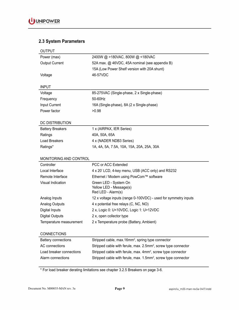
2.3 System Parameters
OUTPUTPower (max) 2400W @ >180VAC, 800W @ <180VACOutput Current 52A max. @ 46VDC, 45A nominal (see appendix B)
15A (Low Power Shelf version with 20A shunt)Voltage 46-57VDC
INPUTVoltage 85-275VAC (Single-phase, 2 x Single-phase)Frequency 50-60HzInput Current 16A (Single-phase), 8A (2 x Single-phase)Power factor >0.98
DC DISTRIBUTIONBattery Breakers 1 x (AIRPAX, IER Series)Ratings 40A, 50A, 65ALoad Breakers 4 x (NADER NDB3 Series)Ratings* 1A, 4A, 5A, 7.5A, 10A, 15A, 20A, 25A, 30A
MONITORING AND CONTROLController PCC or ACC ExtendedLocal Interface 4 x 20’ LCD, 4-key menu, USB (ACC only) and RS232Remote Interface Ethernet / Modem using PowCom™ software Visual Indication Green LED - System On
Yellow LED - Message(s) Red LED - Alarm(s)
Analog Inputs 12 x voltage inputs (range 0-100VDC) - used for symmetry inputsAnalog Outputs 4 x potential free relays (C, NC, NO)Digital Inputs 2 x, Logic 0: U<10VDC, Logic 1: U>12VDCDigital Outputs 2 x, open collector typeTemperature measurement 2 x Temperature probe (Battery, Ambient)
CONNECTIONSBattery connections Stripped cable, max.16mm2, spring type connectorAC connections Stripped cable with ferule, max. 2.5mm2, screw type connectorLoad breaker connections Stripped cable with ferule, max. 4mm2, screw type connectorAlarm connections Stripped cable with ferule, max. 1.5mm2, screw type connector
* For load breaker derating limitations see chapter 3.2.5 Breakers on page 3-6.
Page 10
P O W E R I N G T E C H N O L O G Y
Document No. M00035-MAN rev. 3a aspiro1u_m35-man-rev3a-0417.indd
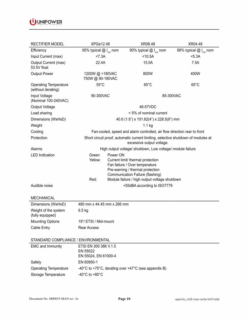
RECTIFIER MODEL XPGe12.48 XR08.48 XR04.48Efficiency 95% typical @ Iout nom 90% typical @ Iout nom 88% typical @ Iout nomInput Current (max) <7.3A <10.5A <5.3AOutput Current (max) 53.5V float
22.4A 15.0A 7.5A
Output Power 1200W @ >180VAC750W @ 90-180VAC
800W 400W
Operating Temperature (without derating)
55°C 65°C 65°C
Input Voltage(Nominal 100-240VAC)
90-300VAC 85-300VAC
Output Voltage 46-57VDCLoad sharing < 5% of nominal currentDimensions (WxHxD) 40.6 (1.6”) x 101.62(4”) x 228.5(9”) mmWeight 1.1 kgCooling Fan-cooled, speed and alarm controlled, air flow direction rear to frontProtection Short circuit proof, automatic current limiting, selective shutdown of modules at
excessive output voltage.Alarms High output voltage/ shutdown, Low voltage/ module failureLED Indication Green: Power ON
Yellow: Current limit/ thermal protection Fan failure / Over temperature Pre-warning / thermal protection Communication Failure (flashing)Red: Module failure / high output voltage shutdown
Audible noise <55dBA according to ISO7779
MECHANICALDimensions (WxHxD) 480 mm x 44.45 mm x 266 mmWeight of the system(fully equipped)
6.5 kg
Mounting Options 19”/ ETSI / Mid-mountCable Entry Rear Access
STANDARD COMPLIANCE / ENVIRONMENTALEMC and Immunity ETSI EN 300 386 V.1.5
EN 55022EN 55024, EN 61000-4
Safety EN 60950-1Operating Temperature -40°C to +75°C, derating over +47°C (see appendix B)Storage Temperature -40°C to +85°C
Page 11
P O W E R I N G T E C H N O L O G Y
Document No. M00035-MAN rev. 3a aspiro1u_m35-man-rev3a-0417.indd
2.4 System Components
The Aspiro system is delivered with all components mounted according to the ordered configuration. The main components are described below and in later chapters of the manual.
There are 2 versions of Aspiro shelf available depending on the value of battery current shunt used: 20 A or 80 A.
CAUTION Low Power Shelf version (20 A version) provides better resolution for battery current reading and it is suitable for low power applications with maximum battery charge current less than 5A.
2.4.1 System Controller
The Aspiro power system can be controlled by the ACC Extended or PCC controller. The description and operation of these controllers is covered in separate manuals which are available at:
ACC Extended: http://www.unipowerco.com/pdf/acc-man.pdf
PCC: http://www.unipowerco.com/pdf/pcc-man.pdf
2.4.2 DC Distribution
DC Distribution consists of maximum 1 battery and 4 load breakers available in a variety of sizes.
The distribution unit is designed for switching the battery and load on and off.
The battery and load breakers are supervised by measuring the voltage drop across each breaker. In the case of load breakers, those which are not connected to any load will not cause a breaker alarm even if they are left open.
A battery fuse alarm is generated after the battery voltage drops below a certain level, depending on the actual battery capacity and condition.
Low Voltage Disconnect (LVD)
The system is equipped with a low voltage battery disconnect which prevents the batteries from deep discharging, thus prolonging the battery life. The disconnect requires a detected mains failure at the supervision unit (controller).
If disconnection occurs, the batteries will not supply power to the load until they have been recharged to a set voltage level, which can be adjusted by the user.
If disconnection occurs, the batteries will be reconnected when the mains supply returns.

Page 12
P O W E R I N G T E C H N O L O G Y
Document No. M00035-MAN rev. 3a aspiro1u_m35-man-rev3a-0417.indd
2.4.4 Rectifier Module
The Fan-Cooled XPGe12.48 (1200W), XR08.48 (800W) and XR04.48 (400W) rectifiers are modular power supplies designed for parallel operation and hot-plug installation in the Aspiro Power Systems.
Each rectifier provides extremely reliable DC power in a very high density. The module incorporates power monitoring through an internal microprocessor, giving up to the second updates to the system controller and companion rectifiers. This guarantees tightly controlled load sharing among rectifiers, and provides status and identification information to the controller.
The rectifiers operate in parallel using active load sharing. They incorporate soft-start at both the input and the output, which protects against high incoming and outgoing currents. The output voltage of the rectifier is automatically adjusted to the required voltage by the controller.
Figure 2-2 XPGe12.48 and XR04.48/XR08.48
XPGe12.48 rectifiers cannot be used in the same rack as XR04.48 / XR08.48 rectifiers.
CAUTION XPGe12.48 rectifiers cannot be used in the same system as XR04.48/XR08.48 rectifiers.

Page 13
P O W E R I N G T E C H N O L O G Y
Document No. M00035-MAN rev. 3a aspiro1u_m35-man-rev3a-0417.indd
Chapter 3 System Safety
3.1 Safety Warnings and Guidelines
The following warnings and guidelines should be followed by properly trained and authorized personnel when installing, operating, commissioning or maintaining this equipment. Neglecting the instructions may be dangerous to personnel and equipment.
3.1.1 System Markings
The following markings are found on the Power System:
Ground Symbol
DC Ground Symbol
Product Label - The product label contains the system part number, model number, system ratings and safety approvals. The label is located on the left side of top cover.
3.1.2 Safety Recommendations
Any device that uses electricity requires proper guidelines to ensure safety.
• The Power System should only be installed or serviced by a qualified personnel.
• Always keep tools away from walkways and aisles. Tools present a tripping hazard in confined areas.
• Keep the system area clear and dust-free during and after the installation.
• Always know the location of emergency shut-off switches in case of an accident.
• Always wear appropriate eye protection and use appropriate tools for working with high voltage equipment.
• Do not perform any action that creates a potential hazard to other people in the system area.
• Never work alone in potentially hazardous conditions.
• Always check for possible hazards before beginning work.
• Remove watches, rings and jewelry that may present a hazard while working on the power system.

Page 14
P O W E R I N G T E C H N O L O G Y
Document No. M00035-MAN rev. 3a aspiro1u_m35-man-rev3a-0417.indd
3.1.3 Installation Warning
The following safety guidelines should be observed when transporting or moving the system:
• Before moving the Power System, read the system specifications sheet to determine whether the install site meets all the size, environmental, and power requirements.
• The system and the equipment included, should only be moved and installed by qualified personnel to prevent bodily injury or any other hazardous conditions.
3.1.4 Restricted Access Area Warnings
The Power System is designed for installation in locations with restricted access often secured by a locking mechanism. It can therefore be accessed only by a trained service person, who is fully aware of the restrictions applied to the location, or by an authority responsible for the location.
3.1.5 Electrical and Fire Enclosure
The unit is for building-in. A suitable Electrical and Fire enclosure shall be provided.
3.1.6 System Enclosure
Appropriate measures need to be taken to avoid intrusion of any unwanted objects or insects into conductive areas of the power system as there is a potential risk of system damage.
Disclaimer: UNIPOWER LLC assumes no liability or responsibility for system failures resulting from inappropriate enclosure around the system.
3.1.7 Operating Temperature Warnings
To prevent the Power System from overheating, an automatic shutdown mechanism has been installed. It is not recommended to continually operate the Power System in an area that exceeds the maximum recommended operating temperature.
3.1.8 Electrical Safety Warnings
The following are electrical safety recommendations for working near the Power System:
WARNING Observe low voltage safety precautions before attempting to work on the system when power is connected. Potentially lethal voltages are present within the system.
Page 15
P O W E R I N G T E C H N O L O G Y
Document No. M00035-MAN rev. 3a aspiro1u_m35-man-rev3a-0417.indd
WARNING Caution must be exercised when handling system power cables. Damage to the insulation or contact points of cables can cause contact with lethal voltages. For safety reasons, cables should be connected to the power system before power is applied.
• Remove all metallic jewelry like watches or rings that may present a hazard while working on the power system.
• Before connecting the AC input source to the power system, always verify voltage.
• Verify the AC source capacity. See system specifications for AC information.
• All AC connections must conform to local codes and regulations, e.g. ANSI, CEC, NEC, etc.
• When making AC connections, all AC power and DC load distribution breakers should be in the OFF position.
• All circuit breakers should meet the original design specifications of the system. In addition, equipment connected to the system should not overload the circuit breakers as this may have a negative effect on overcurrent protection and supply wiring, causing system or user harm.
• Verify the DC capacity before making connections. See system specifications for DC information.
• Potentially lethal voltages are present within the system. Ensure that all power supplies are completely isolated by turning all power switches OFF, disconnecting all relevant connectors and removing all relevant breakers before attempting any maintenance work. Do not rely on switches alone to isolate the power supply. Batteries should also be disconnected.
• Potentially lethal voltages are present within this system. Ensure that low voltage safety requirements are implemented before attempting to work on the system with power connected.
• Potentially lethal voltages can be induced if the equipment is not grounded (earthed) correctly. Ensure that all ground connections are secure.
3.1.9 Grounding
WARNING Grounding connection must be performed before operating the system. Refer to local codes, e.g. ANSI, CEC, NEC, T1-333, ETSI 300-386-TC specifying the connection of power system to building ground. In case of any doubt regarding the grounding connection, please contact a person responsible for the system.
Page 16
P O W E R I N G T E C H N O L O G Y
Document No. M00035-MAN rev. 3a aspiro1u_m35-man-rev3a-0417.indd
WARNING The system should be hard-wired to the incoming earth ground. A solid high current ground connection capable of sinking the maximum system current is required.
3.1.10 Batteries
WARNING When installing or replacing batteries, there is risk of explosion if an incorrect battery type is used.
3.1.10.1 Lead Acid Batteries
WARNING This equipment may use Lead Acid Batteries. When handling batteries, follow the instructions included with the battery set, as the fluids contained within these batteries are known to be a health hazard. The disposal of lead acid batteries is subject to legal requirements for hazardous waste disposal. Local guidelines should be followed for disposal.
Ensure the following guidelines are observed when dealing with equipment that may contain lead acid batteries:
• Any attempt to burn these batteries may result in an explosion and the generation of toxic fumes.
• Should a lead acid battery suffer damage, it must be moved into a well-ventilated area. Contact with the corrosive fluid must be avoided.
• Neutralize any acid corrosion with copious amounts of a solution of baking soda and water, and then wipe off all traces of soda.
• If the lead acid battery is removed from the equipment, any exposed contact must be insulated prior to disposal.
• Ensure that protective full-face shields, rubber gloves and aprons are worn and insulated tools are used when working with the batteries. It is advised also to have water available in case acid gets in contact with the eyes.
3.1.11 In Case of an Accident
In the event of an accident resulting in injury:
1. Use caution and check for hazards in the area.
2. Disconnect power to the system.
3. If possible, send someone to get medical aid. If not, check the condition of the victim and call for help.

Page 17
P O W E R I N G T E C H N O L O G Y
Document No. M00035-MAN rev. 3a aspiro1u_m35-man-rev3a-0417.indd
3.2 Caution
3.2.1 Storage and Transportation
CAUTION During storage and transportation, the units must remain in their original packages in order to avoid mechanical damage, maintain tracability, and protect the units against electrostatic discharge.
3.2.2 Disposal
CAUTION The product should not be disposed with other wastes at the end of its working life so as to prevent possible harm to the environment or human health from uncontrolled waste disposal.
3.2.3 Handling Electrostatic Sensitive Devices
CAUTION An electrostatic sensitive device is an electronic component that may be permanently damaged by the discharge of electrostatic charges encountered in routine handling, testing and transportation.
3.2.4 Traceability
CAUTION Units are labeled with permanently attached product identification labels. The labels are designed to be indelible throughout the life span of the equipment, unless mistreated. Make sure that the product identification labels are present on the equipment and are not subjected to unusual wear or mistreatment.
3.2.5 Breakers
CAUTION Breakers should always be replaced with the same type and rating in order to avoid damage to system components.
3.2.5.1 Circuit Breaker Limitations
1. Limitations for ambient temperature up to 47°C, maximum system output current 45 Amps:Maximum load per circuit breakers rated:1A, 4A, 5A, 7.5A, 10A, 15A, 20A and 25A is 80% of their nominal rate.Maximum load per circuit breaker rated 30A is 60% of its nominal rate.
Page 18
P O W E R I N G T E C H N O L O G Y
Document No. M00035-MAN rev. 3a aspiro1u_m35-man-rev3a-0417.indd
2. Limitations for ambient temperature up to 55°C, maximum system output current 45 Amps:Maximum load per circuit breakers rated:1 A, 4 A, 5 A, 7.5 A, 10 A, 15 A, 20 A and 25 A is 80% of their nominal rate.Maximum load per circuit breaker rated 30 A is 60% of its nominal rate.
3. Limitations for ambient temperature up to 75°C, maximum system output current 28 Amps: Maximum load per circuit breakers rated:1 A, 4 A, 5 A, 7.5 A, 10 A, 15 A, 20 A and 25 A is 30% of their nominal rate.Maximum load per circuit breaker rated 30 A is 20% of its nominal rate.
Page 19
P O W E R I N G T E C H N O L O G Y
Document No. M00035-MAN rev. 3a aspiro1u_m35-man-rev3a-0417.indd
Chapter 4 Installation Guide
WARNING There are potential hazards related to installing this power system. It is important to carefully read and understand the contents of Chapter 3 System Safety before performing system installation.
CAUTION Make sure sufficient room is left around the system, enabling optimal air circulation and thus preventing the system from overheating. Keep vent openings from blocking.
4.1 Introduction
This chapter provides detailed instructions for installing the Aspiro 1U Power System.
4.2 Unpacking
Check that the received equipment is in accordance with the packing list. Ensure that the cabinet and the equipment have not been damaged during transportation.
Report any parts that are damaged, missing or incorrect. If possible, correct the problem before continuing.
4.3 Tools
The following tools are required for a safe installation of the system:
WARNING Use only single-ended, fully insulated tools. Shafts of for example screwdrivers should be insulated.
• Anti-static hand strap.
• Insulated screwdrivers, flat, sizes 1, 2 and 3.
• Insulated screwdrivers, pozidrive (cross-slot), sizes 1, 2 and 3.
• Insulated torque spanner (for battery connection).
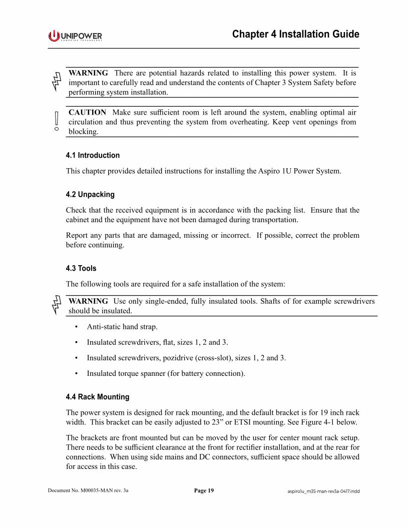
4.4 Rack Mounting
The power system is designed for rack mounting, and the default bracket is for 19 inch rack width. This bracket can be easily adjusted to 23” or ETSI mounting. See Figure 4-1 below.
The brackets are front mounted but can be moved by the user for center mount rack setup. There needs to be sufficient clearance at the front for rectifier installation, and at the rear for connections. When using side mains and DC connectors, sufficient space should be allowed for access in this case.
Page 20
P O W E R I N G T E C H N O L O G Y
Document No. M00035-MAN rev. 3a aspiro1u_m35-man-rev3a-0417.indd
0.22 (5.6)
0.98 (25.0)
1.26 (32.0)
0.98 (25.0)
10.49
(266
.45)
16.81 (426.9)
22.21 (564.2) [23”]22.90 (581.7) [23”]
18.90 (480.1) [19”]
18.21 (462.6) [19”]1.25 (31.75)
1.72(43.6)
0.27 (6.8 )
7.19 (18
2.5)
0.55 (14.05)
0.98 (25.0)
0.59 (15.0)
0.98 (25.0)
7.52 (190
.95)
10.30
(261.0
)
10.6
3 (270.0
)
19” 23”
Figure 4-1 Dimensional Drawing (Front and Top View)
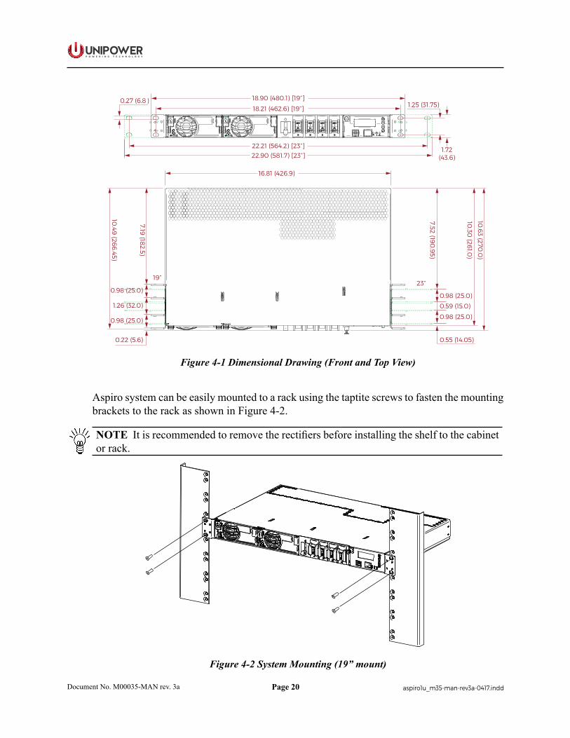
Aspiro system can be easily mounted to a rack using the taptite screws to fasten the mounting brackets to the rack as shown in Figure 4-2.
NOTE It is recommended to remove the rectifiers before installing the shelf to the cabinet or rack.
Figure 4-2 System Mounting (19” mount)
Page 21
P O W E R I N G T E C H N O L O G Y
Document No. M00035-MAN rev. 3a aspiro1u_m35-man-rev3a-0417.indd
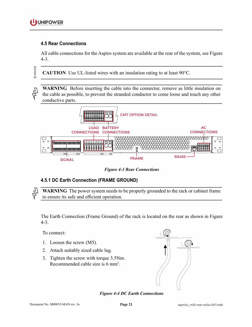
4.5 Rear Connections
All cable connections for the Aspiro system are available at the rear of the system, see Figure 4-3.
CAUTION Use UL-listed wires with an insulation rating to at least 90°C.
WARNING Before inserting the cable into the connector, remove as little insulation on the cable as possible, to prevent the stranded conductor to come loose and touch any other conductive parts.
SIGNALCONNECTIONS
BATTERYCONNECTIONS
ACCONNECTIONS
RS485
LOADCONNECTIONS
FRAMEGROUND 1-phase 2 x 1-phase
X9 X10 X6 X5
GMT OPTION DETAIL
Figure 4-3 Rear Connections
4.5.1 DC Earth Connection (FRAME GROUND)
WARNING The power system needs to be properly grounded to the rack or cabinet frame to ensure its safe and efficient operation.
The Earth Connection (Frame Ground) of the rack is located on the rear as shown in Figure 4-3.
To connect:
1. Loosen the screw (M5).2. Attach suitably sized cable lug.3. Tighten the screw with torque 3.5Nm.
Recommended cable size is 6 mm2.
Figure 4-4 DC Earth Connections

Page 22
P O W E R I N G T E C H N O L O G Y
Document No. M00035-MAN rev. 3a aspiro1u_m35-man-rev3a-0417.indd
4.5.2 Mains Connection
WARNING Ensure that mains input is turned off before connecting. The grounding must be connected to PE terminal as first.
CAUTION Depending on deployment region with regards to lightning strikes and heavy inductive energy, it is highly recommended to install AC Surge Protection Class C.
The Aspiro system family is available with two options for mains connection:
• Single-phase / Phase to Phase (USA) connection
• 2x Single-phase / Phase to Phase (USA) connection
First, check which mains solution is delivered and then follow the appropriate installation instructions below.
Connectors are situated on the right rear side of the system (Figure 4-3), labeled and configured as seen in Figure 4-5.
SIGNALCONNECTIONS
BATTERYCONNECTIONS
ACCONNECTIONS
RS485
LOADCONNECTIONS
FRAMEGROUND 1-phase 2 x 1-phase
X9 X10 X6 X5
GMT OPTION DETAIL
Figure 4-5 Mains Connection (viewed from rear)
Shelf Type(See product label)
Number of Rectifiers
Imax at100 VAC
RecommendedMains CB
XR04.48 XR08.48 XPGe12.48Single-phase
AC Input2
18.6 Aat 100VAC
C25A C32A C32A
2 x Single-phaseAC Input
29.3 A
at 100VAC2 x C25A 2 x C32A 2 x C32A
Table 4-1 Recommended Mains Circuit Protection

Page 23
P O W E R I N G T E C H N O L O G Y
Document No. M00035-MAN rev. 3a aspiro1u_m35-man-rev3a-0417.indd
To connect:
1. Remove sufficient insulation from the cables and insert stripped cables into the appropriate terminal.
2. Tighten the corresponding terminal screw with a flat screwdriver, see Figure 4-6.Maximum cable size is 2.5mm2. Maximum torque required for tightening the screw is 0.5Nm.
Figure 4-6 Mains Connection Detail
4.5.3 Alarm and Signal Connections
Alarm and Signal connections are positioned on the left rear side of the Power Shelf, see Figure 4-3.
For remote supervision of alarms, there are 4 potential free alarm contacts available. Each alarm contact represents different condition. Multi Purpose Voltage Inputs 1-12 can be reconfigured as external analog inputs.
The pin description detail for all signal connections is shown in Figure 4-7.
Alarm connections are Form C relays and can be monitored either Normally Closed (NC) or Normally Opened (NO). When the power is OFF NC is closed and when the power is ON NC is open.
NOTE Each alarm contact represents a different alarm condition or conditions. These is defined in the controller’s alarm matrix setup.

Page 24
P O W E R I N G T E C H N O L O G Y
Document No. M00035-MAN rev. 3a aspiro1u_m35-man-rev3a-0417.indd
7 78 89 94 45 56 6
1 12 23 3
X9 X10
Multip
urpo
se 10
Multip
urpo
se 11
Multip
urpo
se 12
10 11 12 13 14 15 16 17 18 10 11 12 13 14 15 16 17 18
0V Sens
e+5
V
0V Sens
e+5
V
BatteryTemp.
AmbientTemp.
Alar
m 4 -
CAl
arm
4 - N
CAl
arm
4 - N
O
Alar
m 1 -
CAl
arm
1 - N
CAl
arm
1 - N
O
Alar
m 2 -
CAl
arm
2 - N
CAl
arm
2 - N
O
Alar
m 3 -
CAl
arm
3 - N
CAl
arm
3 - N
O
Multip
urpo
se 1
Multip
urpo
se 2
Multip
urpo
se 3
Multip
urpo
se 4
Multip
urpo
se 5
Multip
urpo
se 6
Multip
urpo
se 7
Multip
urpo
se 8
Multip
urpo
se 9
Digit
al In
1Di
gital
In 2
Digit
al Ou
t 1
Digit
al Ou
t 2- V
Sys
.+V
Sys
.
Alarm Condition ShownCNCNO
Figure 4-7 Signal Pin Designations
Page 25
P O W E R I N G T E C H N O L O G Y
Document No. M00035-MAN rev. 3a aspiro1u_m35-man-rev3a-0417.indd
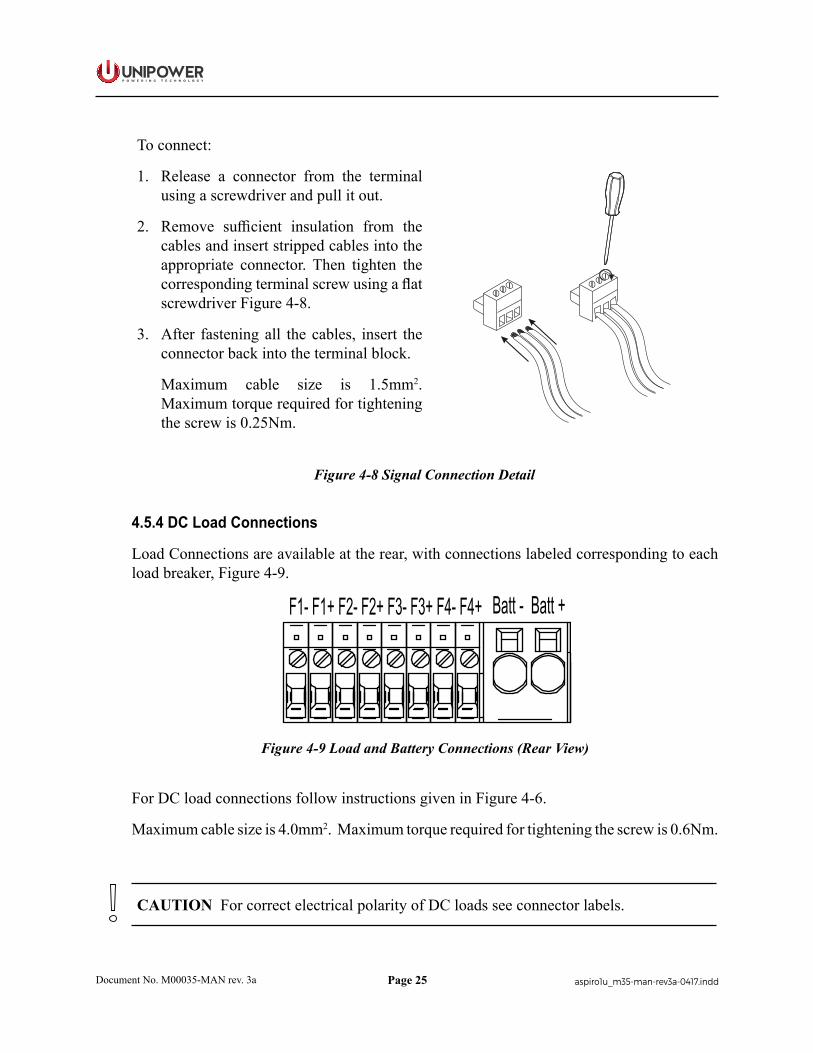
To connect:
1. Release a connector from the terminal using a screwdriver and pull it out.
2. Remove sufficient insulation from the cables and insert stripped cables into the appropriate connector. Then tighten the corresponding terminal screw using a flat screwdriver Figure 4-8.
3. After fastening all the cables, insert the connector back into the terminal block.
Maximum cable size is 1.5mm2. Maximum torque required for tightening the screw is 0.25Nm.
Figure 4-8 Signal Connection Detail
4.5.4 DC Load Connections
Load Connections are available at the rear, with connections labeled corresponding to each load breaker, Figure 4-9.
F1- F1+ F2- F2+ F3- F3+ F4- F4+ Batt - Batt +
Figure 4-9 Load and Battery Connections (Rear View)
For DC load connections follow instructions given in Figure 4-6.
Maximum cable size is 4.0mm2. Maximum torque required for tightening the screw is 0.6Nm.
CAUTION For correct electrical polarity of DC loads see connector labels.
Page 26
P O W E R I N G T E C H N O L O G Y
Document No. M00035-MAN rev. 3a aspiro1u_m35-man-rev3a-0417.indd
Load Breaker Size
[A]1A 4A 5A 7.5A 10A 15A 20A 25A 30A
Wire Size [mm2/AWG] 1/18 1/18 1/18 1/18 1/18 2.5/14 2.5/14 4/12 4/12
Table 4-2 Cable Sizes
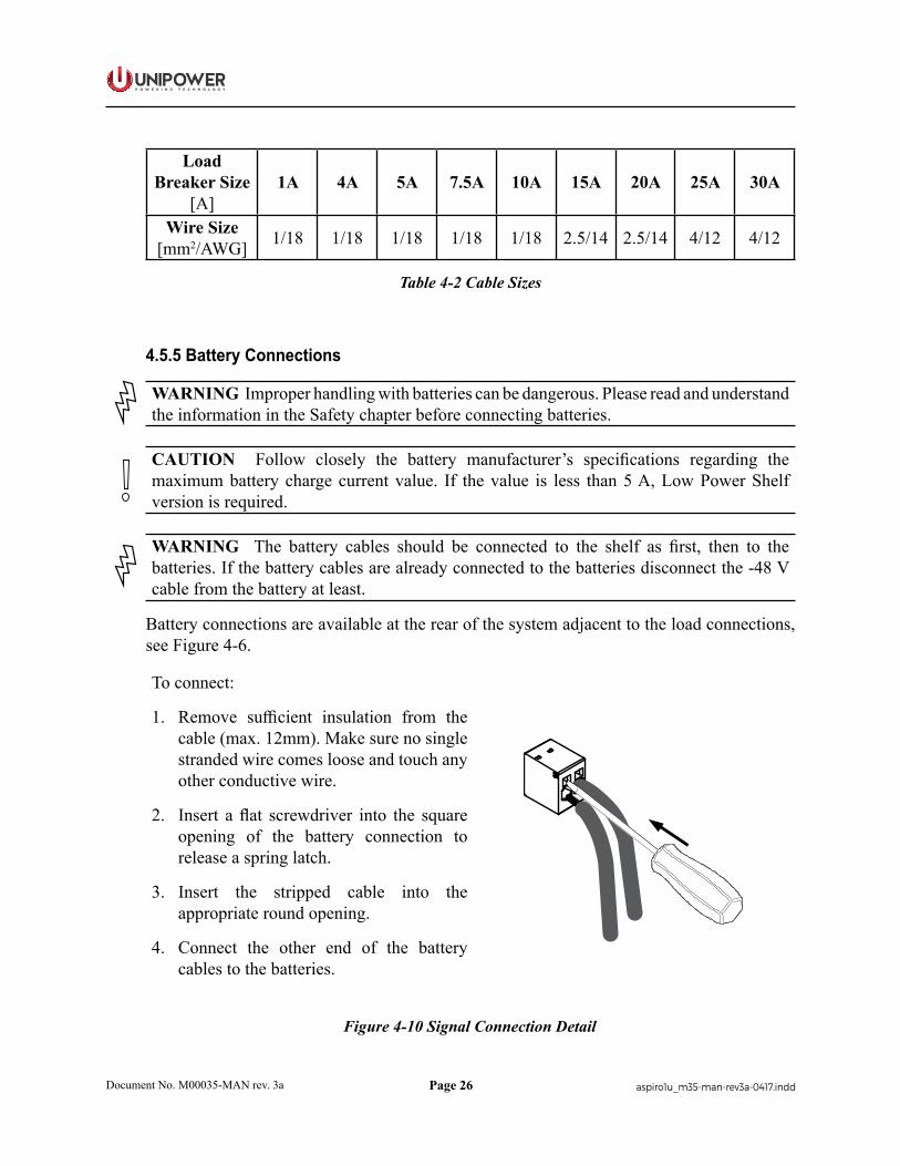
4.5.5 Battery Connections
WARNING Improper handling with batteries can be dangerous. Please read and understand the information in the Safety chapter before connecting batteries.
CAUTION Follow closely the battery manufacturer’s specifications regarding the maximum battery charge current value. If the value is less than 5 A, Low Power Shelf version is required.
WARNING The battery cables should be connected to the shelf as first, then to the batteries. If the battery cables are already connected to the batteries disconnect the -48 V cable from the battery at least.
Battery connections are available at the rear of the system adjacent to the load connections, see Figure 4-6.
To connect:
1. Remove sufficient insulation from the cable (max. 12mm). Make sure no single stranded wire comes loose and touch any other conductive wire.
2. Insert a flat screwdriver into the square opening of the battery connection to release a spring latch.
3. Insert the stripped cable into the appropriate round opening.
4. Connect the other end of the battery cables to the batteries.
Figure 4-10 Signal Connection Detail

Page 27
P O W E R I N G T E C H N O L O G Y
Document No. M00035-MAN rev. 3a aspiro1u_m35-man-rev3a-0417.indd
Battery Breaker Size
[A]40A 50A 65A
Wire Size [mm2/AWG] 10/6 10/6 16/4
Table 4-3 Cable Sizes
4.5.6 Symmetry Connection
1. Attach the interblock connection plates between the batteries.
2. Insert a suitably sized cable lug into one pole of the interblock connection plate. Fasten the lugs and plates to individual battery poles.
3. For 2-block battery symmetry measurement fix one wire of the symmetry cable to the cable lug in the mid-point of the battery string, see Figure 4-11.
4. For 4-block measurement fix the 3 wires (red, green and blue) of the symmetry cable to individual cable lugs. Colour coding of the cables must be respected for proper symmetry measurement see Figure 4-12.
Figure 4-11 2-block Symmetry Measurement (for illustration only)
Figure 4-12 4-Block Symmetry Measurement (for illustration only)
Page 28
P O W E R I N G T E C H N O L O G Y
Document No. M00035-MAN rev. 3a aspiro1u_m35-man-rev3a-0417.indd
NOTE The interblock Connection Kit is not delivered with the system.
NOTE Symmetry cable is normally pre-connected to the system, see Figure 4-7.
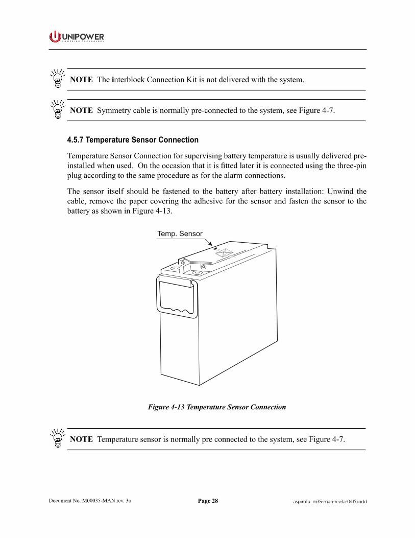
4.5.7 Temperature Sensor Connection
Temperature Sensor Connection for supervising battery temperature is usually delivered pre-installed when used. On the occasion that it is fitted later it is connected using the three-pin plug according to the same procedure as for the alarm connections.
The sensor itself should be fastened to the battery after battery installation: Unwind the cable, remove the paper covering the adhesive for the sensor and fasten the sensor to the battery as shown in Figure 4-13.
Temp. Sensor
Figure 4-13 Temperature Sensor Connection
NOTE Temperature sensor is normally pre connected to the system, see Figure 4-7.

Page 29
P O W E R I N G T E C H N O L O G Y
Document No. M00035-MAN rev. 3a aspiro1u_m35-man-rev3a-0417.indd
Chapter 5 Commissioning
5.1 Commissioning Overview
Before delivery the system was thoroughly inspected and tested. The following chapter is a guide to the set-up and operation of the control functions of the system.
NOTE Before starting commissioning read the product description for the individual components.
WARNING ONLY TECHNICAL STAFF WITH THE NECESSARY EXPERIENCE AND KNOWLEDGE, WITH REGARD TO THE POWER SUPPLY SUPPORT SYSTEM AND ITS BATTERIES, MAY PERFORM THE COMMISSIONING. IT IS IMPORTANT TO FOLLOW ALL SAFETY REGULATIONS.
If there are any difficulties in increasing the voltage to alarm level, the alarm level can be adjusted to a lower level.
5.2 Tools and Test Equipment
5.2.1 Tools List
The essential commissioning tools are listed in the Installation chapter.
5.2.2 Test Equipment
• Multimeter (3½ Digit, 0–1%DC)
• Load resistance, to fully load of two rectifiers
5.3 Preparation
Check the installation to ensure the following:
• Grounding: The equipment is correctly grounded. The grounding cable size, color and routing conform to the requirements.
• Power: The incoming mains AC power is available for this site. The site power switch and circuit breakers are clearly labeled. The power cables are correctly terminated.
• The site is clean and safe. Check that the system/cabinet is free of any unwanted objects or insects that may have got in during the installation.
Page 30
P O W E R I N G T E C H N O L O G Y
Document No. M00035-MAN rev. 3a aspiro1u_m35-man-rev3a-0417.indd
5.4 Commissioning procedure
1. Remove the covers and check that all connections are made according to the installation drawing. Verify that all connections are properly tightened with sufficient torque.
2. Ensure that load and battery MCB breakers are set to OFF position - ensuring the load and battery strings are connected.
3. Ensure that all rectifier modules are removed. If not, remove each one in turn starting from the rightmost position.
4. If the rectifier subrack has dip switches for addressing, verify that the dip switches are set correctly.
5. Check the battery polarity with the multimeter (3½ Digit, 0·1% dc). Place the positive lead of the meter to the positive busbar and the negative lead to the battery breaker. The meter must now show a positive voltage. If the voltage is negative, change over the connection of the blue and black battery cables to the batteries.
6. Turn on the AC mains voltage.
7. Measure the AC voltage on the AC terminal block between phases and neutral. The correct value is approximately 230V. If the value is different, check the AC connection.
8. Plug in all rectifier modules, starting from the leftmost position. Make sure to fasten the rectifiers again. The rectifiers will turn on automatically.
9. Set all load breakers into the “1” (ON) position.
10. Verify correct polarity on the battery connection by measuring the voltage drop across the battery breaker(s) (Normally not more than 5V DC).
11. The green LED on the controller should blink for approximately 20 sec.
12. The output voltage will increase slowly to U1 (float charge voltage).
13. Turn the battery breaker(s) to the “1” (ON) position.
14. If any alarms are present, they should be reset in accordance with the procedure for the installed controller, ACC or PCC.
15. The system should now be without alarms.
16. Attach all the system covers in their correct places.
17. Check that all changes to drawings, if any, have been completed.
18. Clean the site.
19. Fill in the commissioning record (see end of chapter).
Page 31
P O W E R I N G T E C H N O L O G Y
Document No. M00035-MAN rev. 3a aspiro1u_m35-man-rev3a-0417.indd
5.5 Test of output voltage
5.5.1 Float charge (U1)
Ensure that the controller is operating.
Connect a load, approx. 50% of total capacity, to the system.
Check the voltage according to the battery manufacturer’s requirements. If the batteries require a different float charging voltage, adjust the output voltage from the controller. (See the section for the appropriate controller)
If no change is required, use the following values:
Battery type Float charge Boost chargeOpen lead-acid batteries 2.23 V/Cell 2.33 V/CellValve regulated lead-acid batteries 2.27 V/Cell -
Table 5-1 Float/Boost Charge Voltages
5.5.2 Adjustment of Float Charge, U1
Unless otherwise ordered the default output voltage is factory pre-set to 53.5V. The total voltage has to be in accordance to the number of battery cells.
Please verify number of cells and the battery manufacturers requirement.
Adjust the output voltage from the control unit as necessary.
NOTE A seal protects the potentiometer in the subrack. Do not break the seal.
5.5.3 Boost charging (U2) (if applicable)
Open lead-acid batteries.
Automatic boost charging - calculation based on the time the battery voltage has been below certain levels. Automatic activating of boost charging for this calculated time multiplied by a (boost) factor.
Activate boost charging from the “Set/select U1-U4” menu in the controller.
Return to float charge manually by selecting “U1”, or automatically after a pre-set time.
VRLA batteries.
Most of the manufactures of valve regulated lead acid batteries do not recommend boost charging. If this type of battery is used, the boost function should be disabled.

Page 32
P O W E R I N G T E C H N O L O G Y
Document No. M00035-MAN rev. 3a aspiro1u_m35-man-rev3a-0417.indd
Boost charging figures
Observe and write down all of the boost charging figures. Parameters to be read/set/adjusted from control unit or PC with PowCom™ installed.
5.6 Battery supervision
For systems with symmetry cables supplied:
Set the number of battery strings according to the number of battery strings in the system. The settings are to be made in the control unit via a PC with PowCom™ installed or directly in the controller (if symmetry failure is indicated).
The symmetry fault alarm can be simulated by pulling out one symmetry cable from the battery string. Measure that setting to make sure that it is in accordance with the battery manufacturer’s recommendations.
For systems with temp. probe cable supplied:
Temperature compensation is factory pre-set. Check that the temp. probe is activated and verify that the compensation level is in accordance with the battery manufacturer’s requirements. (If no compensation level is available from the battery manufacture, UNIPOWER recommends that it is set to 0.5V).
5.7 Battery test
Settings should be made according to the battery manufacturer’s requirements, but as a rule of thumb the following settings can be used for standard VR lead batteries:
No. of test pr. year = 2
U3 Test = 1,9 V/cell
End voltage b.test = 1,94V/cell
Batt. test time = 40% of expected backup time
Ah limit for test = 40% of nominal battery capacity
Parameters should be set/adjusted from the controller (Battery test menu) or “Supervision - Set parameters” menu in PowCom™.
Page 33
P O W E R I N G T E C H N O L O G Y
Document No. M00035-MAN rev. 3a aspiro1u_m35-man-rev3a-0417.indd
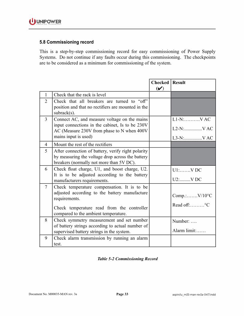
5.8 Commissioning record
This is a step-by-step commissioning record for easy commissioning of Power Supply Systems. Do not continue if any faults occur during this commissioning. The checkpoints are to be considered as a minimum for commissioning of the system.
Checked ()
Result
1 Check that the rack is level2 Check that all breakers are turned to “off”
position and that no rectifiers are mounted in the subrack(s).
3 Connect AC, and measure voltage on the mains input connections in the cabinet, Is to be 230V AC (Measure 230V from phase to N when 400V mains input is used)
L1-N:……….V AC
L2-N:...............V AC
L3-N:...............V AC4 Mount the rest of the rectifiers5 After connection of battery, verify right polarity
by measuring the voltage drop across the battery breakers (normally not more than 5V DC).
6 Check float charge, U1, and boost charge, U2. It is to be adjusted according to the battery manufacturers requirements.
U1:…….V DC
U2:.........V DC7 Check temperature compensation. It is to be
adjusted according to the battery manufacture requirements.
Check temperature read from the controller compared to the ambient temperature.
Comp.:…….V/10°C
Read off:………°C
8 Check symmetry measurement and set number of battery strings according to actual number of supervised battery strings in the system.
Number: ….
Alarm limit:……9 Check alarm transmission by running an alarm
test.
Table 5-2 Commissioning Record

Page 34
P O W E R I N G T E C H N O L O G Y
Document No. M00035-MAN rev. 3a aspiro1u_m35-man-rev3a-0417.indd
Chapter 6 Maintenance & Troubleshooting
6.1 Maintenance
Power system maintenance includes maintaining all parts of the system.
Annual maintenance should involve checking all connections on the terminals and circuit breakers. Output voltage should be verified to be within the acceptable limits at least once a year. Test results should be recorded and filed to see any deviations.
The power system requires periodic inspections and routine cleaning. It is very important to keep all areas and components of the system free from dust or other unwanted objects to ensure free air circulation and safe operation of the system.
CAUTION To undertake any further maintenance, strictly follow all manufacturer’s recommendations provided in the equipment manual.
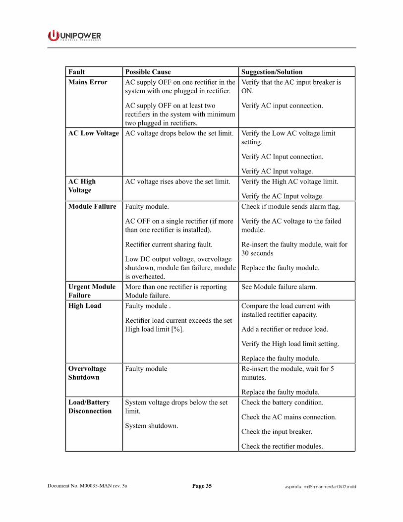
6.2 Troubleshooting
This troubleshooting chapter helps to determine the cause of the problem and suggests possible repair solutions. If the first step of the recommendation does not solve the problem continue to the next one.
NOTE If the malfunctioning of the system persists, please contact UNIPOWER technical support.
NOTE For a description of Alarms and Messages generated by the system controller see the Alarms/Messages section of the appropriate controller manual:
ACC Extended: http://www.unipowerco.com/pdf/acc-man.pdf PCC: http://www.unipowerco.com/pdf/pcc-man.pdf
By default, alarms are set to be indicated with a red light (higher priority) and messages with a yellow light (lower priority).
Fault Possible Cause Suggestion/SolutionLow System Voltage
Module failure.
Loss of AC power.
Load exceeds module capacity.
Replace faulty module.
Verify AC input connection.
Add module to system.High System Voltage
Module failure.
System voltage exceeds the set limit.
Replace the faulty module.
Check the High Voltage Alarm limit setting.
Page 35
P O W E R I N G T E C H N O L O G Y
Document No. M00035-MAN rev. 3a aspiro1u_m35-man-rev3a-0417.indd
Fault Possible Cause Suggestion/SolutionMains Error AC supply OFF on one rectifier in the
system with one plugged in rectifier.
AC supply OFF on at least two rectifiers in the system with minimum two plugged in rectifiers.
Verify that the AC input breaker is ON.
Verify AC input connection.
AC Low Voltage AC voltage drops below the set limit. Verify the Low AC voltage limit setting.
Verify AC Input connection.
Verify AC Input voltage.AC High Voltage
AC voltage rises above the set limit. Verify the High AC voltage limit.
Verify the AC Input voltage.Module Failure Faulty module.
AC OFF on a single rectifier (if more than one rectifier is installed).
Rectifier current sharing fault.
Low DC output voltage, overvoltage shutdown, module fan failure, module is overheated.
Check if module sends alarm flag.
Verify the AC voltage to the failed module.
Re-insert the faulty module, wait for 30 seconds
Replace the faulty module.
Urgent Module Failure
More than one rectifier is reporting Module failure.
See Module failure alarm.
High Load Faulty module .
Rectifier load current exceeds the set High load limit [%].
Compare the load current with installed rectifier capacity.
Add a rectifier or reduce load.
Verify the High load limit setting.
Replace the faulty module.Overvoltage Shutdown
Faulty module Re-insert the module, wait for 5 minutes.
Replace the faulty module.Load/Battery Disconnection
System voltage drops below the set limit.
System shutdown.
Check the battery condition.
Check the AC mains connection.
Check the input breaker.
Check the rectifier modules.
Page 36
P O W E R I N G T E C H N O L O G Y
Document No. M00035-MAN rev. 3a aspiro1u_m35-man-rev3a-0417.indd
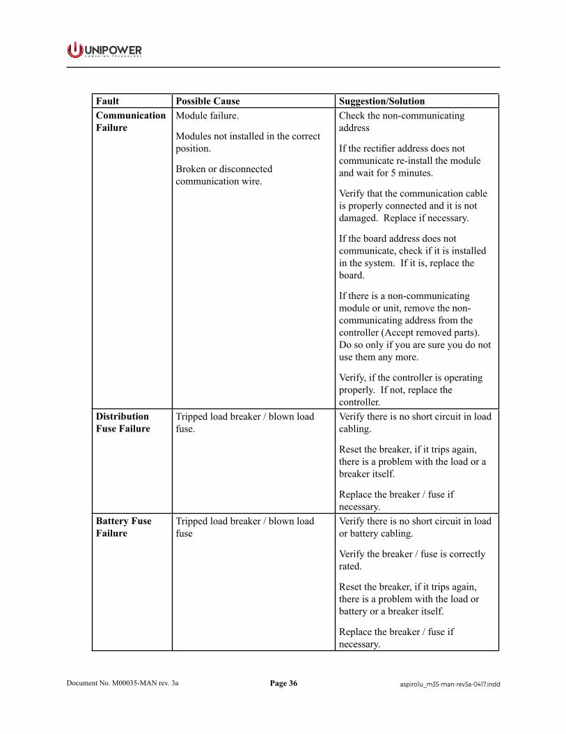
Fault Possible Cause Suggestion/SolutionCommunication Failure
Module failure.
Modules not installed in the correct position.
Broken or disconnected communication wire.
Check the non-communicating address
If the rectifier address does not communicate re-install the module and wait for 5 minutes.
Verify that the communication cable is properly connected and it is not damaged. Replace if necessary.
If the board address does not communicate, check if it is installed in the system. If it is, replace the board.
If there is a non-communicating module or unit, remove the non-communicating address from the controller (Accept removed parts). Do so only if you are sure you do not use them any more.
Verify, if the controller is operating properly. If not, replace the controller.
Distribution Fuse Failure
Tripped load breaker / blown load fuse.
Verify there is no short circuit in load cabling.
Reset the breaker, if it trips again, there is a problem with the load or a breaker itself.
Replace the breaker / fuse if necessary.
Battery Fuse Failure
Tripped load breaker / blown load fuse
Verify there is no short circuit in load or battery cabling.
Verify the breaker / fuse is correctly rated.
Reset the breaker, if it trips again, there is a problem with the load or battery or a breaker itself.
Replace the breaker / fuse if necessary.
Page 37
P O W E R I N G T E C H N O L O G Y
Document No. M00035-MAN rev. 3a aspiro1u_m35-man-rev3a-0417.indd
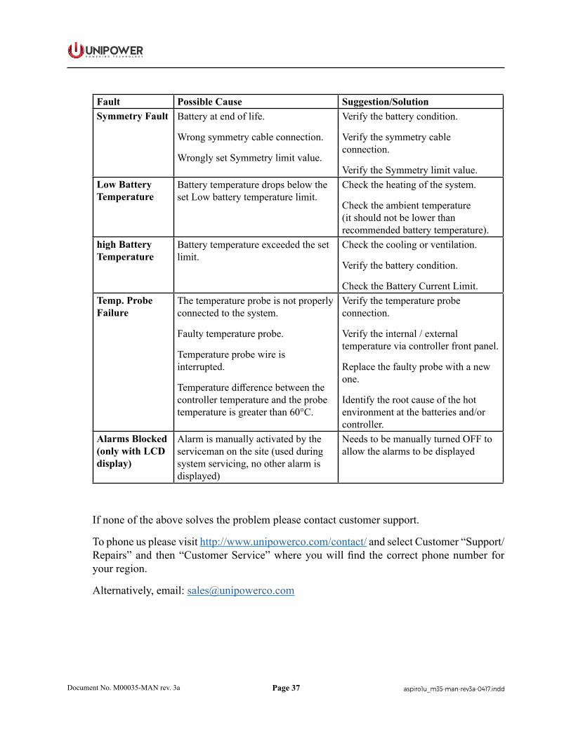
Fault Possible Cause Suggestion/SolutionSymmetry Fault Battery at end of life.
Wrong symmetry cable connection.
Wrongly set Symmetry limit value.
Verify the battery condition.
Verify the symmetry cable connection.
Verify the Symmetry limit value.Low Battery Temperature
Battery temperature drops below the set Low battery temperature limit.
Check the heating of the system.
Check the ambient temperature (it should not be lower than recommended battery temperature).
high Battery Temperature
Battery temperature exceeded the set limit.
Check the cooling or ventilation.
Verify the battery condition.
Check the Battery Current Limit.Temp. Probe Failure
The temperature probe is not properly connected to the system.
Faulty temperature probe.
Temperature probe wire is interrupted.
Temperature difference between the controller temperature and the probe temperature is greater than 60°C.
Verify the temperature probe connection.
Verify the internal / external temperature via controller front panel.
Replace the faulty probe with a new one.
Identify the root cause of the hot environment at the batteries and/or controller.
Alarms Blocked (only with LCD display)
Alarm is manually activated by the serviceman on the site (used during system servicing, no other alarm is displayed)
Needs to be manually turned OFF to allow the alarms to be displayed
If none of the above solves the problem please contact customer support.
To phone us please visit http://www.unipowerco.com/contact/ and select Customer “Support/Repairs” and then “Customer Service” where you will find the correct phone number for your region.
Alternatively, email: [email protected]

Page 38
P O W E R I N G T E C H N O L O G Y
Document No. M00035-MAN rev. 3a aspiro1u_m35-man-rev3a-0417.indd
Chapter 7 Replacing Modules
7.1 Controller Replacement
A faulty Controller can be easily replaced with a new one:
1. Loosen the front screw in the top left corner of the controller front panel using a flat screwdriver, see Figure 7-1.
Figure 7-1 Unlocking the Controller
2. Pull the controller out of the shelf as shown in Figure 7-2.
Figure 7-2 Removing the Controller
3. Reverse the process to insert the new controller into the empty slot and fasten the screw.
CAUTION After controller start-up, verify if the appropriate configuration file is uploaded to the controller. If necessary refer to the PowCom™ User Guide.
Page 39
P O W E R I N G T E C H N O L O G Y
Document No. M00035-MAN rev. 3a aspiro1u_m35-man-rev3a-0417.indd
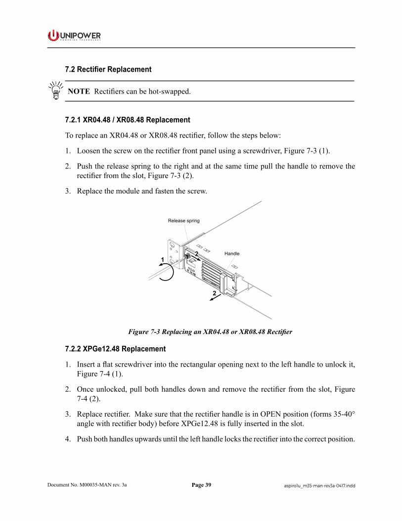
7.2 Rectifier Replacement
NOTE Rectifiers can be hot-swapped.
7.2.1 XR04.48 / XR08.48 Replacement
To replace an XR04.48 or XR08.48 rectifier, follow the steps below:
1. Loosen the screw on the rectifier front panel using a screwdriver, Figure 7-3 (1).
2. Push the release spring to the right and at the same time pull the handle to remove the rectifier from the slot, Figure 7-3 (2).
3. Replace the module and fasten the screw.
Release spring
Handle1
2
2
Figure 7-3 Replacing an XR04.48 or XR08.48 Rectifier
7.2.2 XPGe12.48 Replacement
1. Insert a flat screwdriver into the rectangular opening next to the left handle to unlock it, Figure 7-4 (1).
2. Once unlocked, pull both handles down and remove the rectifier from the slot, Figure 7-4 (2).
3. Replace rectifier. Make sure that the rectifier handle is in OPEN position (forms 35-40° angle with rectifier body) before XPGe12.48 is fully inserted in the slot.
4. Push both handles upwards until the left handle locks the rectifier into the correct position.

Page 40
P O W E R I N G T E C H N O L O G Y
Document No. M00035-MAN rev. 3a aspiro1u_m35-man-rev3a-0417.indd
1 2
Figure 7-3 Replacing an XPGe12.48 Rectifier
CAUTION After rectifier rebooting, check that the green LED is lit.
7.3 Breaker Replacement
WARNING Make sure the system is switched OFF.
To replace a faulty circuit breaker, follow the steps below:
1. Remove the top cover by loosening 4 screws on each side of the system and one screw at the rear, see Figure 7-5.
Figure 7-5 Top Cover Removal

Page 41
P O W E R I N G T E C H N O L O G Y
Document No. M00035-MAN rev. 3a aspiro1u_m35-man-rev3a-0417.indd
This document is believed to be correct at time of publication and UNIPOWER LLC accepts no responsibility for consequences from printing errors or inaccuracies. Specifications are subject to change without notice.
2. Pull the Faston connector from the circuit breaker, see detail in Figure 7-6 (1).
3. Press the top and bottom of the breaker, Figure 7-6 (2) to disengage it from its place and pull it out, Figure 7-7.
1
1
2
2
Figure 7-6 Breaker Removal - A
Figure 7-7 Breaker Removal - B
4. Snap in a new breaker of the same type.
5. Plug the Faston connector to the breaker.
6. Re-attach the top cover.
Page 42
P O W E R I N G T E C H N O L O G Y
Document No. M00035-MAN rev. 3a aspiro1u_m35-man-rev3a-0417.indd
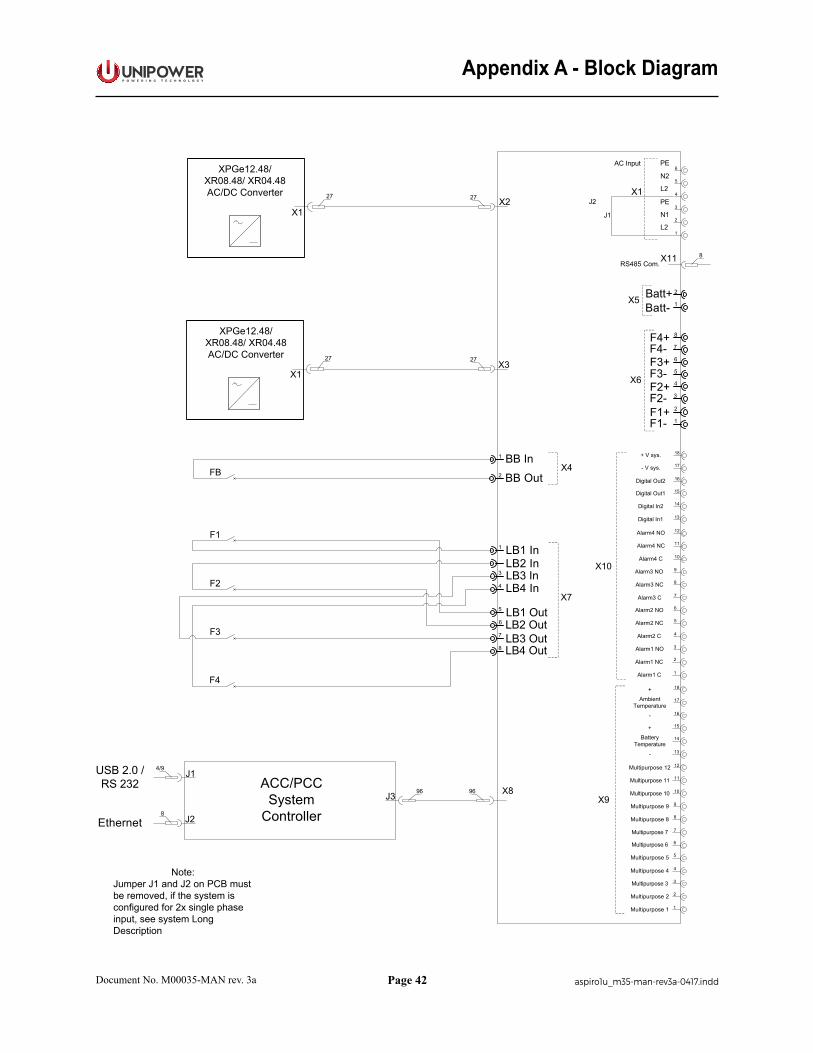
Appendix A - Block Diagram
6
5
4
3
2
1
Multipurpose 5
Multipurpose 3
Multipurpose 1
Multipurpose 6
Multipurpose 4
Multipurpose 2
FB
F1
F2
F3
F4
12
11
10
9
8
7
Multipurpose 11
Multipurpose 9
Multipurpose 7
Multipurpose 12
Multipurpose 10
Multipurpose 8
15
14
13
BatteryTemperature
+
-
18
17
16
AmbientTemperature
+
-
6
5
4
3
2
1
Alarm2 NC
Alarm1 NO
Alarm1 C
Alarm2 NO
Alarm2 C
Alarm1 NC
12
11
10
9
8
7
Alarm4 NC
Alarm3 NO
Alarm3 C
Alarm4 NO
Alarm4 C
Alarm3 NC
15
14
13
Digital In2
Digital Out1
Digital In1
18
17
16
- V sys.
+ V sys.
Digital Out2
X9
X10
F1+F1-
F2-
F3-
F4-
F2+
F3+
F4+ 8
7
6
5
4
3
2
1
X6
2
1Batt-Batt+X5
L2
PE
N1
L2
PE
N2
X1
6
5
4
3
2
1
LB3 OutLB4 Out
LB2 Out
LB4 In
LB2 In
LB1 Out
LB3 In
LB1 In1
3
4
5
6
7
8
X7
1
2 BB Out
BB InX4
96
27
27
X1
27
X1
27
X2
X3
USB 2.0 /RS 232 ACC/PCC
SystemControllerJ2
8
96
J1
J3
Ethernet
4/9
J1
J2
X8
8X11RS485 Com.
AC InputXPGe12.48/
XR08.48/ XR04.48AC/DC Converter
XPGe12.48/XR08.48/ XR04.48AC/DC Converter
Note:Jumper J1 and J2 on PCB must be removed, if the system is configured for 2x single phase input, see system Long Description
Page 43
P O W E R I N G T E C H N O L O G Y
Document No. M00035-MAN rev. 3a aspiro1u_m35-man-rev3a-0417.indd
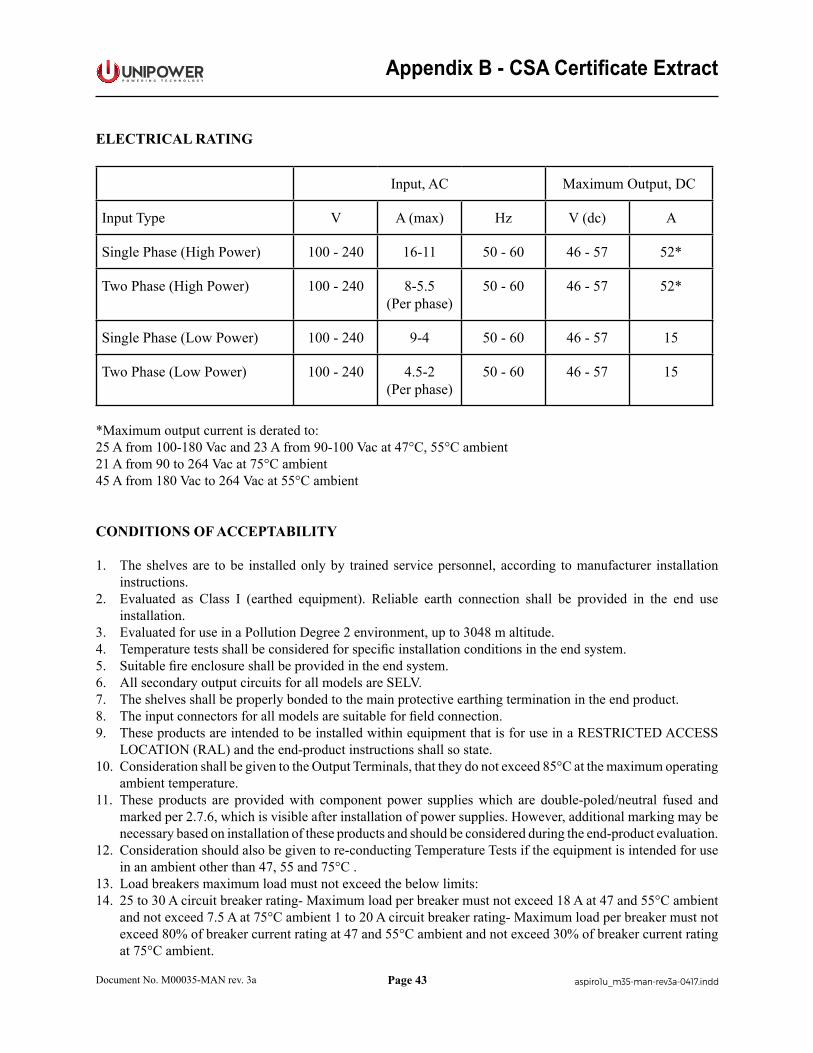
Appendix B - CSA Certificate Extract
ELECTRICAL RATING
Input, AC Maximum Output, DC
Input Type V A (max) Hz V (dc) A
Single Phase (High Power) 100 - 240 16-11 50 - 60 46 - 57 52*
Two Phase (High Power) 100 - 240 8-5.5(Per phase)
50 - 60 46 - 57 52*
Single Phase (Low Power) 100 - 240 9-4 50 - 60 46 - 57 15
Two Phase (Low Power) 100 - 240 4.5-2(Per phase)
50 - 60 46 - 57 15
*Maximum output current is derated to:25 A from 100-180 Vac and 23 A from 90-100 Vac at 47°C, 55°C ambient21 A from 90 to 264 Vac at 75°C ambient45 A from 180 Vac to 264 Vac at 55°C ambient
CONDITIONS OF ACCEPTABILITY
1. The shelves are to be installed only by trained service personnel, according to manufacturer installation instructions.
2. Evaluated as Class I (earthed equipment). Reliable earth connection shall be provided in the end use installation.
3. Evaluated for use in a Pollution Degree 2 environment, up to 3048 m altitude.4. Temperature tests shall be considered for specific installation conditions in the end system.5. Suitable fire enclosure shall be provided in the end system.6. All secondary output circuits for all models are SELV.7. The shelves shall be properly bonded to the main protective earthing termination in the end product.8. The input connectors for all models are suitable for field connection.9. These products are intended to be installed within equipment that is for use in a RESTRICTED ACCESS
LOCATION (RAL) and the end-product instructions shall so state.10. Consideration shall be given to the Output Terminals, that they do not exceed 85°C at the maximum operating
ambient temperature.11. These products are provided with component power supplies which are double-poled/neutral fused and
marked per 2.7.6, which is visible after installation of power supplies. However, additional marking may be necessary based on installation of these products and should be considered during the end-product evaluation.
12. Consideration should also be given to re-conducting Temperature Tests if the equipment is intended for use in an ambient other than 47, 55 and 75°C .
13. Load breakers maximum load must not exceed the below limits:14. 25 to 30 A circuit breaker rating- Maximum load per breaker must not exceed 18 A at 47 and 55°C ambient
and not exceed 7.5 A at 75°C ambient 1 to 20 A circuit breaker rating- Maximum load per breaker must not exceed 80% of breaker current rating at 47 and 55°C ambient and not exceed 30% of breaker current rating at 75°C ambient.
Page 44
P O W E R I N G T E C H N O L O G Y
Document No. M00035-MAN rev. 3a aspiro1u_m35-man-rev3a-0417.indd
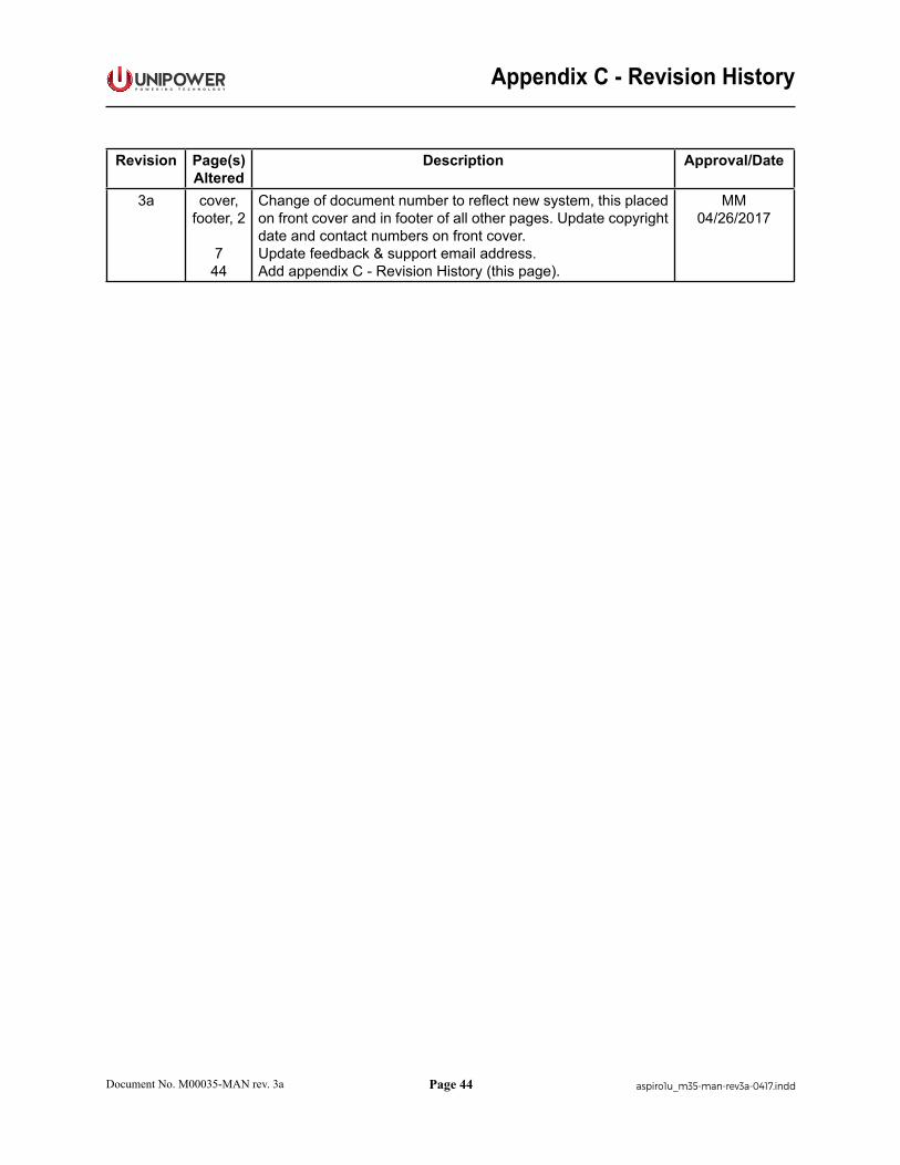
Appendix C - Revision History
Revision Page(s) Altered
Description Approval/Date
3a cover, footer, 2
744
Change of document number to reflect new system, this placed on front cover and in footer of all other pages. Update copyright date and contact numbers on front cover.Update feedback & support email address.Add appendix C - Revision History (this page).
MM04/26/2017