power system stability analysis by applying pss in etap · in etap the udm is inbuilt, by which we...
TRANSCRIPT
Power System Stability Analysis By
Applying PSS in ETAP
A Project report submitted in partial fulfillment
of the requirements for the degree of B. Tech in Electrical Engineering
By
Pranay Paria (11701615064)
Sarbamangala Ray (11701615066)
Somnath Paul (11701615068)
Sayantan Choudhury (11701614040)
Under the supervision of
Dr. Debasish Mondal
(Associate Professor)
Dept. of Electrical Engineering
Department of Electrical Engineering
RCC INSTITUTE OF INFORMATION TECHNOLOGY
CANAL SOUTH ROAD, BELIAGHATA, KOLKATA – 700015, WEST BENGAL
Maulana Abul Kalam Azad University of Technology (MAKAUT)
© 2018
:Table of Contents:
Page no:
Certificate (i)
Acknowledgement (ii)
0Abstract (iii)
CHAPTER 1: Introduction
1.1 Literature review 1
1.2 Objective of the project work 2
CHAPTER 2: Theoretical Overview
2.1 Summery of ETAP 3
2.2 Theory of transient stability analysis 4-7
2.3 Overview of PSS 8-19
2.4 Overview of UDM 10
CHAPTER 3: System Study and Implementation
3.1 Schematic diagram of proposed system 11
3.2 Transient stability analysis steps in ETAP 12-21
3.3 Study of Transient stability characteristics of the system 22-24
CHAPTER 4: Conclusion & Future Scope of work
4.1 Conclusion 25
4.2 Future Scope 26
References 27
List Of Figures: Page no:
Fig 2.2.1: Characteristics of stability vs Time 5
Fig 2.2.2: Critical area vs Time 7
Fig 2.3.1: PSS block diagram 8
Fig 2.3.2: Functional block diagram of IEEE PSS1A 9
Fig 3.1.1: Schematic diagram of 4 bus system 11
Fig 3.3.1: Bus voltage angle vs Time without PSS 22
Fig 3.3.2: Bus voltage vs Time without PSS 22
Fig 3.3.3: Generator speed vs Time without PSS 22
Fig 3.3.4: Generator relative power angle vs Time without PSS 23
Fig 3.3.5: Bus voltage angle vs Time with PSS 23
Fig 3.3.6: Bus voltage vs Time with PSS 23
Fig 3.3.7: Generator speed vs Time with PSS 24
Fig 3.3.8: Generator relative power angle vs Time with PSS 24
List Of Table:
Table 3.3.9: Exciter gain vs PSS gain 24
CERTIFICATE
To whom it may concern
This is to certify that the project work entitled,‖ Power System Stability Analysis Applying PSS In
ETAP‖ is the bona fide work carried out by Pranay Paria (11701615064), Sarbamangala Ray
(11701615066), Somnath Paul (11701615068), Sayantan Choudhury (11701614040) a student of
B.Tech in the Dept. of Electrical Engineering, RCC Institute of Information Technology (RCCIIT),
Canal South Road, Beliaghata, Kolkata-700015, affiliated to Maulana Abul Kalam Azad University
of Technology (MAKAUT), West Bengal, India, during the academic year 2017-18, in partial
fulfillment of the requirements for the degree of Bachelor of Technology in Electrical Engineering
and that this project has not submitted previously for the award of any other degree, diploma and
fellowship.
_____________________ ________________________
Signature of the Guide Signature of the HOD
Name: Name:
Designation Designation
___________________________
Signature of the External Examiner
Name:
Designation:

ACKNOWLEDGEMENT
It is my great fortune that I have got opportunity to carry out this project work under the supervision
of Dr. Debasish Mondal in the Department of Electrical Engineering, RCC Institute of Information
Technology (RCCIIT), Canal South Road, Beliaghata, Kolkata-700015, affiliated to Maulana Abul
Kalam Azad University of Technology (MAKAUT), West Bengal, India. I express my sincere thanks
and deepest sense of gratitude to my guide for his constant support, unparalleled guidance and
limitless encouragement.
I wish to convey my gratitude to Prof. (Dr.) Alok Kole, HOD, Department of Electrical
Engineering, RCCIIT and to the authority of RCCIIT for providing all kinds of infrastructural facility
towards the research work.
I would also like to convey my gratitude to all the faculty members and staffs of the Department
of Electrical Engineering, RCCIIT for their whole-hearted cooperation to make this work turn into
reality.
-----------------------------------------------
Name and Signature of the Student
Place:
Date:
Abstract
This paper proposes Power System Stabilizer (PSS) in addition to the existing AVR
and Governor for Power System Stability. The variations of rotor angle, voltage and
frequency comparison parameter. The system is simulated with the existing for three phase
fault and single phase fault using ETAP software. The combination of AVR, Governor and
PSS maintains synchronism during all kind of faults.
Electric power system stability analysis has been recognized as an important and
challenging problem for secure system operation. When large disturbances occur in
interconnected power system, the security of this power system has to be examined. Power
system security depends on detailed stability studies of system to check and ensure security.
In order to determine the stability status of the power system for each contingency of any
disturbance occurs in power system.
Power system stability analysis may involve the calculation of critical clearing time
(CCT) for given fault which is defined as the maximum allowable value of the clearing time
for which the system remains to be stable. The power system shall remain stable if the fault is
cleared within this time. However, if the fault is cleared after the CCT, the power system is
most likely to become unstable. Thus, CCT estimation is important tusk in the transient
stability analysis for a given contingency.
Critical clearing time (CCT) in a way measure the power system transient stability. It
denotes the secure and safe time margin for clearing the contingency, usually three phase
ground fault. The larger value of CCT, the power system has sample time to clear the
contingency. CCT depends on generator inertias, line impedances, grid topology and power
system operating conditions, fault type and location. For a single machine infinite bus power
system, CCT calculation is straight forward. While for the case of multi machine power
system CCT is always obtained by repeating time domain simulation.
CHAPTER 1: Introduction:
1.1:LITERATURE REVIEW:
Normally power system is running with stabilized operation. When sudden change in
load any kind of earth fault occurs then the stabilization comes to the system. Basically,
stabilization means the change in angle between stator and rotor angle & also the change in
speed of the machine.
ETAP is the most comprehensive analysis platform for the design, simulation,
operation and automation of generation, distribution, and industrial power system. ETAP
is developed under an established quality assurance program and is use worldwide as a
high impact software. It is completely localized in four languages with translated output
reports in six languages ETAP is the Simulink software where we can draw a system. By
using Power System Stabilizer, we can reduce the instability by providing signal to rotor.
In the given project, ―Power System Stability Analysis by Applying PSS in ETAP‖
we study the whole project work from different references. These are-
The abstract are help from C. L. Wadha , ―Electrical Power System‖ where the PSS
are existing AVR and governor for power system stability and the system is simulated
#phase and 1 phase fault by using ETAP. The PSS analysis may involve the calculation of
critical clearing time (CCT) which define as the maximum allowable value for clearing
time of fault and system remain stable.
The whole ETAP software are learn and study from ― ETAP power station user guide‖
and also User Define Dynamic model(UDM) studied, chapter 20.
The Power System Stability Analysis and Control are studied and guided us about PSS
from- P. Kundur, ―Power System Stability & Control‖, Mc Graw Hill.inc
The schematic diagram are inbuilt in the ETAP software and we analysis the transient
stability of synchronous generation related this project from F. Selwa, L. Djmel, ―Transient
Stability Analysis of Synchronous Generation of Electrical Work‖.
The study of overall project with help of ETAP manual, ETAP AUTOMATION
PRIVATE LTD INDIA its available at RCCIIT, EE, APJ Abdul Kalam Inovation Centre.
1.2:OBJECTIVE OF THE PROJECT WORK:
The main objective of PSS is to damp out oscillations, it can have strong effect on
power system transient stability. As, PSS damps oscillation by regulating generator field
voltage it results in swing of VAR output. So the PSS gain is chosen carefully, so that the
resultant gain margin of volt/VAR swing should be acceptable. A control enhancement
may be needed during the loading/unloading or loss of generation when large
fluctuations in the frequency and speed may act through the PSS and drive the system
towards in stability. A modified limit logic will allow this limits to be minimized while
ensuring the damping action of PSS for all other system events.
Another aspects of PSS which needs attention is possible interaction with other
controls which may be part of the excitation system or external system. Apart from the
low frequency oscillation the input of PSS also contains high frequency turbine
generator oscillation which should be taken into account for the PSS design. So
emphasis should be on the study of potential of PSS-torsional interaction and verify the
conclusion before commission of PSS.
CHAPTER 2: Theoretical Overview
2.1:SUMMARY OF ETAP:
ETAP stands for Electrical Transient Analysis Program. It is Simulink base software like as
MATLAB. A system is designed into the software and then if any fault or any kind of change occurs
into the system then we check the load flow diagram. After implementing the system, we have to set
the fault time, fault clearing time, and we see the transient stability analysis. In ETAP the UDM is
inbuilt, by which we create individual block diagram for exciter, PSS, governor.
ETAP is a full spectrum analytical engineering software specializing in the analysis, simulation
monitoring, control, optimization and automation of electrical power system. ETAP software offers
the best and most comprehensive suite of integrated power system from modeling to operation. It
mainly used in generation transmission distribution, industrial, transportation, low voltage etc. sectors.
For power generation system critical design and analysis to a smooth operation. From renewable
to nuclear, some of the world most advance power generation plants count on ETAP to help provide
reliable, clean and cost-effective power to their customer.
ETAP software mostly used in power transmission system mostly integrated transmission
network planning and their protection & energy management solution. ETAP grid transmission
system software integrates transmission network planning with there detail substation models,
network topology processing, transmission system analysis and real time transmission network energy
management system, electric SCADA etc.
ETAP grid offers distribution network analysis operation solution on a progressive geospatial
platform for simulating and optimizing the performance of smart grid and micro grid also. It also
practical application on industrial transportation and low voltage area also.
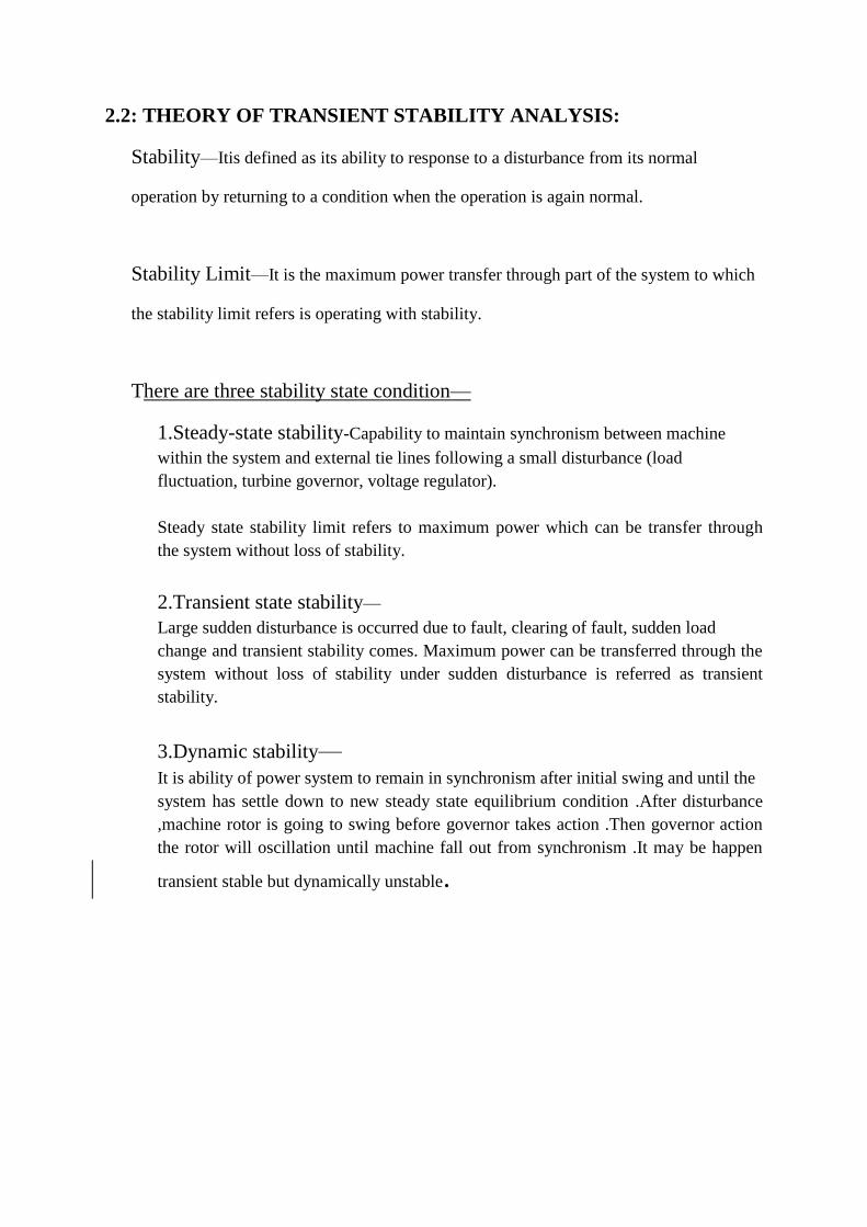
2.2: THEORY OF TRANSIENT STABILITY ANALYSIS:
Stability—Itis defined as its ability to response to a disturbance from its normal
operation by returning to a condition when the operation is again normal.
Stability Limit—It is the maximum power transfer through part of the system to which
the stability limit refers is operating with stability.
There are three stability state condition—
1.Steady-state stability-Capability to maintain synchronism between machine
within the system and external tie lines following a small disturbance (load
fluctuation, turbine governor, voltage regulator).
Steady state stability limit refers to maximum power which can be transfer through
the system without loss of stability.
2.Transient state stability—
Large sudden disturbance is occurred due to fault, clearing of fault, sudden load
change and transient stability comes. Maximum power can be transferred through the
system without loss of stability under sudden disturbance is referred as transient
stability.
3.Dynamic stability— It is ability of power system to remain in synchronism after initial swing and until the
system has settle down to new steady state equilibrium condition .After disturbance
,machine rotor is going to swing before governor takes action .Then governor action
the rotor will oscillation until machine fall out from synchronism .It may be happen
transient stable but dynamically unstable.
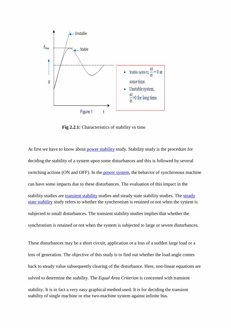
Fig 2.2.1: Characteristics of stability vs time
At first we have to know about power stability study. Stability study is the procedure for
deciding the stability of a system upon some disturbances and this is followed by several
switching actions (ON and OFF). In the power system, the behavior of synchronous machine
can have some impacts due to these disturbances. The evaluation of this impact in the
stability studies are transient stability studies and steady state stability studies. The steady
state stability study refers to whether the synchronism is retained or not when the system is
subjected to small disturbances. The transient stability studies implies that whether the
synchronism is retained or not when the system is subjected to large or severe disturbances.
These disturbances may be a short circuit, application or a loss of a sudden large load or a
loss of generation. The objective of this study is to find out whether the load angle comes
back to steady value subsequently clearing of the disturbance. Here, non-linear equations are
solved to determine the stability. The Equal Area Criterion is concerned with transient
stability. It is in fact a very easy graphical method used. It is for deciding the transient
stability of single machine or else two-machine system against infinite bus.
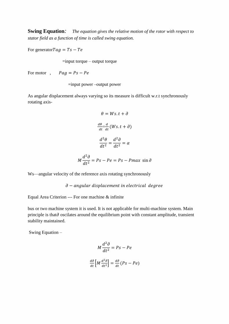
Swing Equation: The equation gives the relative motion of the rotor with respect to
stator field as a function of time is called swing equation.
For generator
=input torque – output torque
For motor ,
=input power –output power
As angular displacement always varying so its measure is difficult w.r.t synchronously
rotating axis-
=
Ws—angular velocity of the reference axis rotating synchronously
Equal Area Criterion --- For one machine & infinite
bus or two machine system it is used. It is not applicable for multi-machine system. Main
principle is that oscilates around the equilibrium point with constant amplitude, transient
stability maintained.
Swing Equation –
[
]
)
∫
Before & after disturbance,
∫
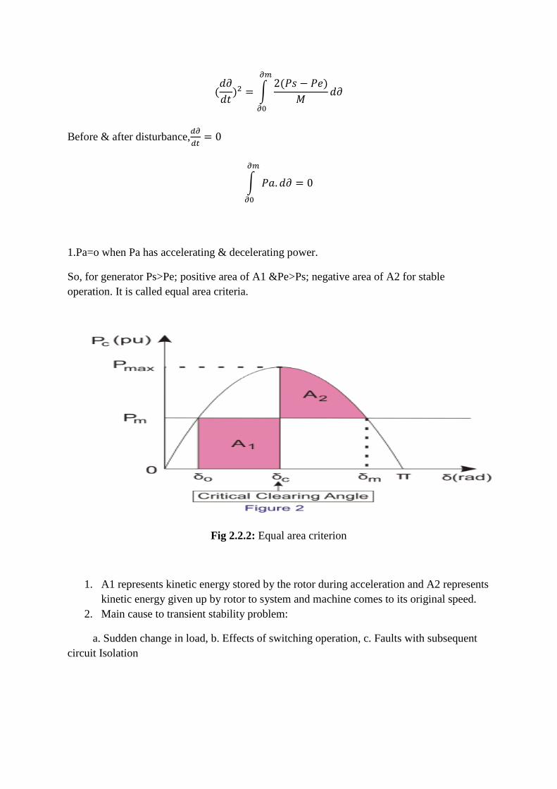
1.Pa=o when Pa has accelerating & decelerating power.
So, for generator Ps>Pe; positive area of A1 &Pe>Ps; negative area of A2 for stable
operation. It is called equal area criteria.
Fig 2.2.2: Equal area criterion
1. A1 represents kinetic energy stored by the rotor during acceleration and A2 represents
kinetic energy given up by rotor to system and machine comes to its original speed.
2. Main cause to transient stability problem:
a. Sudden change in load, b. Effects of switching operation, c. Faults with subsequent
circuit Isolation
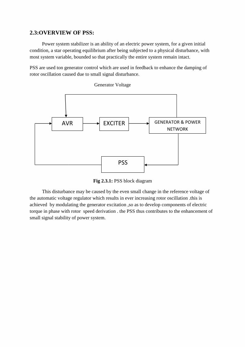
2.3:OVERVIEW OF PSS:
Power system stabilizer is an ability of an electric power system, for a given initial
condition, a star operating equilibrium after being subjected to a physical disturbance, with
most system variable, bounded so that practically the entire system remain intact.
PSS are used ton generator control which are used in feedback to enhance the damping of
rotor oscillation caused due to small signal disturbance.
Generator Voltage
Fig 2.3.1: PSS block diagram
This disturbance may be caused by the even small change in the reference voltage of
the automatic voltage regulator which results in ever increasing rotor oscillation .this is
achieved by modulating the generator excitation ,so as to develop components of electric
torque in phase with rotor speed derivation . the PSS thus contributes to the enhancement of
small signal stability of power system.
AVR EXCITER GENERATOR & POWER
NETWORK
PSS
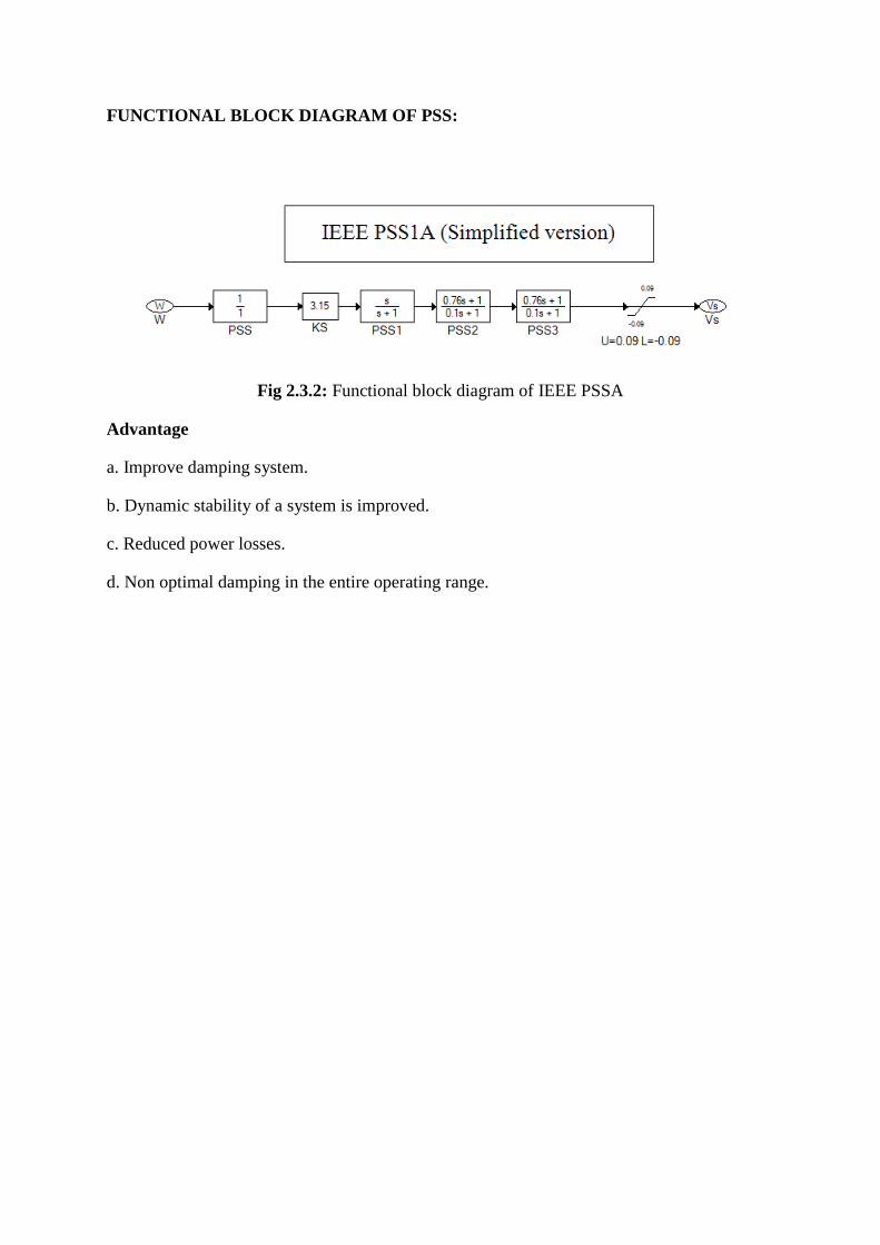
FUNCTIONAL BLOCK DIAGRAM OF PSS:
Fig 2.3.2: Functional block diagram of IEEE PSSA
Advantage
a. Improve damping system.
b. Dynamic stability of a system is improved.
c. Reduced power losses.
d. Non optimal damping in the entire operating range.

2.4:OVERVIEW OF UDM:
UDM stands for User Defined Dynamic Models. It has three steps for completing the
work. It is the tools to link up defined governor, exciter, PSS. The steps are-
A. Create UDM template file.
B. Create UDM equation file.
C. Power system transient stability models.
Using block diagram first make the models of individuals, then save it and change the
parameter. After compiling the models of UDM equation will be generate. When we build a
system any power station then we see the transient characteristics.
Custom Block Diagram Of UDM
A. Automatic voltage regulator(AVR)
B. Power system stabilizer(PSS)
C. Generator exciter
D. Turbines/Engines
E. Speed governors/Controllers
F. Photovoltaic array
UDM Capabilities
A. Transient stability
B. Generator start-up
C. Motor acceleration
D. Synchronous motor start up
E. Frequency dependent models
F. Bus voltage support mode
CHAPTER 3: System Study and Implementation
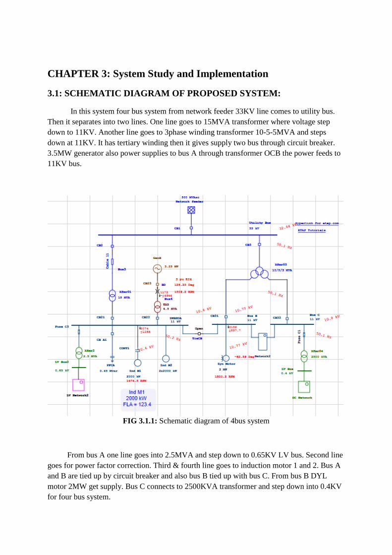
3.1: SCHEMATIC DIAGRAM OF PROPOSED SYSTEM:
In this system four bus system from network feeder 33KV line comes to utility bus.
Then it separates into two lines. One line goes to 15MVA transformer where voltage step
down to 11KV. Another line goes to 3phase winding transformer 10-5-5MVA and steps
down at 11KV. It has tertiary winding then it gives supply two bus through circuit breaker.
3.5MW generator also power supplies to bus A through transformer OCB the power feeds to
11KV bus.
FIG 3.1.1: Schematic diagram of 4bus system
From bus A one line goes into 2.5MVA and step down to 0.65KV LV bus. Second line
goes for power factor correction. Third & fourth line goes to induction motor 1 and 2. Bus A
and B are tied up by circuit breaker and also bus B tied up with bus C. From bus B DYL
motor 2MW get supply. Bus C connects to 2500KVA transformer and step down into 0.4KV
for four bus system.
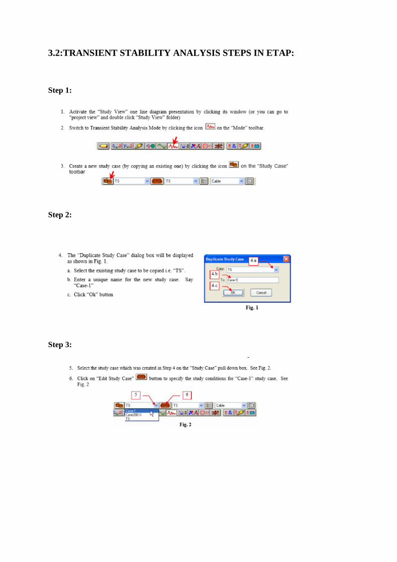
3.2:TRANSIENT STABILITY ANALYSIS STEPS IN ETAP:
Step 1:
Step 2:
Step 3:
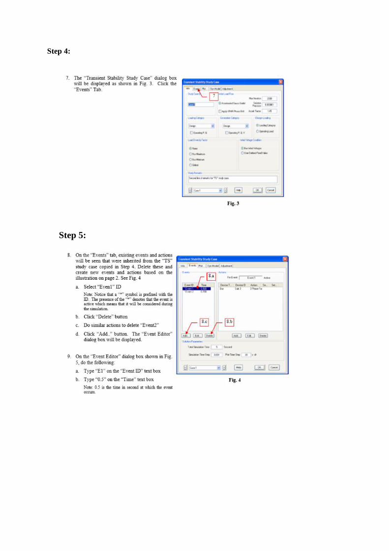
Step 4:
Step 5:
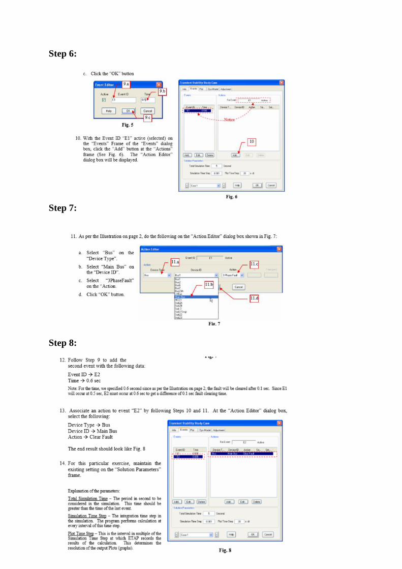
Step 6:
Step 7:
Step 8:
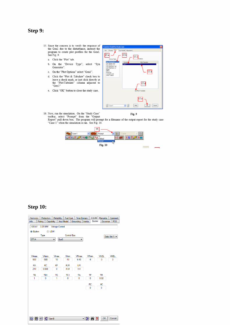
Step 9:
Step 10:
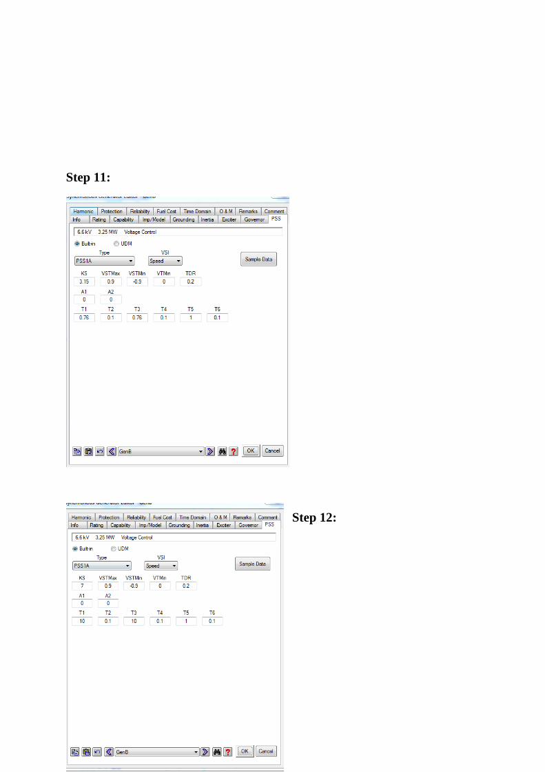
Step 11:
Step 12:
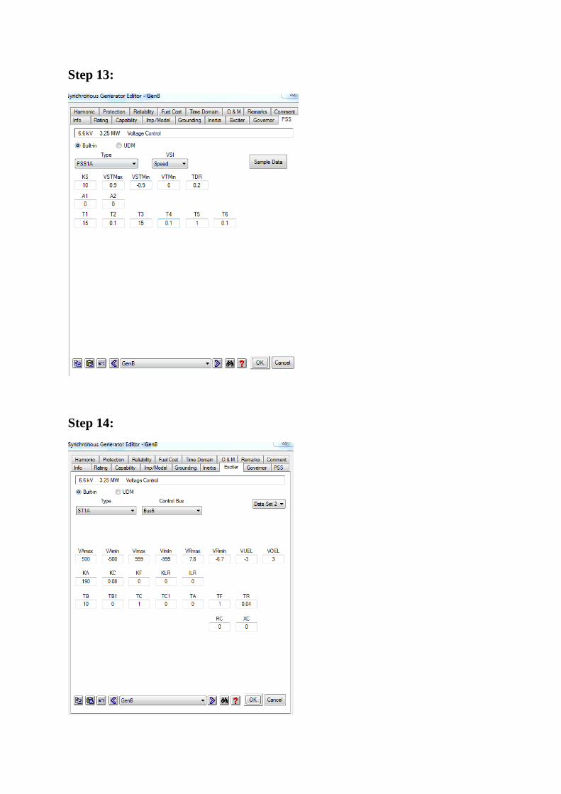
Step 13:
Step 14:
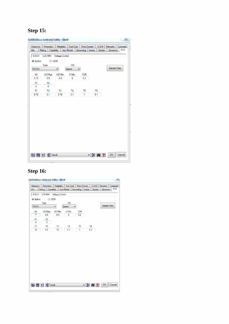
Step 15:
Step 16:
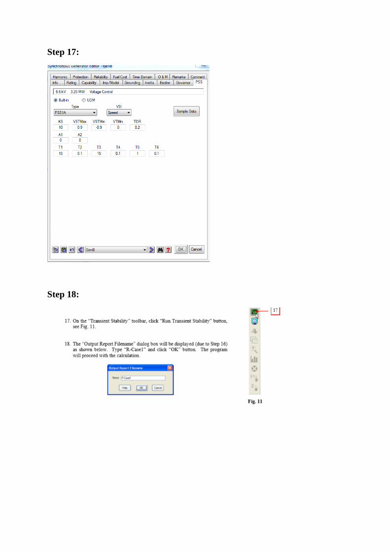
Step 17:
Step 18:
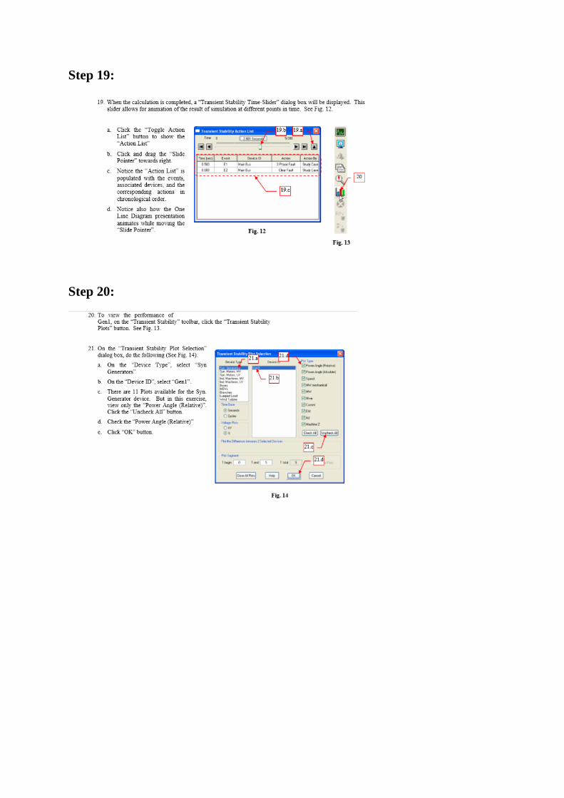
Step 19:
Step 20:
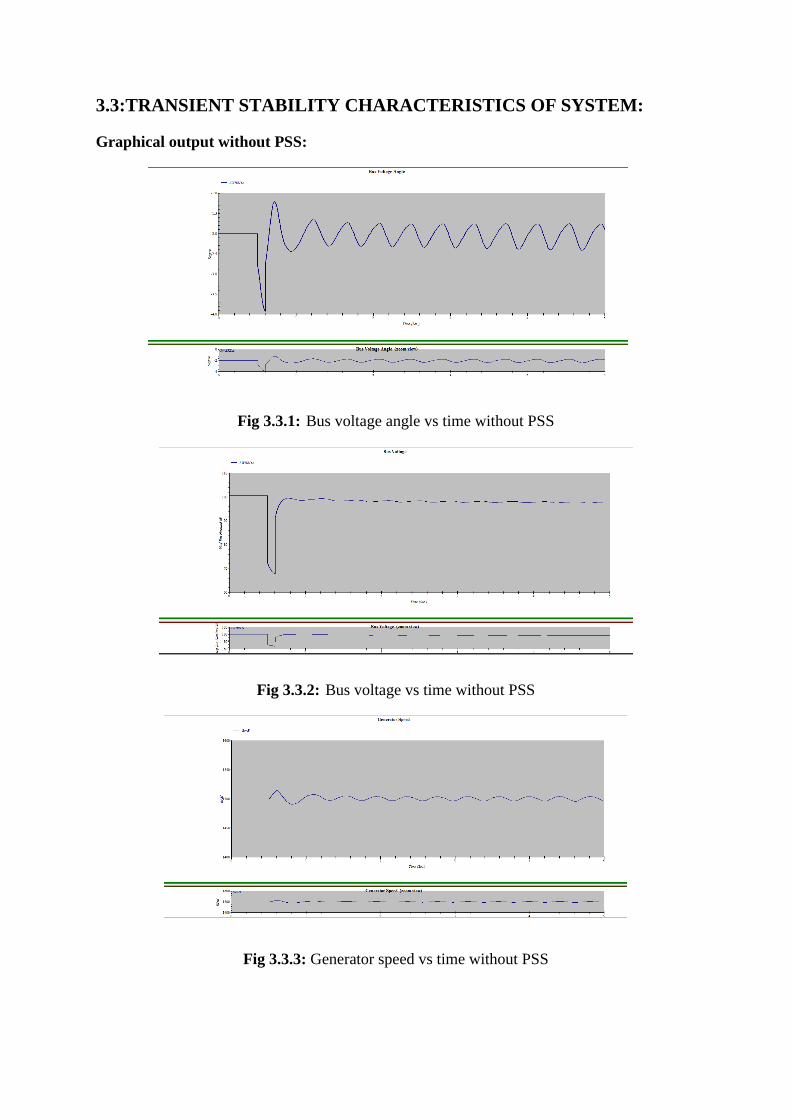
3.3:TRANSIENT STABILITY CHARACTERISTICS OF SYSTEM:
Graphical output without PSS:
Fig 3.3.1: Bus voltage angle vs time without PSS
Fig 3.3.2: Bus voltage vs time without PSS
Fig 3.3.3: Generator speed vs time without PSS
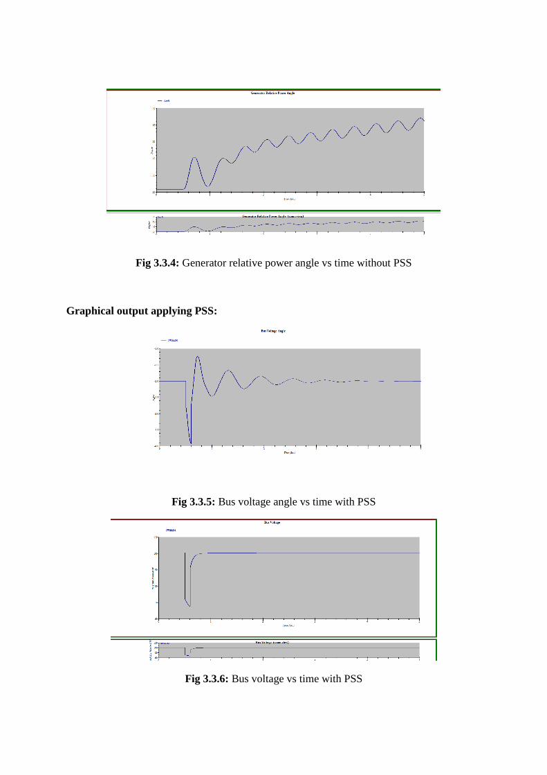
Fig 3.3.4: Generator relative power angle vs time without PSS
Graphical output applying PSS:
Fig 3.3.5: Bus voltage angle vs time with PSS
Fig 3.3.6: Bus voltage vs time with PSS
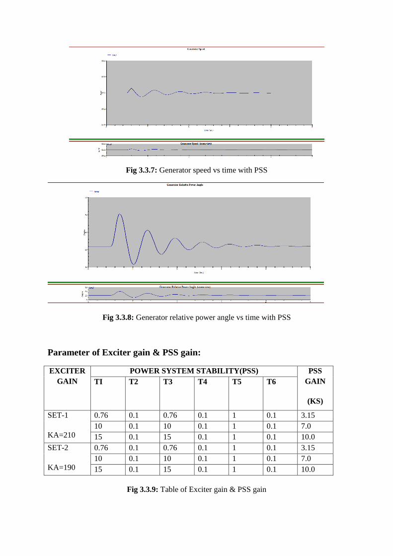
Fig 3.3.7: Generator speed vs time with PSS
Fig 3.3.8: Generator relative power angle vs time with PSS
Parameter of Exciter gain & PSS gain:
EXCITER
GAIN
POWER SYSTEM STABILITY(PSS) PSS
GAIN
(KS)
TI T2 T3 T4 T5 T6
SET-1
KA=210
0.76 0.1 0.76 0.1 1 0.1 3.15
10 0.1 10 0.1 1 0.1 7.0
15 0.1 15 0.1 1 0.1 10.0
SET-2
KA=190
0.76 0.1 0.76 0.1 1 0.1 3.15
10 0.1 10 0.1 1 0.1 7.0
15 0.1 15 0.1 1 0.1 10.0
Fig 3.3.9: Table of Exciter gain & PSS gain
4.1: CONCLUSION:
In this project the transient stability analysis has been performed on ETAP software.
An ANSI.IES study system has been taken into consideration to study the transient stability
characteristics of the system. Performance of the system has been investigated for typical
false scenarios. A user define model of PSS is incorporated with a specific generator bus to
improve the transient stability performance of the system. The simulation has been carried
out for the parameters; generator speed, generator relative power angle, bus voltage, bus
voltage angle without and with PSS. It has been observed that without PSS the response of
the system parameters is oscillatory and some cases unstable in nature due to the effect of
fault. However, with application of PSS oscillatory nature of the parameters are reduced and
reaches stable and steady state position. PSS not only reduces overshoot and undershoot in
response but also quickly brings the system
4.2: FUTURE SCOPE:
Power system stability analysis by applying PSS in ETAP the future scope is
verification of the ETAP model and update the as built study as require and also verify the
protection relay setting and co ordination study. Final recommendation of arc flash study to
be implemented. The analysis shall consist of the following-
A. Data collection
B. System modeling
C. Mode verification & validation
D. Fault & device duty evaluation study
E. Protective device coordination study
F. Arc flash hazard assessment
G. Project deliverables including detail report of findings &
recommendation
REFERENCE:
1. ETAP manual, ETAP AUTOMATION PVT. LTD. INDIA ,Available in RCCIIT,
EE,APJ Abdul Kalam Innovation Center, RCCIIT R&D Cell.
2. J. S. Patel & M. N. Sinha, ― Power System Transient Stability Analysis Using ETAP
Software‖, National conference on recent Trends in Engineering and Technology, May
2011
3. ETAP Power station user guide, User-Defined Dynamic Model, chapter 20
4. PETER W. & M. A. Pai ,‖ Power System Dynamics‖, Prentice Hall. Inc,1998.
5. P. Kundur , M. Klein, G. J Rogers & M. S Zywno, ―Application of Power System
Stabilizer for Enhancement of overall System Stability‖, IEEE Trans. On Power system
vol.4, No.2 ,PP 614-626,May 1989.
6. P. Kundur, ―Power System Stability & Control‖, Mc Graw Hill ,Inc, 1994.
7. F. Selwa , L. Djamel, ―Transient Stability Analysis of Synchronouse Generation in
Electrical Network‖, International Journal of Scientific & Engineering Research , Vol. 5,
No.8,August 2014.
8. R. Kamadur, M Kamadur , G. Agnihotri ―Transient Stability Analysis & Enhancement of
IEEE-9 Bus system‖, Electrical Computer Engineering ,An International Journal
(ECIJ),Vol.3,No.2,PP-41-51,June2014
9. J.B. Gupta, ―A Course in Electrical Power System‖ PP. 875-910, 1996
10. C.L.Wadha ―Electrical Power System‖ PP. 230-245, 2003